Article

Optimal Generation Capacity Allocation and Droop Control Design for Current Sharing in DC Microgrids †

by
Spyridon Chapaloglou
1,2,*,
Babak Abdolmaleki
2 and
Elisabetta Tedeschi
2,3
1
SINTEF Energy Research, 7465 Trondheim, Norway
2
Department of Electric Energy, Norwegian University of Science and Technology (NTNU), 7034 Trondheim, Norway
3
Department of Industrial Engineering, University of Trento, 38123 Trento, Italy
*
Author to whom correspondence should be addressed.
This paper is an extended version of our paper published in 2022 Second International Conference on Sustainable Mobility Applications, Renewables and Technology (SMART), Virtual, 23–25 November 2022.
Energies 2023, 16(12), 4583; https://doi.org/10.3390/en16124583
Submission received: 25 March 2023 / Revised: 14 May 2023 / Accepted: 22 May 2023 / Published: 8 June 2023

Abstract

:
Considering the increasing amounts of renewable energy generation and energy storage required to meet ambitious environmental goals, it is clear that the next generation of power grids will be dominated by converter-connected devices. In addition, the increasing share of loads connected via power electronics and the general transition to non-synchronous grids with distributed generators make dc microgrids an attractive future alternative. However, achieving optimal utilization of distributed generators in such cases is a complex task, as the performance depends on both the grid and control design. In this paper, we consider such a case where the optimal utilization of distributed generators is achieved by optimal power sharing while taking into account the grid topology, the available generators, and the way they are controlled. For the latter, we consider a droop-based decentralized control scheme whose primary objective is to achieve voltage regulation in the allowable operating range. A novel mixed-integer optimization approach is proposed to identify the optimal converter size and location in the network so that the microgrid can operate safely and with optimal use of the available resources. Time-domain simulations are used to validate the proposed approach and demonstrate its robustness to uncertainty in generator availability.

1. Introduction

1.1. Background and Motivation

The need for flexibility in modern power systems has led to the emergence of microgrids (MGs) as a new way to incorporate more interconnected distributed energy resources while meeting both local and larger scale grid objectives. Depending on the application, such structures can be either completely autonomous [1] (isolated) or operate in islanded and/or grid-connected modes [2]. The control of renewable energy resources (RES), energy storage systems (ESS) and electrical loads, all connected to the grid via power electronic devices, is facilitated by the use of MGs [3]. Due to the inherent dc characteristics of such components, and the need for a converter to interface with the ac grid, dc MGs have recently become a more attractive alternative [4,5], as they are directly compatible with the dc electrical nature of many RES and ESS and avoid the need for ac to dc conversion. In addition, the control and management of dc MGs are inherently simpler compared to ac MGs because they are free from frequency and phase control tasks, which can be very challenging [4]. In addition, issues related to reactive power and power quality management are naturally avoided with dc MGs. It has also been shown that, under the presence of high penetration of dc loads, dc MGs can result in economic benefits and further cost improvements [6].
In dc MGs, distributed generators (DGs) and loads are connected to the grid via power converters. The most common way to connect DGs in a dc MG is through the use of properly controlled power converters. These can be either voltage controlled or current/power controlled. The first category of converters adjust the voltage of their point of common coupling (PCC) to follow a given voltage setpoint, while the second (current/power controlled) follows a predefined current or power reference [7]. In this way, and from a grid operation perspective, the voltage-controlled DGs are dispatchable while the current/power-controlled DGs are non-dispatchable and can be considered as constant current/power loads. When it comes to autonomous DGs, a subset of the dispatchable DGs is specified for the task of shaping the desired voltage levels across the grid. To achieve this, the DGs should be properly controlled and work together. The control layer should also take into account the protection mechanisms of the dispatchable DGs and coordinate them to avoid the activation of protection measures. This can be facilitated by distributing the current demand of the MG proportionally to the ratings of the DGs [8].
A commonly adopted decentralized control method for adjusting nodal voltages of dispatchable DG units without the need for communication infrastructure is droop control. Although such a method has several advantages, such as ease of implementation and robust functionality, achieving current sharing among droop-based DGs is challenging because it depends on the electrical system topology and load demand distribution. One way to address this issue is to correct/replace the droop control with a centralized or distributed controller (see, for example, [9,10,11]). These control approaches improve the real-time operation of the microgrid to some extent and cope with the uncertain supply–demand variations in the system. However, they only provide the desired current sharing and voltage formation when possible. In other words, a prerequisite for the proper functioning of the controllers is a well-designed microgrid, at least for the nominal supply–demand scenario. In this study, we consider a dc MG with a given nominal network topology and load characteristics. Such a system can benefit from the optimal sizing and placement of droop-based DGs by improving the voltage profile across the buses and the quality of current sharing among the units.

1.2. Literature Review and Research Gaps

There have been several studies reported in the open literature regarding the sizing and siting of DGs for achieving multiple objectives in ac power systems, [12,13] as well as in dc MGs [5,14,15,16,17,18,19,20,21], while some examples of actual experimental dc MGs can be found in [22,23,24,25,26,27]. The sizing of various components of solar-based dc MGs was studied in [15,16], in which a framework was proposed for the optimal size selection of photovoltaic panels, energy storage devices, and conductors. Then, an optimal planning algorithm for islanded dc MGs with minimum investment costs was reported in [17], while, in [18], an efficient optimal planning methodology was demonstrated for determining the optimal network topology. In [19], the optimal sizing of ESSs devices for MGs with lifetime considerations was performed using metaheuristic algorithms, such as particle swarm optimization, while, in [22], a chameleon swarm algorithm was employed for the optimal sizing of various components of a rural MG, including RES and battery inverters. Nevertheless, the aforementioned studies were mostly focused on the sizing problem alone, without considering the impact of the DGs’ locations in the dc MG, on the current-sharing capabilities.
The component placement in dc MGs has also been studied. In [23], a mixed-integer linear programming (MILP) approach was used to find the optimal placement of dc feeders in hybrid dc/ac MGs, minimizing the total cost of the investment. In [24], a teaching-learning-based optimization (TLBO) technique was used for the sizing and siting of electric vehicle charging stations in dc MGs. A comprehensive MG planning methodology was proposed in [25], where the problem of sizing and placement of photovoltaic arrays and ESSs is solved for a rural area in Cambodia. The sizing and siting of ESSs in hybrid ac/dc microgrids was studied in [26], where the MILP approach is used to reduce the total operation cost of the system for different scenarios. The simultaneous sizing and siting of the DGs has also been studied in [20,21], using various methods and under different objectives. Most of the reported works in the literature have focused on the non-dispatchable DGs and have not considered the integration of the droop-based dispatchable units. The optimal design of droop control coefficients was studied in [27], where a mixed-integer convex optimization (MICVXO) approach is used to find the coefficients under different stochastic scenarios.
Table 1 summarizes the formulated literature review. Besides these methodologies, very recent advances in multi-agent collaborative control have been proposed [28,29], with highly promising results for networked systems and potential uses in dc MG control.

1.3. Contributions

Considering the availability of DGs and the grid topology, we aim to find the optimal droop law and location of the DGs in the dc MG. This is achieved under the proposed methodology by proper formulation of the current-sharing problem as a MILP, capturing both problems of DG allocation and control design at the same time. A detailed description of the treatment of the various non-linear terms emerging from the power flow equations is included in the MILP formulation. Furthermore, a set of constraints is used to progressively relax the optimization problem until feasible solutions are found. The proposed formulation is then used to explore the optimal capacity allocation and droop design of DGs in a dc MG as a function of their availability. The optimization results are then validated with time domain simulations, demonstrating the current-sharing capabilities of the optimal design while ensuring the MG’s operation in a dynamic framework.
In summary, the contribution of this work is an algorithm aiming to support decision-makers in designing future dc MGs that include various types of loads, while considering the availability of DGs and MG operational restrictions simultaneously. The design objective, in this case, is the optimal coordination of the available DGs for controlling the MG bus voltages. The optimal coordination is reflected through the current-sharing quality and the operational restrictions through the containment of bus voltages inside the allowable range during operation. Generally, solving the capacity allocation and control design problems simultaneously is difficult, and, to the best of our knowledge, it has not been satisfactorily tackled using existing methods. This is due to the combined effects of (1) binary variables representing allocation decisions (which complicate the optimization procedures), (2) the non-linearities related to the droop-based power injections, and (3) the non-linearities related to constant power loads.
The rest of this paper is organized as follows: Section 2 includes the proposed MILP formulation for the concurrent DGs allocation and sizing. In Section 3, optimization results for different case studies are provided, compared, and augmented by a validity demonstration with time domain simulations. Finally, the main concluding remarks are provided in Section 4.

2. Simultaneous Optimal DG Placement Strategy and Droop Design Methodology

The proposed algorithm aims to find the best possible locations for DGs in a dc grid such that they optimally share the current when droop-controlled. The difficulty of formulating such an optimization problem lies in the fact that we have no prior knowledge of which busses will include a DG and what its current rating will be. The associated grid and control configurations are illustrated in Figure 1. When a DG is decided to be placed at bus i ( λ g , i = 1 ), then it should be droop-controlled based on local voltage measurement  V i  and the reference value  V D C . A generic load is connected to every bus so that constant impedance, current and power characteristics are represented. The constant power term is modeled via a (local) voltage-dependent current source, as depicted in Figure 1, where a grid segment composed of two buses,  i , j , connected via a line admittance  Y i , j , is given as an illustrative example. The placement decision of a DG at node i is represented by a green circle inside the square ( λ g , i = 1 ). The local control law (diagram inside the red line box) uses feedback from the local bus voltage  V i  and determines the local current injection from  D G i . Three load components are used to model the generic load, i.e., a constant impedance element, a constant current source, and a voltage-dependent current source, that are grouped inside the blue line box. In contrast with the DGs, such loads are found in every node (both  i , j  in Figure 1), while the absence of a DG at node j is illustrated with the red cross inside the dashed box ( λ g , j = 0 ). The aforementioned modeling is incorporated into the optimization problem formulation as explained below.

2.1. Optimal DG Allocation and Control Design as a Mixed-Integer Linear Programming Problem

2.1.1. Objective Function Formulation

We try to find a proper set of buses
B g = i B λ g , i = 1
which will include DGs and corresponding vectors  m ,   I g r  such that the droop laws for those DGs result in optimal current sharing, while, at the same time, the bus voltages in the dc MG remain in the allowed region  V m i n , V m a x  [30]. The action of allocating a DG g at node i is expressed through binary variables  λ g , i  leading to an integer-optimization problem. If a common voltage reference  V D C  is set for all DGs, then the current-droop control law can be written as
m i I g , i = V D C V i = δ V i i B g
This means that current sharing can be mathematically expressed as
m i I g , i = m j I g , j δ V i = δ V j i , j B g
which can, in turn, be translated into voltage deviation differences
Δ V i , j = δ V i δ V j , i , j B g
defined at the nodes where DGs will be eventually placed. Since the set  B g  is unknown a priori to the problem solution, the validity of Equation (2) is ambiguous, and, therefore, not all variables  Δ V i , j  have a physical interpretation. For that reason, and following [13], we consider all possible bus combinations and implement a conditional constraint activation reasoning described in detail in the next subsection. Thus, the objective function of our optimization problem can be formulated as
min λ g , m i B j B Δ V i , j , i , j B .
where  Δ V i , j 0  is used to focus only on the absolute values of the differences, accounting for the different possible directions of the power flow.

2.1.2. DG Capacity Allocation Modeling through Linear Inequalities

As mentioned before, we are interested in the voltage deviations only for the buses  i , j B  where DGs are actually placed, meaning that Equation (4) should be satisfied only for those combinations of  i , j . This requirement is integrated into the optimization problem by the introduction of additional constraints which are activated conditionally on the existence of DGs to neighboring buses. This is captured by using indicator variables  δ i , j V , representing the placement of a DG g at node i. Then, the difference of voltage deviations for neighboring buses with DGs is defined if, and only if,
λ g , i = 1 λ g , j = 1
which, in turn, is mathematically formulated through the following integer-linear constraints
Δ V i , j + M V δ i , j V M V + δ V i δ V j , i , j B .
δ i , j V λ g , i + λ g , j 1 , i , j B .
δ i , j V λ g , i , δ i , j V λ g , j , i , j B .
In the constraints above,  M V  is a large negative value which drives  Δ V i , j = 0 , when  λ g , i = 0 λ g , j = 0 .

2.1.3. Microgrid Operation and Power Flow Modeling for Mixed-Integer Formulations

A solution to the DG capacity allocation problem is valid only if it leads to a feasible operating point for the dc MG, which, in turn, means that the power flow equations should have a feasible solution. This is enforced in the MILP formulation by constraining the problem’s solution to satisfy the power flow equations for the dc MG expressed as
I g = Y V + I
where  Y  is the network admittance matrix. Besides the shunt load impedances, different load characteristics can be easily integrated into the proposed framework, by the introduction of ZIP load models, which include different possible load type, i.e., constant current and power loads coming from converter-interfaced devices. It is worth mentioning that the latter type is notorious for deteriorating the system’s stability by acting as a negative impedance. Such loads are modeled as
I , i = I i c + P i c 1 V i i B
where  I i c  and  P i c  are the constant current and constant power terms at bus i, respectively. Then, given that, if a DG is decided to be placed at node i, then this should be controlled by a droop law (see Equation (2)), we can rewrite the droop equation in a way that is suitable for MILP formulations by eliminating the droop coefficient  m i  and using the maximum allowed voltage deviation and current rating of the converter instead. Eventually, the droop-governed DG current injection can be expressed as
I g , i = V m a x Δ V m a x I g , i r 1 Δ V m a x V i I g , i r + δ i I i B
where
Δ V m a x = V m a x V m i n
is the allowable and safe voltage range and  δ i I  are continuous indicator variables activating the droop law, if, and only if, a DG exists in the particular node. This variable enforces the droop law for bus i only when  λ g , i = 1  by incorporating the following constraints into the problem
I ¯ g r ( 1 λ g , i ) δ i I I ¯ g r ( 1 λ g , i ) i B
where  I ¯ g r  is the maximum over all current rating values of the available DGs. The current rating and injections of the DGs are then physically bounded as
0 I g , i I g , i r λ g , i I ¯ g r i B
In addition, considering the non-negativity of the injected current by Equation (15) (power is only generated by DGs), and given that droop coefficients are  m i 0  (current injection can only be reduced), from Equation (2), the following constraint is implied
δ V i 0 i B

2.1.4. Non-Linear Terms and Globally Valid Approximations

To be able to integrate constraints (Equations (7)–(16)) into the proposed MILP formulation, these need to be linear. However, in the above formulation, there are two naturally emerging non-linearities: one being the inverse of the nodal voltage at the constant power term in Equation (11) and the other the product of the same voltage variable with the current rating in Equation (12). Thus, it becomes clear that, if no local linearization around an operating point is used, which would naturally heavily restrict the design problem (DG capacity allocation), then proper reformatting is required. For that purpose, we propose to use piecewise linear approximations of one or more variables and approximate the non-linear terms as described below.
The piecewise linear segments rely on sets of sampled coordinates (breakpoints) of the functions to be approximated and use adjacent points to interpolate the function. Such points are defined in the Appendix A for our case. Then, binary variables are used to identify the proper segment and the corresponding discrete values inside the sampled sets to be used for interpolation. This is mathematically formulated through the following set of linear inequalities
1 1 : N 1 T · h i = 1 i B
1 1 : N T · α i = 1 i B
α i , n h i , n 1 + h i , n i B , n N where , h i , 0 = h i , N = 0
where variables  h i , n 0 , 1 , n N  indicate the section of the piecewise linear segment as a SOS1 constraint type (Equation (17)) and  α i , n 0 , 1 , n N  are the weights for the variable breakpoints of the corresponding segment as an SOS2 constraint type (Equation (18)). The nodal voltages and their inverse can then be approximated as
V i = V ^ i T α i i B
1 V i = L ^ i T α i i B
An extension of the previous method to more than one variable is presented in [31], which enables us to further use piecewise approximations for the product of the voltage- and current-rating non-linear terms, through the following additional constraints
I g , i r m = 1 M 1 β i , m I ^ g , i , m + 1 r i B
I g , i r m = 1 M 1 β i , m I ^ g , i , m r i B
1 1 : M 1 T · β i = 1 i B
V i I g , i r n = 1 N α i , n P ^ g , i , n , m r + M P 1 β i , m i B , m = 1 , , M 1
V i I g , i r n = 1 N α i , n P ^ g , i , n , m r M P 1 β i , m i B , m = 1 , , M 1
where  β i , m 0 , 1 , m = 1 , , M 1  are SOS1 type variables and act similarly as variables  h i , n , but, in this case, for the second dimension ( I g , i r ) of the multivariate non-linear function. Equations (22) and (23) limit the value of variable  I g , i r  in the corresponding segment and then Equations (25) and (26) bind the value of the function to be approximated in the region defined by the coefficients  α i , n  (dimension  V i ) and by  β i , m  (dimension  I g , i r ). This is achieved by the use of a “big M” constraint, activated only for the correct segment indicated by variable  β i , m .

2.1.5. DGs Availability Constraint

From a realistic perspective, the design methodology for the capacity allocation of the DGs in the MG should be robust against different possible scenarios of DG availability in the network. This is captured in the proposed methodology by incorporating the following constraint
1 1 : B T · λ g N g
where  N g = B g  is the maximum number of allowed DGs and represents the various scenarios of DG availability.

2.1.6. Constraints Related to Aggregated Generation Capacity

The problem defined from Equations (2)–(27) is, however, still unbounded in the feasible region since an infinite amount of solutions can be found for increasing the maximum current rating levels  I ¯ g r , meaning that we can have arbitrarily large generation capacity in the system (see Figure 2 for a visual interpretation). On the other hand, and from a realistic point of view, a decision-maker would try to find the least amount of capacity to be installed that would satisfy the problem requirements and would lead to optimal operation (optimal current sharing) with minimum investment costs. The least upper bound for the current rating is expressed as
I ˜ g r = sup { I ¯ g r R + : λ g , m Equations ( 2 ) ( 27 ) } .
However, the above value is not known in advance since the feasibility region of the power flow equations (leading to an overall feasible MILP problem) is hard to describe analytically before a design is decided. To deal with this, we employ an iterative procedure where constantly increasing upper bounds are tested a posteriori, until a feasible solution is found. In this way, numerical solutions calculated are not only guaranteed to give feasible power flow solutions but also provide us with estimates of  I ˜ g r .
Any value for the maximum current rating ( I ¯ g r ) over all DGs in the MG, should limit the total injected current (see Equation (15)) as
i B g I g , i r N g I ¯ g r
Then, a first guess for  I ˜ g r  can be derived by considering a theoretical worst-case aggregated MG demand, where each component of the ZIP load is taken individually with its corresponding worst-case voltage condition. This leads to
i B g I g , i r i B I i c + G i V m a x + P i c V m i n = I ¯
where  G i  is the load conductance at each bus and  I ¯  is the theoretical worst-case aggregated load for the power system. The right-hand side of Equation (30) represents a tighter upper bound for the total injected current compared to the one from Equation (29). Nevertheless, enforcing Equation (30) may not always give feasible solutions for varying  N g , and, therefore, iterative relaxations are proposed as
i B g I g , i r k I ¯ , k Z +
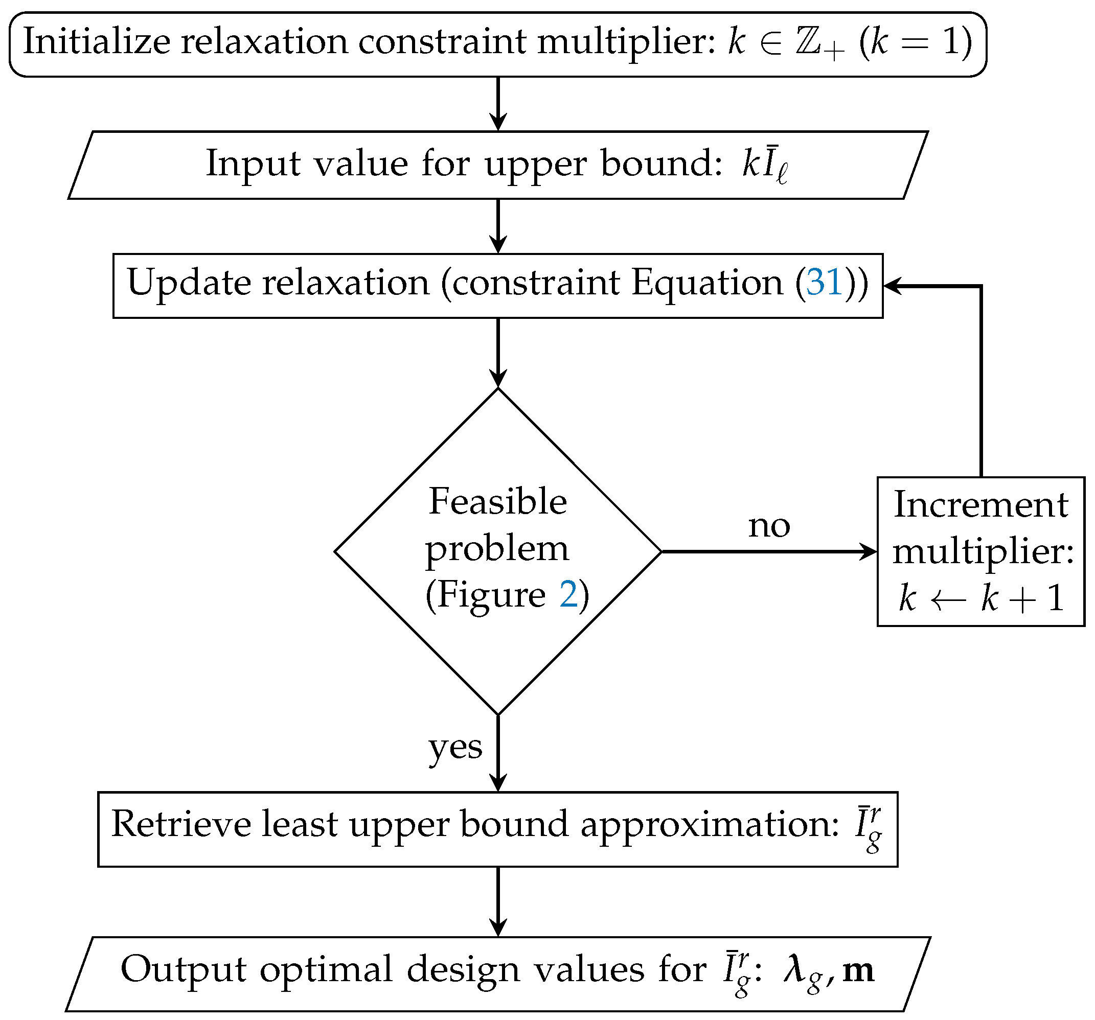
where k is iteratively increased to find the minimum integer value that relaxes Equation (30) as little as possible and gives a feasible solution simultaneously. This procedure is graphically illustrated in Figure 2, where the red and green areas correspond to non-feasible and feasible regions, respectively. The bound  k I ¯  is iteratively updated with increasing k until the problem lies inside the feasible region. This concept, of iteratively solving relaxed versions of the formulated optimization problem, is implemented through the flowchart presented in Figure 3. First, the relaxation constraint is initialized by setting the multiplier k of Equation (31) equal to 1. Then, the upper bound  k I ¯  is calculated updating constraint Equation (31). The iterative procedure for checking problem feasibility (see Figure 2) is initiated and the multiplier k is correspondingly incremented until feasibility is first achieved. From the solution of this feasible problem, we can then get the approximation of the least upper bound current rating  I ¯ g r  and the corresponding optimal solution values for the variables  λ g , m , which are also the algorithm’s output.

3. Results of Optimal and Concurrent DG Capacity Allocation and Droop Design

To investigate the effectiveness of the proposed methodology, a reference case study of an autonomous dc MG was considered. For this case, the results from the optimization problem formulation related to the simultaneous DG capacity allocation and droop control design, as well as the robustness properties with respect to DG availability, are demonstrated and validated by higher-fidelity time-domain simulations.

3.1. DC Microgrid Case Study

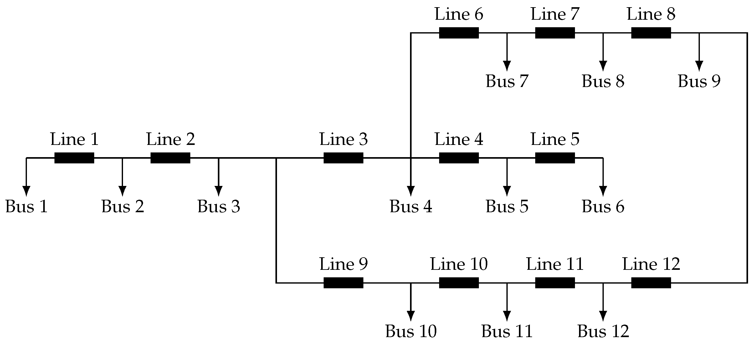
A generic, but realistic, dc MG consisting of various load types was selected as the case study. The grid topology is depicted in Figure 4 and the corresponding parameters are reported in Table 2. As can be seen from Table 2, different ZIP loads are attributed to the various buses of the MG, consisting of different proportions of constant impedance, constant current, and constant power characteristics, to capture different types of loads that could be found in such isolated systems.

3.2. Problem Solution Approach

The proposed problem formulation, described in detail in Section 2.1, can be efficiently solved using commercially available numerical optimization solvers for MILP problems. More specifically, the Gurobi 9.1.0 solver was employed in a 28 physical core multi-node cluster with Intel(R) Xeon(R) CPU E5-2690 v4 @ 2.60 Hz, 25 GB RAM. The robustness properties of the algorithm, with respect to the DGs availability, were investigated by solving different instances of the problem, ranging from full availability (a DG can be placed to each node) to half availability (only half of the grid buses are eligible for placing a DG).

3.2.1. DG Availability and Related Grid Patterns

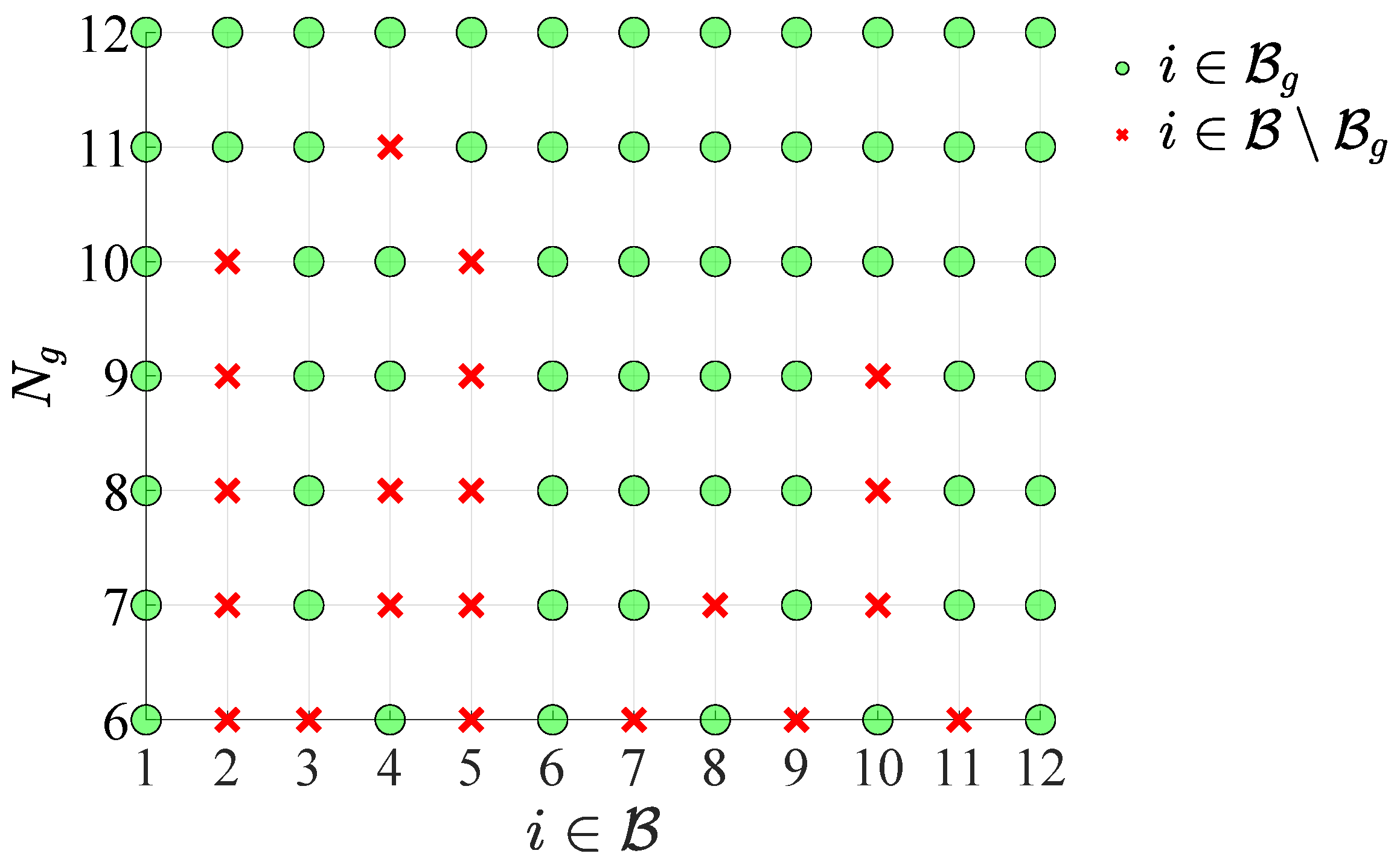
The proposed optimization framework can deal with variable DG availability and inform the decision-maker for various alternative grid design possibilities. To quantify the effect of DG availability on the problem solution, different cases were considered ( λ g , i  for  N g { 6 , , 12 } ); the associated optimal DG allocation solutions are graphically illustrated in Figure 5. In this figure, following similar notation as in Figure 1, green circles represent buses found eligible for DG placement (i.e.,  λ g , i = 1 ) and red crosses indicate the buses that are left without DGs (i.e.,  λ g , i = 0 ). Different levels of DG availability are plotted in different rows of the grid, marked with different values of  N g . From this perspective, the analyses performed revealed different patterns associated with the grid topology and the number of available generators, while also specifying the distribution of DGs in the MG for each case.
From Figure 5, we can directly observe that there exist specific dominant patterns of the optimal solution, persisting throughout the various designs. Specifically, for most of the designs ( N g 10 ), buses  i = 2  and  i = 5  are preferably left without a DG, whereas buses  i = 1 , 6 , 12  are found eligible for DG placement in all cases. Furthermore, by observing the grid layout from Figure 4, it is easy to notice that those buses are associated with the largest electrical distances in the network and they are spread across the whole grid area. In this way important locations for the grid are revealed, meaning that DGs placed in such locations can effectively support their neighbors’ nodes. Another interesting characteristic from the results of Figure 5 is related to trend reversals, as can be seen for bus  i = 4 . It is remarkable that, for  N g = 11  (which is the first case with reduced DG availability), this is the single bus selected to be left without a DG, but, with slightly decreased DG availability ( N g = 10 ), this is found eligible for placing a DG. This highlights the importance of finding case-specific optimal solutions for the problem, instead of deducing simplistic rules from other cases. For the remaining cases where  N g 10 , we observe that the removal patterns do not change significantly, whereas nodes that are left without DG tend to remain the same as the ones from the previous solution for decreasing  N g . Finally, we can observe that, for the extreme case of half availability ( N g = 6 ), the generators are almost perfectly spread over the network.

3.2.2. Optimal Droop Control Design

The proposed optimization formulation does not only recover the best grid locations for DGs ( λ g ) depending on their availability, but, at the same time, it finds proper and case-specific droop settings  m  combinations to achieve optimal current sharing among the DGs, as presented in the results below. The current-sharing quality is expressed through the ratio of the injected current from a DG to its rating  I g , i / I g , i r , and the closer these ratios are to each other, the better the current-sharing results. Here, it is worth mentioning that solving the problem defined in Section 2.1 means that a feasible power flow solution to the dc MG is found simultaneously. Thus, at the optimal solution, the resulting bus voltages  V  and corresponding current injections  I g  should verify the droop equation (Equation (2)) as much as possible. The droop coefficient can be recovered from the optimal solution as
m i = Δ V m a x I g r
The approximation of the non-linear terms, as explained in Section 2.1.4, inevitably leads to some numerical errors, reflected in the calculated nodal voltages and the voltage implied by the corresponding droop-governed current injection. To quantify this impact and assess the quality of the optimization result, the relative error term:
ϵ i v = V i V m a x m i I g , i V i .
is monitored and reported along with the optimization solution. Similarly, the relative error term  ϵ i v i  emerging from the approximation of the multivariate non-linearity  V i I g , i r  is calculated from the resulting nodal voltages and DG current ratings.
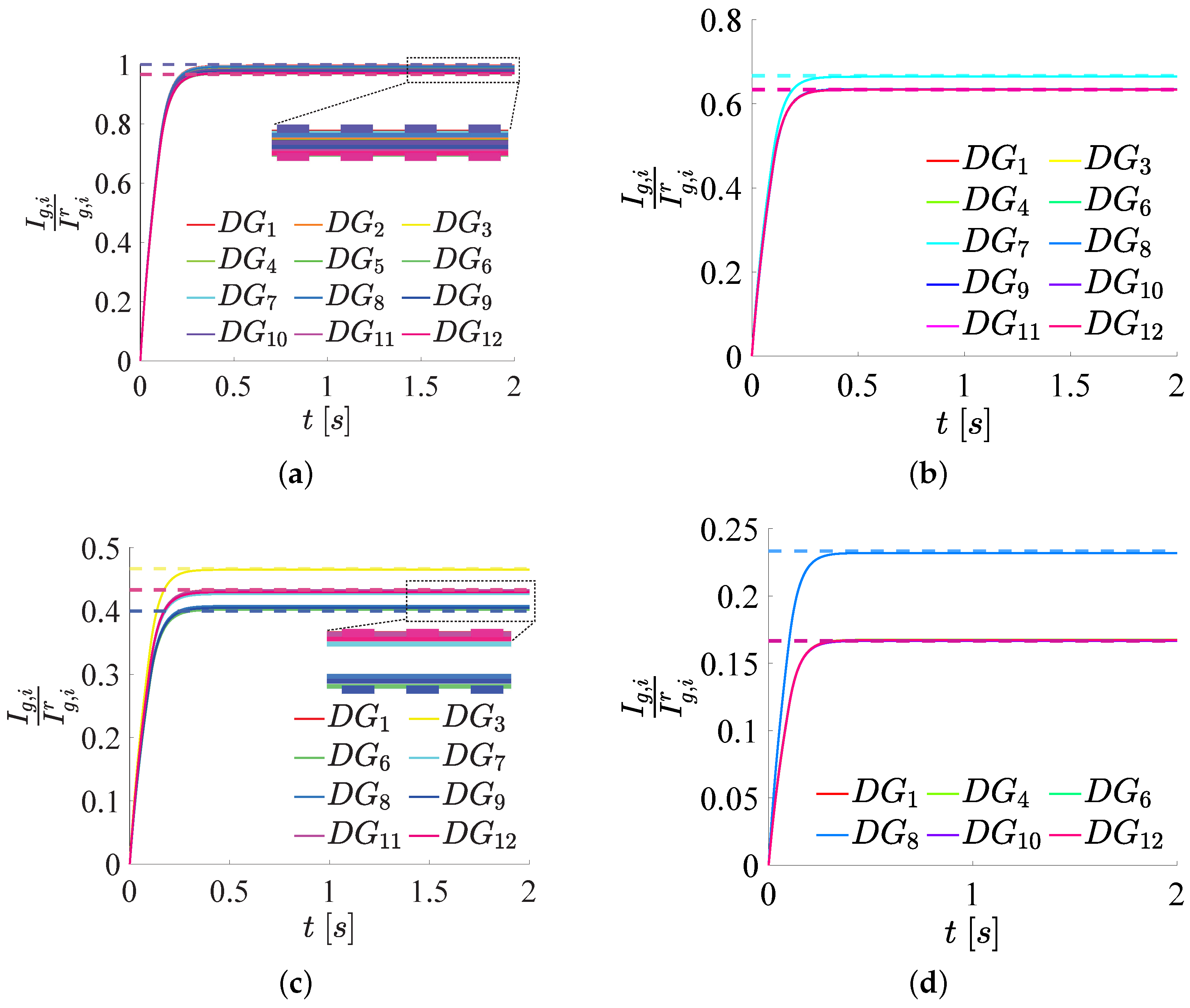
The above-defined metrics are presented, as an example, for two extreme cases, in Table 3 for full availability ( N g = 12 ) and in Table 4 for the least availability ( N g = 6 ) of DGs. Then, it is directly evident that, not only are errors very small for all cases, meaning that the approximations are of very high quality, but also that the calculated droop coefficients and current ratings verify the power flow solutions quite accurately. In addition, the high current-sharing quality achieved by the proposed method is also depicted by the calculated current ratios  I g , i / I g , i r  for the DGs. In particular, for the case of  N g = 12 , we notice that DGs are clustered in two groups with similar (almost the same) ratios, one at  I g , i I g , i r = 1  and another at  I g , i I g , i r = 0.967 . Their ratios values are very close to unity, further indicating that the DGs are almost perfectly used, given their available capacity, and that the total system capacity is not over-designed. Similar high-quality current sharing can be observed for the extreme case of half availability ( N g = 6 ), where a single value for the utilization ratio prevails. However, we notice that, in this case, this value is much less than unity, highlighting the importance of imposing the constraints given in Equations (28)–(31) in order to achieve high-quality solutions. In other words, decreasing the number of available DGs requires a significant over-sizing of the DGs that will be installed to achieve simultaneously feasible solutions and optimal current sharing.

3.3. Verification of the Optimal Design with Time Domain Simulations

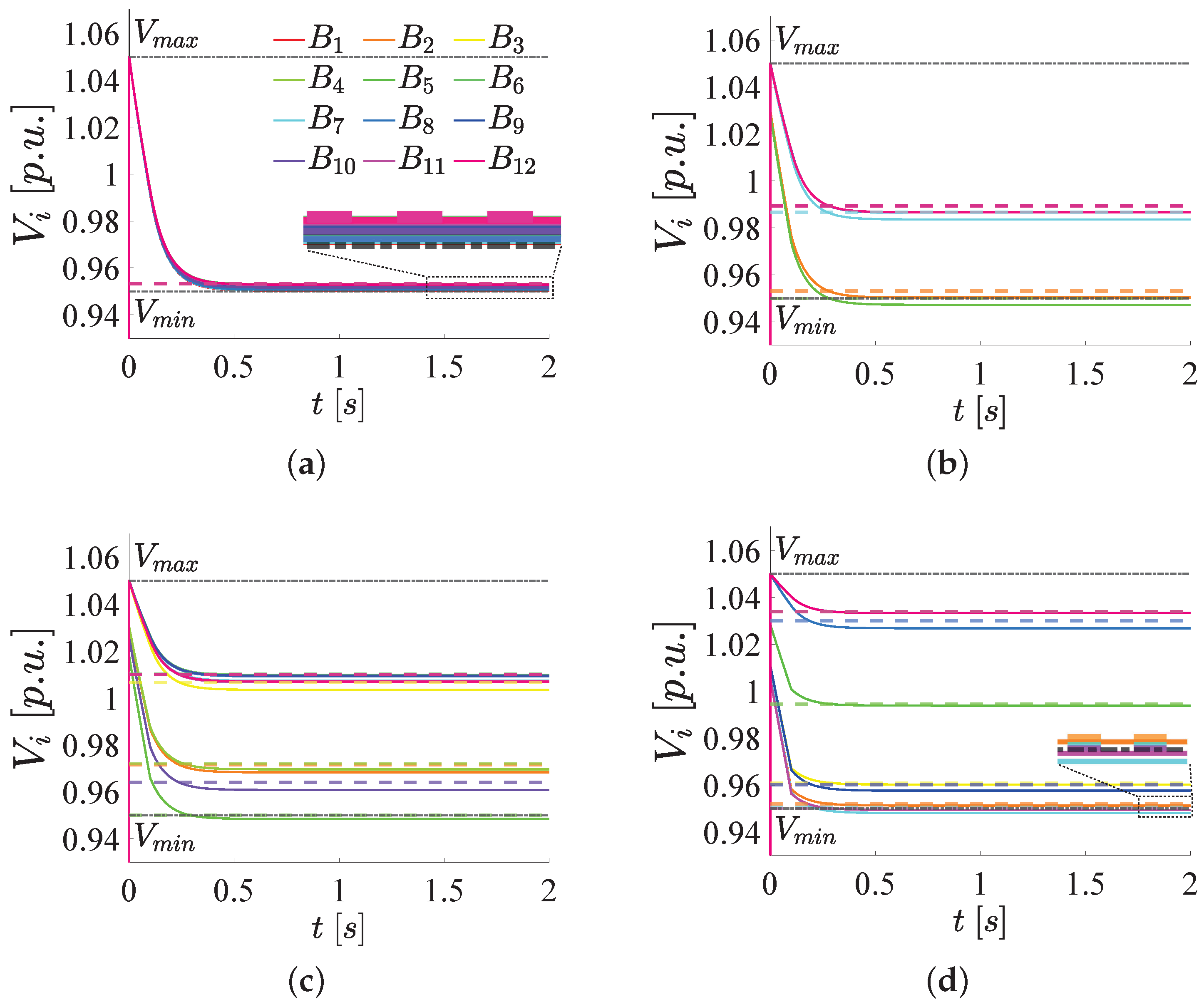
As mentioned before, the proposed optimization framework ensures that the optimal design (DG capacity allocation) for a given DG availability, will be associated with a feasible operating point of the dc MG. This is demonstrated through time domain simulations of a high-fidelity Simulink/Simscape model of the dc MG in Figure 4. This validation is illustrated in Figure 6 and Figure 7, where the steady state of the current injections and bus voltages converge to the corresponding operating point values, as predicted by the optimization result. A similar graphical notation is followed for both aforementioned figures, where dashed lines correspond to the operating point values and solid lines to the corresponding simulated variables. Different colors correspond to different DGs in Figure 6 and different buses in Figure 7, respectively.
In particular, from Figure 6, we observe the current-sharing capability of the optimal design for various levels of DG availability ( N g ). It is directly evident that the dynamic responses of all DGs converge to the calculated values with very high accuracy, meaning that the target current-sharing quality, associated with the optimal solution, can indeed be reproduced in the simulation framework. In other words, the droop laws of the DGs are designed such that the feasibility of the steady-state optimal current-sharing solution can be recovered in the dynamic environment. Then, we can also observe that, by reducing the DG availability, the utilization ratios tend to decrease, meaning that fewer DGs should be rated higher to compensate for the nodes without power injection. This fact is in agreement with the numerical results presented in Section 3.2.2. Again, we can see the grouping tendency, where different groups are formed depending on the DG availability. However, all DGs in the same group share the same utilization ratio, demonstrating the current-sharing capability.
Eventually, similar results can be deduced for the voltages of the dc MG buses, which are illustrated in Figure 7. Again, it is easily noticeable that, for all cases, the simulated dynamic responses converge to the steady-state values as calculated from the optimal solution with good accuracy, though not perfectly. There are some cases where a small deviation can be observed for some buses, where the optimal steady state values tend to slightly overestimate the simulated responses. However, this depends on the case study and is not consistent for the various levels of DG availability. These small deviations are attributed to the inevitable approximation errors of the non-linear terms (Section 2.1.4), but, nevertheless, they do not affect the qualitative characteristics of the steady-state solutions. In general, there is good agreement, and, most importantly, the nodal voltages are regulated in the allowable voltage range, ensuring both optimal and safe grid operation. It can also be observed that reducing the DGs’ availability is associated with more dispersed bus voltages. This is easy to see by comparing the two extreme cases of full and half availability ( N g = 12  and  N g = 6  in Figure 7a and Figure 7b respectively), where, for the former, all bus voltages are grouped close to the lower voltage limit, while, for the latter, different voltage levels are achieved for different buses spanning the whole available range. More specifically, when  N g 10 , all the buses have voltages lower than the nominal, while, for  N g < 10 , there exist buses with over-voltage, effectively exploiting the allowable voltage range. Finally, reducing the DG availability tends to give a higher maximum nodal voltage value, reflecting the need to increase the voltage locally at some nodes to support others.

4. Conclusions

The optimal coordination of multiple distributed generators in dc microgrids, ensuring their safe operation, is a challenging problem. This is because of the natural coupling between the control design problem (decentralized) and the siting decisions that define the grid topology. These interact through the grid dynamics and, therefore, should be considered simultaneously to achieve optimal coordination, expressed as current-sharing capabilities. In this paper, such a framework was proposed, enabling the proper selection of DG locations, while ensuring a safe microgrid operation under generic ZIP loads. A numerically efficient optimization algorithm was proposed for this task, incorporating non-linear characteristics associated with constant power loads and the power flows in the grid, as a function of the local controls. Such an algorithm can be used to support decision-makers in designing future dc MG enabling the solution of the capacity allocation and control design problems simultaneously, a task that has not yet been satisfactorily tackled by existing methods.
An iterative procedure was devised to guarantee the feasibility of the related optimization problem, while the effectiveness of the method was validated with time-domain simulations. The results revealed inherent patterns of the microgrid related to preferred bus locations for generator placement, leading to different possible grid designs with optimal current sharing among the generators, depending on their availability. Various clusters of buses and generators were identified with similar voltage levels and utilization ratios, respectively. The proposed framework is also suitable for stochastic representation of the loading conditions since such uncertainties could be easily integrated via a scenario formulation, leading to corresponding stochastic optimization problems, which could be considered a possible future research direction.

Author Contributions

Conceptualization, S.C. and B.A.; methodology, S.C.; software, S.C.; validation, S.C. and B.A.; formal analysis, S.C. and B.A.; investigation, S.C. and B.A.; resources, S.C. and B.A.; data curation, S.C.; writing—original draft preparation, S.C., B.A. and E.T.; writing—review and editing, S.C., B.A. and E.T.; visualization, S.C. and B.A.; supervision, E.T.; project administration, E.T. All authors have read and agreed to the published version of the manuscript.

Funding

This project/research was funded by VISTA—a basic research program in collaboration between The Norwegian Academy of Science and Letters, and Equinor, by the Onassis Foundation Scholarship ID: F ZP 056-1/2019-2020, and by the Department of Electric Energy, NTNU under Grant 988775100. This work was supported, in part, by the CINELDI—Centre for Intelligent Electricity Distribution, an 8-year Research Centre through the FME-Scheme (Centre for Environment-Friendly Energy Research) under Grant 257626/E20.

Conflicts of Interest

The authors declare no conflict of interest.

Abbreviations

  • The following abbreviations are used in this manuscript:
DGDistributed generator
MGMicrogrid
RESRenewable energy source
ESSEnergy storage system
PCCPoint of common coupling
SOSSpecial ordered set
LPLinear programming
IPInteger programming
MILPMixed-integer linear programming
MISOCPMixed-integer second-order optimization
MICVXOMixed-integer convex optimization
MetHMeta-heuristic
TLBOTeaching-learning-based optimization

Appendix A

Nodal voltages breakpoints
V ^ i = V ^ i , 1 , , V ^ i , N T , i B
Inverse nodal voltages breakpoints
L ^ i = Λ ^ i , 1 , , Λ ^ i , N T = V ^ i , 1 1 , , V ^ i , N 1 T , i B
DG current-rating breakpoints
I ^ g , i r = I ^ g , i , 1 r , , I ^ g , i , M r T , i B
DG current-rating times voltage breakpoints
P ^ g , i r = P ^ g , i , 1 , 1 r P ^ g , i , 1 , M r P ^ g , i , N , 1 r P ^ g , i , N , M r = V ^ i I ^ g , i r T , i B

References

  1. Chapaloglou, S.; Alves, E.; Trovato, V.; Tedeschi, E. Optimal Energy Management in Autonomous Power Systems with Probabilistic Security Constraints and Adaptive Frequency Control. IEEE Trans. Power Syst. 2023, 1–12. [Google Scholar] [CrossRef]
  2. Ton, D.T.; Smith, M.A. The U.S. Department of Energy’s Microgrid Initiative. Electr. J. 2012, 25, 84–94. [Google Scholar] [CrossRef]
  3. Hatziargyriou, N.; Asano, H.; Iravani, R.; Marnay, C. Microgrids. IEEE Power Energy Mag. 2007, 5, 78–94. [Google Scholar] [CrossRef]
  4. Meng, L.; Shafiee, Q.; Trecate, G.F.; Karimi, H.; Fulwani, D.; Lu, X.; Guerrero, J.M. Review on Control of DC Microgrids and Multiple Microgrid Clusters. IEEE J. Emerg. Sel. Top. Power Electron. 2017, 5, 928–948. [Google Scholar]
  5. Al-Ismail, F.S. DC Microgrid Planning, Operation, and Control: A Comprehensive Review. IEEE Access 2021, 9, 36154–36172. [Google Scholar] [CrossRef]
  6. Lotfi, H.; Khodaei, A. AC versus DC Microgrid Planning. IEEE Trans. Smart Grid 2017, 8, 296–304. [Google Scholar] [CrossRef]
  7. Albea-Sanchez, C. Hybrid dynamical control based on consensus algorithm for current sharing in DC-bus microgrids. Nonlinear Anal. Hybrid Syst. 2021, 39, 100972. [Google Scholar] [CrossRef]
  8. Han, Y.; Ning, X.; Yang, P.; Xu, L. Review of Power Sharing, Voltage Restoration and Stabilization Techniques in Hierarchical Controlled DC Microgrids. IEEE Access 2019, 7, 149202–149223. [Google Scholar] [CrossRef]
  9. Abdolmaleki, B.; Shafiee, Q.; Sadabadi, M.S.; Dragicevic, T. Economical Secondary Control of DC Microgrids. In Proceedings of the 2020 IEEE 11th International Symposium on Power Electronics for Distributed Generation Systems (PEDG), Dubrovnik, Croatia, 28 September–1 October 2020; pp. 304–308. [Google Scholar] [CrossRef]
  10. Abdolmaleki, B.; Bergna-Diaz, G. Distributed Control and Optimization of DC Microgrids: A Port-Hamiltonian Approach. IEEE Access 2022, 10, 64222–64233. [Google Scholar] [CrossRef]
  11. Abdolmaleki, B.; Bergna-Diaz, G. A Nonlinear Control Framework for Optimal Load-Sharing and Voltage Containment in DC Networks. IEEE Trans. Power Syst. 2023, 38, 976–979. [Google Scholar] [CrossRef]
  12. Georgilakis, P.S.; Hatziargyriou, N.D. Optimal Distributed Generation Placement in Power Distribution Networks: Models, Methods, and Future Research. IEEE Trans. Power Syst. 2013, 28, 3420–3428. [Google Scholar] [CrossRef]
  13. Gupta, Y.; Doolla, S.; Chatterjee, K.; Pal, B.C. Optimal DG Allocation and Volt–Var Dispatch for a Droop-Based Microgrid. IEEE Trans. Smart Grid 2021, 12, 169–181. [Google Scholar] [CrossRef]
  14. Chapaloglou, S.; Abdolmaleki, B.; Tedeschi, E. Optimal Sizing and Placement of Droop-based Converters in DC Microgrids with ZIP Loads. In Proceedings of the 2022 Second International Conference on Sustainable Mobility Applications, Renewables and Technology (SMART), Virtual, 23–25 November 2022; pp. 1–8. [Google Scholar] [CrossRef]
  15. Iqbal, S.; Khan, H.A.; Nasir, M. Sizing of Low-Power DC Microgrids with Intermittent AC Grids in Developing Regions. In Proceedings of the 2019 IEEE Power Energy Society General Meeting (PESGM), Atlanta, GA, USA, 4–8 August 2019; pp. 1–5. [Google Scholar]
  16. Nasir, M.; Iqbal, S.; Khan, H.A. Optimal Planning and Design of Low-Voltage Low-Power Solar DC Microgrids. IEEE Trans. Power Syst. 2018, 33, 2919–2928. [Google Scholar] [CrossRef]
  17. Phurailatpam, C.; Rajpurohit, B.S.; Wang, L. Planning and optimization of autonomous DC microgrids for rural and urban applications in India. Renew. Sustain. Energy Rev. 2018, 82, 194–204. [Google Scholar] [CrossRef]
  18. Che, L.; Zhang, X.; Shahidehpour, M.; Alabdulwahab, A.; Al-Turki, Y. Optimal Planning of Loop-Based Microgrid Topology. IEEE Trans. Smart Grid 2017, 8, 1771–1781. [Google Scholar] [CrossRef]
  19. Wang, P.; Zhang, L.; Xu, D. Optimal Sizing of Distributed Generations in DC Microgrids with Lifespan Estimated Model of Batteries. In Proceedings of the 2018 21st International Conference on Electrical Machines and Systems (ICEMS), Jeju, Republic of Korea, 7–10 October 2018; pp. 2045–2049. [Google Scholar]
  20. Molina-Martin, F.; Montoya, O.D.; Grisales-Noreña, L.F.; Hernández, J.C. A Mixed-Integer Conic Formulation for Optimal Placement and Dimensioning of DGs in DC Distribution Networks. Electronics 2021, 10, 176. [Google Scholar] [CrossRef]
  21. Grisales-Noreña, L.F.; Montoya, O.D.; Ramos-Paja, C.A.; Hernandez-Escobedo, Q.; Perea-Moreno, A.J. Optimal Location and Sizing of Distributed Generators in DC Networks Using a Hybrid Method Based on Parallel PBIL and PSO. Electronics 2020, 9, 1808. [Google Scholar] [CrossRef]
  22. Zhou, J.; Xu, Z. Optimal sizing design and integrated cost-benefit assessment of stand-alone microgrid system with different energy storage employing chameleon swarm algorithm: A rural case in Northeast China. Renew. Energy 2023, 202, 1110–1137. [Google Scholar] [CrossRef]
  23. Wu, X.; Wang, Z.; Ding, T.; Li, Z. Hybrid AC/DC Microgrid Planning with Optimal Placement of DC Feeders. Energies 2019, 12, 1751. [Google Scholar] [CrossRef] [Green Version]
  24. Krishnamurthy, N.K.; Sabhahit, J.N.; Jadoun, V.K.; Gaonkar, D.N.; Shrivastava, A.; Rao, V.S.; Kudva, G. Optimal Placement and Sizing of Electric Vehicle Charging Infrastructure in a Grid-Tied DC Microgrid Using Modified TLBO Method. Energies 2023, 16, 1781. [Google Scholar] [CrossRef]
  25. Khon, K.; Chhlonh, C.; Vai, V.; Alvarez-Herault, M.C.; Raison, B.; Bun, L. Comprehensive Low Voltage Microgrid Planning Methodology for Rural Electrification. Sustainability 2023, 15, 2841. [Google Scholar] [CrossRef]
  26. Alanazi, A.; Lotfi, H.; Khodaei, A. Optimal Energy Storage Sizing and Siting in Hybrid AC/DC Microgrids. In Proceedings of the 2018 North American Power Symposium (NAPS), Fargo, ND, USA, 9–11 September 2018; pp. 1–6. [Google Scholar] [CrossRef]
  27. Jabr, R.A. Mixed-Integer Convex Optimization for DC Microgrid Droop Control. IEEE Trans. Power Syst. 2021, 36, 5901–5908. [Google Scholar] [CrossRef]
  28. Shi, L.; Liu, Q.; Shao, J.; Cheng, Y.; Zheng, W.X. A Cooperation-Competition Evolutionary Dynamic Model Over Signed Networks. IEEE Trans. Autom. Control 2023, 1–8. [Google Scholar] [CrossRef]
  29. Shi, L.; Li, W.; Shi, M.; Shi, K.; Cheng, Y. Opinion Polarization Over Signed Social Networks with Quasi Structural Balance. IEEE Trans. Autom. Control 2023, 1–8. [Google Scholar] [CrossRef]
  30. IEEE Std 1547-2018 (Revision of IEEE Std 1547-2003); IEEE Standard for Interconnection and Interoperability of Distributed Energy Resources with Associated Electric Power Systems Interfaces. IEEE: Piscataway Township, NJ, USA, 2018; pp. 1–138. [CrossRef]
  31. D’Ambrosio, C.; Lodi, A.; Martello, S. Piecewise linear approximation of functions of two variables in MILP models. Oper. Res. Lett. 2010, 38, 39–46. [Google Scholar] [CrossRef]
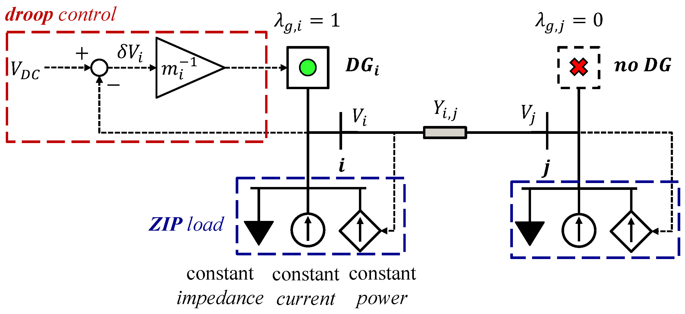
Figure 1. Graphical representation of the considered dc MG structure. A line segment between two buses is illustrated, where, at each bus, a ZIP load is assigned. Only bus i is selected for DG placement and the corresponding local droop control is shown.
Energies 16 04583 g001
Figure 2. Graphical illustration of the iterative procedure for feasibility recovery of the optimization problem. The red region represents a range of  I ¯ g r  values leading to a non-feasible problem, while the green is the range leading to a feasible problem. The upper bound  k I ¯  is iteratively updated until it first enters the green region.
Energies 16 04583 g002
Figure 3. Flowchart for the implementation of the procedure illustrated in Figure 2. The algorithm iteratively updates the aggregated generation capacity constraint, relaxing the optimization problem, until a feasible solution is achieved, which is also the output quantity of interest.
Energies 16 04583 g003
Figure 4. Topology of the dc microgrid considered as a test case study.
Energies 16 04583 g004
Figure 5. Optimal allocation of the DGs in the dc microgrid, for decreasing DG availability (green circles represent grid nodes with a DG, and red crosses represent the buses left without a DG).
Energies 16 04583 g005
Figure 6. Current sharing capability in the dc microgrid, expressed through the ratios of injected currents over current ratings for each DG and for various levels of DG availability. (a N g = 12 . (b N g = 10 . (c N g = 8 . (d N g = 6 .
Energies 16 04583 g006
Figure 7. Bus voltages in the dc microgrid for various levels of DG availability, corresponding to the current-sharing results of Figure 6 (same color convention for all subfigures). (a N g = 12 . (b N g = 10 . (c N g = 8 . (d N g = 6 .
Energies 16 04583 g007
Table 1. Summary of related work (✓: includes, ×: does not include). The methods include linear programming (LP), integer linear programming (IP), meta-heuristic (MetH) techniques, mixed-integer second-order conic optimization (MISOCP), and mixed-integer convex optimization (MICVXO). HOMER stands for the Hybrid Optimization of Multiple Energy Resources software.
Ref No.SizingPlacementDroop DesignMethod
[15]××LP
[16]××LP
[17]××HOMER-based
[18]××IP
[19]××MetH
[22]××MetH
[23]××MILP
[24]×MetH
[25]×MILP + Clustering
[26]×MILP
[20]×MISOCP
[21]×MetH
[27]××MICVXO
This WorkMILP
Table 2. Line parameters (resistance) and load specifications (conductance, constant current, and constant power values) for the dc microgrid of Figure 4.
Line /   i B   R L , i [ Ω ]   G i [ S ]   I i c [ A ]   P i c [ kW ]
10.2500.3002.0039.0963
20.1500.2003.0026.0642
30.2000.2505.0032.5802
40.2500.1001.0013.0321
50.3000.1501.5019.5481
60.3500.3002.5039.0963
70.1500.4003.0052.1284
80.2500.3001.5039.0963
90.4000.2005.0026.0642
100.2500.1502.0019.5481
110.3500.3002.0039.0963
120.6500.2003.0026.0642
Table 3. Current injections and achieved current-sharing quality among DGs, along with approximation errors related to optimization modeling, for  N g = 12 .
i B g I g , i [ A ] I g , i r [ A ] I g , i I g , i r [ ] m i V A ϵ i v [ % ] ϵ i vi [ % ]
1218.60218.601.0000.16800.3497−0.3509
2147.40147.401.0000.16800.34970.2578
3185.50191.900.9670.1980−4  × 10 14   6 × 10 14
473.2073.201.0000.50180.3497−0.3509
5109.80113.590.9670.3345   4 × 10 14   3 × 10 14
6219.10226.660.9670.1677   4 × 10 14   5 × 10 14
7291.80291.801.0000.12590.3497−0.3509
8218.10218.101.0000.16840.3497−0.3509
9149.40154.550.9670.2459   4 × 10 14   3 × 10 14
10110.30110.301.0000.33300.3497−0.3509
11218.60218.140.9670.1680   4 × 10 14   5 × 10 14
12147.40152.480.9670.2492   1 × 10 14   5 × 10 14
Table 4. Current injections and achieved current-sharing quality among DGs, along with approximation errors related to optimization modeling, for  N g = 6 .
i B g I g , i [ A ] I g , i r [ kA ] I g , i I g , i r [ ] m i V A ϵ i v [ % ] ϵ i vi [ % ]
1344.062.0640.16670.01780.0541−0.0541
4362.732.1760.16670.01690.0541−0.0541
6269.841.6190.16670.02270.0541−0.0541
8526.382.2560.23330.01440.3236−0.3247
10307.611.8460.16670.01990.0541−0.0541
12282.151.6930.16670.02170.0541−0.0541
Disclaimer/Publisher’s Note: The statements, opinions and data contained in all publications are solely those of the individual author(s) and contributor(s) and not of MDPI and/or the editor(s). MDPI and/or the editor(s) disclaim responsibility for any injury to people or property resulting from any ideas, methods, instructions or products referred to in the content.