Article

Analytical Calculation of Air Gap Magnetic Field of SPMSM with Eccentrically Cut Poles Based on Magnetic Pole Division

1
Institute of Electrical Engineering, Chinese Academy of Sciences, Beijing 100101, China
2
University of Chinese Academy of Sciences, Beijing 101408, China
3
Dongfang Electric Machinery Co., Ltd., Chengdu 611731, China
*
Author to whom correspondence should be addressed.
Energies 2023, 16(11), 4450; https://doi.org/10.3390/en16114450
Submission received: 11 April 2023 / Revised: 18 May 2023 / Accepted: 29 May 2023 / Published: 31 May 2023
(This article belongs to the Section F: Electrical Engineering)

Abstract

:
In the design process of surface-mounted permanent magnet motor (SPMSM) for industrial robots and computer numerical control (CNC) machine tools, to pursue the sinusoidal nature of the back electromotive force, the magnetic poles in the form of eccentric pole cutting structure are often used. To analyze the no-load air gap magnetic field of the SPMSM with eccentrically cut poles simply and accurately, a subdomain model magnetic field analytical calculation method based on equal-area integral block processing of permanent magnets is proposed. The problem that the traditional subdomain analysis model cannot be directly applied to the SPMSM with eccentrically cut poles of unequal thickness is solved. The proposed method considers the influence of stator slotting and the actual permeability of permanent magnets, and directly obtains the fundamental wave and harmonic components of the no-load air gap flux density by solving the subdomain model. The finite element method (FEM) is used to directly calculate the air gap magnetic field for verification. The results of the analytical method and the no-load air gap magnetic density calculated by the FEM are consistent, which verifies the accuracy of the proposed analytical method and can quickly guide the design of the SPMSM with eccentrically cut poles.

1. Introduction

Due to its simple structure, high efficiency, high power density, and other advantages, SPMSM has shown broad application prospects in many fields. Therefore, improving the sine degree of the air gap magnetic field waveform of the SPMSM and reducing the harmonic magnetic density content of the air gap magnetic field are important measures to improve the operating performance of the SPMSM [1,2,3]. To reduce the harmonic content in the air gap magnetic density, there are many ways of cutting poles during the magnetic pole design process of the SPMSM. There are mainly sine pole cutting, arc-cosine pole cutting, eccentric pole cutting, and harmonic pole cutting. Considering the actual engineering requirements and processing technology, eccentric pole cutting is relatively easy to implement and can obtain a more ideal air gap magnetic field waveform [4]. The basis for realizing eccentric pole cutting and optimizing the magnetic pole shape is the accurate calculation of the no-load air gap magnetic field.
There are two main methods for analyzing and calculating the no-load air gap magnetic field: the FEM and the analytical method. The calculation results of the FEM have high accuracy and can accurately consider the influence of magnetic flux leakage, saturation, and complex cogging structure. References [5,6] proposed an improved FEM for SPMSM. The analytical method has the advantages of fast speed, a small amount of calculation, and a clear physical concept, which are beneficial to the initial scheme design and optimization of the motor. Analytical calculation methods mainly include the equivalent magnetic network method, subdomain model method, and harmonic modeling method [7,8,9,10]. Due to its structural characteristics that can be processed in different regions, the analytical method can be used to quickly analyze and calculate the no-load air gap magnetic field of the SPMSM.
The subdomain model method [11,12,13,14,15,16,17,18,19,20] is a high-precision analytical method of the electromagnetic field of a motor. Applying this method to calculate the SPMSM with eccentrically cut poles can obtain a high-precision analytical solution; however, when the subdomain model is adopted, the eccentric poles need to be treated equivalently. Reference [21] proposed a combination subdomain model of inner and outer arcs, established a unified description model of rotation, arc, and straight-line SPMSM, and provided the selection method for model parameters when the unified description model analyzed different motor structures. In [22], the rapidity of the subdomain model method was used to introduce the second-generation non-dominated sorting genetic algorithm (NSGA-Ⅱ) to optimize the design of the SPMSM. Reference [23] introduced the concept of a unit motor for the SPMSM using a non-magnetic slot wedge and segmented skew pole, established an accurate subdomain model, and verified the accuracy of the proposed method. Reference [24] used the subdomain model method to calculate the internal magnetic field of the hybrid vernier motor and used the analytical calculation results to study the influence of the slot width on the torque. Based on the Fourier series method, Zhu et al. established an accurate subdomain model of the SPMSM considering the slot effect and a semi-open slot model. Compared with the FEM results, this method has a high calculation accuracy [11,12]. For SPMSM with eccentrically cut poles, various analytical methods have been proposed in different literatures, such as the equivalent surface current method, the one-dimensional magnetic circuit analysis method, etc. Reference [3] deduced the air gap magnetic density analytic formula of a parallel magnetized motor with eccentrically cut poles in consideration of the actual magnetic permeability of the permanent magnet, calculated the harmonic distortion rate, and scanned and optimized the optimal eccentricity and polar arc coefficient. In [19], based on the principle of vector magnetic potential superposition, the permanent magnet is found to be equivalent to the current on each surface, the analytical model of the SPMSM considering slotting is established, and the air gap magnetic field under eccentric pole cutting is calculated. Reference [25] proposes a mixed magnetic field analysis method based on the subdomain model method for SPMSM with eccentrically cut poles. Considering the actual B-H curve of ferromagnetic materials, the correction coefficient is obtained through iterative calculations, and the no-load air gap magnetic field is corrected. In the literature [26], the magnetic poles of the spoke permanent magnet motor are equivalent to fan-shaped regions with different pole arc coefficients, and considering the influence of the armature reaction, an analytical calculation of the magnetic field is carried out by using the subdomain model method. In the literature [27], the SPMSM of the bread-shaped magnetic pole is equivalently divided into blocks, and the internal magnetic field of the motor is calculated by using the subdomain model method. Literature [28] proposes an equiangular block method for SPMSM with eccentrically cut poles. The magnetic poles of eccentric pole cutting are divided into equiangular blocks, and the magnetic fields are calculated separately and then superimposed.
In this paper, for the SPMSM with eccentrically cut poles, the subdomain model method in the analytical method is used to integrate the magnetic poles into equal-area blocks. An analytical calculation model of the air gap magnetic field of an eccentric pole-cut SPMSM based on magnetic pole segmentation is proposed, and the air gap magnetic field distribution of the SPMSM with eccentrically cut poles at no-load is calculated. Compared with the equal-angle blocking method, the proposed method ensures that the magnetic energy products of each pole block are equal, reduces the number of blocks, and improves the accuracy of the calculation. The accuracy of the proposed method is verified by comparing the calculation results of the analytical method and FEM.

2. Analytical Solution Process of Air Gap Magnetic Field

To establish the analytical solution model of the motor, the following assumptions are made [29,30]:
(1)
The magnetic permeability of the ferromagnetic material is set to infinity.
(2)
The magnetic permeability of the air gap between the magnetic poles is the same as that of the permanent magnet.
(3)
The stator slot type is a radial fan-shaped open slot with a regular shape.
(4)
Neglecting the end effect, the model is solved in the two-dimensional region.

2.1. The Model of the Eccentrically Cut Permanent Magnet and Its Equal-Area Integral Block

Figure 1a shows the structure of the eccentric pole-cutting permanent magnet and its schematic diagram after equal-area subdivision. The centerline of the rotor is the d -axis, and O 1 is the center of the inner arc of the magnetic pole, that is, the center of the stator and rotor of the motor. O 2 is the center of the outer arc; R 1 is the radius of the inner arc of the magnetic pole, that is, the radius of the rotor yoke; R 2 is the radius of the outer arc of the magnetic pole; R j is the radius of the j th magnetic block; θ 1 is the central angle of the inner arc of the magnetic pole; θ 2 is the central angle of the outer arc of the magnetic pole; and φ j is the central angle of the magnetic pole of block j th .
The magnetic pole is divided into several magnetic pole pieces of equal area; each magnetic pole piece has the same area, and their respective equivalent inner and outer arcs are concentric; each magnetic pole block is analyzed and calculated by the analytical method, and the results are linearly superimposed. Considering the symmetry of the magnetic pole structure, each half-pole is used as the block basis when dividing into blocks, and then in one 2 π electric period, that is, in a pair of poles, the rest of the half-poles copy the block method of the reference half-pole. This not only facilitates the expression of the Fourier series and its coefficient solution but also avoids the rotation problem of the magnetization vector and effectively improves the calculation efficiency. In addition, the calculation results obtained will have high accuracy regardless of the number of blocks.
In Figure 1a, the angle of the counterclockwise rotation along the d axis is set to be positive, and half of the magnetic pole corresponding to the electrical angle 0 to 90 area is used as the reference magnetic pole. The total number of blocks for half a magnetic pole is N p , and the serial numbers of the permanent magnets are arranged as 1 ,   2 ,   ,   N p  starting from the d axis along the direction of the increasing angle. Since the magnetic poles are unequal thick tiles and equal-area integral blocks, the central angle and radius of each magnetic pole block are different. According to the principle of area equivalence, it can be obtained as follows:
1 2 N p · [ 1 2 ( R 2 2 θ 2 R 1 2 θ 1 ) + R 1 R 2 sin ( 1 2 θ 2 1 2 θ 1 ) ] = 1 2 ( R j 2 φ j R 1 2 φ j )
The magnetic pole area is:
S m a g n e t i c   p o l e = 1 2 ( R 2 2 θ 2 R 1 2 θ 1 ) + R 1 R 2 sin ( 1 2 θ 2 1 2 θ 1 )
The equivalent radius and central angle of each pole block can be obtained as follows:
R j = S m a g n e t i c   p o l e ( 1 + N p ) j θ 1 + R 1 2
φ j = j θ 1 N p ( 1 + N p )
The central angle of the center point of the j th permanent magnet relative to the d axis is as follows:
φ j d = j 2 θ 1 2 N p ( 1 + N p )
In the analysis and calculation process of the electromagnetic field analysis method, it is not only necessary to perform calculations through geometric and triangular methods, but it also involves the Fourier decomposition of the entire period. Since the nature of the required angles is different, for the sake of unity, the angles below are generally mechanical angles, and if electrical angles are required, it is the product of the mechanical angle and the number of pairs of poles p .

2.2. General Solution of Each Subdomain

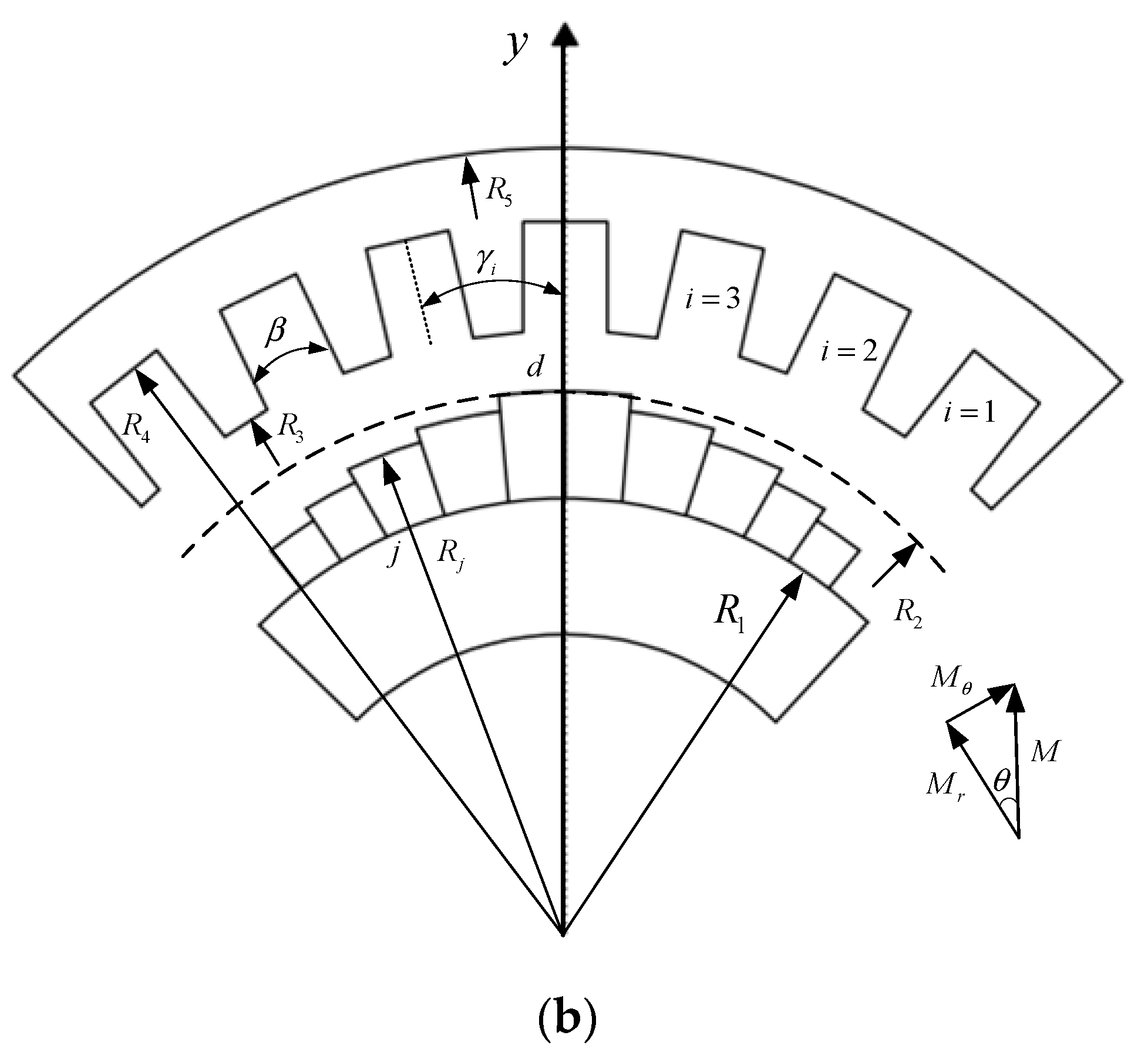
The premise of using the subdomain method is to divide the motor into subdomains. The cross-section of the SPMSM is shown in Figure 1b. The subdomains are divided into three as follows: the first subdomain is the slot; the second subdomain is the air gap; the third subdomain is the pole. R 3 is the radius at the top of the slot, R 4 is the radius at the bottom of the slot, and β is the central angle corresponding to the slot. γ i is the position angle of the center of the i th slot, and the stator has N s slots, so there is γ i = 2 π i / N s , and the starting position of the i th slot is defined as θ i = γ i β / 2 . Without the loss of generality, the polar coordinate y axis of the stator is set to coincide with the magnetic pole centerline d  axis.

2.2.1. Subdomain 1—Slot

For a constant magnetic field, the Laplace equation of the vector magnetic potential in the stator slot can be obtained from the Ampere loop law and Gauss law:
2 A 1 i ( r , θ ) r 2 + 1 r A 1 i ( r , θ ) r + 1 r 2 2 A 1 i ( r , θ ) θ 2 = 0
A 1 i ( r , θ ) represents the vector magnetic potential in the i th stator slot. To facilitate the expression of the general solution of each subdomain and the solution of the harmonic coefficients, the following two functions are defined [28]:
{ P x ( y , z ) = ( y z ) x + ( z y ) x E x ( y , z ) = ( y z ) x ( z y ) x
Therefore, according to the separation of variables method, the general solution form of the slot subdomain is obtained as follows:
A 1 i ( r , θ ) = A 1 i 0 + k = 1 A 1 i k P τ k ( r , R 4 ) P τ k ( R 3 , R 4 ) cos [ τ k ( θ θ i ) ]
where, τ k = k π / β , k are the harmonic orders in the stator slot, which are positive integers.

2.2.2. Subdomain 2—Air Gap

The air gap is a ring-shaped area, and in the air gap subdomain, there is neither current density distribution nor magnetization vector component, so its vector magnetic potential equation can be expressed as follows:
2 A 2 ( r , θ ) r 2 + 1 r A 2 ( r , θ ) r + 1 r 2 2 A 2 ( r , θ ) θ 2 = 0
Using the same method of variable separation, the form of the vector magnetic potential flux in the air gap can be obtained as follows:
A 2 ( r , θ ) = n = 1 [ R 2 n p P n p ( r , R 3 ) E n p ( R j , R 3 ) A 2 n R 3 n p P n p ( r , R 2 ) E n p ( R j , R 3 ) B 2 n ] cos ( n p θ ) + n = 1 [ R 2 n p P n p ( r , R 3 ) E n p ( R j , R 3 ) C 2 n R 3 n p P n p ( r , R 2 ) E n p ( R j , R 3 ) D 2 n ] sin ( n p θ )

2.2.3. Subdomain 3—Permanent Magnet

In this paper, radially magnetized poles are used, so the tangential component of the magnetization vector is 0. In the half-pole region of electrical angle 0 to π / 2 shown in Figure 1b, the radial component of the magnetization vector of the block magnetic pole of the j th block is as follows:
M r j ( p θ ) = B r μ 0   ,   p ( φ j d 1 2 φ j ) p θ p ( φ j d + 1 2 φ j )
where B r represents the remanence density of the permanent magnet.
The tangential component of the magnetization vector of the j th block is as follows:
M θ j ( p θ ) = 0
The radial and tangential components of the magnetization vector are expanded within the range of one pair of poles, that is, within 2 π periods of the electrical angle. The radial component of the magnetization vector is an even function expressed in the Fourier series as follows:
M r j ( p θ ) = n = 1 , 3 , 5 M r j n cos ( n p θ )
where:
M r j n = 4 p B r n μ 0 π { sin [ n ( φ j d + 1 2 φ j ) ] sin [ n ( φ j d 1 2 φ j ) ] }
The Laplace equation in the polar coordinate system in the permanent magnet is listed, and it is solved by the same separation of variables method, and its general solution expression is as follows:
A 3 ( r , θ ) = n = 1 [ P n p ( r , R 1 ) A 3 n P n p ( R j , R 1 ) ] cos ( n p θ ) + n = 1 [ P n p ( r , R 1 ) C 3 n P n p ( R j , R 1 ) K s n ] sin ( n p θ )
For the above formula,
K s n ( r ) = λ s n ( r ) P n p ( r , R 1 ) P n p ( R j , R 1 ) [ λ s n ( R j ) + ( R 4 n p ) · ( R 4 R j ) n p λ s n ( R 1 ) ] + ( R 4 n p ) · ( R 4 R j ) n p λ s n ( R 1 )
where:
λ s n ( r ) = μ 0 ( n p M r j n + M θ j n ) r ( n p ) 2 1 , n / p = 1 , 3 , 5

2.3. Harmonic Coefficient Solution

The radial and tangential components of the magnetic density of each subdomain can be obtained by the vector magnetic potential:
B r = 1 r A z θ , B θ = A z r
Therefore, the magnetic density in the slot is the following:
B 1 i r = 1 r A 1 i θ = τ k r · k = 1 A 1 i k · P τ k ( r , R 4 ) P τ k ( R 3 , R 4 ) · sin [ τ k ( θ + β 2 γ i ) ]
B 1 i θ = A 1 i r = τ k r · k = 1 A 1 i k · E τ k ( r , R 4 ) P τ k ( R 3 , R 4 ) · cos [ τ k ( θ + β 2 γ i ) ]
The magnetic density in the air gap is as follows:
B 2 r j = n = 1 [ R j r · P n p ( r , R 3 ) E n p ( R j , R 3 ) · A 2 n R 3 r · P n p ( r , R j ) E n p ( R j , R 3 ) · B 2 n ] · sin ( n p θ ) + n = 1 [ R j r · P n p ( r , R 3 ) E n p ( R j , R 3 ) · C 2 n R 3 r · P n p ( r , R j ) E n p ( R j , R 3 ) · D 2 n ] · cos ( n p θ )
B 2 θ j = n = 1 [ R j r · E n p ( r , R 3 ) E n p ( R j , R 3 ) · A 2 n R 3 r · E n p ( r , R j ) E n p ( R j , R 3 ) · B 2 n ] · cos ( n p θ )   n = 1 [ R j r · E n p ( r , R 3 ) E n p ( R j , R 3 ) · C 2 n R 3 r · E n p ( r , R j ) E n p ( R j , R 3 ) · D 2 n ] · sin ( n p θ )
The flux density in the permanent magnet is the following:
B 3 r j = n p r · n = 1 [ P n p ( r , R 1 ) P n p ( R j , R 1 ) · A 3 n ] · sin ( n p θ ) + n p r · n = 1 [ P n p ( r , R 1 ) P n p ( R j , R 1 ) · C 3 n K s n ( r ) ] · cos ( n p θ )
B 3 θ j = n p r · n = 1 [ · E n p ( r , R 1 ) P n p ( R j , R 1 ) · A 3 n ] · cos ( n p θ ) n p r · n = 1 [ E n p ( r , R 1 ) P n p ( R j , R 1 ) · C 3 n K s n ( r ) ] · sin ( n p θ )

2.3.1. The Interface between Air Gap and Permanent Magnet

Between the permanent magnet and the air gap, the normal flux density is continuous, that is, at r = R j :
B 2 r | r = R j = B 3 r | r = R j
The following can be obtained:
{ ( G 1 2 + 1 ) · A 2 n R 3 R j · 2 G 1 · B 2 n n p R j · ( G 1 2 1 ) · A 3 n = 0 ( G 1 2 + 1 ) · C 2 n R 3 R j · 2 G 1 · D 2 n n p R j · ( G 1 2 1 ) · C 3 n = n p R j · ( G 1 2 1 ) · K s n ( R j )
where: ( R j R 3 ) n p = G 1 .
Equation (26) can be written in the matrix form as follows:
{ K 11 A 2 N   +   K 12 B 2 N   +   K 13 A 3 N   =   Y 1 K 21 C 2 N   +   K 22 D 2 N   +   K 23 C 3 N   =   Y 2
where, the coefficients A 2 N , B 2 N , C 2 N , D 2 N , A 3 N and C 3 N are column vectors constructed in the same way, for example: A 3 n = [ A 3 ( 1 ) , A 3 ( 2 ) , , A 3 ( N ) ] T , and there is:
K 11 = K 21 = G 1 2 + I N
K 12 = K 22 = 2 R 3 R j · G 1
K 13 = K 23 = p R j · N · ( G 1 2 I N )
Y 1   =   0
Y 2   =   p R j · N · ( G 1 2 I N ) · K SN ( R j )
where:
G 1 = d i a g ( G 1 ( p ) , G 1 ( 2 p ) , , G 1 ( N p ) )
N   =   d i a g ( 1 , 2 , , N )
I N   =   d i a g ( 1 , 1 , , 1 ) N × N
where N = n max is the maximum harmonic order of the air gap and permanent magnet subdomains. The magnetization vector is a column vector, and the construction method is the same, which is as follows:
M rjn = [ M r j 1 , M r j 2 , M r j N ] T
M θ jn = [ M θ j 1 , M θ j 2 , M θ j N ] T
Between the permanent magnet and the air gap, the tangential magnetic field strength is equal, that is, at r = R j :
B 2 θ j | r = R j = B 3 θ j | r = R j M θ j · μ 0
where, for permanent magnets, μ r 1
H 2 θ = B 2 θ μ 0
H 3 θ = B 3 θ μ 0 M θ μ r
Through Formula (38), the following can be obtained:
{ ( G 2 2 + 1 ) A 2 n + n p R j ( G 2 2 1 ) A 3 n = 0 ( G 2 2 + 1 ) C 2 n + n p R j ( G 2 2 1 ) C 3 n = ( G 2 2 + 1 ) K s n ( R j ) + ( G 2 2 + 1 ) M θ j n · μ 0
where: ( R 1 R j ) n p = G 2 .
Equation (41) can be written in the matrix form as follows:
{ K 31 A 2 n   +   K 32 A 3 n   =   Y 3 K 41 C 2 n   +   K 42 C 3 n   =   Y 4
where:
K 31 = K 41 = G 2 2 + I N
K 32 = K 42 = p R j · N · ( G 2 2 I N )
Y 3   =   0
Y 4 = ( G 2 2 + I N ) · [ K sn ( R j ) M θ jn · μ 0 ]
G 2 = d i a g ( G 2 ( p ) , G 2 ( 2 p ) , , G 2 ( N p ) )

2.3.2. The Interface between Air Gap and Stator Slot

The tangential component of magnetic density along the stator yoke can be obtained using the vector magnetic potential distribution in the stator slot:
B 1 i θ | r = R 3 = k = 1 B 1 i θ k · cos [ τ k ( θ θ i ) ]
where: B 1 i θ k = τ k R 3 · G 3 2 1 G 3 2 + 1 .
Because the stator yoke material in this paper has infinite magnetic permeability, the magnetic close component of the yoke outside the stator slot is zero. Therefore, the magnetic close component of the stator yoke is expanded into the form of the Fourier series.
B s θ = n [ C s cos ( n p θ ) + D s sin ( n p θ ) ]
where:
C s = 1 π 0 2 π B s θ cos ( n p θ ) d θ = Σ i Σ k B 1 i θ k η i
D s = 1 π 0 2 π B s θ sin ( n p θ ) d θ = Σ i Σ k B 1 i θ k ξ i
where:
η i ( k , n ) = 1 π n p τ k 2 ( n p ) 2 [ cos ( k π ) sin ( n p · γ i + n p · β 2 ) sin ( n p · γ i n p · β 2 ) ]
ξ i ( k , n ) = 1 π n p τ k 2 ( n p ) 2 [ cos ( k π ) cos ( n p · γ i + n p · β 2 ) cos ( n p · γ i n p · β 2 ) ]
According to the vector magnetic potential distribution in the air gap, the tangential component of the magnetic density along the stator yoke can also be expressed as follows:
B s θ = B 2 θ j | r = R 3 = n p R 3 · n = 1 [ R 3 n p · B 2 n ] cos ( n p θ ) n p R 3 · n = 1 [ R 3 n p · D 2 n ] sin ( n p θ )
According to Formulas (52) and (57), we can obtain the following:
{ A 1 i k · τ k R 3 · ( G 3 2 1 ) · η i ( G 3 2 + 1 ) · B 2 n = 0 A 1 i k · τ k R 3 · ( G 3 2 1 ) · ξ i ( G 3 2 + 1 ) · D 2 n = 0
Simultaneously, Formulas (52), (57), and (58) can obtain the following equation:
{ K 51 A 1 T + K 52 B 2 n = 0 K 61 A 1 T + K 62 D 2 n = 0
where:
K 51 = 1 R 3 · η T · τ tk · G 3 t 2 I tk G 3 t 2 + I tk
K 52 = K 62 = I N
K 61 = 1 R 3 · ζ T · τ tk · G 3 t 2 I tk G 3 t 2 + I tk
G 3 t = d i a g ( G 31 , G 32 , , G 3 N s ) N s × N s
G 3 i = d i a g ( G 3 i ( 1 ) , G 3 i ( 2 ) , , G 3 i ( K ) ) K × K
I TK = d i a g ( 1 , 1 , , 1 ) K N s × K N s
η = [ η 1 T , η 2 T , , η N s T ] T
ζ = [ ζ 1 T , ζ 2 T , , ζ N s T ] T
η i = ( η i ( k , n ) ) K × N
ζ i = ( ζ i ( k , n ) ) K × N
τ tk = d i a g ( τ k , τ k , , τ k ) N s × N s
τ k = d i a g ( τ 1 , τ 2 , , τ K ) K × K
A 1 T = [ A 11 , A 12 , , A 1 N s ] T
where:
A 1 i = [ A 1 i ( 1 ) , A 1 i ( 2 ) , , A 1 i ( K ) ] T
where, K = k max is the maximum harmonic order in the slot.
The vector magnetic potential distribution along the stator yoke can also be expressed as follows:
A s = A 2 | r = R 3 = n = 1 [ R j n p · 2 G 1 G 1 1 · A 2 n R 3 n p · G 1 + G 1 1 G 1 G 1 1 · B 2 n ] · cos ( n p θ ) + n = 1 [ R j n p · 2 G 1 G 1 1 · C 2 n R 3 n p · G 1 + G 1 1 G 1 G 1 1 · D 2 n ] · sin ( n p θ ) = Σ n [ A 2 c cos ( n p θ ) + A 2 s sin ( n p θ ) ]
where:
A 2 c = R j n p · 2 G 1 G 1 1 · A 2 n R 3 n p · G 1 + G 1 1 G 1 G 1 1 · B 2 n
A 2 s = R j n p · 2 G 1 G 1 1 · C 2 n R 3 n p · G 1 + G 1 1 G 1 G 1 1 · D 2 n
The Formula (71) can be expanded in Fourier series along the slot:
A s = Σ k A c o i o s [ τ k ( θ θ i ) ]
Within a slot range γ i β 2 θ γ i + β 2 , there is:
A o i = β 2 γ i β 2 γ i + β 2 Σ n [ A 2 c cos ( n p θ ) + A 2 s sin ( n p θ ) ] cos [ τ k ( θ θ i ) ] cos ( n p θ ) d θ = Σ n ( A 2 c σ i + A 2 s τ i )
where:
σ i ( k , n ) = 2 π β η i ( k , n )
τ i ( k , n ) = 2 π β ξ i ( k , n )
The vector magnetic potential distribution at the slot can also be expressed as follows:
A 1 i z | r = R 3 = k = 1 A 1 i k · cos [ τ k ( θ θ i ) ]
According to the vector magnetic potential continuity,
A 1 i k = A o i = A 2 c σ i + A 2 s τ i
The above formula can be written in the following matrix form:
K 71 A 1 ik + K 72 A 2 n + K 73 B 2 n + K 74 C 2 n + K 75 D 2 n = 0
where:
K 71 = I TK = d i a g ( 1 , 1 , , 1 ) K N s × K N s
K 72 = R j p · σ · N 1 · 2 G 1 G 1 1
K 73 = R 3 p · σ · N 1 · G 1 + G 1 1 G 1 G 1 1
K 74 = R j p · τ · N 1 · 2 G 1 G 1 1
K 75 = R 3 p · τ · N 1 · G 1 + G 1 1 G 1 G 1 1
The final matrix assembly is as follows:
[ K 13 0 K 11 K 12 0 0 0 0 K 23 0 0 K 21 K 22 0 K 32 0 K 31 0 0 0 0 0 K 42 0 0 K 41 0 0 0 0 0 K 52 0 0 K 51 0 0 0 0 0 K 62 K 61 0 0 K 72 K 73 K 74 K 75 K 71 ] [ A 3 n C 3 n A 2 n B 2 n C 2 n D 2 n A 1 ik ] = [ 0 Y 2 0 Y 4 0 0 0 ]
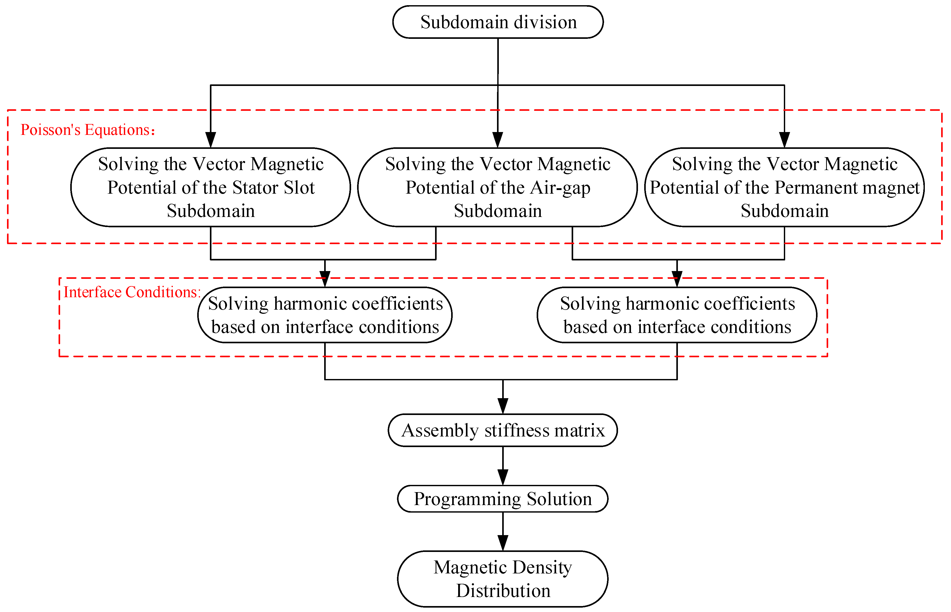
The harmonic coefficients in the three subdomains can be obtained by solving the above formula. In summary, the flow chart of the subdomain analysis method based on the magnetic pole block is shown in Figure 2.

2.4. Air Gap Magnetic Density Distribution

Using the above analysis, according to the principle of vector superposition, the synthetic air gap magnetic field distribution of each permanent magnet block can be obtained. The radial air gap flux density generated by the j th pair of permanent magnet blocks is as follows:
B 2 r j ( r , θ ) = n B 2 r c j n cos ( n p θ ) + n B 2 r s j n sin ( n p θ )
The tangential air gap flux density is as follows:
B 2 θ j ( r , θ ) = n B 2 θ c j n cos ( n p θ ) + n B 2 θ s j n sin ( n p θ )
where:
B 2 r c j n = n = 1 [ R j r · P n p ( r , R 3 ) E n p ( R j , R 3 ) · C 2 n R 3 r · P n p ( r , R j ) E n p ( R j , R 3 ) · D 2 n ]
B 2 r s j n = n = 1 [ R j r · P n p ( r , R 3 ) E n p ( R j , R 3 ) · A 2 n R 3 r · P n p ( r , R j ) E n p ( R j , R 3 ) · B 2 n ]
B 2 θ c j n = n = 1 [ R j r · E n p ( r , R 3 ) E n p ( R j , R 3 ) · A 2 n R 3 r · E n p ( r , R j ) E n p ( R j , R 3 ) · B 2 n ]
B 2 θ s j n = n = 1 [ R j r · E n p ( r , R 3 ) E n p ( R j , R 3 ) · C 2 n R 3 r · E n p ( r , R j ) E n p ( R j , R 3 ) · D 2 n ]
The magnetic density generated by N p pieces of permanent magnets under a pair of magnetic poles is superimposed in the air gap. Then, the air gap magnetic density of the whole permanent magnet pole is as follows:
{ B 2 r ( r , θ ) = j = 1 N p B 2 r j ( r , θ ) B 2 θ ( r , θ ) = j = 1 N p B 2 θ j ( r , θ )
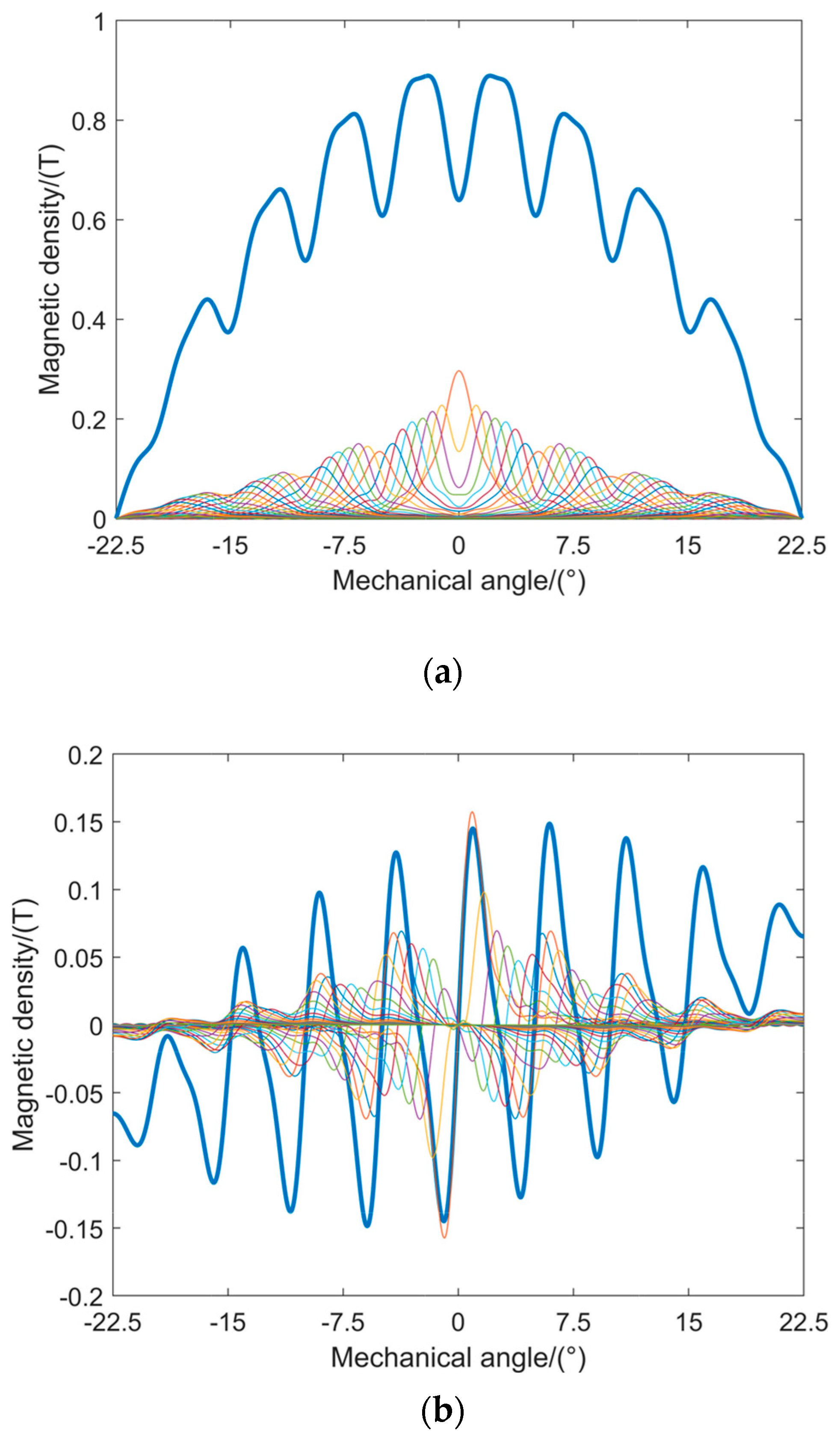
Now, if a pole area is considered with a mechanical angle of 45° when the logarithm of the blocks is 16 (that is, the number of blocks under each pole reaches 32), then the equivalent radius of the equivalent permanent magnet block is very close to the outer diameter of the permanent magnet pole, and the analytical calculation results are accurate enough. Figure 3a,b shows that when N p = 16, the air gap flux density radial component and tangential component generated by each segmented permanent magnet block, and the radial and tangential components of the air gap flux density of the eccentric poles are synthesized.

2.5. Calculation of No-Load back Electromotive Force

According to Formula (87), the radial flux density under one pole at the centerline of the air gap can be obtained. Fourier decomposes the airgap flux density with discrete and dense points and obtains the harmonic components of the air gap flux density including the fundamental wave, and the amplitude of each harmonic flux is as follows:
Φ m n = 2 π B m n l τ n , n / p = 1 , 3 , 5
where, τ is the pole distance, and l is the axial length of the motor.
Then, the effective value E n of each harmonic electromotive force is
E n = 2 π n f W s k w n Φ m n , n / p = 1 , 3 , 5
where, f is the fundamental frequency; W s is the total number of turns in series for each phase; k w n is the winding coefficient of the n th harmonic.

3. Model Calculation and FEM Verification

This study takes an 8-pole 72-slot SPMSM with eccentrically cut poles as an example. The two-dimensional FEM simulation verification of the equal-area block subdomain analytical model proposed in this paper has been carried out. The stator winding is a three-phase open circuit winding, and the stator slot is a rectangular open slot. Table 1 shows some design parameters of the motor.
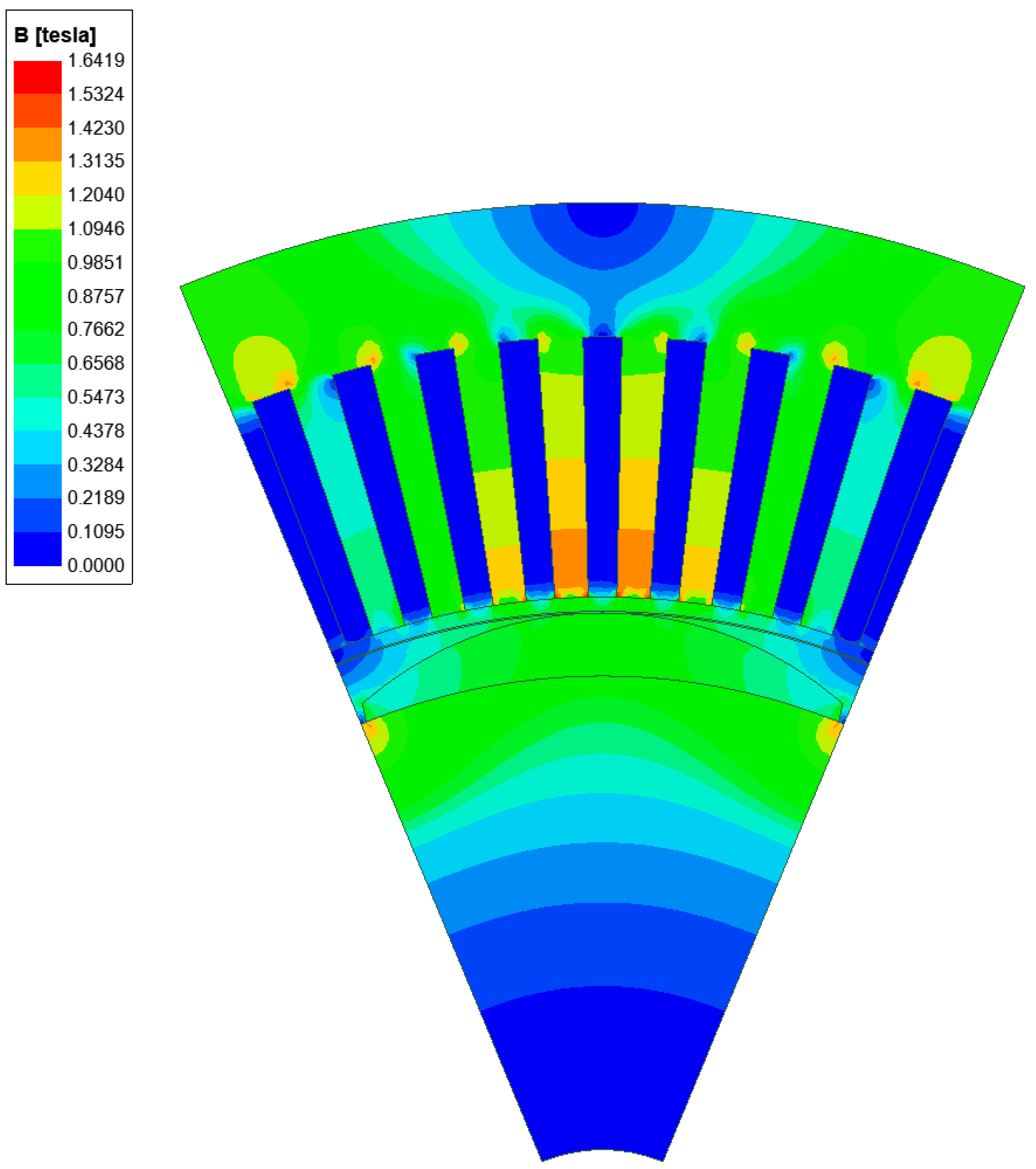
For the permanent magnet poles of the SPMSM with eccentric pole cutting, the outer arc radius of the permanent magnet is 88 mm, the inner arc radius is 80 mm, the maximum thickness of the permanent magnet is 8 mm, the width of the stator slot is 4.2 mm, and the slot depth is 33 mm. An FEM model under the pole is established according to the above parameters, and Figure 4 shows the magnetic density cloud diagram calculated by the FEM. The FEM model is based on the ANSYS Maxwell software platform.
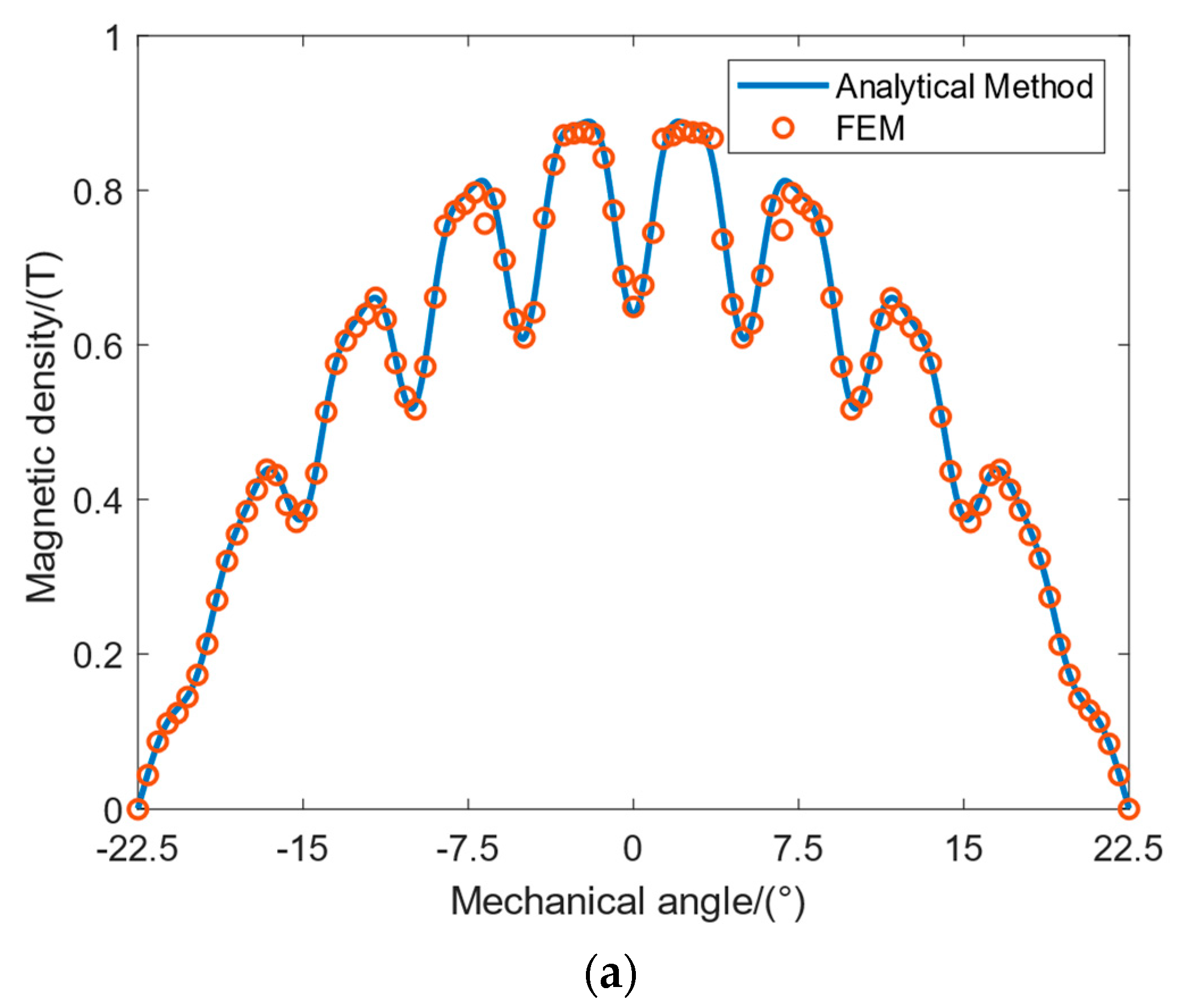
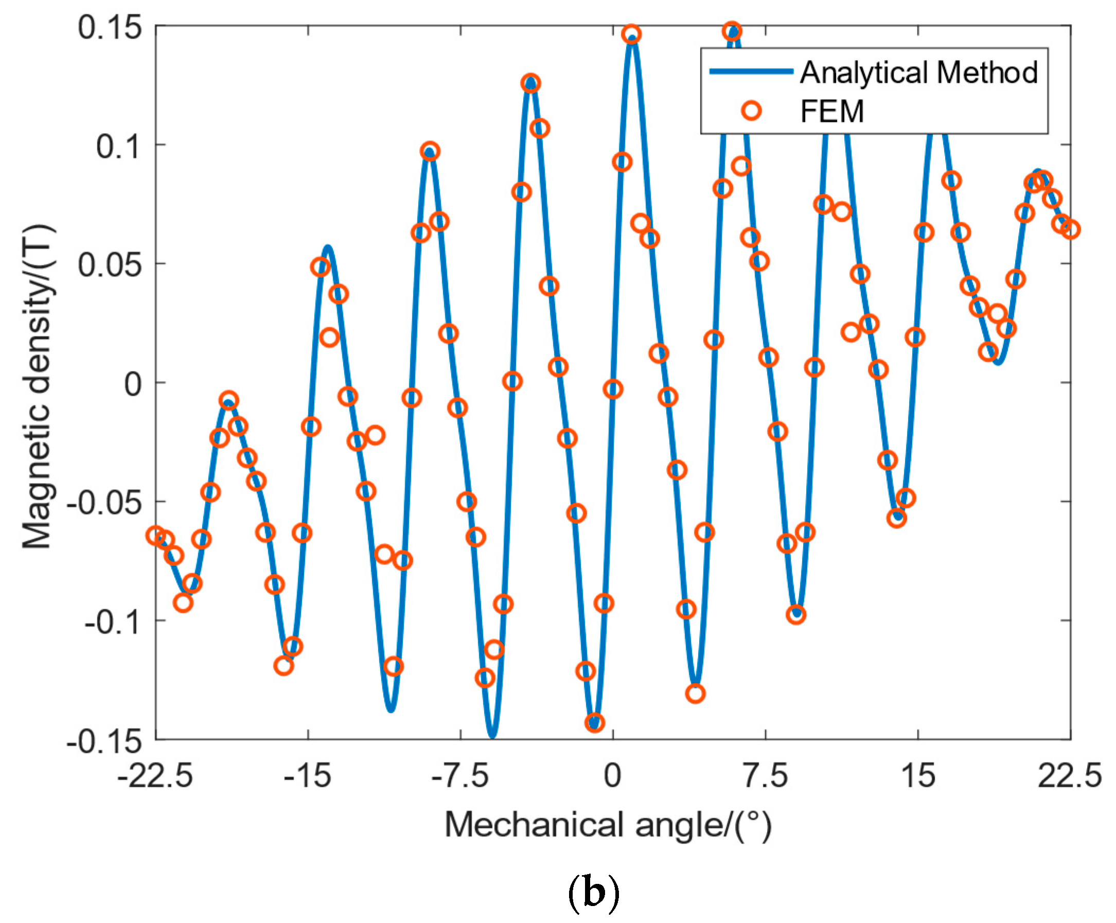
Figure 5 shows the comparison between the calculation results of the equal-area block subdomain model analysis method and the FEM calculation results. The no-load air gap magnetic density calculation results of the two methods are in good agreement.

4. Results and Discussion

Since the analytical results obtained by the subdomain model method are in the form of a series and each series represents a harmonic, the magnitude of the magnetic density harmonic can be obtained directly. There is no need to perform Fourier analysis again on the calculation results of the analytical model.
Table 2 provides a comparison of the computation times of the subdomain analytical method and FEM for the same computer configuration.
Table 3 shows the subdomain model direct calculation of each harmonic flux density component in the air gap under no-load conditions and the calculation results of the FEM. It can be seen from Table 3 that the harmonic components, including the fundamental component, are consistent with the analysis results of the FEM, which shows the accuracy of the solution using the subdomain model. The relative error of the fundamental magnetic density is 0.64%. The stator slots are assumed to be radial open slots when the subdomain model analysis method is used to solve the problem, whereas the FEM is aimed at the actual rectangular open slots, which is the main cause of the error. The calculation results in Table 3 also show that the magnetic density of the 17th and 19th harmonics of the first tooth harmonic is relatively large, which is in line with the design of the open slot. Tooth harmonics can be weakened by taking measures such as rotor skew poles and stator skews.
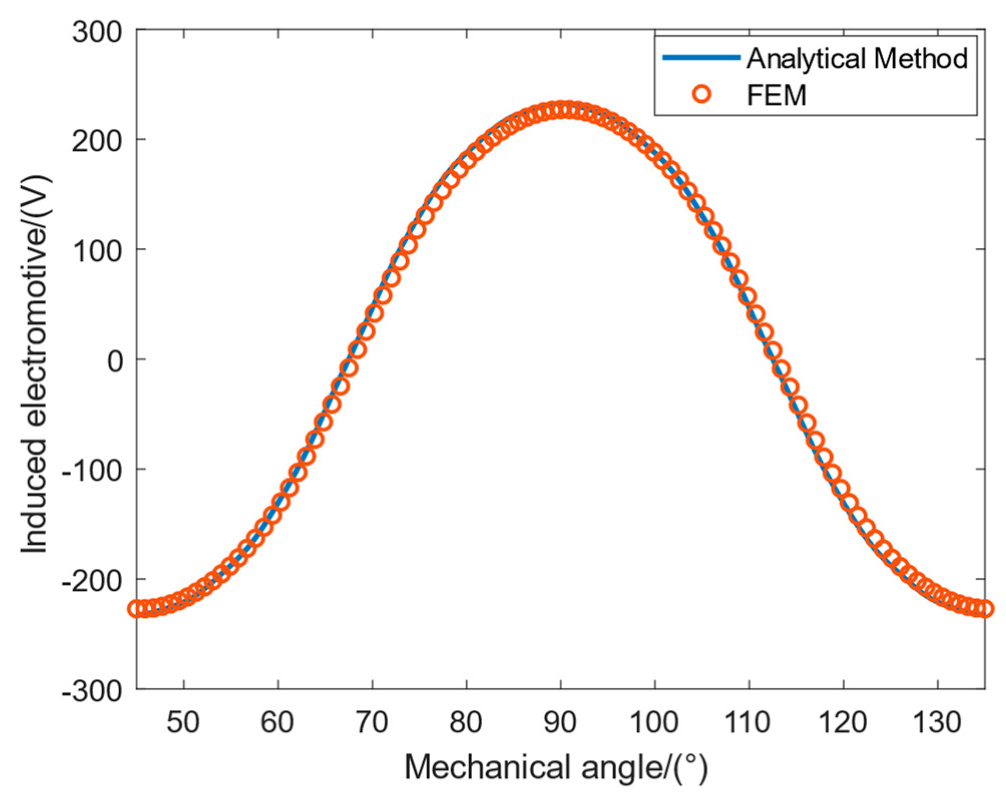
According to the harmonic components of the no-load air gap magnetic field flux density calculated by the analytical method shown in Table 3, each harmonic potential is obtained by Formula (95) and then superimposed on each other, and the no-load induced potential is obtained as shown in Figure 6. Comparing the obtained results with the FEM results, it can still be seen that the consistency between the two is good.

5. Conclusions

In this paper, aiming at the difficulty in analyzing the electromagnetic field of the SPMSM with eccentrically cut poles, based on an accurate subdomain model, an analytical calculation of the equal-area sub-block processing of the magnetic poles is proposed. It not only solves the problem of the unequal thickness of magnetic poles but also considers the influence of stator slotting and actual permanent magnet permeability. The method used can directly obtain the harmonic components of the air gap flux density of the eccentric pole permanent magnet motor from the analytical model, and it is not necessary to perform Fourier decomposition on the result again, which is convenient and quick. To verify the calculation accuracy of the proposed method, the no-load air gap flux density and induced potential are calculated by using the FEM, and the calculation results are consistent with the results of the analytical method used in this paper, thus illustrating the accuracy of the method.
This paper focuses on the no-load magnetic field of the SPMSM with eccentrically cut poles, with the aim of solving the problem that the conventional subdomain resolution method cannot be applied directly to such motors. The proposed method can be used to guide the rapid selection of the design parameters in the initial design stage of the motor. In future works, different winding forms, semi-open slots, and complex structural forms such as rotor diagonal poles will be considered. The magnetic saturation effect at the rated load of the motor will also be studied in depth and more efficient algorithms will be used.

Author Contributions

J.Z.: Conceptualization, data curation, formal analysis, investigation, writing—original draft, methodology; J.H.: funding acquisition, project administration, writing—review and editing; G.G.: writing—review and editing. All authors have read and agreed to the published version of the manuscript; F.D.: funding acquisition, project administration.

Funding

This research received no external funding.

Conflicts of Interest

The authors declare no conflict of interest.

Nomenclature

O 1 Center of the inner arc of the magnetic pole
O 2 Center of the outer arc of the magnetic pole
R 1 Radius of the inner arc of the magnetic pole
R 2 Radius of the outer arc of the magnetic pole
R 3 Radius at the top of the slot
R 4 Radius at the bottom of the slot
R j Radius of the j th magnetic block
φ j Central angle of the magnetic pole of block j th
θ 1 Central angle of the inner arc of the magnetic pole
θ 2 Central angle of the outer arc of the magnetic pole
j Pole block number
p Pairs of poles
N p Total number of blocks for half a magnetic pole
N s Number of stator slots
i Slot number
k Harmonic order in slot
n Harmonic orders in permanent magnet and air gap
μ r Relative permeability of permanent magnet
μ 0 Vacuum permeability
β Central angle corresponding to the slot
γ i Position angle of the center of the i th slot
θ i Starting position of the i th slot
τ Pole distance
l Core axial length(mm)
α p Pole arc coefficient
f Fundamental frequency
W s Total number of turns in series for each phase
k w n Winding coefficient of the n th harmonic

References

  1. Wang, K.; Sun, H.; Zhang, L.; Liu, C.; Zhu, Z. An overview of rotor pole optimization techniques for permanent magnet synchronous machines. Proc. CSEE 2017, 37, 7304–7318. [Google Scholar]
  2. Yang, Y.; Wang, X.; Ding, T. Analysis of the optimization of pole arc combination to reduce the cogging torque in PM machines. Proc. CSEE 2007, 27, 7–11. [Google Scholar]
  3. Hu, P.; Wang, D.; Jin, Q. Sinusoidal optimization model for air gap magnetic field of eccentric magnetic pole permanent magnet machine. Trans. China Electrotech. Soc. 2019, 34, 3759–3768. [Google Scholar]
  4. Hu, P.; Wang, D.; Jing, S. Research on the optimization of harmonic pole shaping technology for arcuate pole permanent magnet motor. Proc. CSEE 2020, 40, 5987–5997. [Google Scholar]
  5. Ho, S. An optimal method for the minimization of cogging torques of a permanent magnet motor using FEM and genetic algorithm. IEEE Trans. Appl. Supercond. 2010, 20, 861–864. [Google Scholar] [CrossRef]
  6. Chen, N.; Ho, S.L.; Fu, W. Optimization of permanent magnet surface shapes of electric motors for minimization of cogging torque Using FEM. IEEE Trans. Magn. 2010, 46, 2478–2481. [Google Scholar] [CrossRef]
  7. Wu, L.; Zhu, Z.; Staton, D. Analytical model of eddy current loss in windings of permanent magnet machines accounting for load. IEEE Trans. Magn. 2012, 48, 2138–2151. [Google Scholar] [CrossRef]
  8. Golovanov, D.; Gerada, C. An analytical subdomain model for dual-rotor permanent magnet motor with halbach array. IEEE Trans. Magn. 2019, 55, 1–4. [Google Scholar] [CrossRef]
  9. Xu, Y.; Wu, Q.; Gong Xiao. Network-varying equivalent magnetic circuit modeling of novel disk transverse-flux permanent magnet brushless machine. Trans. China Electrotech. Soc. 2016, 31, 147–153. [Google Scholar]
  10. Yang, D.; Deng, Z.; Zhang, H. Exact analytical solution of magnetic field in permanent magnet in-wheel motor. Trans. China Electrotech. Soc. 2019, 34, 1423–1433. [Google Scholar]
  11. Zhu, Z.; Wu, L.; Xia, Z. An accurate subdomain model for magnetic field computation in slotted surface-mounted permanent-magnet machines. IEEE Trans. Magn. 2010, 46, 1100–1115. [Google Scholar] [CrossRef]
  12. Wu, L.; Zhu, Z.; Staton, D. An improved subdomain model for predicting magnetic field of surface-mounted permanent magnet machines accounting for tooth-tips. IEEE Trans. Magn. 2011, 47, 1693–1704. [Google Scholar] [CrossRef]
  13. Zhou, Y.; Li, H.; Meng, G. Analytical calculation of magnetic field and cogging torque in surface-mounted permanent-magnet machines accounting for any eccentric rotor shape. IEEE Trans. Ind. Electron. 2015, 62, 3438–3447. [Google Scholar] [CrossRef]
  14. Guo, Y.; Jin, P.; Hou, S. Analytical method for predicting air-gap magnetic field distribution of surface mounted permanent magnet machine with non-concentric magnetic poles. In Proceedings of the 20th International Conference on Electrical Machines and Systems (ICEMS), Sydney, Australia, 11 August 2017. [Google Scholar]
  15. Yang, S.; Xia, C.; Wang, H. Modeling and analyzing for surface mounted permanent magnet machine with segmented pole. Trans. China Electrotech. Soc. 2015, 30, 49–55. [Google Scholar]
  16. Lubin, T.; Mezani, S.; Rezzoug, A. Exact analytical method for magnetic field computation in the air gap of cylindrical electrical machines considering slotting effects. IEEE Trans. Magn. 2010, 46, 1092–1099. [Google Scholar] [CrossRef]
  17. Lubin, T.; Mezani, S.; Rezzoug, A. 2-D exact analytical model for surface-mounted permanent-magnet machines with semi-closed slots. IEEE Trans. Magn. 2011, 47, 479–492. [Google Scholar] [CrossRef]
  18. Jing, L.; Zhang, Y. An exact analytical method for magnetic field computation and electromagnetic torque in a concentric magnetic gear. Proc. CSEE 2012, 32, 139–146. [Google Scholar]
  19. Guo, S.; Zhou, L.; Qi, G. Analytical calculation of electromagnetic performance of dual three-phase permanent magnet synchronous machine. Trans. China Electrotech. Soc. 2014, 29, 17–28. [Google Scholar]
  20. Li, J.; Jing, L.; Zhou, X. Exact analytical method for surface-mounted permanent-magnet brushless machines. Trans. China Electrotech. Soc. 2012, 27, 83–88. [Google Scholar]
  21. Hu, H. Electromagnetic Analysis and Optimal Design of the Permanent Magnet Synchronous Machine Based on the Exact Subdomain Method. Ph.D. Thesis, Beijing Institute of Technology, Beijing, China, 2017. [Google Scholar]
  22. Ma, Z.; Qi, Z.; Wang, S.; Jing, Y.; He, B.; Cao, H. Multi-Objective Optimization of Outer Rotor Hub Permanent Magnet Synchronous Motor Based on Global Analytical Method. Electr. Mach. Control. Appl. 2023, 50, 44–54. [Google Scholar]
  23. Zhang, S.; Guo, S. Analytical Magnetic Field Method of Permanent Magnet Synchronous Machine Considering Step-Skewed Magnets and Magnetic Slot Wedge. Trans. China Electrotech. Soc. 2019, 34, 11–22. [Google Scholar]
  24. Yang, Y.; Liu, G.; Chen, P.; Yang, X. Electromagnetic performance investigation of vernier hybrid machine. Electr. Mach. Control 2019, 23, 9–17. [Google Scholar]
  25. Yu, Z.; Li, Y.; Jing, Y.; Du, J.; Wang, Z. No-Load Characteristic Analysis of Surface-Mounted Permanent Magnet Synchronous Motor with Non-Concentric Pole Based on Hybrid Magnetic Field Analysis Method. Trans. China Electrotech. Soc. 2020, 35, 3811–3820. [Google Scholar]
  26. Liang, P.; Chai, F. Analytical Prediction of Magnetic Field Distribution in Spoke-Type Permanent-Magnet Synchronous Machines Accounting for Bridge Saturation and Magnet Shape. IEEE Trans. Ind. Electron. 2017, 64, 3479–3488. [Google Scholar] [CrossRef]
  27. Zhao, S.; Chen, J.; Zhang, C.; Li, Z.; Meng, Y. Analytical Calculation of Magnetic Field of Permanent Magnet Synchronous Motor with Uneven Air Gap Structure. Trans. China Electrotech. Soc. 2022, 37, 3502–3513. [Google Scholar]
  28. Li, J.; Wu, X.; Chen, C. Analytical Calculation of Air Gap Magnetic Field for Permanent Magnet Machines Based on Pole Partition Processing. Proc. CSEE 2021, 41, 6390–6399. [Google Scholar]
  29. Pourahmadi-Nakhli, M.; Rahideh, A.; Mardaneh, M. Analytical 2-D Model of Slotted Brushless Machines With Cubic Spoke-Type Permanent Magnets. IEEE Trans. Energy Convers. 2018, 33, 373–382. [Google Scholar] [CrossRef]
  30. Wu, L.; Zhu, M.; Wang, D.; Fang, Y. A Subdomain Model for Open-Circuit Field Prediction in Dual-Stator Consequent-Pole Permanent Magnet Machines. IEEE Trans. Magn. 2019, 55, 1–12. [Google Scholar] [CrossRef]
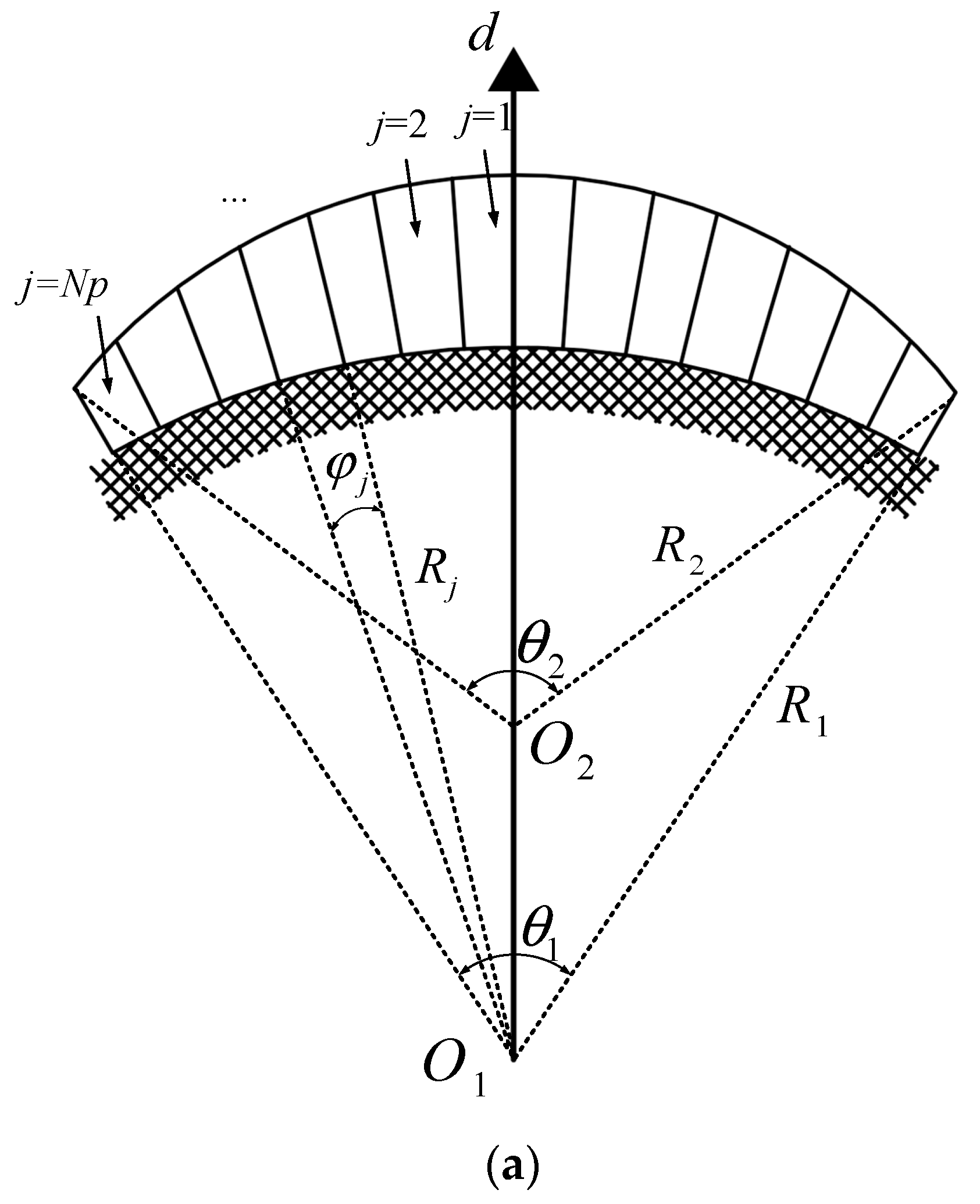
Figure 1. (a) Schematic diagram of the block method of eccentrically cut poles. (b) Cross-sectional view of SPMSM with eccentrically cut poles.
Energies 16 04450 g001aEnergies 16 04450 g001b
Figure 2. Flow chart of the subdomain analysis method.
Energies 16 04450 g002
Figure 3. (a) Diagram of the magnetic density produced by each small pole block and the radial component of the resultant magnetic density. (b) Diagram of the magnetic density produced by each small pole block and the tangential component of the resultant magnetic density.
Energies 16 04450 g003
Figure 4. Magnetic flux density diagram of SPMSM with eccentrically cut poles.
Energies 16 04450 g004
Figure 5. (a) The comparison between the calculation results of the no-load air gap flux density radial component analytical method and the FEM calculation results. (b) The comparison between the calculation results of the no-load air gap flux density tangential component analytical method and the FEM calculation results.
Energies 16 04450 g005aEnergies 16 04450 g005b
Figure 6. Induced electromotive force.
Energies 16 04450 g006
Table 1. Design parameters of SPMSM with eccentrically cut poles of different thicknesses.
ParameterValueParameterValue
Phase m3Stator outer diameter D1/mm290
Rated voltage UN/V234Stator inner diameter Di1/mm180
Pairs of poles P4Rotor outer diameter D2/mm176
Rated speed n1/rpm750Rotor inner diameter Di2/mm80
Permanent magnet materialSmCo30Core Axial Length l/mm88
Pole arc coefficient αp0.978Number of stator slots Ns72
Table 2. Comparison of the calculation of subdomain analytical method and FEM.
ItemsAnalytical MethodFEM
CPUIntel(R) Core(TM) i7-10750 H CPU @ 2.60 GHz
Number of equations/matrixes179236,118
Mesh accuracy-1 mm
Number of subdomains/triangles318,124
Elapsed time8.7 s249 s
Table 3. Comparison of each harmonic component of air gap magnetic field flux density.
Harmonic OrderAnalytical MethodFEA
10.8391 T0.8338 T
30.0516 T0.0591 T
50.0118 T0.0125 T
70.0078 T0.0077 T
90.0032 T0.0026 T
110.0002 T0.0002 T
170.0666 T0.0646 T
190.0635 T0.0612 T
Disclaimer/Publisher’s Note: The statements, opinions and data contained in all publications are solely those of the individual author(s) and contributor(s) and not of MDPI and/or the editor(s). MDPI and/or the editor(s) disclaim responsibility for any injury to people or property resulting from any ideas, methods, instructions or products referred to in the content.