
Enhanced Power Quality in Single-Phase Grid-Connected Photovoltaic Systems: An Experimental Study


 ,
,  ,
,
Abstract
:1. Introduction
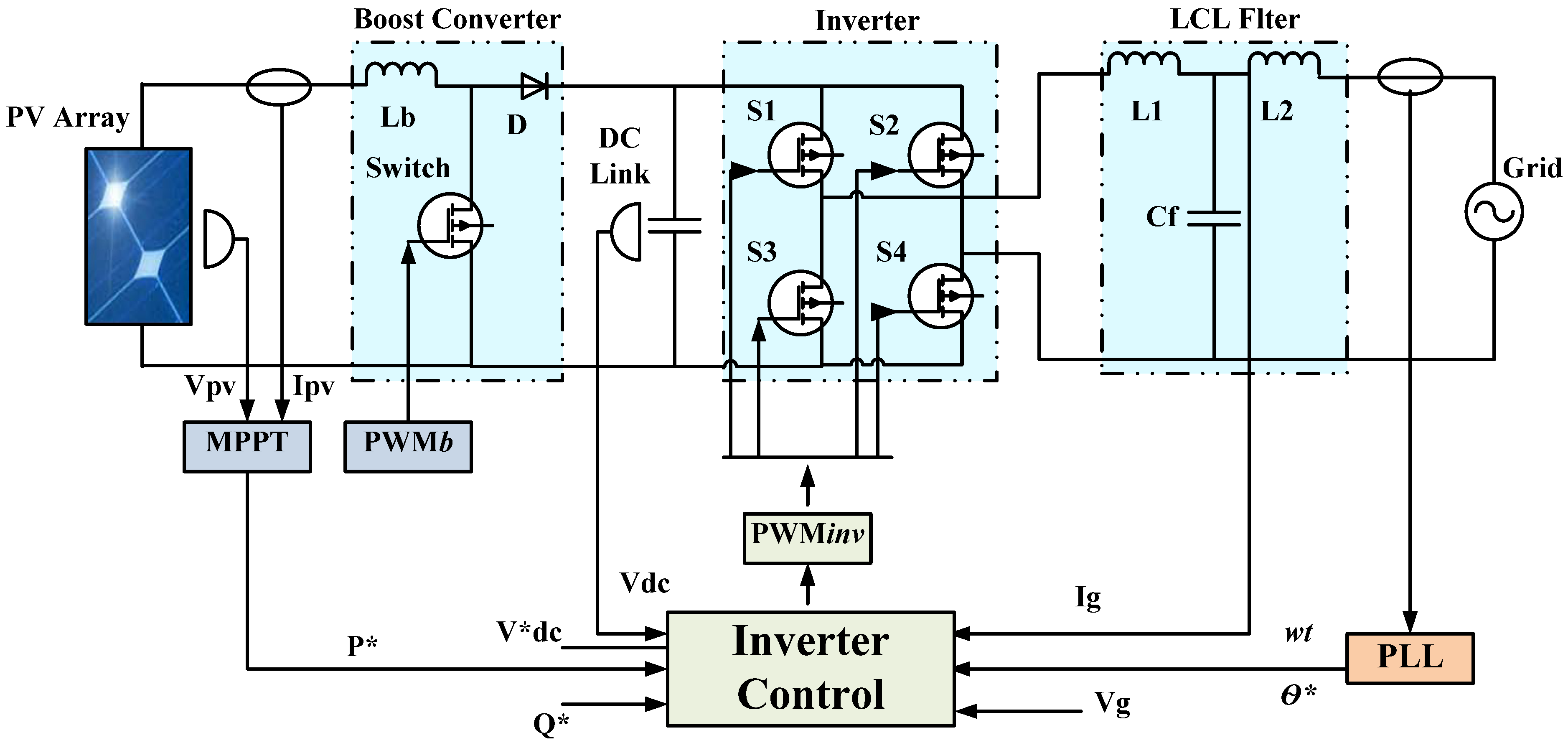
2. Description of the System
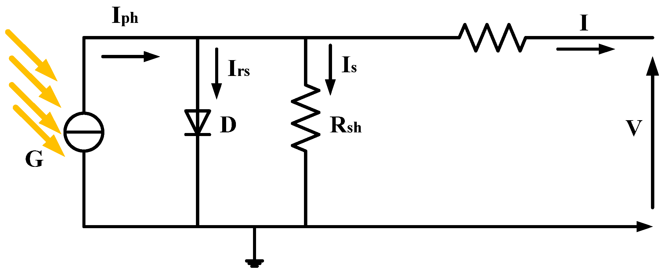
3. PV Array Modeling
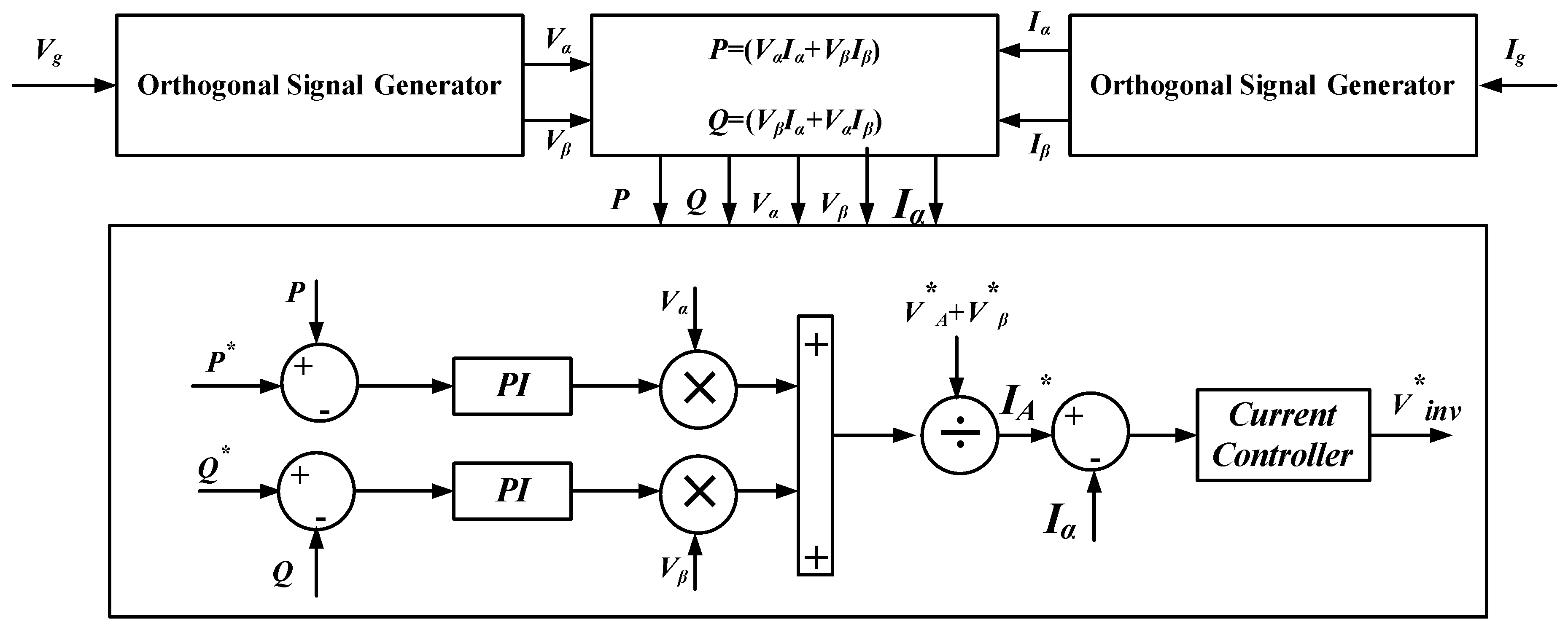
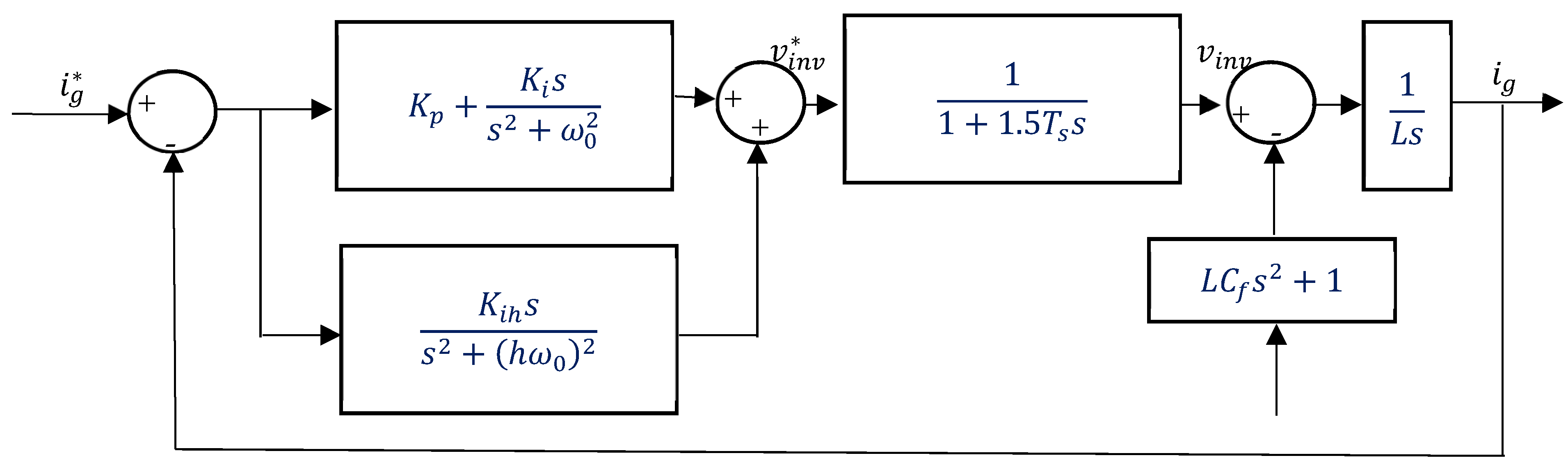
4. Analysis of Power Control
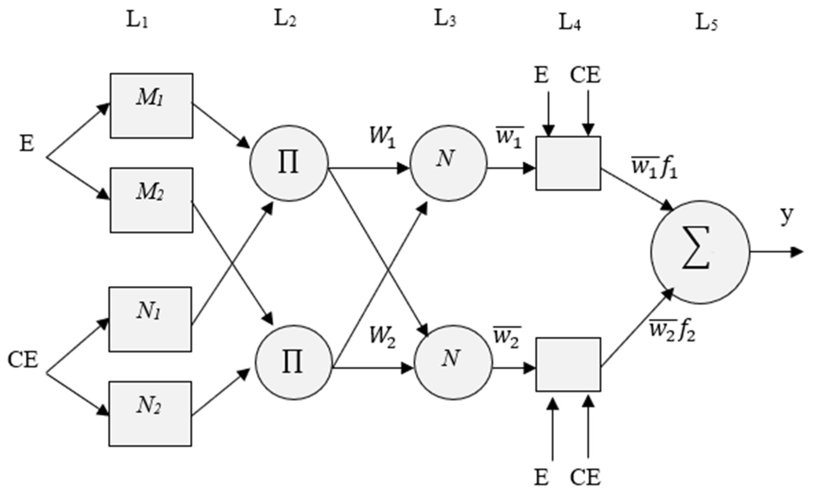
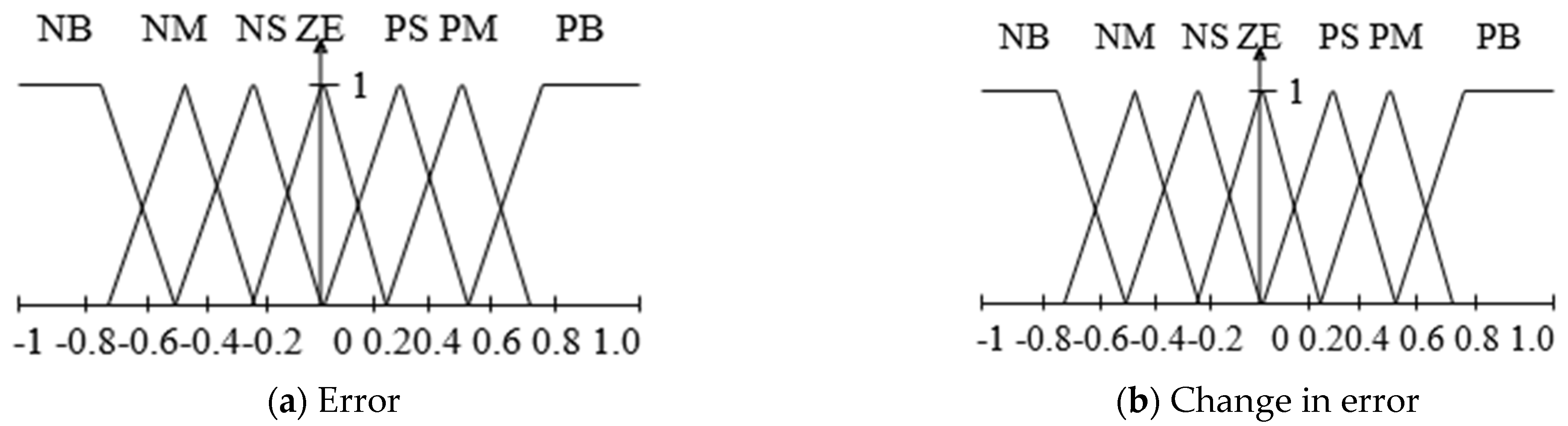
5. ANFIS-Based Controller Development
6. Grid Synchronization Techniques
- Mathematical methods, e.g., synchronized Fourier- and PLL-based methods. Currently, PLL-based synchronization techniques are the most popular choices since the design of a phase detector, a simple sinusoidal multiplier [38,39]. In a single-phase system, however, this procedure will result in a double-frequency term. Another approach to removing phase error for a PLL-based method is to apply the Park transform to an OSG system. A PLL based on T/4 delay [37] and inverse Park transform-based PLL (IPT-PLL) [40] are examples of such PLLs.
- Another approach is to employ adaptive filters that can automatically modify the output. The OSG is utilized to help in the calculations of active and reactive powers and provides appropriate grid synchronization. The OSG system is used to calculate and . Figure 7 depicts the OSG for a single-phase system [7].
7. Simulation Results
8. Experimental Results
- SEMIKRON IGBT based inverter;
- Current and voltage sensors;
- DC-DC boost converter;
- Linear load;
- dSPACE DS 1104 and power quality analyzer;
- Host PC and oscilloscope;
- Five PV panels.
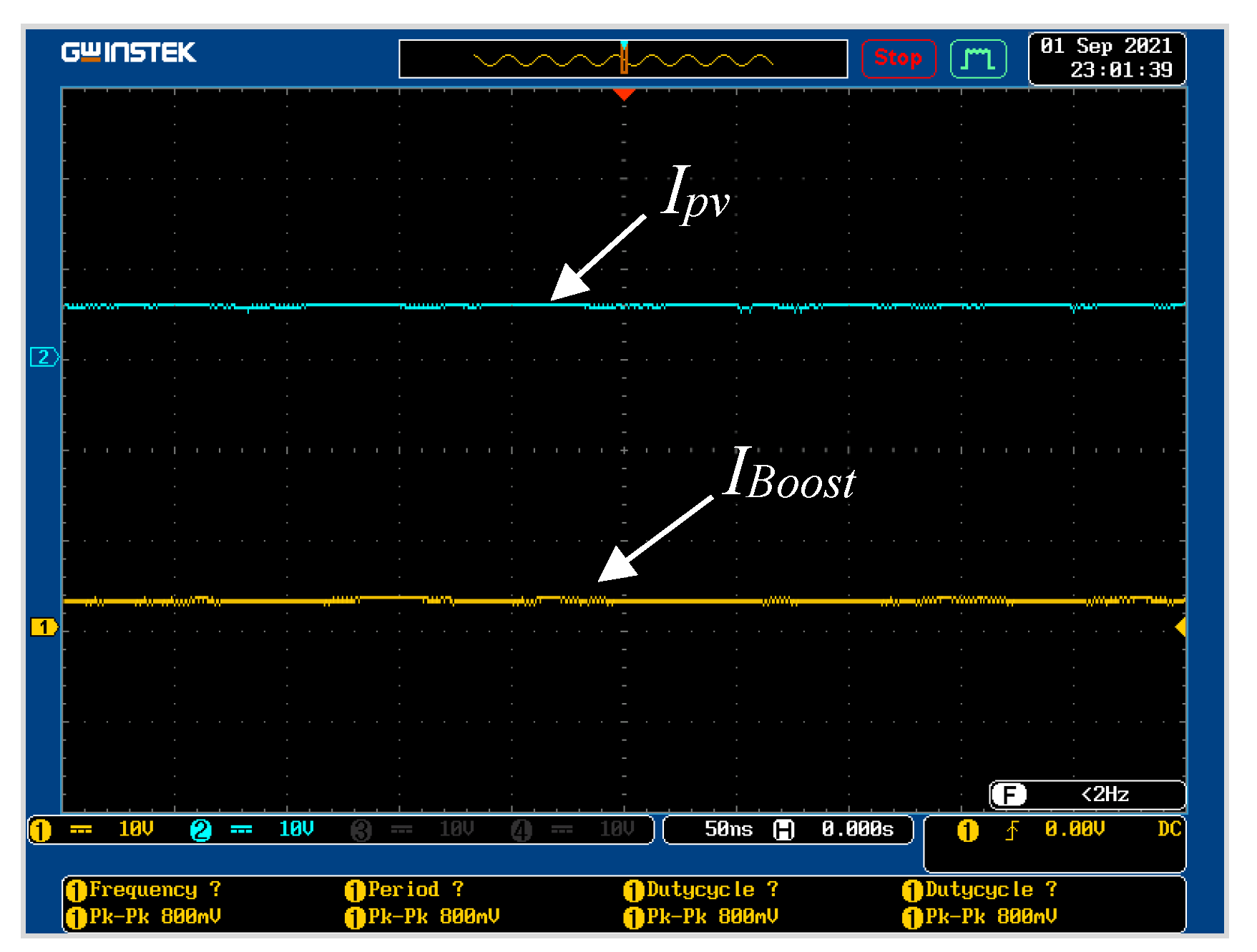
8.1. Islanding Mode
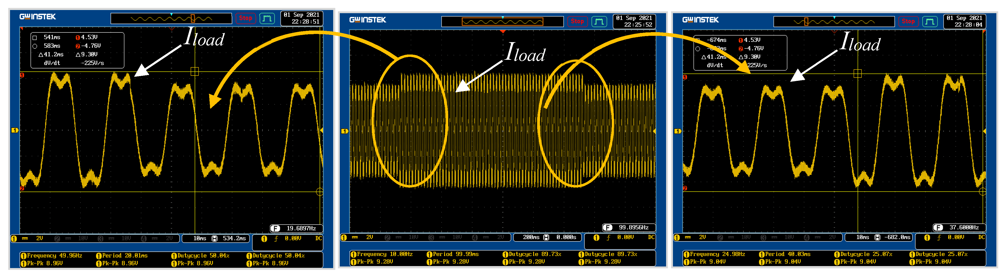
8.2. Load Mode as Supplied Solely by the Grid
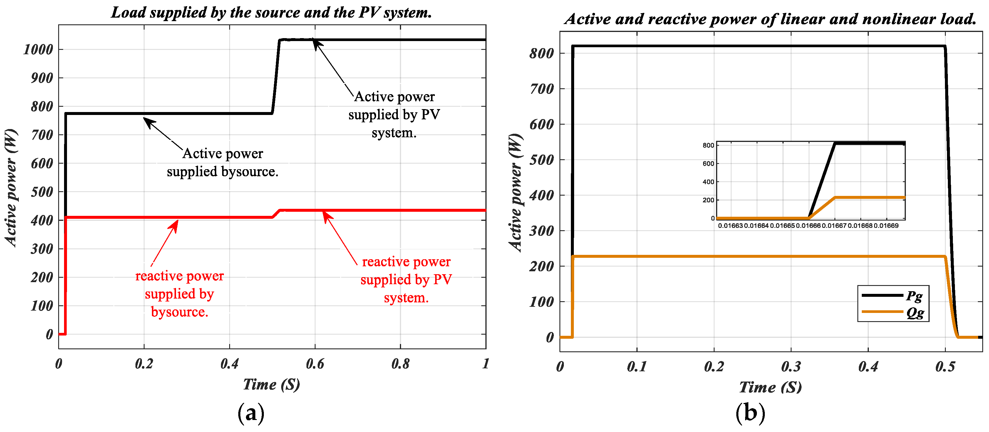
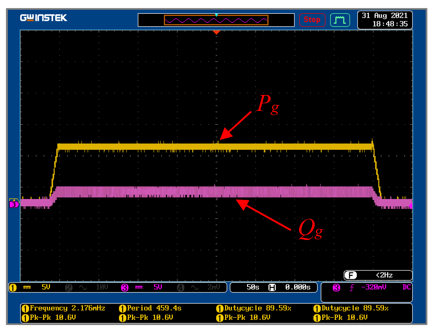
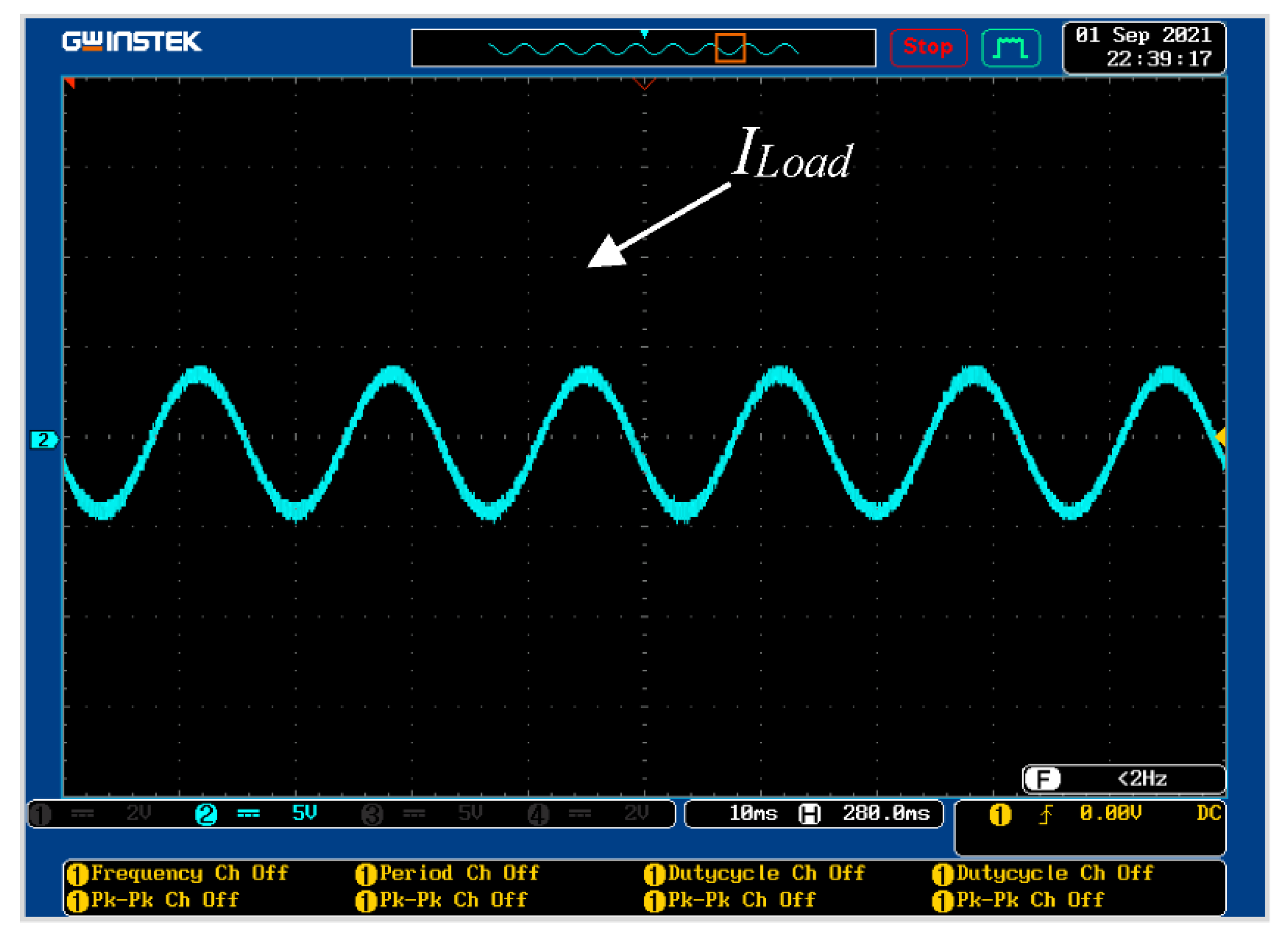
8.3. Load Mode as Supplied by the Grid and PV System
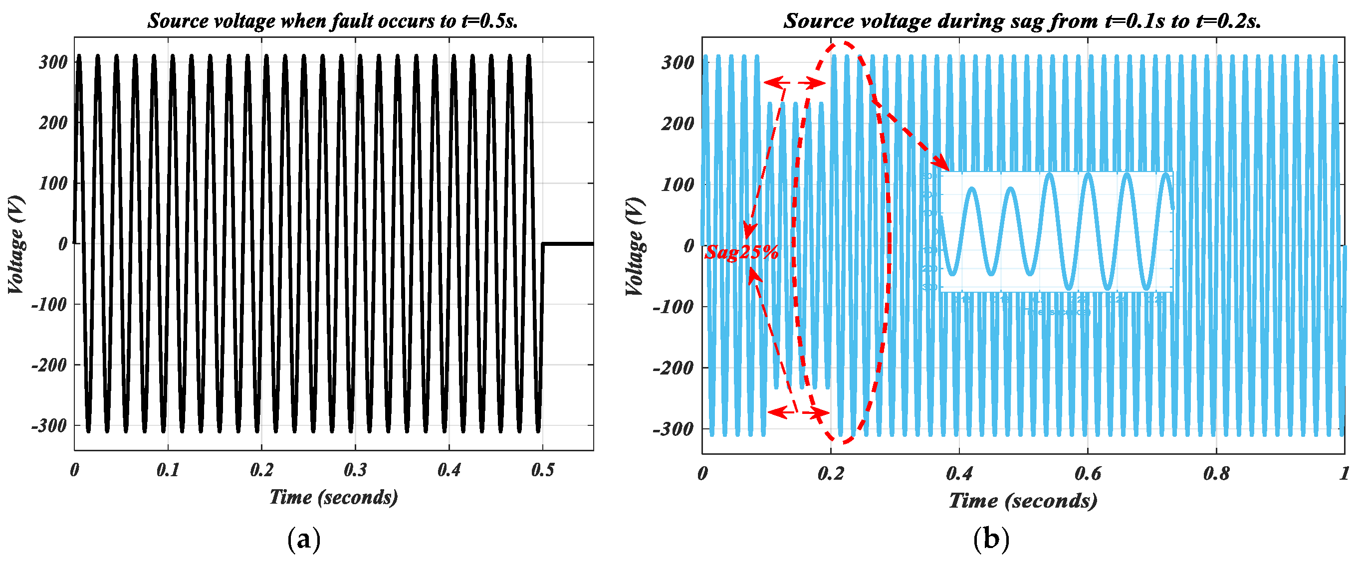
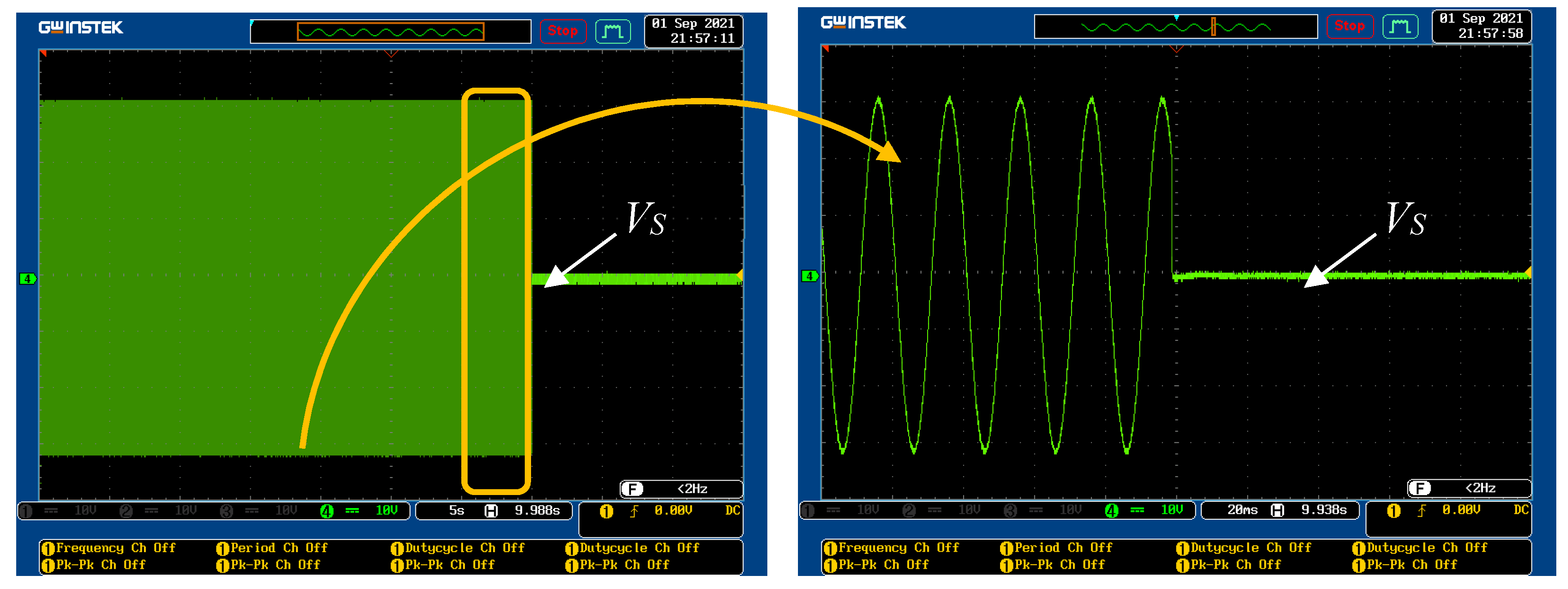
8.4. Voltage Sag Mode
9. Conclusions
Author Contributions
Funding
Data Availability Statement
Acknowledgments
Conflicts of Interest
Abbreviations
| PV | Photovoltaic |
| PWM | Pulse width modulation |
| MPPT | Maximum power point tracking |
| ANFIS | Adaptive neuro-fuzzy inference |
| OSG | Orthogonal signal generator |
| THD | Total harmonic distortion |
| PCC | Point of common coupling |
| PQ | Power quality |
| PLL | phase-locked loops |
| LP | Low pass filter |
| FRT | Fault ride-through |
| P&O | Perturb and observe |
| IPV, VPV | PV array current and voltage |
| and | Grid current and voltage |
| The real and reactive powers | |
| h | Harmonic order |
| ω0 | Fundamental frequency |
| 𝑇𝑠 | Sampling period |
| PMPP | PV array MPP power |
| N | strings of PV |
Appendix A
- Rule1:
- IF ‘E’ is E1 and ‘CE’ is EC1 Then
- Rule1:
- IF ‘E’ is E2 and ‘CE’ is EC2 Then

| Nomenclature | Value |
|---|---|
| TDPs | 350,000 |
| CDP | 60,000 |
| MF | 7 |
| Nodal points | 131 |
| NP | 42 |
| LP | 49 |
| TP | 91 |
| FR | 49 |
| NE | 150 |
Appendix B
| CE E | EC1 | EC2 | EC3 | EC4 | EC5 | EC6 | EC7 |
|---|---|---|---|---|---|---|---|
| E1 | −0.5 | −0.3 | −0.0030 | 0 | 0 | 0 | 0 |
| E2 | −0.35 | −0.14 | 0.07 | 0 | 0 | 0 | 0 |
| E3 | 0 | 0.07 | 0.28 | 0.42 | −0.02 | 0 | 0 |
| E4 | 0 | 0 | 0.5 | 0.7 | 0.5 | −0.06 | 0 |
| E5 | 0 | 0 | 0 | 1.2 | 0.9 | 1.06 | 0.01 |
| E6 | 0 | 0 | 0 | 0 | 0.9 | 0.9 | 1.3 |
| E7 | 0 | 1.1 | 0.6 | 0 | 0 | 0.6 | 0.9 |
Appendix C

References
- Dugan, R.C.; Mc Granaghan, M.F.; Beaty, H.W. Electrical Power Systems Quality; McGraw-Hill: New York, NY, USA, 1996. [Google Scholar]
- Farhadi-Kangarlu, M.; Babaei, E.; Blaabjerg, F. A comprehensive review of dynamic voltage restorers. Int. J. Electr. Power Energy Syst. 2017, 92, 136–155. [Google Scholar] [CrossRef]
- Sankaren, C. Power Quality; CRC Press: Boca Raton, FL, USA, 2017. [Google Scholar]
- IEEE Std. 1346-1998; IEEE Recommended Practice for Evaluating Electric Power System Compatibility with Electronic Process Equipment. IEEE: Piscataway, NJ, USA, 1998.
- IEC Std. 61000-2-1; Electromagnetic Compatibility (EMC), Part 2: Environment, Section 1: Description of the Environment, Electromagnetic Environment for Low-Frequency Conducted Disturbances and Signaling in Public Power Supply Systems. IEC: Geneva, Switzerland, 1990.
- Rauf, A.M.; Khadkikar, V. Integrated photovoltaic and dynamic voltage restorer system configuration. IEEE Trans. Sustain. Energy 2015, 6, 400–410. [Google Scholar] [CrossRef]
- Kusko, A. Power Quality in Electrical Systems; McGraw-Hill Education: New York, NY, USA, 2007. [Google Scholar]
- Gotekar, P.S.; Muley, S.P.; Kothari, D.P. A Single Phase Grid Connected PV System working in Different Modes. Eng. Technol. Appl. Sci. Res. 2020, 10, 6374–6379. [Google Scholar] [CrossRef]
- Proceedings of the 27th Conference of the Parties to the United Nations Framework Convention on Climate Change, COP27, Sharm el-Sheikh, Egypt, 6–20 November 2022; Available online: https://www.un.org/en/climatechange/cop27 (accessed on 8 May 2023).
- Shukhobodskiy, A.A.; Colantuono, G. RED WoLF: Combining a battery and thermal energy reservoirs as a hybrid storage system. Appl. Energy 2020, 274, 115209. [Google Scholar] [CrossRef]
- Toosi, H.A.; Del Pero, C.; Leonforte, F.; Lavagna, M.; Aste, N. Machine learning for performance prediction in smart buildings: Photovoltaic self-consumption and life cycle cost optimization. Appl. Energy 2023, 334, 120648. [Google Scholar] [CrossRef]
- Teodorescu, R.; Liserre, M.; Rodríguez, P. Grid Converters for Photovoltaic and Wind Power Systems; John Wiley & Sons: Chichester, UK, 2011. [Google Scholar]
- Mahamudul, H.; Saad, M.; Henk, M.I. Photovoltaic system modeling with fuzzy logic based maximum power point tracking algorithm. Int. J. Photoenergy 2013, 2013, 762946. [Google Scholar] [CrossRef] [Green Version]
- Sangwongwanich, A.; Blaabjerg, F. Mitigation of interharmonics in PV systems with maximum power point tracking modification. IEEE Trans. Power Electron. 2019, 34, 8279–8282. [Google Scholar] [CrossRef] [Green Version]
- Gotekar, P.S.; Muley, S.P.; Kothari, D.P. Fuzzy Inference based control of single phase grid connected photovoltaic system. In Proceedings of the 2019 Innovations in Power and Advanced Computing Technologies (i-PACT), Vellore, India, 22–23 March 2019; pp. 1–3. [Google Scholar]
- Vosoughi, N.; Hosseini, S.H.; Sabahi, M. Single-phase common-grounded transformer-less grid-tied inverter for PV application. IET Power Electron. 2020, 13, 157–167. [Google Scholar] [CrossRef]
- Ghosh, S.S.; Nathan, K.S.; Siwakoti, Y.P.; Long, T. Dual polarity DC–DC converter integrated grid-tied single-phase transformer less inverter for solar application. J. Eng. 2019, 2019, 3962–3966. [Google Scholar] [CrossRef]
- Datta, A.; Sarker, R.; Hazarika, I. An efficient technique using modified p–q theory for controlling power flow in a single-stage single-phase grid-connected PV system. IEEE Trans. Ind. Inform. 2018, 15, 4635–4645. [Google Scholar] [CrossRef]
- Anurag, A.; Yang, Y.; Blaabjerg, F. Thermal performance and reliability analysis of single-phase PV inverters with reactive power injection outside feed-in operating hours. IEEE J. Emerg. Sel. Top. Power Electron. 2015, 3, 870–880. [Google Scholar] [CrossRef]
- Yang, Y.; Wang, H.; Blaabjerg, F. Reactive power injection strategies for single-phase photovoltaic systems considering grid requirements. IEEE Trans. Ind. Appl. 2014, 50, 4065–4076. [Google Scholar] [CrossRef] [Green Version]
- Yang, Y.; Blaabjerg, F.; Zou, Z. Benchmarking of grid fault modes in single-phase grid-connected photovoltaic systems. IEEE Trans. Ind. Appl. 2013, 49, 2167–2176. [Google Scholar] [CrossRef] [Green Version]
- Yang, Y.; Blaabjerg, F. Low-voltage ride-through capability of a single-stage single-phase photovoltaic system connected to the low-voltage grid. Int. J. Photoenergy 2013, 2013, 257487. [Google Scholar] [CrossRef] [Green Version]
- Ikken, N.; Bouknadel, A.; Haddou, A.; Tariba, N.-E.; El Omari, H.; El Omari, H. PLL synchronization method based on second-order generalized integrator for single phase grid connected inverters systems during grid abnormalities. In Proceedings of the 2019 International Conference on Wireless Technologies, Embedded and Intelligent Systems (WITS), Fez, Morocco, 3–4 April 2019; pp. 1–5. [Google Scholar]
- Butt, H.Z.; Awon, M.; Khalid, H.A. Performance Analysis of a Continuous and Discretized Second Order Generalized Integrator based Phase Lock Loop for Single Phase Grid Connected PV Systems. In Proceedings of the 2018 International Conference on Power Generation Systems and Renewable Energy Technologies (PGSRET), Islamabad, Pakistan, 10–12 September 2018; pp. 1–6. [Google Scholar]
- Panda, A.K.; Patnaik, N. Combined operation of a new power angle control unit vector template based unified power quality conditioner and fuel cell stack supply with effective utilization of shunt and series inverter. Electr. Power Compon. Syst. 2016, 44, 2048–2058. [Google Scholar] [CrossRef]
- Nouaiti, A.; Mesbahi, A.; Saad, A.; Khafallah, M.; Reddak, M. Realization of a Single-Phase Multilevel Inverter for Grid-Connected Photovoltaic System. Eng. Technol. Appl. Sci. Res. 2018, 8, 3344–3349. [Google Scholar] [CrossRef]
- Krithiga, S.; Gounden, N.G.A. Power electronic configuration for the operation of PV system in combined grid-connected and stand-alone modes. IET Power Electron. 2014, 7, 640–647. [Google Scholar] [CrossRef]
- Subudhi, P.S.; Krithiga, S. PV and grid interfaced plug-in EV battery charger operating in P-VG PV and VG modes. Int. J. Recent Technol. Eng. 2019, 8, 3431–3443. [Google Scholar] [CrossRef]
- Reddy, V.R.; Sreeraj, E.S. A feedback-based passive islanding detection technique for one-cycle-controlled single-phase inverter used in photovoltaic systems. IEEE Trans. Ind. Electron. 2019, 67, 6541–6549. [Google Scholar] [CrossRef]
- Raza, S.A.; Jiang, J. A benchmark distribution system for investigation of residential microgrids with multiple local generation and storage devices. IEEE Open Access J. Power Energy 2019, 7, 41–50. [Google Scholar] [CrossRef]
- Lam, L.H.; Phuc, T.D.H.; Hieu, N.H. Simulation models for three-phase grid connected PV inverters enabling current limitation under unbalanced faults. Eng. Technol. Appl. Sci. Res. 2020, 10, 5396–5401. [Google Scholar] [CrossRef]
- Jamil, M.; Rizwan, M.; Kothari, D.P. Grid Integration of Solar Photovoltaic Systems; CRC Press: Boca Raton, FL, USA, 2017. [Google Scholar]
- Kazmierkowski, M.P. Renewable Energy Devices and Systems with Simulations in MATLAB and ANSYS [Book News]. IEEE Ind. Electron. Mag. 2018, 12, 80–83. [Google Scholar] [CrossRef]
- Hasanien, H.M. An adaptive control strategy for low voltage ride through capability enhancement of grid-connected photovoltaic power plants. IEEE Trans. Power Syst. 2015, 31, 3230–3237. [Google Scholar] [CrossRef]
- Cárdenas, R.; Díaz, M.; Rojas, F.; Clare, J.; Wheeler, P. Resonant control system for low-voltage ride-through in wind energy conversion systems. IET Power Electron. 2016, 9, 1297–1305. [Google Scholar] [CrossRef]
- Ben Abdelkader, A.; Toumi, T.; Abdelkhalek, O. Experimental verification of dynamic voltage restorer fed by solar PV: Lithium-ion battery storage for lasting power quality improvement. Electr. Eng. 2022, 104, 4581–4593. [Google Scholar] [CrossRef]
- Hossain, M.K.; Ali, M.H. Fuzzy logic controlled power balancing for low voltage ride-through capability enhancement of large-scale grid-connected PV plants. In Proceedings of the 2017 IEEE Texas Power and Energy Conference (TPEC), College Station, TX, USA, 9–10 February 2017; pp. 1–6. [Google Scholar]
- Lin, F.-J.; Lu, K.-C.; Ke, T.-H.; Yang, B.-H.; Chang, Y.-R. Reactive power control of three-phase grid-connected PV system during grid faults using Takagi–Sugeno–Kang probabilistic fuzzy neural network control. IEEE Trans. Ind. Electron. 2015, 62, 5516–5528. [Google Scholar] [CrossRef]
- Toumi, T.; Allali, A.; Meftouhi, A.; Abdelkhalek, O.; Benabdelkader, A.; Denai, M. Robust control of series active power filters for power quality enhancement in distribution grids: Simulation and experimental validation. ISA Trans. 2020, 107, 350–359. [Google Scholar] [CrossRef]
- Al-Durra, A.; Fayyad, Y.; Muyeen, S.; Blaabjerg, F. Fault ride-through of a grid-connected photovoltaic system with quasi Z source inverter. Electr. Power Compon. Syst. 2016, 44, 1786–1800. [Google Scholar] [CrossRef] [Green Version]
- Bae, Y.; Vu, T.-K.; Kim, R.-Y. Implemental control strategy for grid stabilization of grid-connected PV system based on German grid code in symmetrical low-to-medium voltage network. IEEE Trans. Energy Convers. 2013, 28, 619–631. [Google Scholar] [CrossRef]
- Blaabjerg, F.; Teodorescu, R.; Liserre, M.; Timbus, A.V. Overview of control and grid synchronization for distributed power generation systems. IEEE Trans. Ind. Electron. 2006, 53, 1398–1409. [Google Scholar] [CrossRef] [Green Version]
- Hasaneen, M.M.; Badr, M.A.; Atallah, A.M. Control of active/reactive power and low-voltage ride through for 40 kW three-phase grid-connected single-stage PV system. CIRED-Open Access Proc. J. 2017, 2017, 1655–1659. [Google Scholar] [CrossRef]
- Hossain, M.K.; Ali, M.H. Low voltage ride through capability enhancement of grid connected PV system by SDBR. In Proceedings of the 2014 IEEE PES T&D Conference and Exposition, Medellin, Colombia, 10–13 September 2014; pp. 1–5. [Google Scholar]
- Worku, M.Y.; Abido, M.A. Grid-connected PV array with supercapacitor energy storage system for fault ride through. In Proceedings of the 2015 IEEE International Conference on Industrial Technology (ICIT), Seville, Spain, 17–19 March 2015; pp. 2901–2906. [Google Scholar]
- Bighash, E.Z.; Sadeghzadeh, S.M.; Ebrahimzadeh, E.; Blaabjerg, F. Improving performance of LVRT capability in single-phase grid-tied PV inverters by a model-predictive controller. Int. J. Electr. Power Energy Syst. 2018, 98, 176–188. [Google Scholar] [CrossRef]


| Component | Value |
|---|---|
| PV panel maximum power | |
| LC filter values | 2.3 mH, 100 KF |
| Linear load | 450 W, 125 Var |
| Nonlinear load | 850 W, 250 Var |
| Converter values | 2.9 mH, 70 KF, 15 kHz |
| Ref. | Year | Method | Merits/Disadvantages |
|---|---|---|---|
| [41] | 2017 | Conventional PQ control method |
|
| [42] | 2015 | CMPN-based PI controller |
|
| [43] | 2016 | Resonant controller |
|
| [34] | 2014 | Dynamic resistor braking |
|
| [35] | 2016 | Quasi Z-source inverter |
|
| [44] | 2015 | Energy storage system in supercapacitor |
|
| [36] | 2019 | Conventional PI-based PQ control |
|
| [40] | 2018 | Model predictive control approach |
|
| [45] | 2017 | Fault ride in control based on fuzzy logic |
|
| [46] | 2015 | Probabilistic wavelet fuzzy-based neural network controller |
|
Disclaimer/Publisher’s Note: The statements, opinions and data contained in all publications are solely those of the individual author(s) and contributor(s) and not of MDPI and/or the editor(s). MDPI and/or the editor(s) disclaim responsibility for any injury to people or property resulting from any ideas, methods, instructions or products referred to in the content. |
© 2023 by the authors. Licensee MDPI, Basel, Switzerland. This article is an open access article distributed under the terms and conditions of the Creative Commons Attribution (CC BY) license (https://creativecommons.org/licenses/by/4.0/).
Share and Cite
Benabdelkader, A.; Draou, A.; AlKassem, A.; Toumi, T.; Denai, M.; Abdelkhalek, O.; Ben Slimene, M. Enhanced Power Quality in Single-Phase Grid-Connected Photovoltaic Systems: An Experimental Study. Energies 2023, 16, 4240. https://doi.org/10.3390/en16104240
Benabdelkader A, Draou A, AlKassem A, Toumi T, Denai M, Abdelkhalek O, Ben Slimene M. Enhanced Power Quality in Single-Phase Grid-Connected Photovoltaic Systems: An Experimental Study. Energies. 2023; 16(10):4240. https://doi.org/10.3390/en16104240
Chicago/Turabian StyleBenabdelkader, Abdellah, Azeddine Draou, Abdulrahman AlKassem, Toufik Toumi, Mouloud Denai, Othmane Abdelkhalek, and Marwa Ben Slimene. 2023. "Enhanced Power Quality in Single-Phase Grid-Connected Photovoltaic Systems: An Experimental Study" Energies 16, no. 10: 4240. https://doi.org/10.3390/en16104240
APA StyleBenabdelkader, A., Draou, A., AlKassem, A., Toumi, T., Denai, M., Abdelkhalek, O., & Ben Slimene, M. (2023). Enhanced Power Quality in Single-Phase Grid-Connected Photovoltaic Systems: An Experimental Study. Energies, 16(10), 4240. https://doi.org/10.3390/en16104240