
Experimental Analysis of the Long-Term Stability of Thermoelectric Generators under Thermal Cycling in Air and Argon Atmosphere

 ,
, 
Abstract
1. Introduction
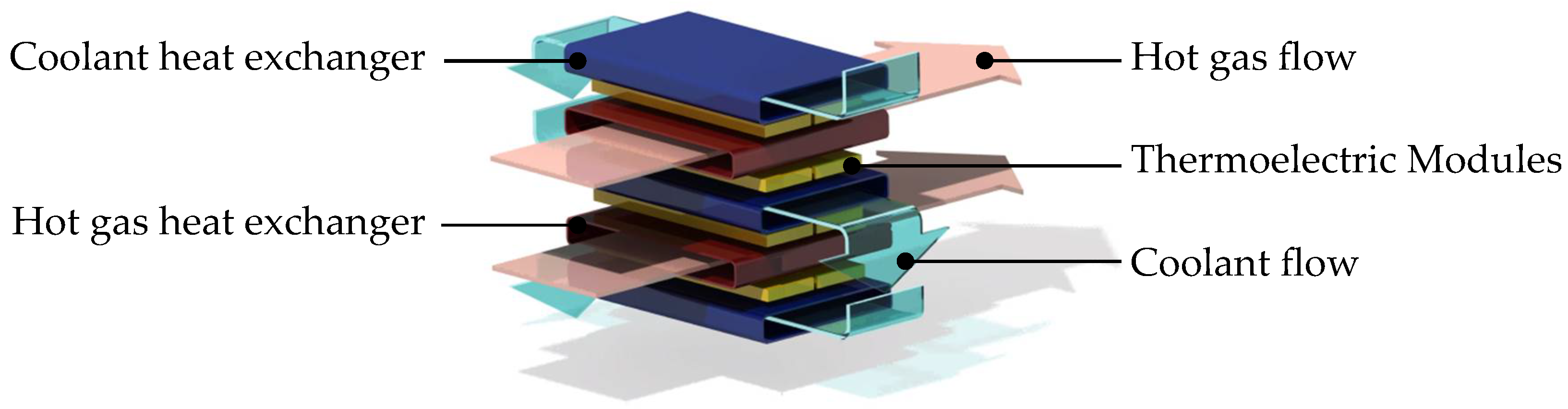
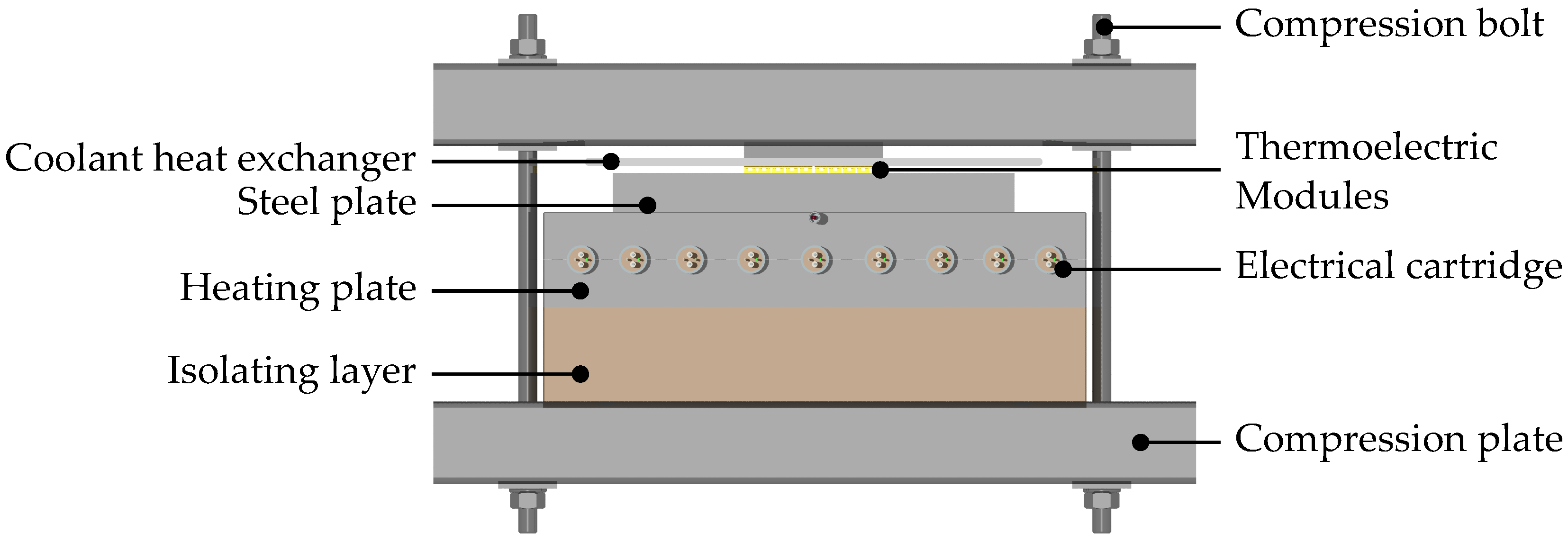
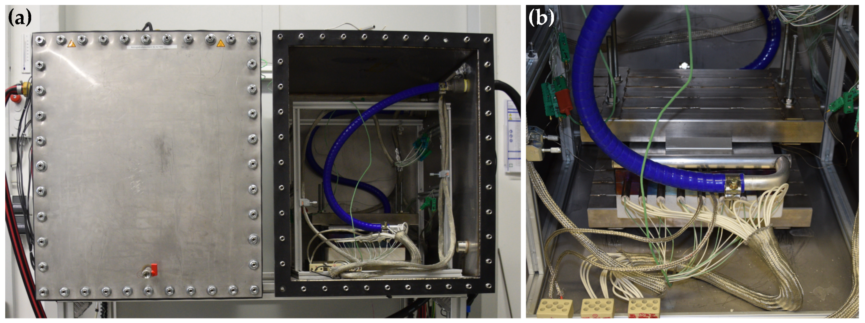
2. Methodology
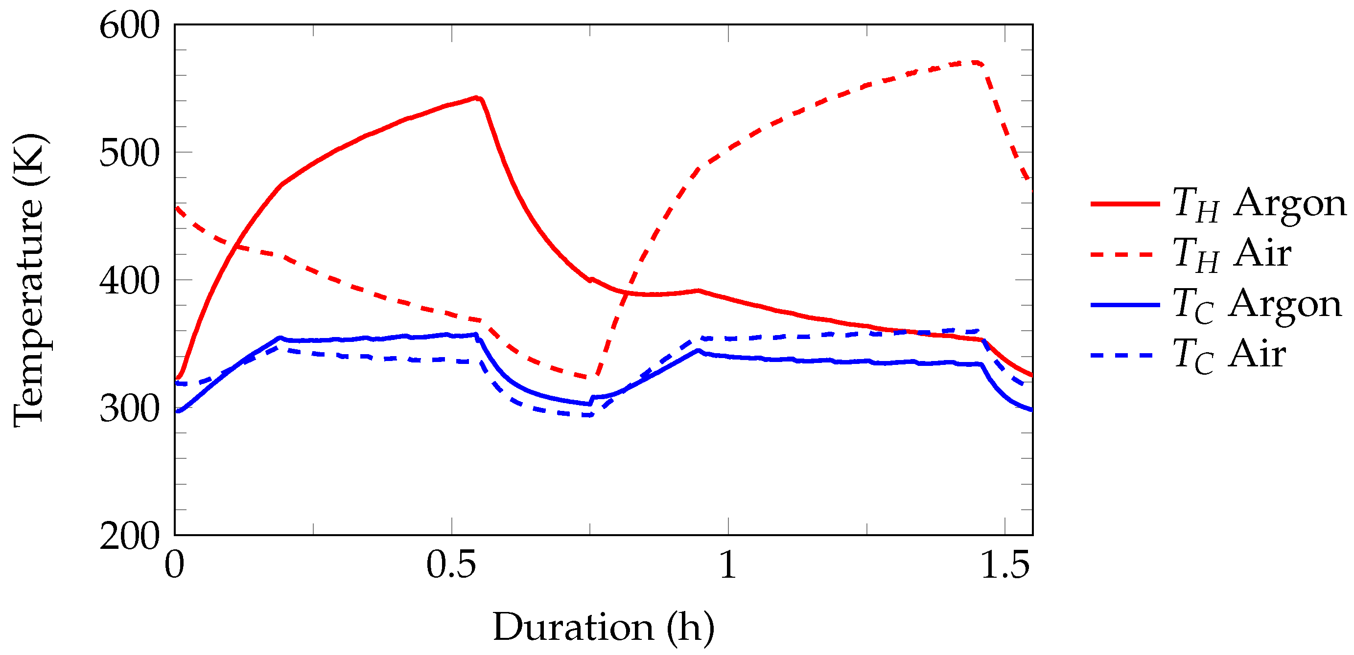
3. Results and Discussion
4. Conclusions
Author Contributions
Funding
Data Availability Statement
Acknowledgments
Conflicts of Interest
Abbreviations
| BiTe | Bismuth telluride |
| C | Cold side |
| H | Hot side |
| MPPT | Maximum power point tracker |
| PbTe | Lead telluride |
| TEG | Thermoelectric Generator |
| TEM | Thermoelectric Module |
References
- Forman, C.; Muritala, I.K.; Pardemann, R.; Meyer, B. Estimating the global waste heat potential. Renew. Sustain. Energy Rev. 2016, 57, 1568–1579. [Google Scholar] [CrossRef]
- Rowe, D.M. (Ed.) Thermoelectrics Handbook: Macro to Nano; CRC/Taylor & Francis: Boca Raton, FL, USA, 2006. [Google Scholar]
- Chen, X.Q.; Fan, S.J.; Han, C.; Wu, T.; Wang, L.J.; Jiang, W.; Dai, W.; Yang, J.P. Multiscale architectures boosting thermoelectric performance of copper sulfide compound. Rare Met. 2021, 40, 2017–2025. [Google Scholar] [CrossRef] [PubMed]
- Kober, M. Holistic Development of Thermoelectric Generators for Automotive Applications. J. Electron. Mater. 2020, 49, 2910–2919. [Google Scholar] [CrossRef]
- Kober, M.; Knobelspies, T.; Rossello, A.; Heber, L. Thermoelectric Generators for Automotive Applications: Holistic Optimization and Validation by a Functional Prototype. J. Electron. Mater. 2020, 49, 2902–2909. [Google Scholar] [CrossRef]
- Heber, L.; Schwab, J. Modelling of a thermoelectric generator for heavy-duty natural gas vehicles: Techno-economic approach and experimental investigation. Appl. Therm. Eng. 2020, 174, 115156. [Google Scholar] [CrossRef]
- Heber, L.; Schwab, J.; Knobelspies, T. 3 kW Thermoelectric Generator for Natural Gas-Powered Heavy-Duty Vehicles—Holistic Development, Optimization and Validation. Energies 2022, 15, 15. [Google Scholar] [CrossRef]
- Schwab, J.; Bernecker, M.; Fischer, S.; Seyed Sadjjadi, B.; Kober, M.; Rinderknecht, F.; Siefkes, T. Exergy Analysis of the Prevailing Residential Heating System and Derivation of Future CO2-Reduction Potential. Energies 2022, 15, 3502. [Google Scholar] [CrossRef]
- Bates, H.E.; Weinstein, M. Sublimation rates In vacuo of PbTe and Pb0.5Sn0.5Te thermoelements. Adv. Energy Convers. 1966, 6, 177–180. [Google Scholar] [CrossRef]
- Ohsugi, I.J.; Tokunaga, D.; Kato, M.; Yoneda, S.; Isoda, Y. Dissociation and sublimation of tellurium from the thermoelectric tellurides. Mater. Res. Innov. 2015, 19, S5-301–S5-303. [Google Scholar] [CrossRef]
- Leszczynski, J.; Wojciechowski, K.T.; Malecki, A.L. Studies on thermal decomposition and oxidation of CoSb3. J. Therm. Anal. Calorim. 2011, 105, 211–222. [Google Scholar] [CrossRef]
- Brož, P.; Zelenka, F.; Kohoutek, Z.; Vřešťál, J.; Vykoukal, V.; Buršík, J.; Zemanová, A.; Rogl, G.; Rogl, P. Study of thermal stability of CoSb3 skutterudite by Knudsen effusion mass spectrometry. Calphad 2019, 65, 1–7. [Google Scholar] [CrossRef]
- Zelenka, F.; Brož, P.; Vřešťál, J.; Buršík, J.; Zemanová, A.; Rogl, G.; Rogl, P. Study of thermal stability of half-Heusler alloys TiFe1.33Sb and TixNb1-xFeSb (x = 0, 0.15) by differential thermal analysis and Knudsen effusion method. Calphad 2021, 74, 102292. [Google Scholar] [CrossRef]
- Berchenko, N.; Fadeev, S.; Savchyn, V.; Kurbanov, K.; Trzyna, M.; Cebulski, J. Pb–Te–O phase equilibrium diagram and the lead telluride thermal oxidation. Thermochim. Acta 2014, 579, 64–69. [Google Scholar] [CrossRef]
- Chen, L.; Goto, T.; Tu, R.; Hirai, T. High-temperature Oxidation Behavior Of PbTe And Oxidation-resistive Glass Coating. In Proceedings of the 16th International Conference on Thermoelectrics (1997), Dresden, Germany, 26–29 August 1997. [Google Scholar]
- Sklad, A.C.; Gaultois, M.W.; Grosvenor, A.P. Examination of CeFe4Sb12 upon exposure to air: Is this material appropriate for use in terrestrial, high-temperature thermoelectric devices? J. Alloys Compd. 2010, 505, L6–L9. [Google Scholar] [CrossRef]
- Xia, X.; Qiu, P.; Shi, X.; Li, X.; Huang, X.; Chen, L. High-Temperature Oxidation Behavior of Filled Skutterudites Yb y Co4Sb12. J. Electron. Mater. 2012, 41, 2225–2231. [Google Scholar] [CrossRef]
- Xia, X.; Qiu, P.; Huang, X.; Wan, S.; Qiu, Y.; Li, X.; Chen, L. Oxidation Behavior of Filled Skutterudite CeFe4Sb12 in Air. J. Electron. Mater. 2014, 43, 1639–1644. [Google Scholar] [CrossRef]
- Skomedal, G.; Kristiansen, N.R.; Engvoll, M.; Middleton, H. Methods for Enhancing the Thermal Durability of High-Temperature Thermoelectric Materials. J. Electron. Mater. 2014, 43, 1946–1951. [Google Scholar] [CrossRef]
- Shin, D.K.; Kim, I.H.; Park, K.H.; Lee, S.; Seo, W.S. Thermal Stability of La0.9Fe3CoSb12 Skutterudite. J. Electron. Mater. 2015, 44, 1858–1863. [Google Scholar] [CrossRef]
- Kang, H.B.; Saparamadu, U.; Nozariasbmarz, A.; Li, W.; Zhu, H.; Poudel, B.; Priya, S. Understanding Oxidation Resistance of Half-Heusler Alloys for in-Air High Temperature Sustainable Thermoelectric Generators. ACS Appl. Mater. Interfaces 2020, 12, 36706–36714. [Google Scholar] [CrossRef]
- Appel, O.; Cohen, S.; Beeri, O.; Shamir, N.; Gelbstein, Y.; Zalkind, S. Surface Oxidation of TiNiSn (Half-Heusler) Alloy by Oxygen and Water Vapor. Materials 2018, 11, 2296. [Google Scholar] [CrossRef]
- Appel, O.; Breuer, G.; Cohen, S.; Beeri, O.; Kyratsi, T.; Gelbstein, Y.; Zalkind, S. The Initial Stage in Oxidation of ZrNiSn (Half Heusler) Alloy by Oxygen. Materials 2019, 12, 1509. [Google Scholar] [CrossRef]
- Zillmann, D.; Waag, A.; Peiner, E.; Feyand, M.H.; Wolyniec, A. Thermoelectric and Structural Properties of Zr-/Hf-Based Half-Heusler Compounds Produced at a Large Scale. J. Electron. Mater. 2018, 47, 1546–1554. [Google Scholar] [CrossRef]
- Li, C.C.; Drymiotis, F.; Liao, L.L.; Hung, H.T.; Ke, J.H.; Liu, C.K.; Kao, C.R.; Snyder, G.J. Interfacial reactions between PbTe-based thermoelectric materials and Cu and Ag bonding materials. J. Mater. Chem. C 2015, 3, 10590–10596. [Google Scholar] [CrossRef]
- Ferreres, X.R.; Aminorroaya Yamini, S.; Nancarrow, M.; Zhang, C. One-step bonding of Ni electrode to n-type PbTe—A step towards fabrication of thermoelectric generators. Mater. Des. 2016, 107, 90–97. [Google Scholar] [CrossRef]
- Feng, H.; Zhang, L.; Zhang, J.; Gou, W.; Zhong, S.; Zhang, G.; Geng, H.; Feng, J. Metallization and Diffusion Bonding of CoSb3-Based Thermoelectric Materials. Materials 2020, 13, 1130. [Google Scholar] [CrossRef]
- Chu, J.; Huang, J.; Liu, R.; Liao, J.; Xia, X.; Zhang, Q.; Wang, C.; Gu, M.; Bai, S.; Shi, X.; et al. Electrode interface optimization advances conversion efficiency and stability of thermoelectric devices. Nat. Commun. 2020, 11, 2723. [Google Scholar] [CrossRef]
- Nozariasbmarz, A.; Saparamadu, U.; Li, W.; Kang, H.B.; Dettor, C.; Zhu, H.; Poudel, B.; Priya, S. High-performance half-Heusler thermoelectric devices through direct bonding technique. J. Power Sources 2021, 493, 229695. [Google Scholar] [CrossRef]
- Al Malki, M.M.; Qiu, Q.; Zhu, T.; Snyder, G.J.; Dunand, D.C. Creep behavior and postcreep thermoelectric performance of the n-type half-Heusler alloy Hf0.3Zr0.7NiSn0.98Sb0.02. Mater. Today Phys. 2019, 9, 100134. [Google Scholar] [CrossRef]
- Ding, L.C.; Akbarzadeh, A.; Date, A. Performance and reliability of commercially available thermoelectric cells for power generation. Appl. Therm. Eng. 2016, 102, 548–556. [Google Scholar] [CrossRef]
- Harish, S.; Sivaprahasam, D.; Jayachandran, B.; Gopalan, R.; Sundararajan, G. Performance of bismuth telluride modules under thermal cycling in an automotive exhaust thermoelectric generator. Energy Convers. Manag. 2021, 232, 113900. [Google Scholar] [CrossRef]
- Riyadi, T.W.B.; Utomo, B.R.; Effendy, M.; Wijayanta, A.T.; Al-Kayiem, H.H. Effect of thermal cycling with various heating rates on the performance of thermoelectric modules. Int. J. Therm. Sci. 2022, 178, 107601. [Google Scholar] [CrossRef]
- Merienne, R.; Lynn, J.; McSweeney, E.; O’Shaughnessy, S.M. Thermal cycling of thermoelectric generators: The effect of heating rate. Appl. Energy 2019, 237, 671–681. [Google Scholar] [CrossRef]
- Barako, M.T.; Park, W.; Marconnet, A.M.; Asheghi, M.; Goodson, K.E. Thermal Cycling, Mechanical Degradation, and the Effective Figure of Merit of a Thermoelectric Module. J. Electron. Mater. 2013, 42, 372–381. [Google Scholar] [CrossRef]
- Salvador, J.R.; Cho, J.Y.; Ye, Z.; Moczygemba, J.E.; Thompson, A.J.; Sharp, J.W.; König, J.D.; Maloney, R.; Thompson, T.; Sakamoto, J.; et al. Thermal to Electrical Energy Conversion of Skutterudite-Based Thermoelectric Modules. J. Electron. Mater. 2013, 42, 1389–1399. [Google Scholar] [CrossRef]
- Siadatan, A.; fakhari, M.; Taheri, B.; Sedaghat, M. New fundamental modulation technique with SHE using shuffled frog leaping algorithm for multilevel inverters. Evol. Syst. 2020, 11, 541–557. [Google Scholar] [CrossRef]
- Torkaman, H.; Fakhari, M.; Karimi, H.; Taheri, B. New Frequency Modulation Strategy with SHE for H-bridge Multilevel Inverters. In Proceedings of the 2018 4th International Conference on Electrical Energy Systems (ICEES), Chennai, India, 7–9 February 2018; pp. 157–161. [Google Scholar] [CrossRef]


Disclaimer/Publisher’s Note: The statements, opinions and data contained in all publications are solely those of the individual author(s) and contributor(s) and not of MDPI and/or the editor(s). MDPI and/or the editor(s) disclaim responsibility for any injury to people or property resulting from any ideas, methods, instructions or products referred to in the content. |
© 2023 by the authors. Licensee MDPI, Basel, Switzerland. This article is an open access article distributed under the terms and conditions of the Creative Commons Attribution (CC BY) license (https://creativecommons.org/licenses/by/4.0/).
Share and Cite
Schwab, J.; Fritscher, C.; Filatov, M.; Kober, M.; Rinderknecht, F.; Siefkes, T. Experimental Analysis of the Long-Term Stability of Thermoelectric Generators under Thermal Cycling in Air and Argon Atmosphere. Energies 2023, 16, 4145. https://doi.org/10.3390/en16104145
Schwab J, Fritscher C, Filatov M, Kober M, Rinderknecht F, Siefkes T. Experimental Analysis of the Long-Term Stability of Thermoelectric Generators under Thermal Cycling in Air and Argon Atmosphere. Energies. 2023; 16(10):4145. https://doi.org/10.3390/en16104145
Chicago/Turabian StyleSchwab, Julian, Christopher Fritscher, Michael Filatov, Martin Kober, Frank Rinderknecht, and Tjark Siefkes. 2023. "Experimental Analysis of the Long-Term Stability of Thermoelectric Generators under Thermal Cycling in Air and Argon Atmosphere" Energies 16, no. 10: 4145. https://doi.org/10.3390/en16104145
APA StyleSchwab, J., Fritscher, C., Filatov, M., Kober, M., Rinderknecht, F., & Siefkes, T. (2023). Experimental Analysis of the Long-Term Stability of Thermoelectric Generators under Thermal Cycling in Air and Argon Atmosphere. Energies, 16(10), 4145. https://doi.org/10.3390/en16104145