1. Introduction
Over the last decade, advancements in Energy Storage Systems (ESS) technology and reductions in the global average Levelized Cost of Electricity (LCOE) for solar and wind energy have resulted in a significant reduction in the payback period of Hybrid Renewable Energy Systems (HRESs), particularly in locations with ample sun and wind resources.
A considerable number of works and review articles related to the energy transition projects for isolated power grids demonstrate that a mixture of multiple energy sources and energy demand types may effectively overcome the obstacles of variability, unpredictability, and randomness of solar/wind energy [
1,
2,
3,
4,
5,
6,
7]. This approach offers a more reliable and robust energy system that can meet the increasing energy demand of the island while reducing its dependency on imported fossil fuels [
8,
9,
10]. However, most of the studies on 100% RES rarely consider sector coupling, as most of them have only focused on the power sector. The aim of this study is to create a comprehensive model that can examine the possibility of increasing renewable energy sources (RES)’ penetration in isolated grids. This model will also consider the decarbonization of providing potable water and the electrification of inland transportation using the V2G concept.
The shift towards 100% renewable energy sources for islanded power systems brings various challenges, such as the high front costs and operational and maintenance expenses of HRES, as well as concerns about energy reliability and environmental impacts [
1,
11]. Additionally, designing an effective HRES involves considering several key factors, such as the site’s geographic characteristics, the capacity factor of the VRES, the cost-effectiveness of ESS, the size of the application, and the level of inland transport electrification. Sizing the system’s components is critical and should be integrated with the energy management strategy to ensure reliable and cost-effective operation of the system. The HRES is a well-designed and comprehensive solution that can help to transform the energy system of Porto Santo Island and pave the way for a more sustainable future.
HRES typically combine solar and wind power and may also include a diesel generator for backup. Each type of HRES has its own advantages and challenges, and the choice of system depends on factors such as location, energy demand, and available resources. HRES can be further classified into three main types based on their connection to the electrical grid and energy storage options. The first type is a system that benefits hydropower or a Pumped Hydro Storage (PHS) system as the main energy storage technology. Islands with PHS, such as El Hierro [
12] may have an advantage in achieving a 100% renewable power system due to the long-term energy storage capability provided by this technology.
The second type of HRES are systems that are connected to another electrical grid via a submarine power cable. The Greek island of Tilos [
13] and Aran in Ireland [
14,
15] are examples of this group. The use of submarine power significantly impacts the assumptions and equations used to achieve a 100% renewable power system as an isolated system. The third type includes isolated systems that do not have access to PHS and may rely on other types of ESSs. The Italian island of Pantelleria [
16] is an example of this type of system. These isolated islands lack a submarine connection and rely heavily on ESS to increase the share of VRES.
ESSs are limited by their cost and storage capacity. For instance, batteries can provide short-term energy storage solutions and can be deployed in a wider range of locations, but they might be cost-ineffective to provide long-term (seasonal) ESS services. As a long-term ESS, Underwater Compressed Air Energy Storage (UW-CAES) systems may be a highly prospective technology particularly for islands and coastal locations, since they can be coupled with offshore wind turbines. UW-CAES is still in the early stages of development, but it has the potential to provide high-density energy storage in a wider range of locations. According to a study conducted by Hunt et al. [
17], the cost of isothermal UW-CAES can range from 2 to 10 USD/kWh of stored electric energy and 1500 to 3000 USD/kW of installed capacity, depending on the system’s size, location, depth of the underwater storage, and operating costs. This cost is higher than that for some other ESSs such as lithium-ion batteries, but it can provide benefits such as a longer lifespan and scalability.
Demand-side management is the other key pillar in the transition towards 100% renewable power systems. Many researchers in the field and real-world examples have demonstrated that coupling RES with reverse-osmosis desalination plants or RODPs is promising in terms of economic and technical feasibility while significantly reducing the carbon footprint associated with potable water provision [
18,
19]. An integrated RODP with RES coupled with an ESS can respond quickly enough and maintain the necessary change for a long enough duration in response to significant changes in the power grid.
To determine the optimal size of a HRES in terms of installed power (in kW/kWh), various studies have used different sizing methodologies that utilize different configurations and mixes of energy sources to increase the renewable energy fraction. These methodologies can be categorized into traditional methods, Artificial Intelligence (AI) methods, hybrid methods, and software-based simulations [
6,
20,
21,
22,
23,
24]. It is important to note that the mathematical models employed in these sizing methodologies have different objective functions, decision variables, and constraints, which makes achieving optimal sizing a challenging task when combining multiple types of energy sources and complementary energy storage systems. The Pareto optimality concept is used to solve and optimize the given solutions by simultaneously considering multiple objectives, such as minimizing ESS capacity, power losses, and expected energy not supplied, while maximizing power supply reliability and minimizing the system lifecycle cost. Pareto optimality is a concept in multi-objective optimization that involves finding the optimal solutions for multiple conflicting objectives. The solutions that cannot be improved in any objective without compromising another objective are said to be Pareto-optimal. In the context of HRES sizing, the Pareto front represents the set of solutions that are optimal with respect to multiple conflicting objectives such as cost, energy efficiency, and environmental impact. By considering solutions that lie on the Pareto front, decision makers can make an informed decision on the most suitable sizing approach based on their specific requirements and preferences [
25,
26]. Thus, Pareto optimality is a key consideration in multi-objective optimization for HRES sizing, and it enables decision makers to find solutions that achieve a balance between multiple competing objectives.
Commonly used evaluation indicators for capacity optimization include reliability, as well as economic, environmental, and social indicators. Excessive capacity can increase the payback period of the system’s investments, whereas insufficient capacity can compromise power supply reliability. Many studies have used cost–benefit analysis to balance capital investment, system reliability, and environmental impacts. For large-scale grid-connected hybrid systems with hydro, Zhang et al. [
27] presented an optimization method to determine the capacity of a PV power plant integrated into existing hydropower stations.
Incorporating the water provision and inland transportation sectors in an energy transition plan increases complexity and uncertainty. The electrification of transportation with the presence of considerable solar PV panels may lead to a steep duck curve due to uncontrolled charging but can also provide flexible ramping through smart charging programs. A duck curve refers to the shape of the net load curve on power grids that have a high penetration of solar power generation. It is called a “duck curve” because the curve resembles the shape of a duck’s belly. The curve shows a steep drop in net load during the day as solar power production increases and a steep rise in net load in the evening as solar power production decreases and demand for electricity increases. This can create challenges for grid operators who must balance the electricity supply and demand in real time to maintain the stability of the grid. To address this issue, grid operators may need to curtail renewable energy production, increase energy storage capacity, or add flexible resources that can quickly adjust to changes in demand. Implementing a deliberate charging and discharging strategy for Electric Vehicles (EVs) can be an effective way to tackle the aforementioned problems and advance decarbonization, improve energy efficiency and air quality, and promote the integration of various energy sectors, albeit at the cost of increasing the island’s electricity demand.
This study aimed to investigate the energy transition of Porto Santo Island towards a 100% renewable energy system for power generation, inland transport, and potable water provision, considering various fossil-fuel-consuming sectors such as transport and a potable water supply system. The study used a multi-objective optimization assessment to assess the energy transition of the island, using a modified NSGA-II algorithm. This work is organized as follows:
Section 2 presents the demand profiles of the selected site, discusses the available resources, and proposes the system design.
Section 3 is dedicated to the optimization model that iterates the simulation model, allowing for an optimal combination and size of the components of a HRES.
Section 5 discusses the obtained results as well as facts revealed through the current study and sheds light on future works.
2. System Design
Porto Santo island, with its 5483 inhabitants and an area of 42.17 km
2 (2011), is the northern- and easternmost island of Madeira’s archipelago, located in the Atlantic Ocean, west of Europe and Africa. The Portuguese island has been practicing developments that will allow the territory to become a touristic destination under international standard recognition, being free from fossil fuel sources and with nearly zero pollutant emissions. The initiative started in 2012 with the launch of the Sustainable Energy Action Plan of Porto Santo Island, developed under the Pact of Islands’ advisory [
28]. In 2016, the local executive branches took the project to a new phase by launching the Smart Fossil Free Island project. They aimed to enable the gradual replacement of fossil fuel resources with RES in the medium and long term [
29].
Indeed, the implementation of a HRES in Porto Santo can bring various benefits such as reducing the island’s dependence on imported fossil fuels as well as its carbon footprint. The integration of V2G technology can also contribute to the stability and reliability of the grid while reducing carbon emissions from the transportation sector. The optimization of the HRES capacity can ensure efficient use of the available renewable resources, energy storage, and demand management, leading to a more cost-effective and sustainable energy system. Overall, the proposed HRES can provide a valuable solution for Porto Santo’s energy needs and serve as a model for other isolated grids facing similar challenges.
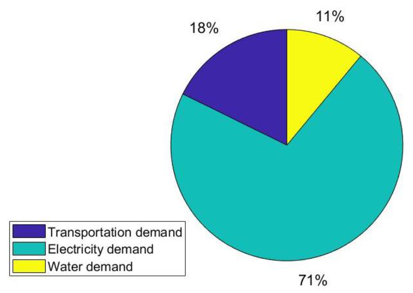
Figure 1 shows the share of the demand for each sector for one year.
Seawater desalination in Porto Santo is the only solution to supply potable water for public use. The annual water provision on the island accounts for 11% to 15% of the total electricity demand, as reverse-osmosis desalination plants (RODPs) solely consume electricity for desalinating seawater. Additionally, if all Combustion Engine Vehicles (CEV) were to be replaced with Electric Vehicles (EV), the total electricity demand would increase by 18%. This information highlights the significant impact that water desalination and transportation have on the electricity demand on the island. Therefore, implementing renewable energy sources and energy-efficient technologies, such as EVs and V2G, can help reduce the reliance on imported fossil fuels and increase the island’s energy independence. However, the increase in electricity demand due to EVs should be carefully considered in the sizing and optimization of the HRES components to ensure the stability and reliability of the grid.
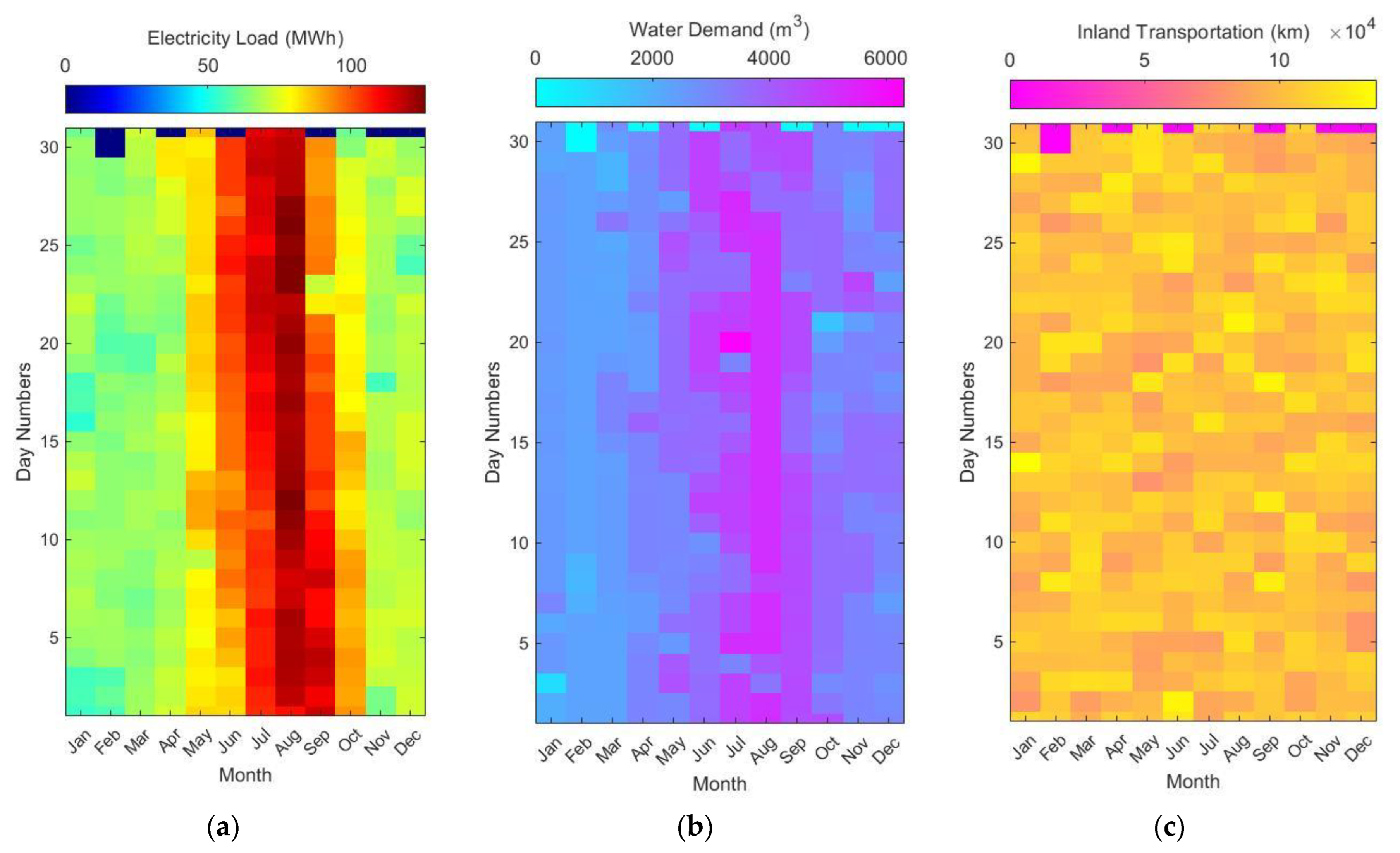
As with many other islands, the island’s water and energy demands are influenced by the variability and structure of its tourism industry [
30].
Figure 2 shows that the electricity and water demands nearly doubled during the high seasons (June, July, August, and September), requiring a high reserve capacity. The electricity demand may reach 130 MWh per day.
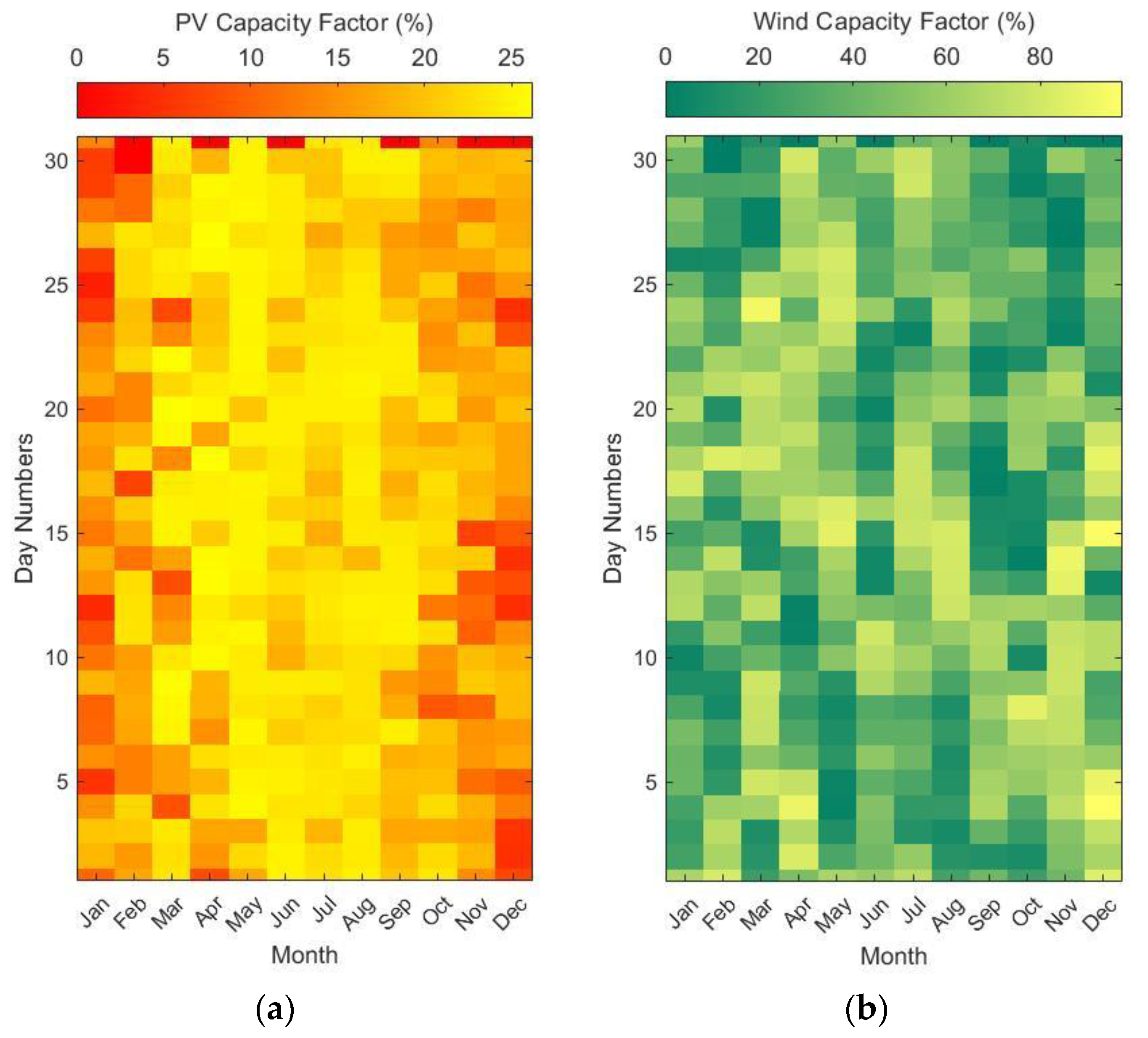
Figure 3 presents the capacity factor for solar power and wind power in terms of the daily average. The solar production, with an annual mean of 19% for its capacity factor, varies throughout the course of a year, representing a higher value from mid-April until the end of September. Wind power, with an annual average of 43% for its capacity factor, though, does not follow a particular pattern. The inland travel pattern and the Electric Vehicles (EVs)’ connectivity to the grid are modeled using probability distributions, adopted from the works conducted by Donati et al. [
31] and Brady and O’Mahony [
32].
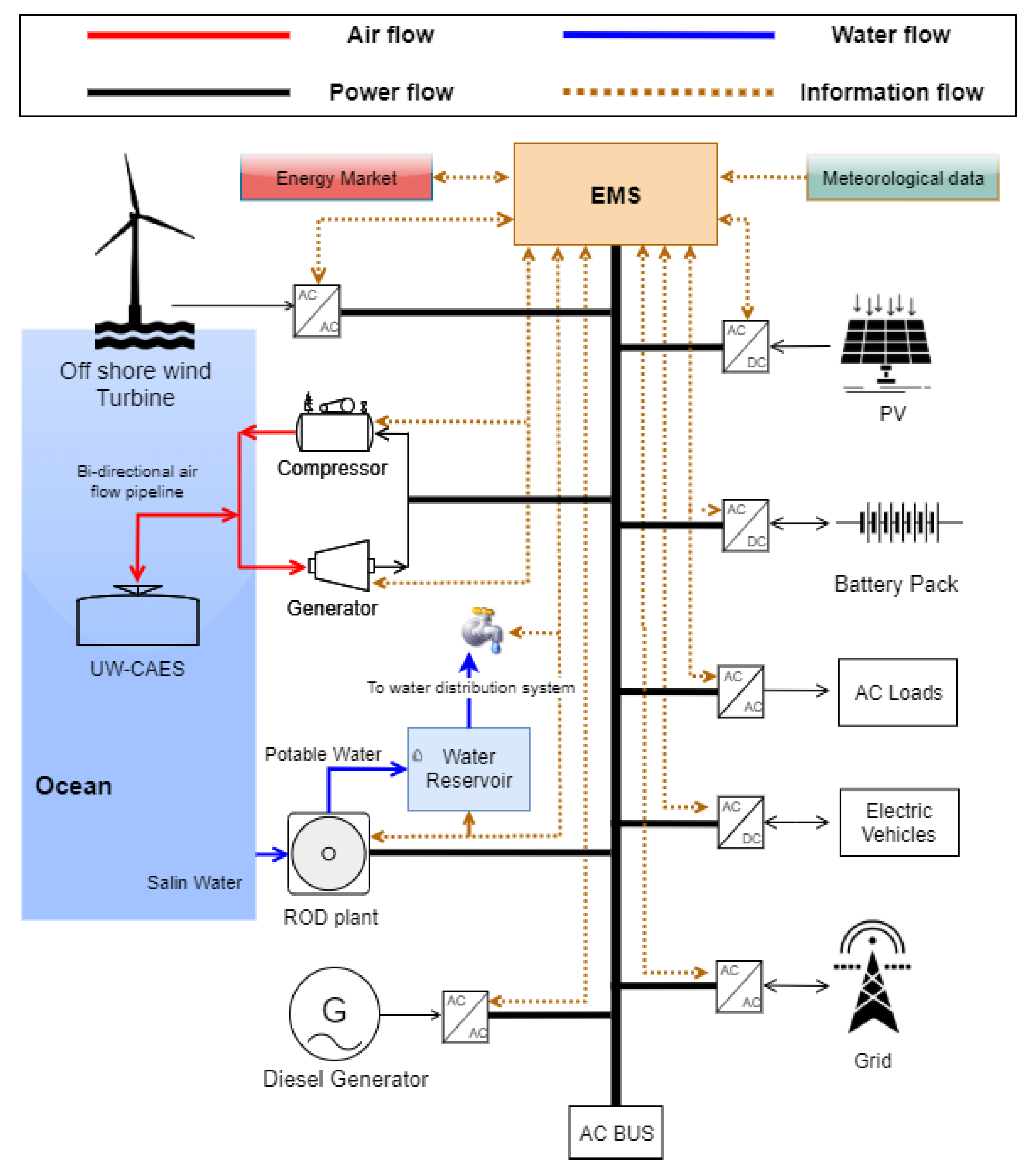
The HRES proposed in this study, as shown in
Figure 4, is a complex system that integrates VRES and ESS technologies, a transport fleet, and a water provision system to provide reliable and sustainable power to Porto Santo Island. The combination of offshore wind turbines and PV arrays allows for a diverse energy mix that can help to optimize energy production throughout the year.
The Energy Management System (EMS) serves as a central hub that integrates all relevant data and devises a plan for system operation in advance. The water reservoir can also be used to store excess energy during periods of high RES production, thereby providing additional flexibility to the system. The existing diesel generator (DG) is retained in the system as a backup power source in case of emergencies or when the RES output is insufficient to meet demand. In 2019, a Li-ion battery pack with a usable capacity of 4 MW/3 MWh was installed to enhance the system’s electro-productivity [
29]. The battery pack’s capacity and power were upgraded to 12 MWh and 6 MW, respectively, in 2022. Through a Vehicle-to-Grid (V2G) program, the ESS devices, UW-CAES, battery packs, and EVs might be used to provide spinning reserve and load-following capabilities and to balance out variations in energy production and consumption. Special attention should be given to reserves, as the increased uncertainty associated with RES production requires higher reserve values.
In UW-CAES, compressed air is usually stored in submerged expandable air accumulators, which are placed at the bed of the ocean using the hydrostatic pressure resulting from the water column [
35]. Various design parameters, such as the pipe diameter, expander and compressor efficiencies, and air storage depth, may affect the overall system performance, and thus its economic feasibility. For instance, the greater the depth of the ocean, the lower the cost of the project may be. Hunt et al. [
36] estimated that the cost of isothermal UW-CAES systems vary from 1 to 10 USD/kWh of stored electric energy and 1500 to 3000 USD/kW of installed capacity. They showed that this could be a feasible option to complement batteries, providing long-term energy storage cycles. Tiano and Rizzo [
37] studied the application of UW-CAES for fully powering the Sicily region (Italy) with VRES (wind and solar power). They showed that the depth of the sea where the UW-CAES system is placed and its distance from the coast considerably affect the overall installation cost, as the available energy density in kWh/m
3 of the vessel increases by depth, and the distance from the cost increases the cost of the cables. However, the offshore wind farm’s placement close to a complementary UW-CAES may reduce the total system cost. In comparison with PHS and batteries, a UW-CAES system has a substantially lower environmental footprint. It does not require flooding an area to create a reservoir, nor does it require a large volume of mined resources [
36].
Designing an effective HRES involves considering several key factors, such as the site’s geographic characteristics, the capacity factor of the VRES, the cost-effectiveness of the ESS, the size of the application, and the level of inland transport electrification.
Table 1 presents the parameters used in this study for economic and environmental analyses.
It is considered that all EVs are from the same type with a battery capacity of 52 kWh, which are able to participate in a V2G program through a bi-directional interface with a constant charging/discharging power of 3.7 kW.
3. Materials and Methods
The use of a heuristic algorithm such as NSGA-II allows for a more flexible and efficient approach to solving the multi-objective optimization problem for the HRES on Porto Santo Island. Heuristic algorithms are advantageous for modeling and solving complex problems, but they may also have limitations, such as the possibility of falling into local optimal solutions. However, the NSGA-II algorithm has been shown to perform well in previous studies and can provide a set of non-dominated solutions that can be used to evaluate the trade-offs between different objectives [
6,
44]. The framework developed in this study aims to assess the feasibility and cost-effectiveness of different energy transition pathways for the island, taking into account the energy, economic, and environmental factors of the HRES configuration.
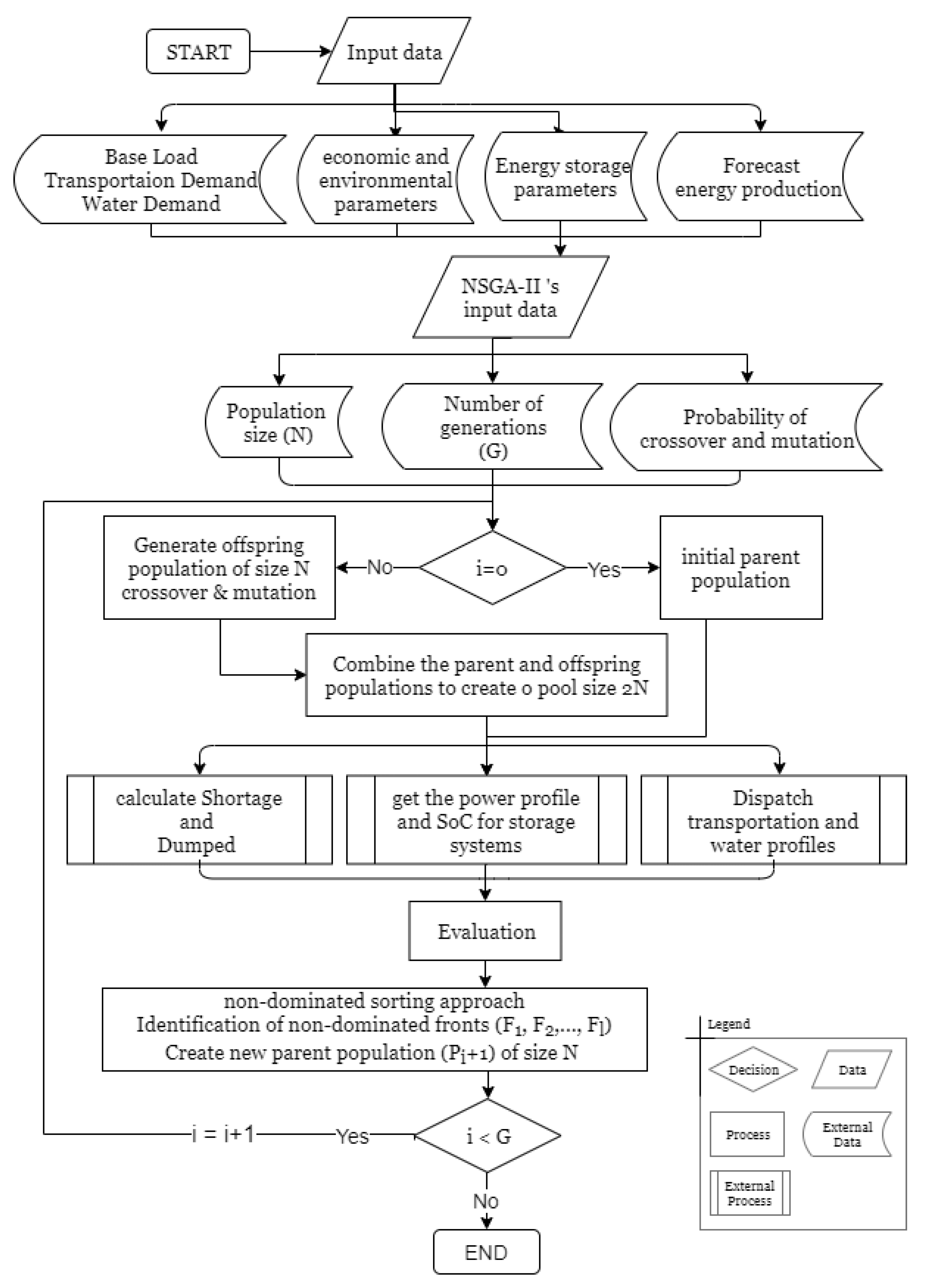
Figure 5 demonstrates a flowchart of the modified NSGA-II and system simulation block (the implementation is flexible to add or remove technologies).
The NSGA-II algorithm provides a set of solutions or individuals with different values of decision variables (). The algorithm starts with reading the information. This includes the demand profiles of electricity, potable water, and inland transportation; forecasts of energy production by solar PV panels and wind turbines; economic and environmental parameters; and energy storage parameters. The NSGA-II algorithm is configured with specific parameters, including a population size (N) of 50, 400 generations (G) and probabilities for the crossover (0.7) and mutation (0.4) operators to run the optimization process. The optimization process starts with the generation of an initial parent population. These solutions are then passed on to the simulation block. Each individual submits to an external process, where one year of operation is simulated. The output is evaluated based on the three performance criteria: minimizing LPSP, minimizing COE, and maximizing avoided CO2.
Each solution represents a particular combination of installed capacities of PV panels and wind turbines, the number of EVs, the power and capacity of UW-CAES (kW/kWh), the size of the water tank, and the operation plan for the RODP.
Table 2 provides the ranges of decision variables (inputs) that are used for system optimization.
The table above shows the installed power capacity range of PV panels and wind turbines, which varies from 0 to 10 MWp and 0 to 16 MWp, respectively. The inclusion of zero allows for exploring potential solutions that solely utilize one type of VRES. For the UW-CAES system, two variables were defined: represents the charging/discharging power (MW), and denotes the storage capacity (MWh). means no UW-CAES is considered in the HRES. Variable represents the number of EVs, which ranges from 0 to 3000 vehicles, where zero indicates no transport electrification, and 3000 represents complete transport electrification on the island. Variable is assigned a range of 10,000 to 20,000, as the island has a water reservoir with a volume of 10,000 m3. The RODP’s operation plan is split into two decision variables: , which indicates the RODP’s state (0 → off and 1 → on) at time interval , and represents the desalination plant’s power operation at time . All decision variables can only take an integer value that falls within their defined ranges.
3.1. Simulation
The simulation block uses the measured data at an hourly time step of solar and wind power gathered from Ninja (
https://www.renewables.ninja/ accessed on 2 February 2023) and accumulated demands from various sectors (i.e., the island’s base load, transport, and potable water provision). Apart from this, the RODP’s operation plan and V2G are considered as a controllable load. Therefore, the RODP’s operation and the V2G’s operation plans for a one-year simulation period are given. The inland travel pattern and the Electric Vehicles (EVs)’ connectivity to the grid are modeled using probability distributions. Then, the one-year simulation is run to provide the
as follows:
where
denotes the net demand. Accordingly, the shortage and dumped load can be defined:
3.2. Optimization Objectives
Loss of power supply probability (LPSP): This criterion is used to evaluate the power supply reliability. The LPSP value is a number between 0% and 100%, and a smaller value is better. A 0 value means the load can be always met, and a value of 1 denotes the load is never met. Since the mismatch power never exists in charge mode, the
LPSP can be calculated by:
Cost of energy (
COE): This criterion is widely used as an objective function for the economic assessment of a renewable power supply system. It compromises the initial cost of the components and operation and maintenance cost of the proposed solution. It can be calculated as:
CRF is the capital recovery factor that can be obtained from:
where
is the system lifespan, and
stands for the discount rate.
denotes the net present cost of the system, and it may be derived as follows:
where
and
are the cost and the number/capacity of components, respectively. The total cost of any component includes the investment cost (
IC), the operation and maintenance cost (
OMC), and the replacement cost (
RC). Therefore, the
th component’s cost is given by:
In this study, the replacement cost is the estimated cost of the
th component at the end of the component’s lifespan, adopted from studies conducted by Zhao et al. [
45].
is the annual
OMC of the
th component; thus, the
of each component can be obtained from:
where
Y is the system lifespan, and
r denotes the discount rate (
r = 0.06).
Avoided carbon dioxide emissions (
ACO2): Carbon dioxide (CO
2) emissions are an important indicator of the environmental aspect for any power system. In this study, the
ACO2 criterion is designed to measure the CO
2 that might be avoided through the proposed HRES in comparison with the current power sector and transport system. It is denoted in percentage, representing the avoided CO
2 proportion of the proposed solution in comparison with the current condition of the island; thus, a higher value of
ACO2 is better. This aspect is derived from:
where
in kgCO
2 equivalent is the summation of the annual CO
2 emitted by the DG and the CEVs in a scenario in which there are no VRES or EVs employed. Moreover,
compromises the annual CO
2 emissions to operate the system, and
includes the emissions related to the introduction and replacement of the components of the proposed HRES. It is important to note that the accuracy of the ACO
2 calculation relies on obtaining accurate data for the annual CO
2 emissions and the emissions related to introducing and replacing the HRES components.
,
, and
can be derived through Equations (9)–(11):
where
,
, and
in kgCO
2 eq per kWh are the specific CO
2 emissions of the DG, PV panels, and wind turbines that are adopted from the authors’ previous study on the life-cycle assessment and environmental impacts of electricity production in Porto Santo [
46].
denotes the number of EVs that are replaced with CEV, and
is the manufacturing-related CO
2 emissions for each EV.
is the number of conventional vehicles,
denotes the average travel distance in kilometers for each vehicle (i.e., 12,500 km), and
is the CEV’s specific CO
2 emission equivalent per kilometer. In this study, the existing thermal power plant (DG) and combustion engine vehicles (CEV) account for the major sources of CO
2 emissions from the power sector and transportation, and they can be estimated as follows:
where
(kWh/m
3) is the specific consumption (i.e., electricity) for the RODP to desalinate one cubic potable water. It is assumed that there are 3000 vehicles on the island.
Dump load ratio (
DUMP): This criterion is applied to assess the excess energy generated from the VRES. The
DUMP is also a value between 0 and 1. This aspect of excess energy is curtailed when the HRES is in charge mode and cannot store the VRES, meaning all the demands are met, and the ES are full. It can be retained as follows:
To evaluate the economic performance of the solutions over a period of 25 years, two methods are utilized: the profitability index (PI) and the discounted payback period (DPP). The PI is a measure of the profitability of an investment and indicates whether the investment will create value for the investor. The DPP calculates the time required to recover the initial investment, taking into account the time value of money. Both methods provide valuable insights into the long-term economic viability of the proposed solutions. Equations (14) and (15) describe them in mathematical form. For the calculation of the PI, first, the net present value (
NPV) must be calculated. This is the net value of the cash flows of the system, considering the system’s discount from the beginning of the investment. It can be obtained as follows:
where
is the total investment cost at the beginning of the project,
is the lifetime of the project,
is the revenue,
is the annual operation and maintenance cost,
is the replacement cost, and
is the discount rate (0.06). Therefore, the PI can be achieved:
A
PI greater than 1 indicates that the investment is expected to generate a positive value, whereas a
PI less than 1 indicates that the investment is not expected to generate a positive value. The formula for calculating the discounted payback period (
DPP) is:
where
is the number of years before the investment is recovered,
denotes the remaining cost to recover, and
is the cash inflow during the next year. The remaining cost to recover is the difference between the initial investment and the cumulative cash inflows up to that point, and the cash inflow during the next year is the expected cash flow in the following year, discounted to the present value. The discounted cash flows are calculated using a discount rate, which represents the cost of capital or the opportunity cost of investing in an alternative project with similar risks.
4. Results
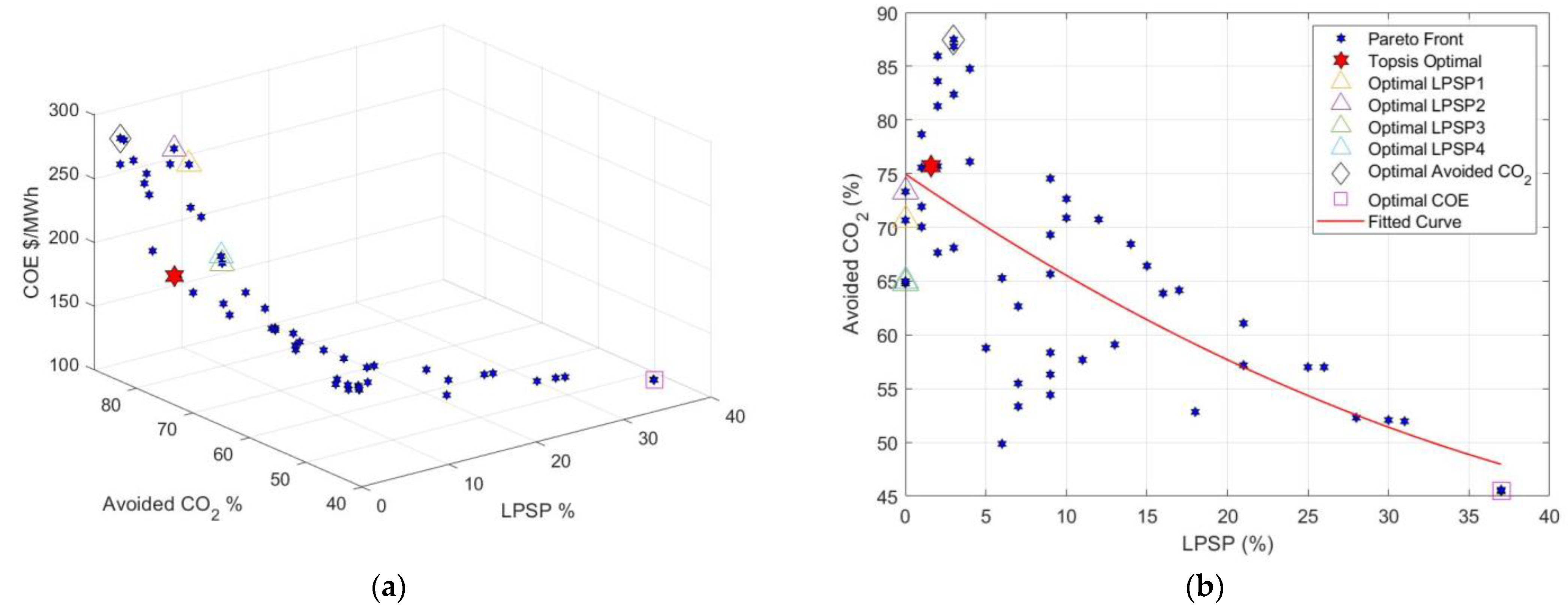
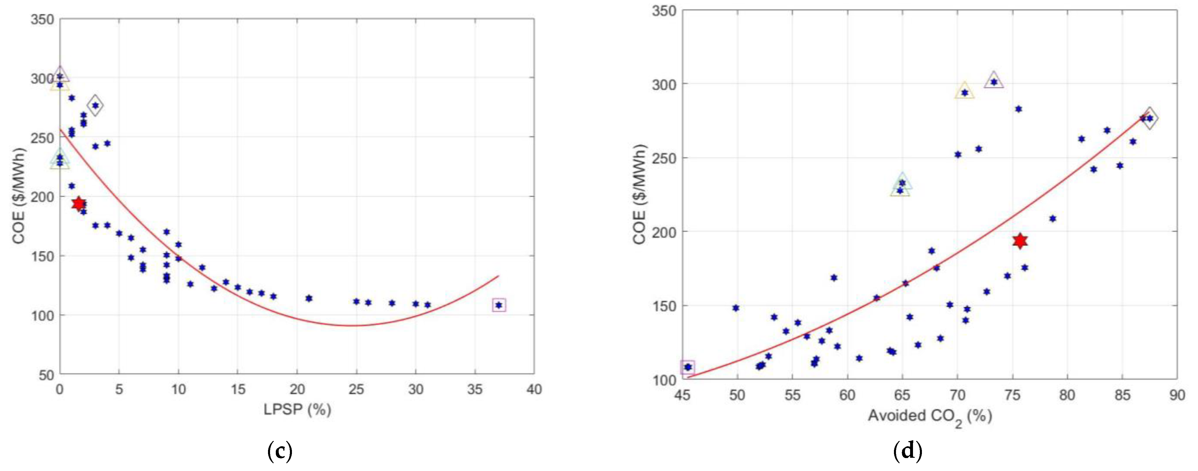
The Pareto front, consisting of fifty solutions, was obtained based on three objectives. They are all feasible solutions to design a HRES. As seen in
Figure 6a, the Pareto front is a three-dimensional space surface, indicating a compromised proposal among the optimal objectives.
Figure 6b–d gives the corresponding mapping plots of the indicators of the three objective functions. It can be found that the COE and avoided CO
2 would increase with LPSP’s reduction.
The triangles in the graphs represent solutions in which the LPSP equals zero, indicating that the total demand is fully met by solar and wind RES. Each triangle corresponds to different values of COE and avoided CO
2 emissions, and no one of these is considered more favorable than the others. The red star in the graph indicates the solution chosen by the TOPSIS (technique for order of preference by similarity to ideal solution) method. It is important to note that the TOPSIS method assumes equal weights for the criteria and normalized the values, since the criteria have incongruous dimensions in this multi-criteria problem. The TOPSIS method was utilized to identify the suboptimal solution from the set of Pareto front solutions. The TOPSIS method is known for its ability to handle both quantitative and qualitative criteria, making it a simple yet effective tool. This method is commonly used in multi-criteria decision making (MCDM) to determine the best alternative among a set of alternatives based on a set of evaluation criteria. However, like any other method, TOPSIS has certain limitations, which include: (i) sensitivity to the normalization process; (ii) dependence on the criteria weights; and (iii) an inability to handle uncertainty and imprecision. Despite these limitations, TOPSIS is still a popular MCDM method and can be useful in many decision-making situations when used appropriately. The square in the graph represents the solution with the lowest COE, but it has the least favorable values for avoided CO
2 and LPSP. The solution highlighted in rhombus presents the highest avoided CO
2 among all the other solutions.
Table 3 lists the system configurations for the marked solutions in
Figure 6.
The highest avoided CO2 emissions achieved is 87%. This solution involves keeping the DG in the system and replacing all CEVs with EVs. Although this solution has a relatively high TIC due to the high front cost of EVs, it performs better in terms of PI, with a 20-year DPP, compared to all the other solutions for optimal LPSP. This suggests that simply increasing the number of installed wind turbines or PV panels may not be the most effective way to reduce emissions. Interestingly, the optimal COE solution does not involve the use of EVs, UW-CAES, or PV panels. It involves installing 6 MW of wind turbines and is able to reduce the CO2 emissions of the system by up to 45%. Additionally, the initial investment pays off within 8 years, and the profit is doubled within the lifespan of the system. The analysis yielded four solutions that achieve the minimum LPSP, each proposing different system configurations to make the island completely free from fossil fuels. However, the TOPSIS optimal solution, which does not consider transport electrification, stands out by achieving 75% avoided CO2 emissions, making it a better choice from an environmental standpoint. Moreover, this solution has a lower COE than all the optimal LPSP and optimal avoided CO2 solutions.
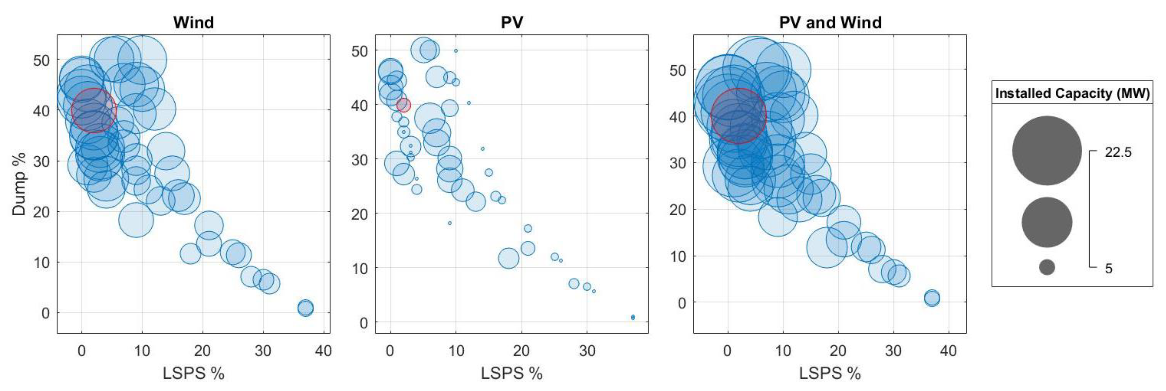
Figure 7 demonstrates the trend of all the solutions in terms of the installed capacity of the wind turbines and the PV panels (separately and accumulated) versus the LPSP and the curtailed power (dumped energy). The red circles present the position of the optimal TOPSIS solution among all the other solutions for wind, PV, and accumulated wind and PV.
As per the analysis, it is evident that in most of the solutions considered, offshore wind turbines have a greater installed capacity than PV panels. This is due to the high capacity factor that wind turbines can achieve in Porto Santo, resulting in better economic performance and a lower dump load ratio. The behavior of the criteria can be visualized in
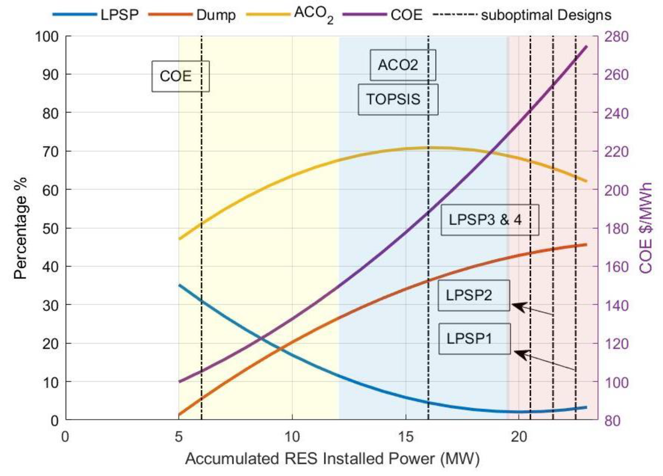
Figure 8, in which each criterion is represented by a fitted curve illustrating how it changes with the increase in installed RES power across all fifty solutions in the Pareto front.
The solid lines in different colors represent the fitted curves for each criterion, and the dashed lines indicate the position of each suboptimal solution in terms of the accumulated installed power of renewable energy sources. The graph is divided into three colored areas: yellow, blue, and red, representing different subcategories of solutions. The red area, in which LPSP 1, 2, 3, and 4 fall, indicates that the isolated system of Porto Santo requires at least 20 MW of accumulated RES installed power (wind and PV panels) to become fully independent of fossil fuels. However, it should be noted that the graph only displays the accumulated RES and not the other system components. The LPSP reaches its minimum in the red zone, and the COE curve shows a steep incline. Nevertheless, the increase in RES and the elimination of fossil fuels does not necessarily reduce the CO
2 emissions of the entire system, as evidenced by the downslope of the ACO
2 curve in the red zone. Further analysis of the solutions found on the Pareto front is presented in
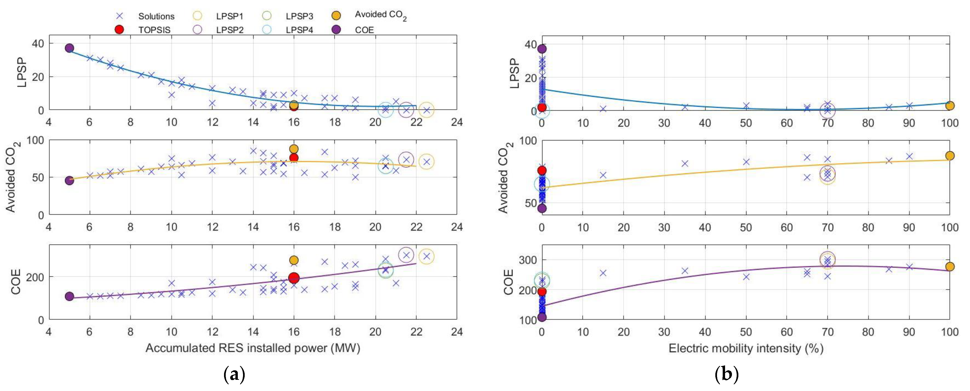
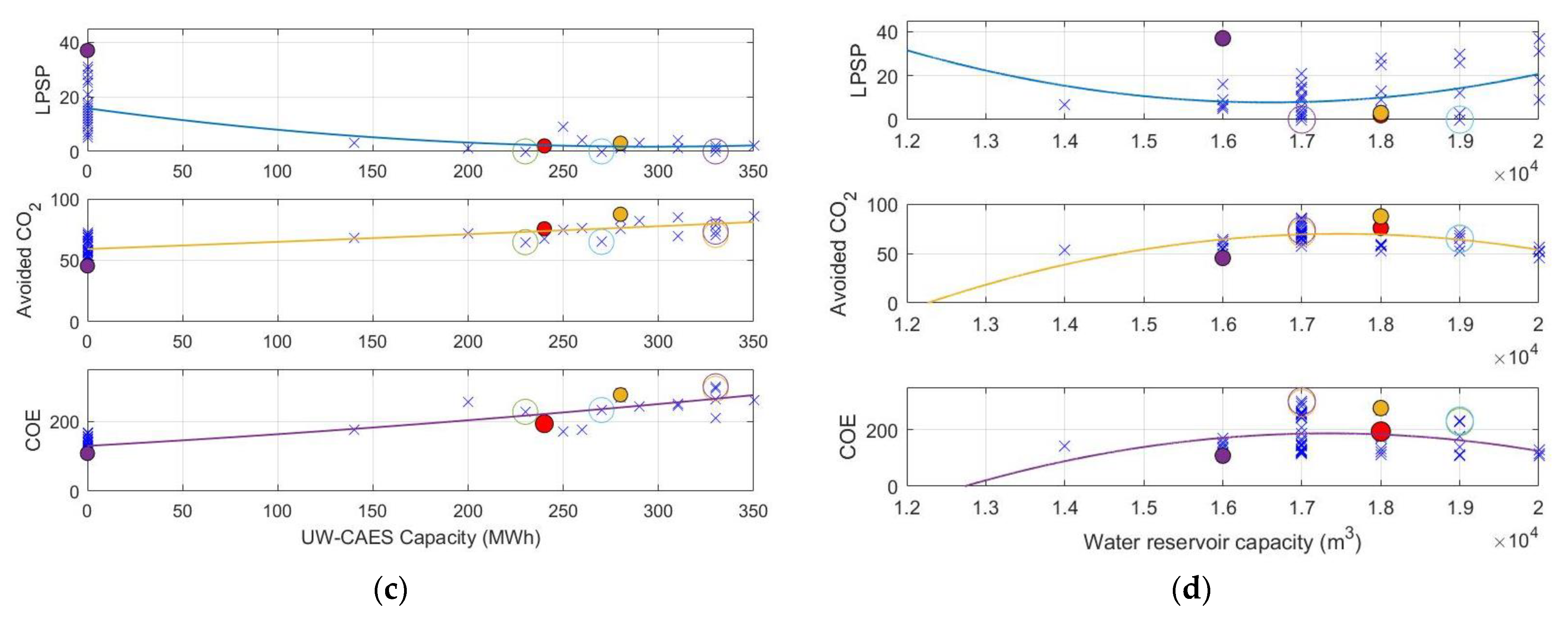
Figure 9.
The figure above is divided in four panels, each presenting the variations in the objectives in terms of increasing the size or the number of the components of the system. A minimum installed capacity of 140 MWh is required for UW-CAES to be effective. Additionally, the optimal solution identified by TOPSIS suggests a capacity of 240 MWh for UW-CAES, with 16 MW installed capacity of renewable energy sources (wind and solar) and no use of electric vehicles. Moreover, the solution includes an increase of 180% in the potable water reservoir capacity. This increase in the water reservoir capacity has a positive impact on the overall performance of the energy system for all the solutions identified. Overall, these findings suggest that the utilization of UW-CAES in combination with renewable energy sources can be an effective solution for energy storage and supply, particularly in areas where potable water is scarce.
The utilization of HRES has become increasingly popular for remote and rural electrification due to the decreasing cost of PV and wind generators in recent years. Consequently, a vast amount of research has focused on developing methods for optimal HRES sizing. However, to the authors’ knowledge, the avoided CO2 emissions criterion has rarely been utilized in other works. The literature shows a significantly higher proportion of research focusing on reliability and economic indicators, with little attention given to environmental and social indicators. Additionally, the sector-coupling strategy has seldom been proposed to facilitate the introduction of variable renewable energy sources (VRES). Therefore, the results of this study may provide valuable insights in this context.
5. Conclusions
This work provides a clear overview of the study’s objectives, methodology, and key findings, including the importance of integrating VRES in islands’ energy systems to reduce their dependency on fossil fuels. Solar and wind energies were considered as the primary resources of energy for an isolated system. Triangled sector-coupling strategies are proposed to meet the electricity, potable water, and transportation demands, with the required load of the RODP and the bi-directional loads associated with EVs under the V2G/G2V approach serving as sources of flexibility.
The use of energy storage technologies has been investigated, and a multi-objective optimization approach was employed to evaluate the energy transition for Porto Santo Island. Energy shifting is facilitated by two storage systems: a lithium-ion battery pack with a capacity of 12 MWh and a maximum power of 6 MW and an UW-CAES system with varying capacities depending on the needs of decision maker.
A RODP coupled with a water reservoir was considered the sole provider of potable water. The UW-CAES system, which serves as a long-term ESS, is cost-effective, with a minimum capacity of 240 MWh and a maximum power of 7 MW. Increasing the potable water reservoir by 50% is beneficial, allowing the RODP to desalinate seawater when the storage systems are full.
The results indicate that full inland transport electrification (introducing 3000 EVs) can account for 18% of the avoided CO2 emissions of the island and shares 28% of the upfront cost of the system.
The UW-CAES would account for 35% to 60% of the system’s costs. An accumulated 5MW installed capacity of offshore wind turbines, with almost zero dumped load, leads to 45% of the costs, cutting CO2 with least COE 108 USD/MWh. However, the thermal power plant must run more than 250 days a year to ensure the security of the supply.
The avoided CO2 optimal solution presents a system with the highest The highest avoided emissions (CO2-equivalent emissions) among the others, whereas it increases the COE dramatically. One interesting finding from the optimization process is that the solution with the highest avoided CO2 emissions involves keeping a diesel generator for supplying 4% of the island’s total demand and using an UW-CAES with a capacity of 280 MWh. This suggests that adding more installed wind turbines or PV panels may not necessarily contribute to reducing the emissions of the entire system.
Determining the optimal or sub-optimal capacity for a HRES is a challenging task that involves addressing several factors. One crucial factor is the accuracy of the load profiles used as input data for allocating the hybrid system. The optimization process results are highly sensitive to the characteristics of solar irradiation and wind speed, making it imperative to obtain accurate input data. Furthermore, the accuracy of the results is also affected by the simulation time step used. Shorter time steps can potentially result in more precise optimal solutions. Limitations of this research include the fact that the study is based on a single case study of Porto Santo Island, and therefore, the findings may not be fully generalizable to other island contexts. The accuracy of the results is also dependent on the input data used, and thus, further efforts should be made to obtain more precise data. Additionally, the economic viability of the proposed energy systems needs to be further evaluated and compared to traditional fossil-fuel-based systems to ensure their long-term sustainability.
The presented results hold the potential to offer valuable insights for stakeholders, policymakers, and island communities in making informed decisions towards a future with sustainable and resilient energy. For instance, policymakers can formulate specific subsidies for the purchase of EVs on the island. Additionally, exploring the ideal offshore wind location in terms of depth and distance from the coast is suggested, especially if this is coupled with UW-CAES. In order to improve the overall system efficiency, increasing the interaction between the water supply system and the energy supply system is suggested. Overall, the study highlights the importance of a holistic approach when designing a HRES for islands, considering the interdependence of different sectors and the role of energy storage technologies. It also emphasizes the need to balance the economics, environmental aspects, and security of the energy transition process. Unlike most previous studies that have mainly focused on the power sector, this study also considers the decarbonization of potable water provision and the electrification of inland transportation using the V2G concept. The use of multi-objective optimization assessment using a modified NSGA-II algorithm to determine the best energy transition strategy for Porto Santo Island is a novel aspect of this work. Therefore, the presented work offers a comprehensive and novel solution to the challenges of achieving a 100% renewable power system on isolated islands while reducing their dependency on imported fossil fuels.
Future works in this area could involve further exploration and optimization of the proposed triangled sector-coupling strategies, especially with regards to their scalability and adaptability to different island contexts. Additionally, research could be conducted to investigate the feasibility of incorporating other renewable energy sources, such as wave or tidal energy, into the proposed energy systems. The potential long-term socio-economic impacts of the proposed HRES on the island could be an area for further research to complement this study.


