
In-Situ Generation of Nitrogen-Doped MoS2 Quantum Dots Using Laser Ablation in Cryogenic Medium for Hydrogen Evolution Reaction

 ,
, 
 ,
, 
 ,
, 

Abstract
1. Introduction
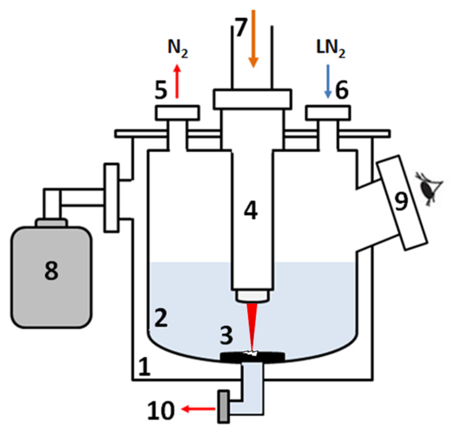
2. Materials and Methods
Electrochemical Measurements
3. Results
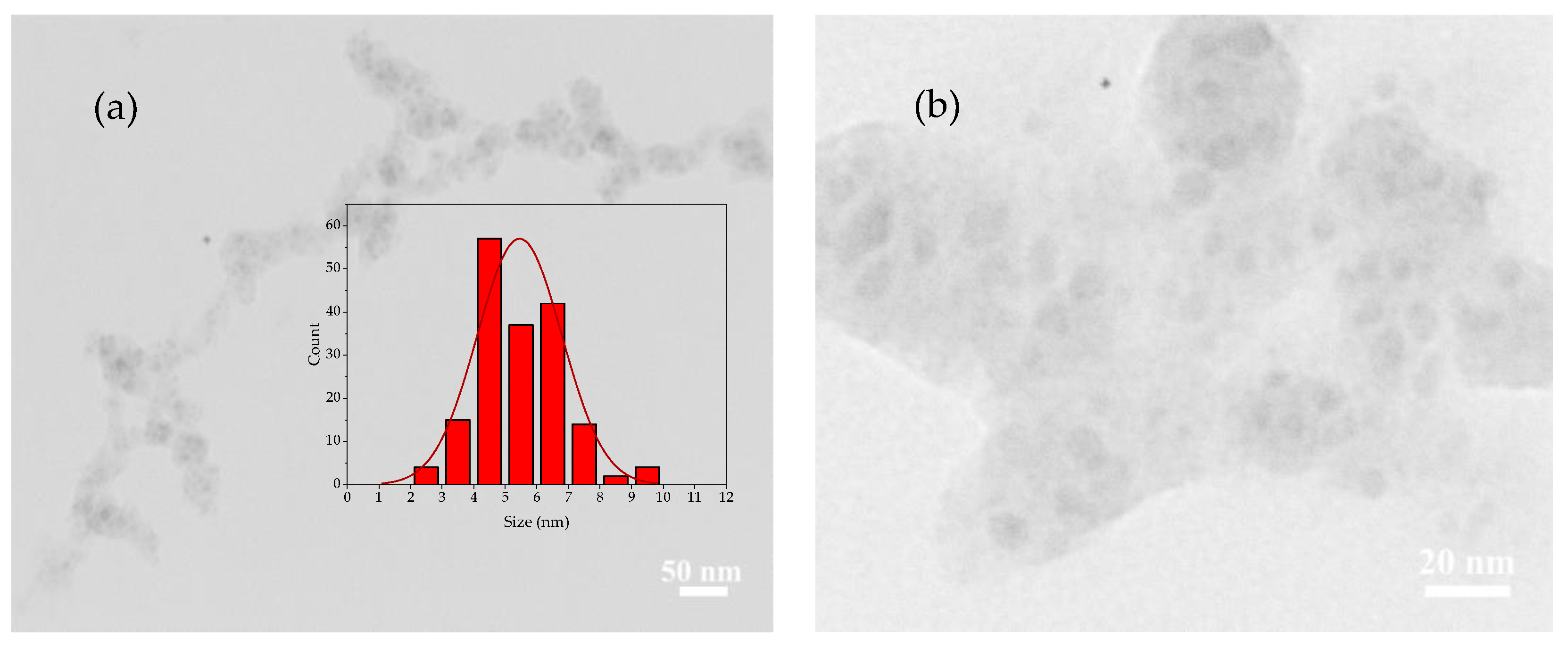
3.1. TEM Image
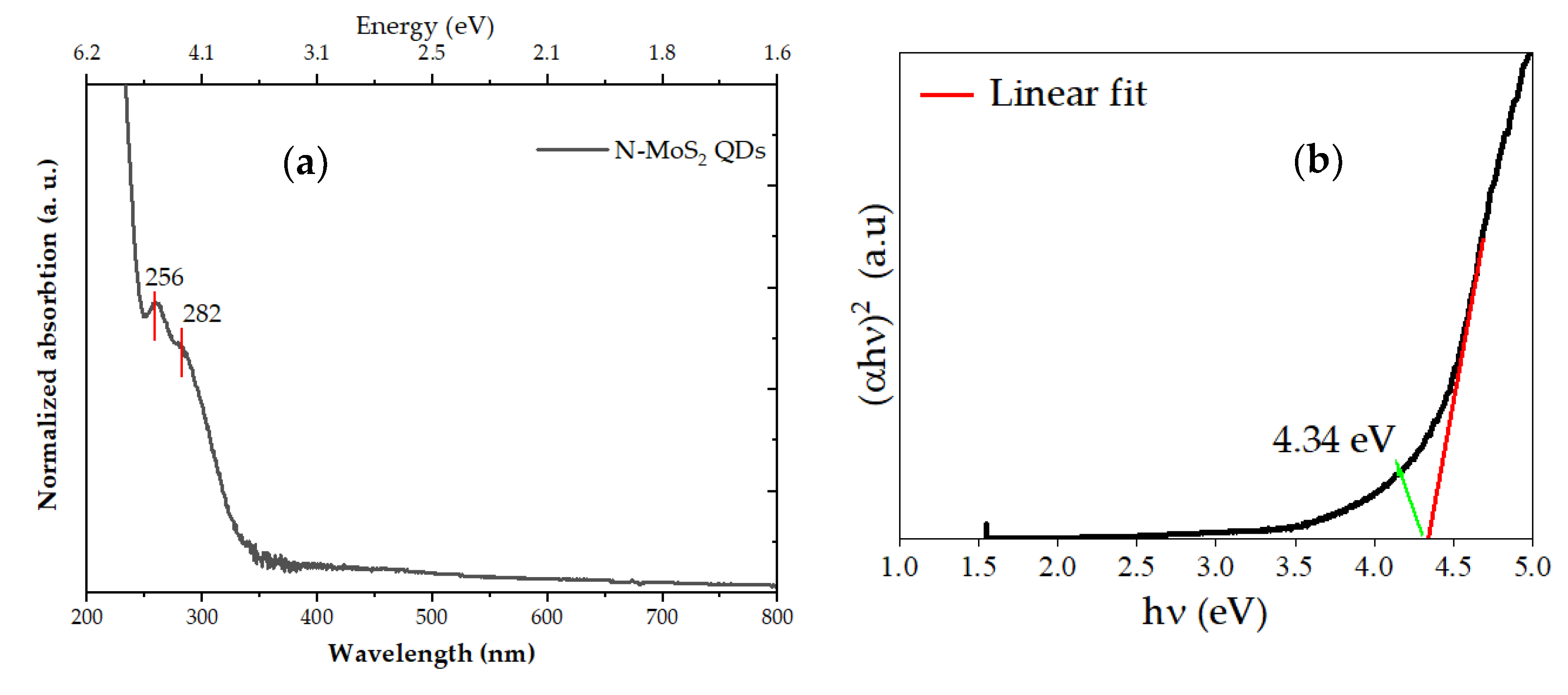
3.2. UV-Vis Spectroscopy and Tuck Plot
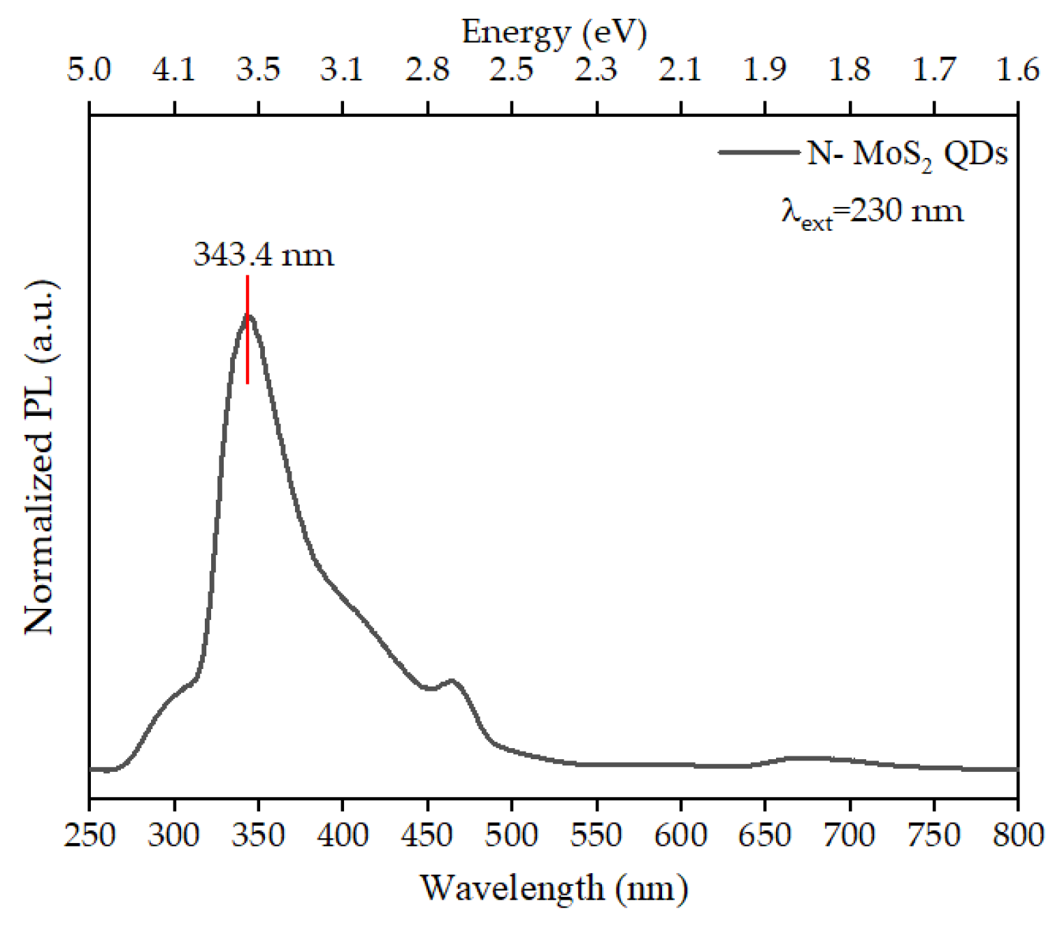
3.3. Photoluminescence Spectroscopy
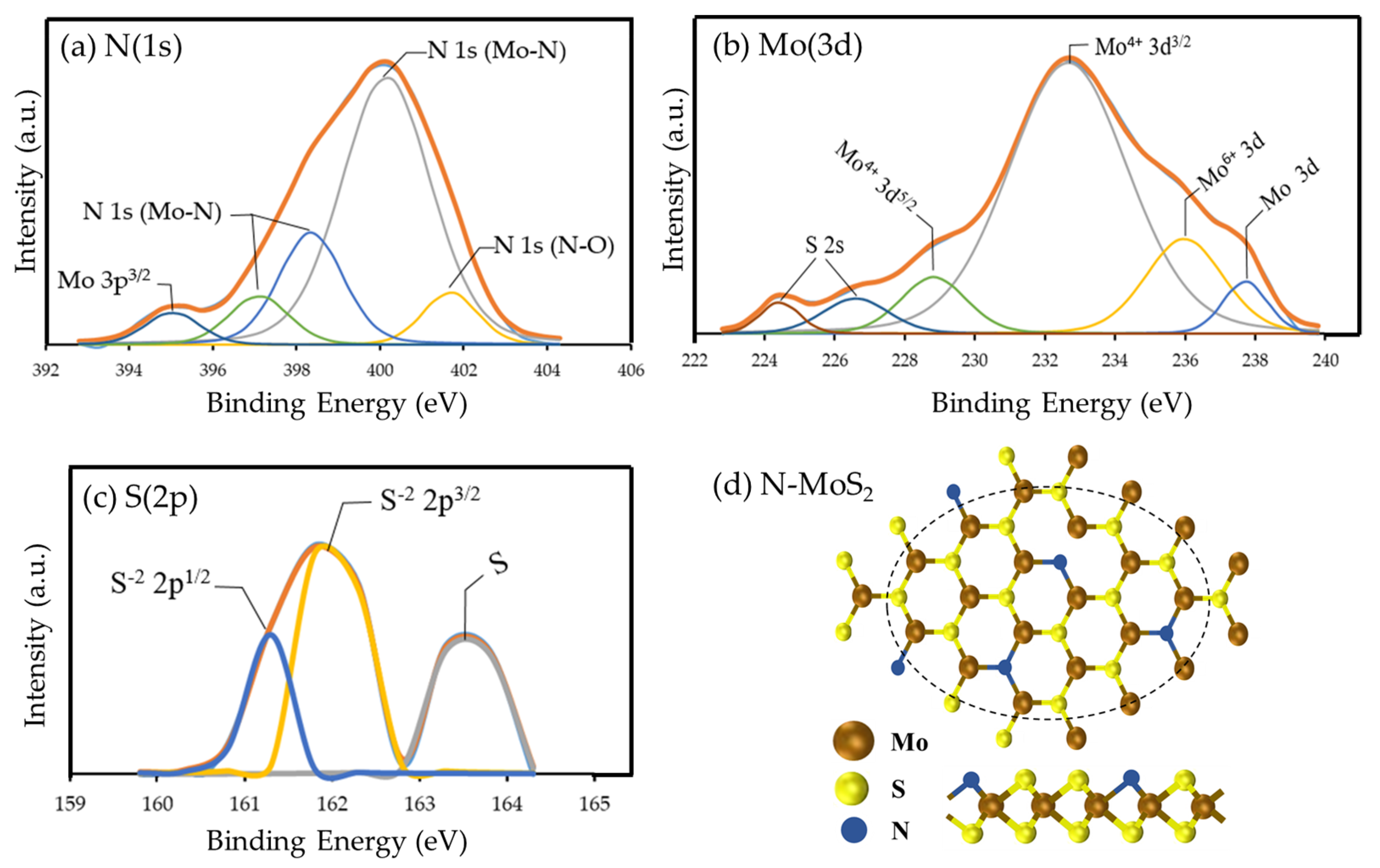
3.4. XPS
3.5. HER Activity of the Nitrogen Doped MoS2 QDs
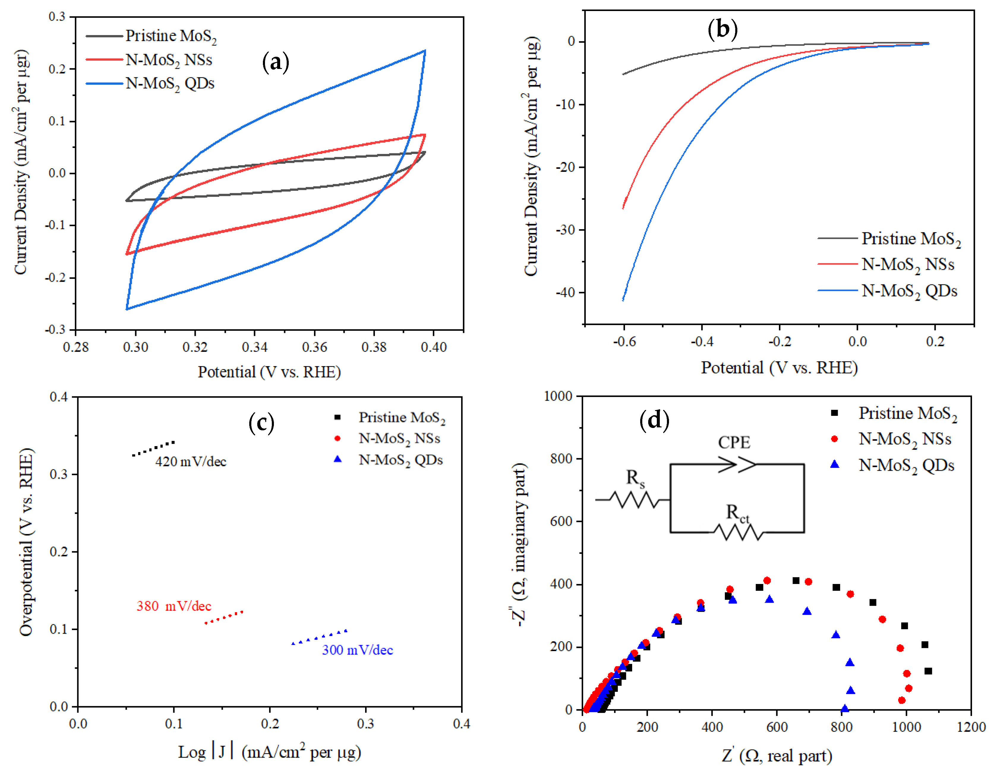
3.5.1. Cyclic Voltammetry (CV)
3.5.2. Linear Sweep Voltammetry (LSV)
3.5.3. Electrochemical Impedance Spectroscopy (EIS)
4. Discussion
5. Conclusions
Author Contributions
Funding
Data Availability Statement
Acknowledgments
Conflicts of Interest
References
- Baldovi, H.G.; Latorre-Sánchez, M.; Esteve-Adell, I.; Khan, A.; Asiri, A.M.; Kosa, S.A.; Garcia, H. Generation of MoS2 quantum dots by laser ablation of MoS2 particles in suspension and their photocatalytic activity for H2 generation. J. Nanopart. Res. 2016, 18, 240. [Google Scholar] [CrossRef]
- Liu, K.-K.; Zhang, W.; Lee, Y.-H.; Lin, Y.-C.; Chang, M.-T.; Su, C.-Y.; Chang, C.-S.; Li, H.; Shi, Y.; Zhang, H. Growth of large-area and highly crystalline MoS2 thin layers on insulating substrates. Nano Lett. 2012, 12, 1538–1544. [Google Scholar] [CrossRef] [PubMed]
- Huang, Y.; Wu, J.; Xu, X.; Ho, Y.; Ni, G.; Zou, Q.; Koon, G.K.W.; Zhao, W.; Neto, A.C.; Eda, G. An innovative way of etching MoS2: Characterization and mechanistic investigation. Nano Res. 2013, 6, 200–207. [Google Scholar] [CrossRef]
- Eda, G.; Yamaguchi, H.; Voiry, D.; Fujita, T.; Chen, M.; Chhowalla, M. Photoluminescence from chemically exfoliated MoS2. Nano Lett. 2011, 11, 5111–5116. [Google Scholar] [CrossRef]
- Hernandez, Y.; Nicolosi, V.; Lotya, M.; Blighe, F.M.; Sun, Z.; De, S.; McGovern, I.; Holland, B.; Byrne, M.; Gun’Ko, Y.K. High-yield production of graphene by liquid-phase exfoliation of graphite. Nat. Nanotechnol. 2008, 3, 563. [Google Scholar] [CrossRef]
- Novoselov, K.S.; Geim, A.K.; Morozov, S.V.; Jiang, D.; Zhang, Y.; Dubonos, S.V.; Grigorieva, I.V.; Firsov, A.A. Electric field effect in atomically thin carbon films. Science 2004, 306, 666–669. [Google Scholar] [CrossRef]
- Castellanos-Gomez, A.; Barkelid, M.; Goossens, A.; Calado, V.E.; van der Zant, H.S.; Steele, G.A. Laser-thinning of MoS2: On demand generation of a single-layer semiconductor. Nano Lett. 2012, 12, 3187–3192. [Google Scholar] [CrossRef]
- Gong, Y.; Li, B.; Ye, G.; Yang, S.; Zou, X.; Lei, S.; Jin, Z.; Bianco, E.; Vinod, S.; Yakobson, B.I. Direct growth of MoS2 single crystals on polyimide substrates. 2D Mater. 2017, 4, 021028. [Google Scholar] [CrossRef]
- Li, H.; Wu, H.; Yuan, S.; Qian, H. Synthesis and characterization of vertically standing MoS2 nanosheets. Sci. Rep. 2016, 6, 21171. [Google Scholar] [CrossRef]
- Yu, Y.; Li, C.; Liu, Y.; Su, L.; Zhang, Y.; Cao, L. Controlled scalable synthesis of uniform, high-quality monolayer and few-layer MoS2 films. Sci. Rep. 2013, 3, 1866. [Google Scholar] [CrossRef]
- Zhan, Y.; Liu, Z.; Najmaei, S.; Ajayan, P.M.; Lou, J. Large-area vapor-phase growth and characterization of MoS2 atomic layers on a SiO2 substrate. Small 2012, 8, 966–971. [Google Scholar] [CrossRef]
- Deokar, G.; Vignaud, D.; Arenal, R.; Louette, P.; Colomer, J.-F. Synthesis and characterization of MoS2 nanosheets. Nanotechnology 2016, 27, 075604. [Google Scholar] [CrossRef] [PubMed]
- Wang, R.; Shao, Q.; Yuan, Q.; Sun, P.; Nie, R.; Wang, X. Direct growth of high-content 1T phase MoS2 film by pulsed laser deposition for hydrogen evolution reaction. Appl. Surf. Sci 2020, 504, 144320. [Google Scholar] [CrossRef]
- Loh, T.A.; Chua, D.H. Pulsed laser fabricated few-layer MoS2 on silver. Chem. Phys. Lett. 2014, 610, 284–287. [Google Scholar] [CrossRef]
- Serna, M.I.; Moreno, S.; Higgins, M.; Choi, H.; Minary-Jolandan, M.; Quevedo-Lopez, M.A. Growth parameter enhancement for MoS2 thin films synthesized by pulsed laser deposition. Phys. Status Solidi C 2016, 13, 848–854. [Google Scholar] [CrossRef]
- Kang, K.; Xie, S.; Huang, L.; Han, Y.; Huang, P.Y.; Mak, K.F.; Kim, C.-J.; Muller, D.; Park, J. High-mobility three-atom-thick semiconducting films with wafer-scale homogeneity. Nature 2015, 520, 656–660. [Google Scholar] [CrossRef] [PubMed]
- Hu, J.; Zabinski, J.S.; Sanders, J.H.; Bultman, J.E.; Voevodin, A.A. Pulsed laser syntheses of layer-structured WS2 nanomaterials in water. J. Phys. Chem. B 2006, 110, 8914–8916. [Google Scholar] [CrossRef]
- Barcikowski, S.; Devesa, F.; Moldenhauer, K. Impact and structure of literature on nanoparticle generation by laser ablation in liquids. J. Nanopart. Res. 2009, 11, 1883. [Google Scholar] [CrossRef]
- Yang, G. Laser ablation in liquids: Applications in the synthesis of nanocrystals. Prog. Mater. Sci. 2007, 52, 648–698. [Google Scholar] [CrossRef]
- Mortazavi, S.Z.; Parvin, P.; Reyhani, A.; Golikand, A.N.; Mirershadi, S. Effect of laser wavelength at IR (1064 nm) and UV (193 nm) on the structural formation of palladium nanoparticles in deionized water. J. Phys. Chem. C 2011, 115, 5049–5057. [Google Scholar] [CrossRef]
- Mortazavi, S.Z.; Parvin, P.; Reyhani, A. Fabrication of graphene based on Q-switched Nd: YAG laser ablation of graphite target in liquid nitrogen. Laser Phys. Lett. 2012, 9, 547. [Google Scholar] [CrossRef]
- Shahi, F.; Parvin, P.; Mortazavi, S.Z.; Reyhani, A.; Soltannia, B.; Sadrzadeh, M.; Moradi, H.; Ojaghloo, A.; Moafi, A. Synthesis, Characterization, and Typical Application of Nitrogen-Doped MoS2 Nanosheets Based on Pulsed Laser Ablation in Liquid Nitrogen. Phys. Status Solidi A 2022, 219, 2100677. [Google Scholar] [CrossRef]
- Wilcoxon, J.; Newcomer, P.; Samara, G. Synthesis and optical properties of MoS2 and isomorphous nanoclusters in the quantum confinement regime. J. Appl. Phys. 1997, 81, 7934–7944. [Google Scholar] [CrossRef]
- Zong, X.; Na, Y.; Wen, F.; Ma, G.; Yang, J.; Wang, D.; Ma, Y.; Wang, M.; Sun, L.; Li, C. Visible light driven H2 production in molecular systems employing colloidal MoS2 nanoparticles as catalyst. Chem. Comm. 2009, 4536–4538. [Google Scholar] [CrossRef]
- Yin, W.; Yan, L.; Yu, J.; Tian, G.; Zhou, L.; Zheng, X.; Zhang, X.; Yong, Y.; Li, J.; Gu, Z. High-throughput synthesis of single-layer MoS2 nanosheets as a near-infrared photothermal-triggered drug delivery for effective cancer therapy. ACS Nano 2014, 8, 6922–6933. [Google Scholar] [CrossRef]
- Xiao, W.; Liu, P.; Zhang, J.; Song, W.; Feng, Y.P.; Gao, D.; Ding, J. Dual-Functional N Dopants in Edges and Basal Plane of MoS2 Nanosheets Toward Efficient and Durable Hydrogen Evolution. Adv. Energy Mater. 2017, 7, 1602086. [Google Scholar] [CrossRef]
- Enujekwu, F.M.; Zhang, Y.; Ezeh, C.I.; Zhao, H.; Xu, M.; Besley, E.; George, M.W.; Besley, N.A.; Do, H.; Wu, T. N-doping enabled defect-engineering of MoS2 for enhanced and selective adsorption of CO2: A DFT approach. Appl. Surf. Sci. 2021, 542, 148556. [Google Scholar] [CrossRef]
- Liu, Q.; Weijun, X.; Wu, Z.; Huo, J.; Liu, D.; Wang, Q.; Wang, S. The origin of the enhanced performance of nitrogen-doped MoS2 in lithium ion batteries. Nanotechnology 2016, 27, 175402. [Google Scholar] [CrossRef]
- Hu, C.; Yuan, C.; Hong, A.; Guo, M.; Yu, T.; Luo, X. Work function variation of monolayer MoS2 by nitrogen-doping. Appl. Phys. Lett. 2018, 113, 041602. [Google Scholar] [CrossRef]
- Fan, X.; Huang, Y.; Wang, H.; Zheng, F.; Tan, C.; Li, Y.; Lu, X.; Ma, Z.; Li, Q. Efficacious nitrogen introduction into MoS2 as bifunctional electrocatalysts for long-life Li-O2 batteries. Electrochim. Acta 2021, 369, 137653. [Google Scholar] [CrossRef]
- Yasin, G.; Ibrahim, S.; Ibraheem, S.; Ali, S.; Iqbal, R.; Kumar, A.; Tabish, M.; Slimani, Y.; Nguyen, T.A.; Xu, H. Defective/graphitic synergy in a heteroatom-interlinked-triggered metal-free electrocatalyst for high-performance rechargeable zinc–air batteries. J. Mater. Chem. A 2021, 9, 18222–18230. [Google Scholar] [CrossRef]
- Yasin, G.; Arif, M.; Ma, J.; Ibraheem, S.; Yu, D.; Zhang, L.; Liu, D.; Dai, L. Self-templating synthesis of heteroatom-doped large-scalable carbon anodes for high-performance lithium-ion batteries. Inorg. Chem. Front. 2022, 9, 1058–1069. [Google Scholar] [CrossRef]
- Yang, Q.; Wang, Z.; Dong, L.; Zhao, W.; Jin, Y.; Fang, L.; Hu, B.; Dong, M. Activating MoS2 with super-high nitrogen-doping concentration as efficient catalyst for hydrogen evolution reaction. J. Phys. Chem. C 2019, 123, 10917–10925. [Google Scholar] [CrossRef]
- Bolar, S.; Shit, S.; Murmu, N.C.; Samanta, P.; Kuila, T. Activation strategy of MoS2 as HER electrocatalyst through doping-induced lattice strain, band gap engineering, and active crystal plane design. ACS Appl. Mater. Interfaces 2021, 13, 765–780. [Google Scholar] [CrossRef]
- Qin, S.; Lei, W.; Liu, D.; Chen, Y. Advanced N-doped mesoporous molybdenum disulfide nanosheets and the enhanced lithium-ion storage performance. J. Mater. Chem. A 2016, 4, 1440–1445. [Google Scholar] [CrossRef]
- Shi, Y.; Zhou, Y.; Yang, D.-R.; Xu, W.-X.; Wang, C.; Wang, F.-B.; Xu, J.-J.; Xia, X.-H.; Chen, H.-Y. Energy level engineering of MoS2 by transition-metal doping for accelerating hydrogen evolution reaction. J. ACS 2017, 139, 15479–15485. [Google Scholar] [CrossRef]
- Guo, X.; Wan, X.; Liu, Q.; Li, Y.; Li, W.; Shui, J. Phosphated IrMo bimetallic cluster for efficient hydrogen evolution reaction. Escience 2022, 2, 304–310. [Google Scholar] [CrossRef]
- Zhu, J.; Wang, Z.; Yu, H.; Li, N.; Zhang, J.; Meng, J.; Liao, M.; Zhao, J.; Lu, X.; Du, L. Argon plasma induced phase transition in monolayer MoS2. J. Am. Chem. Soc. 2017, 139, 10216–10219. [Google Scholar] [CrossRef]
- Wang, M.-Q.; Tang, C.; Ye, C.; Duan, J.; Li, C.; Chen, Y.; Bao, S.-J.; Xu, M. Engineering the nanostructure of molybdenum nitride nanodot embedded N-doped porous hollow carbon nanochains for rapid all pH hydrogen evolution. J. Mater. Chem. A 2018, 6, 14734–14741. [Google Scholar] [CrossRef]
- Zhang, P.; Xu, B.; Chen, G.; Gao, C.; Gao, M. Large-scale synthesis of nitrogen doped MoS2 quantum dots for efficient hydrogen evolution reaction. Electrochim. Acta 2018, 270, 256–263. [Google Scholar] [CrossRef]
- Zhang, R.; Zhang, M.; Yang, H.; Li, G.; Xing, S.; Li, M.; Xu, Y.; Zhang, Q.; Hu, S.; Liao, H. Creating Fluorine-Doped MoS2 Edge Electrodes with Enhanced Hydrogen Evolution Activity. Small Methods 2021, 5, 2100612. [Google Scholar] [CrossRef]
- Xiao, Z.; Luo, S.; Duan, W.; Zhang, X.; Han, S.; Liu, Y.; Yang, L.; Lin, S. Doughty-electronegative heteroatom-induced defective MoS2 for the hydrogen evolution reaction. Front. Chem. 2022, 10. [Google Scholar] [CrossRef]
- Rivera, A.M.; Gaur, A.P.; Sahoo, S.; Katiyar, R.S. Studies on chemical charge doping related optical properties in monolayer WS2. J. Appl. Phys. 2016, 120, 105102. [Google Scholar] [CrossRef]
- Yang, X.; Yu, H.; Guo, X.; Ding, Q.; Pullerits, T.; Wang, R.; Zhang, G.; Liang, W.; Sun, M. Plasmon-exciton coupling of monolayer MoS2-Ag nanoparticles hybrids for surface catalytic reaction. Mater. Today Energy 2017, 5, 72–78. [Google Scholar] [CrossRef]
- Sunitha, A.; Hajara, P.; Shaji, M.; Jayaraj, M.; Saji, K. Luminescent MoS2 quantum dots with reverse saturable absorption prepared by pulsed laser ablation. J. Lumin. 2018, 203, 313–321. [Google Scholar] [CrossRef]
- Li, B.; Jiang, L.; Li, X.; Ran, P.; Zuo, P.; Wang, A.; Qu, L.; Zhao, Y.; Cheng, Z.; Lu, Y. Preparation of monolayer MoS2 quantum dots using temporally shaped femtosecond laser ablation of bulk MoS2 targets in water. Sci. Rep. 2017, 7, 1–12. [Google Scholar] [CrossRef]
- Nguyen, V.; Dong, Q.; Yan, L.; Zhao, N.; Le, P.H. Facile synthesis of photoluminescent MoS2 and WS2 quantum dots with strong surface-state emission. J. Lumin. 2019, 214, 116554. [Google Scholar] [CrossRef]
- Alexaki, K.; Kostopoulou, A.; Sygletou, M.; Kenanakis, G.; Stratakis, E. Unveiling the Structure of MoSx Nanocrystals Produced upon Laser Fragmentation of MoS2 Platelets. ACS Omega 2018, 3, 16728–16734. [Google Scholar] [CrossRef]
- Madugundo, R.; Rao, N.V.R.; Schönhöbel, A.M.; Salazar, D.; El-Gendy, A.A. Recent developments in nanostructured permanent magnet materials and their processing methods. Magn. Nanostruct. Mater. 2018, 1, 157–198. [Google Scholar]
- Chen, R.; Yang, C.; Cai, W.; Wang, H.-Y.; Miao, J.; Zhang, L.; Chen, S.; Liu, B. Use of platinum as the counter electrode to study the activity of nonprecious metal catalysts for the hydrogen evolution reaction. ACS Energy Lett. 2017, 2, 1070–1075. [Google Scholar] [CrossRef]
- Cao, H.; Wang, H.; Huang, Y.; Sun, Y.; Shi, S.; Tang, M. Quantification of gold (III) in solution and with a test stripe via the quenching of the fluorescence of molybdenum disulfide quantum dots. Microchim. Acta 2017, 184, 91–100. [Google Scholar] [CrossRef]
- Murugan, A.V.; Kale, B.; Kulkarni, A.V.; Kunde, L.B.; Saaminathan, V. Novel approach to control CdS morphology by simple microwave-solvothermal method. J. Mater. Sci. 2005, 16, 295–299. [Google Scholar] [CrossRef]
- Tauc, J.; Grigorovici, R.; Vancu, A. Optical properties and electronic structure of amorphous germanium. Phys. Status Solidi B 1966, 15, 627–637. [Google Scholar] [CrossRef]
- Dileep, K.; Sahu, R.; Sarkar, S.; Peter, S.C.; Datta, R. Layer specific optical band gap measurement at nanoscale in MoS2 and ReS2 van der Waals compounds by high resolution electron energy loss spectroscopy. J. Appl. Phys. 2016, 119, 114309. [Google Scholar] [CrossRef]
- Mahdavi, M.; Kimiagar, S.; Abrinaei, F. Preparation of Few-Layered Wide Bandgap MoS2 with Nanometer Lateral Dimensions by Applying Laser Irradiation. Crystals 2020, 10, 164. [Google Scholar] [CrossRef]
- Ren, X.; Pang, L.; Zhang, Y.; Ren, X.; Fan, H.; Liu, S.F. One-step hydrothermal synthesis of monolayer MoS2 quantum dots for highly efficient electrocatalytic hydrogen evolution. J. Mater. Chem. A 2015, 3, 10693–10697. [Google Scholar] [CrossRef]
- Panchu, S.J.; Raju, K.; Swart, H.C.; Chokkalingam, B.; Maaza, M.; Henini, M.; Moodley, M.K. Luminescent MoS2 quantum dots with tunable operating potential for energy-enhanced aqueous supercapacitors. ACS Omega 2021, 6, 4542–4550. [Google Scholar] [CrossRef]
- Park, M.J.; Yi, S.-G.; Kim, J.H.; Yoo, K.-H. Metal–insulator crossover in multilayered MoS2. Nanoscale 2015, 7, 15127–15133. [Google Scholar] [CrossRef]
- Splendiani, A.; Sun, L.; Zhang, Y.; Li, T.; Kim, J.; Chim, C.-Y.; Galli, G.; Wang, F. Emerging photoluminescence in monolayer MoS2. Nano Lett. 2010, 10, 1271–1275. [Google Scholar] [CrossRef]
- Wang, D.; Li, X.-B.; Han, D.; Tian, W.Q.; Sun, H.-B. Engineering two-dimensional electronics by semiconductor defects. Nano Today 2017, 16, 30–45. [Google Scholar] [CrossRef]
- Wu, Z.; Ni, Z. Spectroscopic investigation of defects in two-dimensional materials. Nanophotonics 2017, 6, 1219–1237. [Google Scholar] [CrossRef]
- Kang, N.; Paudel, H.P.; Leuenberger, M.N.; Tetard, L.; Khondaker, S.I. Photoluminescence quenching in single-layer MoS2 via oxygen plasma treatment. J. Phys. Chem. C 2014, 118, 21258–21263. [Google Scholar] [CrossRef]
- Nan, H.; Wang, Z.; Wang, W.; Liang, Z.; Lu, Y.; Chen, Q.; He, D.; Tan, P.; Miao, F.; Wang, X. Strong photoluminescence enhancement of MoS2 through defect engineering and oxygen bonding. ACS Nano 2014, 8, 5738–5745. [Google Scholar] [CrossRef]
- Kwak, I.H.; Kwon, I.S.; Abbas, H.G.; Jung, G.; Lee, Y.; Debela, T.T.; Yoo, S.J.; Kim, J.-G.; Park, J.; Kang, H.S. Nitrogen-rich 1T′-MoS2 layered nanostructures using alkyl amines for high catalytic performance toward hydrogen evolution. Nanoscale 2018, 10, 14726–14735. [Google Scholar] [CrossRef] [PubMed]
- Sanjinés, R.; Wiemer, C.; Almeida, J.; Levy, F. Valence band photoemission study of the Ti Mo N system. Thin Solid Films 1996, 290, 334–338. [Google Scholar] [CrossRef]
- Zhou, W.; Hou, D.; Sang, Y.; Yao, S.; Zhou, J.; Li, G.; Li, L.; Liu, H.; Chen, S. MoO2 nanobelts@ nitrogen self-doped MoS2 nanosheets as effective electrocatalysts for hydrogen evolution reaction. J. Mater. Chem. A 2014, 2, 11358–11364. [Google Scholar] [CrossRef]
- Wu, F.-Y.; Cheng, Y.-S.; Wang, D.-M.; Li, M.-L.; Lu, W.-S.; Xu, X.-Y.; Zhou, X.-H.; Wei, X.-W. Nitrogen-doped MoS2 quantum dots: Facile synthesis and application for the assay of hematin in human blood. Mater. Sci. Eng. C 2020, 112, 110898. [Google Scholar] [CrossRef]
- Shuxian, Z.; Hall, W.K.; Ertl, G.; Knözinger, H. X-ray photoemission study of oxygen and nitric oxide adsorption on MoS2. Appl. Catal. 1986, 100, 167–175. [Google Scholar] [CrossRef]
- Baby, M.; Kumar, K.R. Synthesis and characterisation of MoS2 quantum dots by liquid nitrogen quenching. Mater. Sci. Technol. 2019, 35, 1416–1427. [Google Scholar] [CrossRef]
- Benoist, L.; Gonbeau, D.; Pfister-Guillouzo, G.; Schmidt, E.; Meunier, G.; Levasseur, A. XPS analysis of oxido-reduction mechanisms during lithium intercalation in amorphous molybdenum oxysulfide thin films. Solid State Ion. 1995, 76, 81–89. [Google Scholar] [CrossRef]
- Anwar, M.; Hogarth, C.; Bulpett, R. Effect of substrate temperature and film thickness on the surface structure of some thin amorphous films of MoO3 studied by X-ray photoelectron spectroscopy (ESCA). J. Mater. Sci. 1989, 24, 3087–3090. [Google Scholar] [CrossRef]
- Kuo, D.-H.; Abdullah, H.; Gultom, N.S.; Hu, J.-Y. Ag-decorated MoSx laminar-film electrocatalyst made with simple and scalable magnetron sputtering technique for hydrogen evolution: A defect model to explain the enhanced electron transport. ACS Appl. Mater. Interfaces 2020, 12, 35011–35021. [Google Scholar] [CrossRef] [PubMed]
- Tang, P.; Jiao, J.; Fan, Q.; Wang, X.; Agrawal, V.; Xu, Q. Interlayer spacing engineering in N doped MoS2 for efficient lithium ion storage. Mater. Chem. Phys. 2021, 261, 124166. [Google Scholar] [CrossRef]
- Bayat, A.; Zirak, M.; Saievar-Iranizad, E. Vertically aligned MoS2 quantum dots/nanoflakes heterostructure: Facile deposition with excellent performance toward hydrogen evolution reaction. ACS Sustain. Chem. Eng. 2018, 6, 8374–8382. [Google Scholar] [CrossRef]
- Azcatl, A.; Qin, X.; Prakash, A.; Zhang, C.; Cheng, L.; Wang, Q.; Lu, N.; Kim, M.J.; Kim, J.; Cho, K. Covalent nitrogen doping and compressive strain in MoS2 by remote N2 plasma exposure. Nano Lett. 2016, 16, 5437–5443. [Google Scholar] [CrossRef] [PubMed]
- Li, R.; Yang, L.; Xiong, T.; Wu, Y.; Cao, L.; Yuan, D.; Zhou, W. Nitrogen doped MoS2 nanosheets synthesized via a low-temperature process as electrocatalysts with enhanced activity for hydrogen evolution reaction. J. Power Sources 2017, 356, 133–139. [Google Scholar] [CrossRef]


| Laser | Wavelength | Medium | Sizes | UV-Vis Peak [nm] | PL Peak [nm] | Ref. |
|---|---|---|---|---|---|---|
| Nd:YAG | 1064, 532, 355 nm 6–7 ns | Water | 2–30 nm | 209.8 and 211.4 | 553–563 | [45] |
| Nd:YAG | 532 nm–7 ns | Acetonitrile | 3–6 layers 5 to 20 nm | 450 | 440 to 530 | [1] |
| Ti:sapphire | 800 nm–50 fs | Deionized (DI) water | 1–120 nm 1–5 nm | λ < 300 | 340 to 450 | [46] |
| Ti:sapphire | 800 nm–150 fs | Diethylamine | 1.8 nm | 275 | ~420 | [47] |
| Yb:KGW | 1026 nm–170 fs | Water | - | - | 448 nm | [48] |
| Nd:YAG | 1064 nm–10 ns | LN2 | 5.5 nm | 256 and 282 nm | 300 to 450 nm | This work |
| Sample | Overpotential (V) at −4 mA/cm2 per µg | Overpotential (V) at −10 mA/cm2 per µg | J (mA/cm2 per µg) at η = 0.6 V | Tafel Slope (mV/dec) | Rct (kΩ) |
|---|---|---|---|---|---|
| Pristine MoS2 | −0.55 | - | 5.20 | 420 | 1.162 |
| N-MoS2 NSs | −0.29 | −0.45 | 26.25 | 380 | 1.131 |
| N-MoS2 QDs | −0.20 | −0.35 | 41.42 | 300 | 0.897 |
Disclaimer/Publisher’s Note: The statements, opinions and data contained in all publications are solely those of the individual author(s) and contributor(s) and not of MDPI and/or the editor(s). MDPI and/or the editor(s) disclaim responsibility for any injury to people or property resulting from any ideas, methods, instructions or products referred to in the content. |
© 2022 by the authors. Licensee MDPI, Basel, Switzerland. This article is an open access article distributed under the terms and conditions of the Creative Commons Attribution (CC BY) license (https://creativecommons.org/licenses/by/4.0/).
Share and Cite
Shahi, F.; Parvin, P.; Mortazavi, S.Z.; Reyhani, A.; Sadrzadeh, M.; Moafi, A.; Ebrahimi, M.; Aghaei, M. In-Situ Generation of Nitrogen-Doped MoS2 Quantum Dots Using Laser Ablation in Cryogenic Medium for Hydrogen Evolution Reaction. Energies 2023, 16, 455. https://doi.org/10.3390/en16010455
Shahi F, Parvin P, Mortazavi SZ, Reyhani A, Sadrzadeh M, Moafi A, Ebrahimi M, Aghaei M. In-Situ Generation of Nitrogen-Doped MoS2 Quantum Dots Using Laser Ablation in Cryogenic Medium for Hydrogen Evolution Reaction. Energies. 2023; 16(1):455. https://doi.org/10.3390/en16010455
Chicago/Turabian StyleShahi, Fatemeh, Parviz Parvin, Seyedeh Zahra Mortazavi, Ali Reyhani, Mohtada Sadrzadeh, Ali Moafi, Mahdi Ebrahimi, and Mohammadreza Aghaei. 2023. "In-Situ Generation of Nitrogen-Doped MoS2 Quantum Dots Using Laser Ablation in Cryogenic Medium for Hydrogen Evolution Reaction" Energies 16, no. 1: 455. https://doi.org/10.3390/en16010455
APA StyleShahi, F., Parvin, P., Mortazavi, S. Z., Reyhani, A., Sadrzadeh, M., Moafi, A., Ebrahimi, M., & Aghaei, M. (2023). In-Situ Generation of Nitrogen-Doped MoS2 Quantum Dots Using Laser Ablation in Cryogenic Medium for Hydrogen Evolution Reaction. Energies, 16(1), 455. https://doi.org/10.3390/en16010455