Article

Comparative Study of Non-Rare-Earth and Rare-Earth PM Motors for EV Applications

1
School of Electrical and Electronic Engineering, Huazhong University of Science and Technology, Wuhan 430074, China
2
Department of Industrial Engineering, University of Padova, 35122 Padova, Italy
*
Author to whom correspondence should be addressed.
Energies 2022, 15(8), 2711; https://doi.org/10.3390/en15082711
Submission received: 9 January 2022 / Revised: 18 March 2022 / Accepted: 26 March 2022 / Published: 7 April 2022
(This article belongs to the Special Issue High Performance Permanent Magnet Synchronous Motor Drives)

Abstract

:
Recently, non-rare-earth motors are attracting more and more attention due to the booming of the electric vehicle (EV) market and, more importantly, the increasing price of the rare-earth magnet material. This paper focuses on the performance comparison among a commercial interior permanent magnet (IPM) motor and two non-rare-earth motors, including a synchronous reluctance motor (SynRM) and a permanent-magnet-assisted synchronous reluctance motor (PMaSynRM). The design procedure to develop a high-torque-density, low-torque-ripple and high-efficiency SynRM is presented. Combined with a developed automatic modeling and simulation procedure, the finite element analysis (FEA)-based differential evolution (DE) algorithm is introduced for the SynRM rotor optimization. In order to fully inspire the potential of the SynRM, a novel method to optimize the motor split ratio is proposed under the constraint of the copper loss. In addition, different slot–pole combinations are investigated to maximize the motor torque, and the rotor structure is also dealt with towards the centrifugal stress at the maximum operating speed. Finally, the motor performance comparison is carried out, and the results show that although the SynRM achieves almost 61% cost savings, its poor torque capability, power factor and flux weakening (FW) capability are non-negligible defects. On the contrary, the PMaSynRM exhibits excellent features for the EV applications in terms of cost, torque density, efficiency and FW capability. This paper presents a novel split ratio optimization method for the optimal SynRM/PMaSynRM design and demonstrates the characteristics of the IPM motors, SynRMs and PMaSynRMs for EV applications.

Graphical Abstract

1. Introduction

With the growth of global warming and air pollution, electrical traction systems as gaining more and more interest in both the academic and industrial fields. It is remarkable that the popularity of electric vehicles (EVs) and hybrid electric vehicles (HEVs) has expanding significantly in the last decade. The electrical traction motor represents the heart of the energy conversion process. Among various machine topologies, the interior permanent magnet (IPM) motor has been recognized as the most promising candidate [1,2,3]. On the other hand, some challenges exist in IPM motors, i.e., high production cost and high risk of irreversible demagnetization. Most importantly, a worldwide concern over the price volatility and availability of rare-earth magnets is growing. Therefore, many researchers are focused on alternative non-rare-earth traction drives [4,5].
The induction motor (IM) firstly comes to the researchers’ minds, mainly due to its low cost, robust structure and well-established manufacturing techniques [6,7]. The wide flux-weakening range makes it very suitable for EV applications. Nevertheless, the low power density and inferior efficiency are potential challenges of IMs [4]. The switched reluctance machine (SRM) is also a good candidate in terms of simple and robust rotor structure and possible operation in high temperatures or high rotational speeds [8,9,10]. The major disadvantage is acoustic noise and vibration, which becomes significant at high speeds and high loads [11].
The synchronous reluctance motor (SynRM), as shown in Figure 1, has attracted more and more attention in recent years, even though it has not been widely used in the traction drive field. With 30 years of development, it has achieved the merits of having low cost, high efficiency, low maintenance, high reliability and high temperature resistance [12,13]. In addition, it is also characterized by no back electromagnetic force (EMF), leading to an inherent fault tolerance capability. All these features reveal that the SynRM is an attractive alternative for electrical mobility. Previously, high torque ripple was one of the major concerns for the SynRM. However, it has been proved to be reduced to a quite low level with the appropriate choice of the barrier end angles [14]. The absence of magnets also makes it difficult for the SynRM to achieve a torque density and power factor as high as the IPM motor’s. Extensive efforts have been made on the rotor barrier design to improve the torque density, including fluid-shaped [15], rectangular-shaped [16], circular-shaped [17], U-shaped [17] and hyperbolic-shaped [18] flux barriers. Dual rotor design is also beneficial for improving the torque density [19]. Additionally, it is easy to improve its torque density and power factor by adopting low-cost ferrite or high-performance rare-earth magnet materials into the flux barriers of the SynRMs, i.e., the permanent-magnet-assisted synchronous reluctance motor (PMaSynRM) [20,21,22]. In order to maximize the reluctance torque component, the PMaSynRM design generally starts with the optimization of the SynRM, as evidenced in [23,24].
The investigation of SynRM or PMaSynRM for EV applications has been carried out in literature. A comparative study of SynRM, PMaSynRM and the benchmark Prius 2010 IPM motor was conducted in [25], in terms of electromagnetic performance and material cost. The slot–pole combination and copper loss are kept constant for these designs. The SynRM design utilizing dual-phase magnetic materials can be competitive with an IPM motor when considering the power density and efficiency [26]. A carbon-fiber-wrapped SynRM was designed and tested according to the US DOE Freedom Car 2020 specifications, which aims to reduce the flux leakage and improve the saliency ratio [27]. A novel magnet-axis-shifted hybrid PM machine was proposed for EV application in [28]. It achieved a higher torque capability, wider high-efficiency operation range but higher cogging torque and iron losses than that of the benchmark BMW i3 IPM machine. In addition, the comparison of the ferrite and rare-earth-based PM machines was summarized in [22], and both the advantages and disadvantages were highlighted.
In [15], an automatic modeling and simulation procedure of SynRM was proposed, considering different flux barrier numbers and barrier end angles. This procedure is then extended to be coupled with the differential evolution (DE) algorithm to achieve an automatic SynRM rotor optimization. By using this tool, this paper aims to design a SynRM and a PMaSynRM according to the dimension of Lexus LS 600h IPM motor, so as to achieve a detailed performance comparison. The following sections will be organized as follows: The SynRM rotor optimization process using finite element analysis (FEA)-based DE algorithm is introduced in Section 2. After that, the design procedure for the whole machine geometry, which includes split ratio optimization, slot–pole combination selection, rotor optimization and rotor structure improvement, is proposed in Section 3. Then, the performance comparison between the designed SynRM/PMaSynRM and the benchmark IPM motor is carried out in Section 4, and finally, the conclusions are drawn in Section 5.

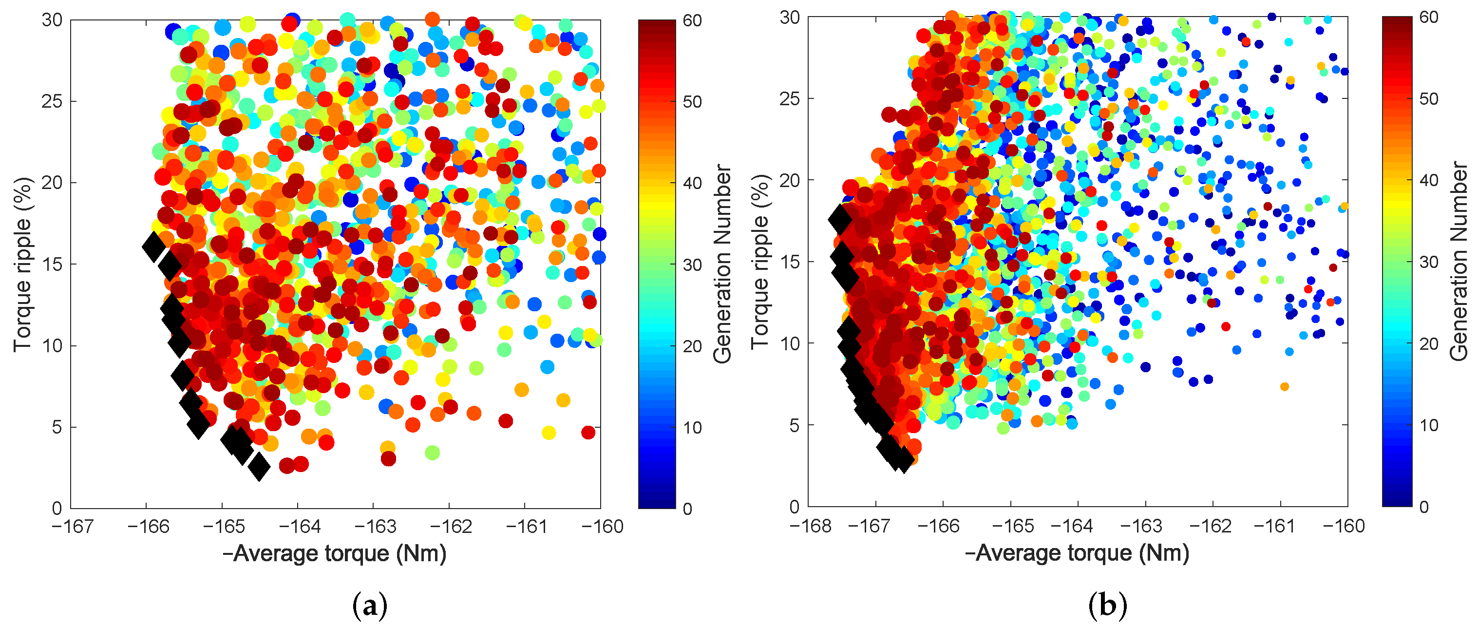
2. SynRM Rotor Optimization with DE Algorithm

The Lexus LS 600h IPM motor is selected as the reference in this paper, with its performance deeply evaluated and tested in [29]. Main dimensions of the Lexus LS 600h IPM motor are listed in Table 1. These dimensions are the baselines of the SynRM design. It is noticed that the Lexus LS 600h IPM motor achieves 110 kW within the stator temperature limit of 150 C for a transient time of 18 s when the current is 330 A p e a k at the speed of 4500 rpm [29]. Then, the current limit is set to be 330 A p e a k , and the calculated current density and stator fill factor are 25 A/mm 2 and 0.42, respectively. This operation point is chosen as the reference for the following design.
In order to present a fair comparison with the Lexus LS 600h IPM motor, the SynRM is constrained to satisfy some dimension limits of the benchmark motor. Firstly, the rotor is replaced by a SynRM topology, while the stator remains the same. For the design of SynRM, the most challenging and creative aspect lies in the rotor design by dramatically increasing the rotor’s anisotropy to improve the torque density and selecting proper barrier end angles for torque ripple suppression. Key efforts to achieve these objectives include parametric machine modeling and optimization strategy. In [15], an automatic modeling and simulation procedure has been developed. Hereafter, it is combined with differential evolution (DE) algorithm to achieve the optimal SynRM rotor design.

2.1. DE Algorithm

As is well-known, the DE algorithm is a population-based stochastic searching method, suitable for combinatorial optimization problems [30,31,32]. It was firstly proposed in the mid-1990s and has been applied for machine optimization problems in recent years [33,34].
The algorithm includes the processes of initialization, mutation, crossover and selection. At the beginning, the initial parameter vectors of the individuals are randomly generated, which covers the entire parameter space. After evaluating the fitness of each member, parameter vectors of a new generation are created through the operators of mutation and crossover. Then, an explicit one-to-one survivor selection is carried out. Once the new population is generated, the process of mutation, crossover and selection is repeated until the convergence of the algorithm or a specified number of generations is reached. This procedure is illustrated in Figure 2, and detailed explanations are referred to in [30,31].
The process of mutation expands the search space by using a scale factor F (i.e., mutation ratio) to recombine a random vector differential with the base individual. A high value of F helps to avoid the local optimum, while it simultaneously sacrifices the speed of convergence. Therefore, the value of F is seldom greater than 1.0 . The process of crossover, which is performed with a probability of C R (i.e., crossover ratio), mixes successful solutions from the previous generation with current donors. In the extreme circumstance, C R = 1 indicates a full consideration of the current donors, which undoubtedly increases the population diversity but makes the difference between the donor vector and the previous vector larger. The rule of thumb values of the mutation and crossover ratios is recommended as F [ 0.5 , 1.0 ] and C R [ 0.5 , 1.0 ] [31]. In this problem, they are set to be F = 0.9 and C R = 0.7 , respectively.

2.2. SynRM Rotor with Three and Four Flux Barriers

The preliminary design of the SynRM is carried out by fixing the same stator as the Lexus LS 600h IPM motor. The rotor pole number and airgap thickness remain the same as the Lexus LS 600h IPM. The DE algorithm is combined with finite element analysis (FEA) for the rotor optimization, which aims to have a low-torque-ripple and high-torque design. The optimization procedure is illustrated in Figure 2.
As one of the key issues for geometry optimization, SynRM rotor parametrization usually presents many degrees of freedom. The automatic drawing procedure proposed in [15], however, requires only two main parameters for SynRM rotor modeling, i.e., insulation ratio k a i r and barrier end angle θ b . The streamlined flux barrier shape is adopted, which is set to be parallel to the d-axis flux lines and perpendicular to the q-axis flux lines when saturation is neglected. This allows one to theoretically maximize the d-axis inductance and minimize the q-axis inductance, thus achieving a high saliency ratio and high torque. Points on the q-axis, as shown in Figure 3, are selected as starting points of the flux barrier boundaries, and their coordinates are computed through the width of each flux barrier t b i and the width of each iron path w f e i . By introducing the insulation ratio and the barrier end angles, w f e i is calculated according to the d-axis flux density distribution, and t b i is obtained based on the q-axis magnetic voltage drop across the corresponding flux barrier. Related equations and some tuning tricks to overcome geometric issues can be referred to [15]. As a result, a robust and fast modeling framework for SynRM rotor design is created.
Since this automatic modeling procedure is developed in a FEA tool, machine performance is then obtained by FEA simulation and post-processing. Therefore, the SynRM rotor optimization can be achieved by combining the automatic modeling and simulation procedure with DE algorithm. The evaluation of individuals is completed by calling the FEA tool and finding the Pareto front, which are described in Figure 2. As previously mentioned, the optimization parameters are the insulation ratio k a i r and the barrier end angles θ b . In fact, the number of barrier end angles depends on the number of flux barriers per pole. For example, the parameters definition of a three-barrier SynRM rotor is shown in Figure 3. The optimization objectives are focused on average torque and torque ripple, aiming at a low-torque-ripple and high-torque design. The torque ripple is defined as the ratio of peak-to-peak value to the average torque.
According to the previous investigation [15], three and four flux barriers per pole are studies in order to balance the output torque and manufacture difficulties. The optimization result for SynRM with three barriers per pole is plotted in Figure 4a, and the corresponding result of the four barriers per pole motor is shown in Figure 4b. Individuals are marked with dots on the average torque and torque ripple plane, where different colors indicate different generation numbers. For each individual, the current angle is tuned to achieve the maximum torque within the current limit. It is notable that the sign of the average torque is reversed because the aim of this optimization is to minimize each objective. The better solutions move towards the bottom left of the plane. The black diamonds form the Pareto front, which views clearly how each objective is penalized by the improvement in the other ones. The preferred compromise solution can be selected among the ones on the front.
The results show that the torque ripple of the SynRM can be significantly reduced by using the optimization algorithm, irrespective of the number of flux-barriers. The maximum torque of the four-barrier machine is slightly higher than that of the three-barrier machine, which are 167.5 Nm and 165.5 Nm, respectively. These values account for about 70 % of the Lexus LS 600h IPM motor. For the next step, the machine torque will be further improved by redesigning the whole machine geometry. Only the three barriers per pole rotor is considered in the following analysis.

3. Reconsideration of the SynRM Design

To improve the performance of the SynRM, the stator is redesigned with respect that of the Lexus LS 600h IPM motor. The design has several degrees of freedom but still has some constrains. In particular, the stator’s outer diameter, stack length, peak current and copper loss constraints are the same as the Lexus LS 600h IPM motor. Hereafter, the optimization procedure is discussed. It is notable that the optimization procedure starts with the 48s-8p configuration, referring to the Lexus LS 600h IPM benchmark.

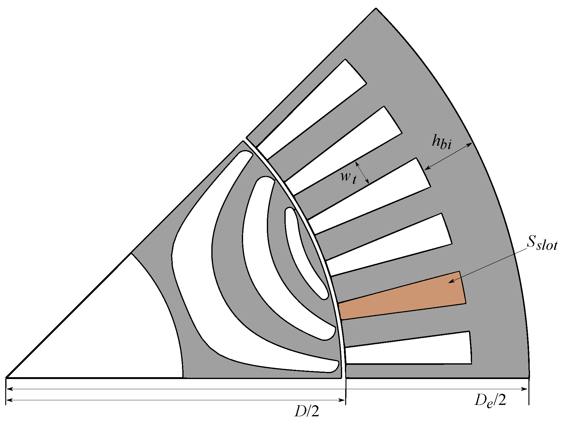
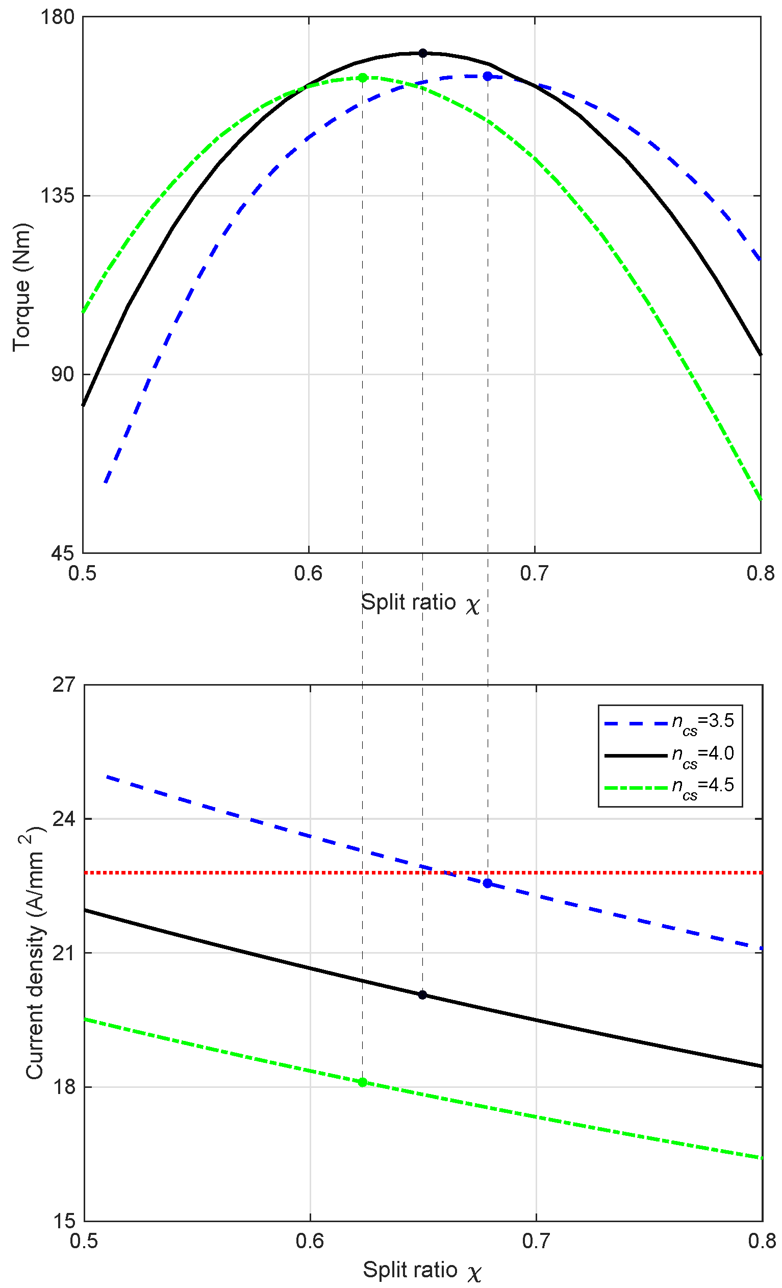
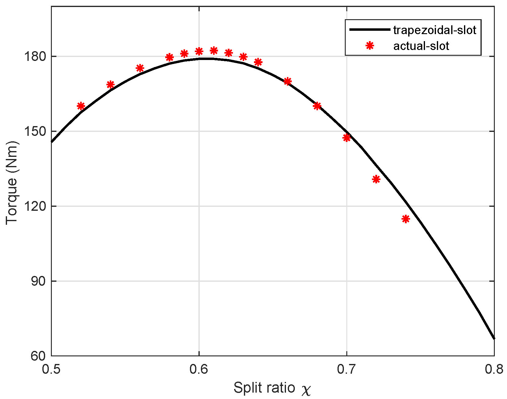
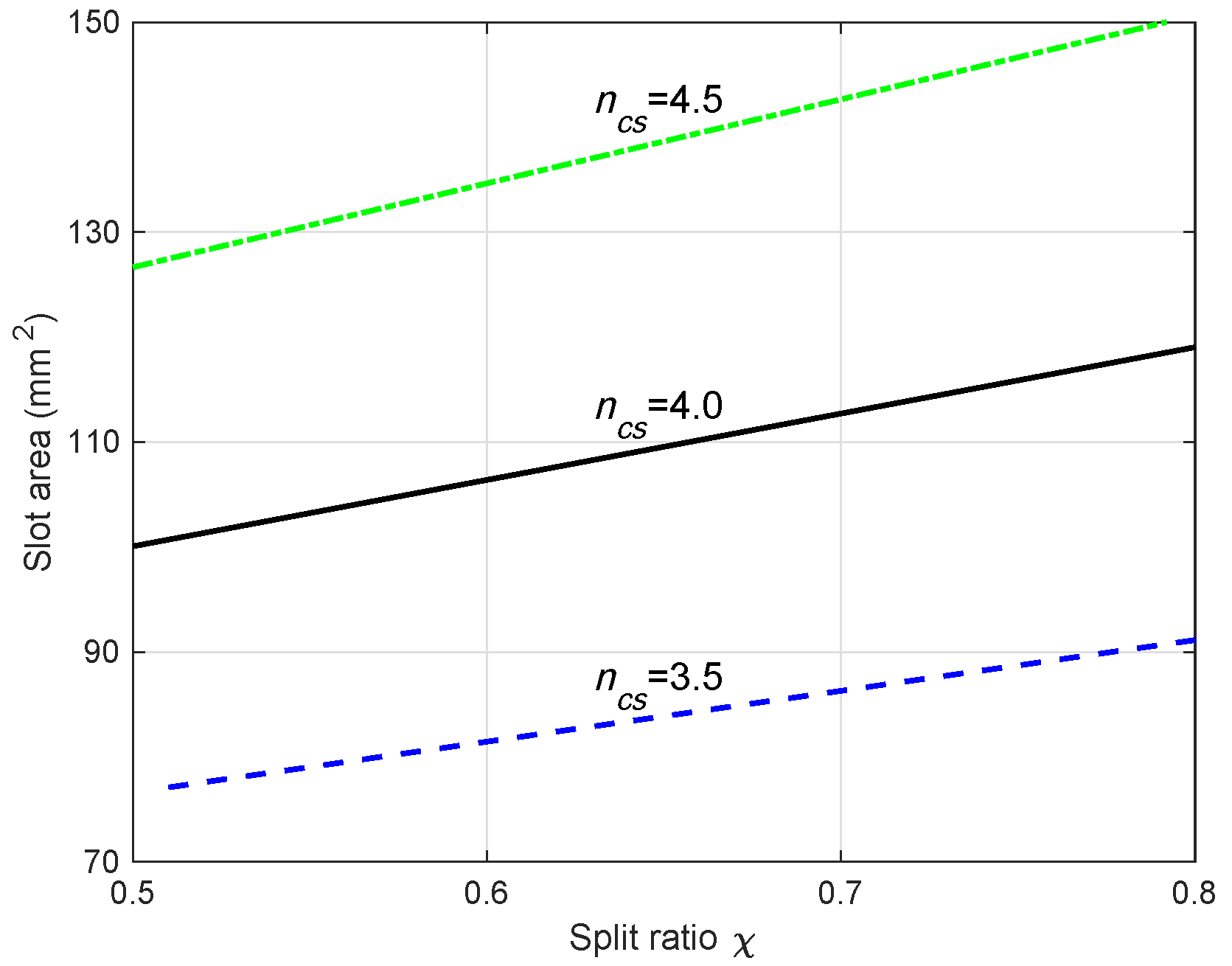
3.1. Split Ratio Optimization

The split ratio ( χ ) is defined as the ratio between the stator’s inner and outer diameters, i.e., χ = D / D e . The torque of an electric machine can be expressed as [35]:
T = π D 2 L s t k 4 K ^ s B ^ g
where L s t k is the stack length, B g ^ is the amplitude of the fundamental harmonic of airgap flux density, and K ^ s is the linear current density, which is represented as:
K ^ s = k w Q s n c s I ^ π D
where k w is the winding factor, Q s is the number of stator slots, n c s is the number of series conductors per slot and I ^ is the phase current peak value. Therefore, the torque equation can be expressed as:
T = 1 4 k w Q s n c s I ^ B g ^ L s t k D e χ
It is observed that the output torque is affected by the split ratio when the stator outer diameter D e is fixed. The focus of this optimization lies in finding the optimal split ratio that achieves the highest torque.
In this analysis, the rotor parameters (flux barrier number, barrier end angles and k a i r ) remain the same. The stator slot is simplified to a trapezoidal shape, as shown in Figure 5. The slot opening is calculated from the slot pitch and stator tooth width, while the slot wedge is neglected.
The flux density ratio β is defined as the ratio of airgap flux density B g ^ and stator teeth flux density B t . Then, the stator teeth width w t is computed as [36]:
w t = B g ^ B t π D Q s = β π D e Q s χ
This equation is also valid for non-linear conditions only if the leakage flux is neglected. The flux passing through the stator’s back iron accounts for half of the main flux in the air gap, which is [36]:
Φ b i = B b i h b i L s t k = 1 2 B g ^ D L s t k p
where B b i is the flux density of the stator’s back iron, p is the number of pole pairs. Combing (4) and (5), the stator’s back iron height h b i is then calculated as:
h b i = 1 2 π Q s p B t B b i w t = 1 2 π Q s p α w t
Here, another parameter α is introduced, which is defined as α = B t / B b i . Considering the knee point of the iron lamination, this ratio is assumed to be constant and equal to 1.16 . Using Equations (4) and (6), the slot area S s l o t is represented as:
S s l o t = π D e 2 4 Q s ( f a β 2 + f b β + f c )
where f a , f b and f c are:
f a = 2 α p α 2 p + 1 χ 2 f b = 2 χ 2 α p + 1 χ f c = 1 χ 2
As a result, S s l o t is simply related to β and χ , since α , D e , Q s and p are supposed to be constant for a given slot–pole combination. The following step is to determine the variation in the slot area S s l o t with split ratio χ , which is based on the assumption of a constant copper loss constraint.
The copper loss can be calculated as:
P c u = 3 2 R I ^ 2 = 3 2 ρ c u L c o n d S s l o t k f i l l ( n c s I ^ ) 2 Q s m
where ρ c u is the copper resistivity, L c o n d is the copper conductor length, k f i l l is the slot fill factor and m is the number of phases. L c o n d includes the stack length and the end-turn length. The end-turn length is technically simplified to 1.6 times of the pole pitch. Then, L c o n d is also related to the split ratio:
L c o n d = L s t k + 1.6 π D 2 p = L s t k + 2.5 D e χ p
From (9), all the parameters are constant, except n c s , χ and S s l o t . Therefore, the variation in the slot area S s l o t with χ can be directly obtained once n c s is given. The relationship of S s l o t , n c s and χ for a 48-slot 8-pole SynRM is plotted in Figure 6. The results show that the slot cross-area increases with the increase in the split ratio χ or n c s .
After determining S s l o t , (7) and (8) are combined to calculate β , which results in:
β = f b f b 2 4 f a f c 2 f a
where:
f c = f c 4 Q s π D e 2 S s l o t
Then, w t and h b i are computed from (4) and (6), respectively. As a consequence, all the parameters to describe the stator’s geometry, i.e., w t , h b i and D, are determined. By using the automatic modeling and simulation procedure, it is easy and fast to repeat these calculations and to investigate the torque behavior for different split ratios. It is noted that the torque is obtained through FEA simulations, and iron saturation is also included. In addition, the current angle is also varied to achieve the maximum average torque values.
The variation of torque with a split ratio is shown in the upper plot of Figure 7, while the corresponding current density is plotted below. Obviously, there exists an optimal split ratio to achieve the highest torque, which is simultaneously affected by n c s . On the other hand, the split ratio is constrained by the current density limit (shown by the dotted line in the lower plot of Figure 7), which is fixed to 22.8 A/mm 2 . This value is reduced from 25 A/mm 2 of the Lexus LS 600h IPM motor due to the increased slot area in the simplified trapezoidal slot. With the decrease in n c s , the current density tends to overcome the limit. Consequently, the calculation of the current density is required during the split ratio optimization process, and the candidates with current densities beyond the limit should be discarded. The maximum torque obtained from Figure 7 is 170.9 Nm, with n c s = 4 and χ = 0.65 .

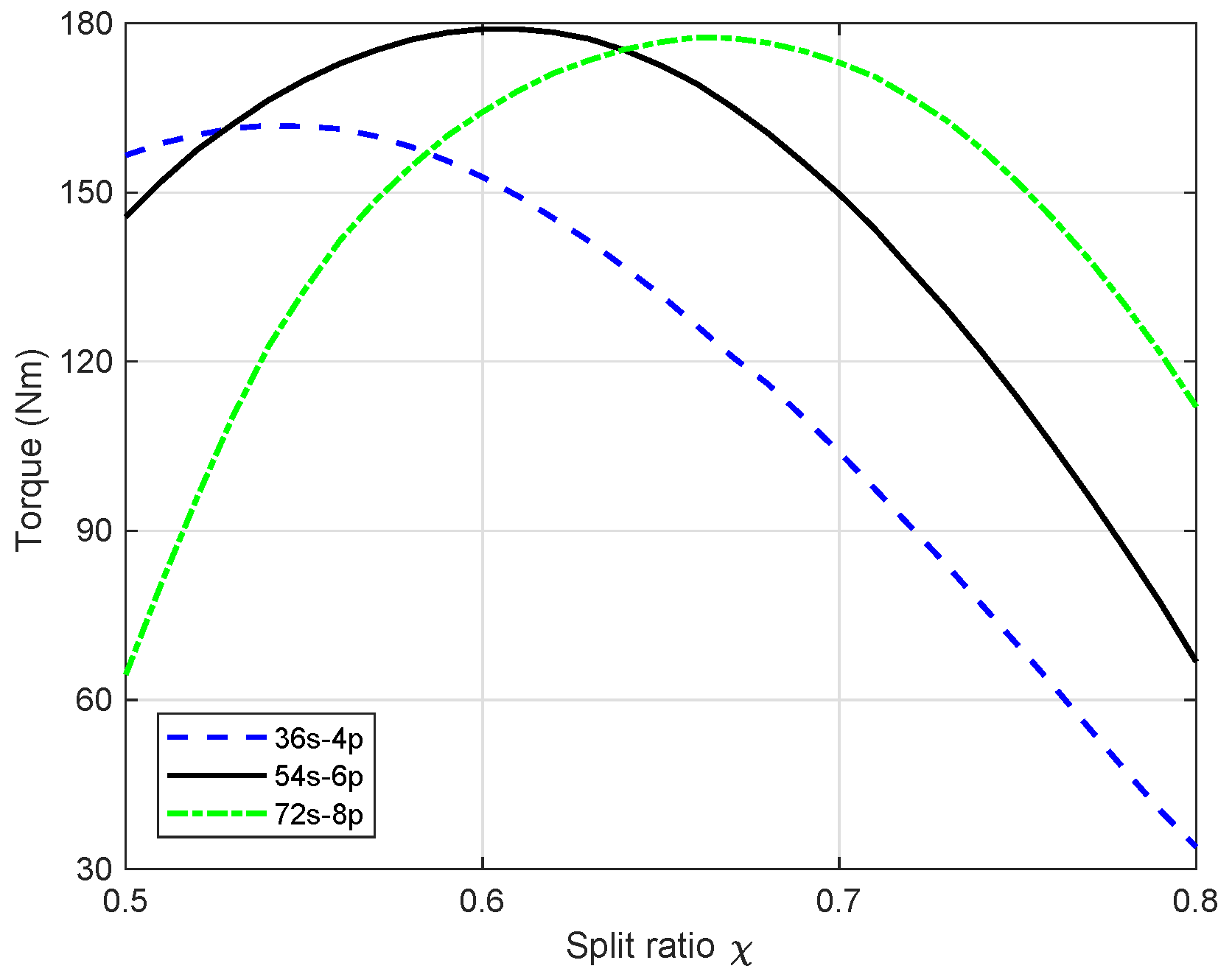
3.2. Slot–Pole Combinations

For the SynRM, it has been revealed that the saliency ratio and torque capability highly depend on the number of pole pairs [35]. Therefore, the slot–pole combination should be reconsidered for maximizing the machine torque. In the following, several combinations are selected and analyzed as listed in Table 2.
For each slot–pole combination, the split ratio optimization is carried out with the aforementioned procedure. After plenty of calculations and FEA simulations, the maximum torque for each slot–pole combination is again reported in Table 2. The optimal n c s and χ are also shown. It is interesting to notice that the optimal split ratio is almost constant corresponding to the same number of pole–pairs. It is increased as the pole–pair number is increased, so as to reduce the tooth length and limit the slot leakage component. A similar conclusion was drawn for the PMaSynRM in [24]. The optimal n c s is found to be inversely proportional to the slot number due to the constant copper loss constraint. In addition, the highest torque is achieved when the pole–pair number is three instead of two, which does not match with the previous finding that the higher pole number the lower torque [37]. In fact, the machine saliency ratio is dramatically reduced as the magnetic saturation increases under overload condition. Therefore, the merit of a thinner stator back iron for higher pole number is becoming more significant.
The results show that the slot–pole combinations with q = 3 exhibit the highest torque capability. The torque behavior versus the split ratio with the optimal n c s of these combinations is plotted in Figure 8. As mentioned, the optimal split ratio increases with the number of pole pairs. The maximum torque of the 54s-6p combination, though not significantly improved from the 72s-8p combination, is the highest. In addition, a low number of pole pairs reduces the operating frequency, leading to low iron losses in the stator. Overall, the 54s-6p combination is chosen as the optimal competitor. As concluded in [35], the saliency ratio of the SynRM is increased as the pole pair number is reduced. Therefore, it is reasonable to have a lower number of pole pairs in a SynRM design compared with an IPM motor.
Since this optimization process is based on a trapezoidal shape slot, the slot opening and wedge are then added to the stator’s geometry (the same values as the Lexus LS 600h IPM motor). The slot area is no longer the same, and β also has to be changed to achieve the same copper loss. Figure 9 shows the torque versus split ratio comparison between the ideal “trapezoidal-shape” slot and the “actual-shape” slot (including wedge and slot opening). As expected, the trend of torque variation is almost the same. Finally, the optimal split ratio is selected to be 0.6 .

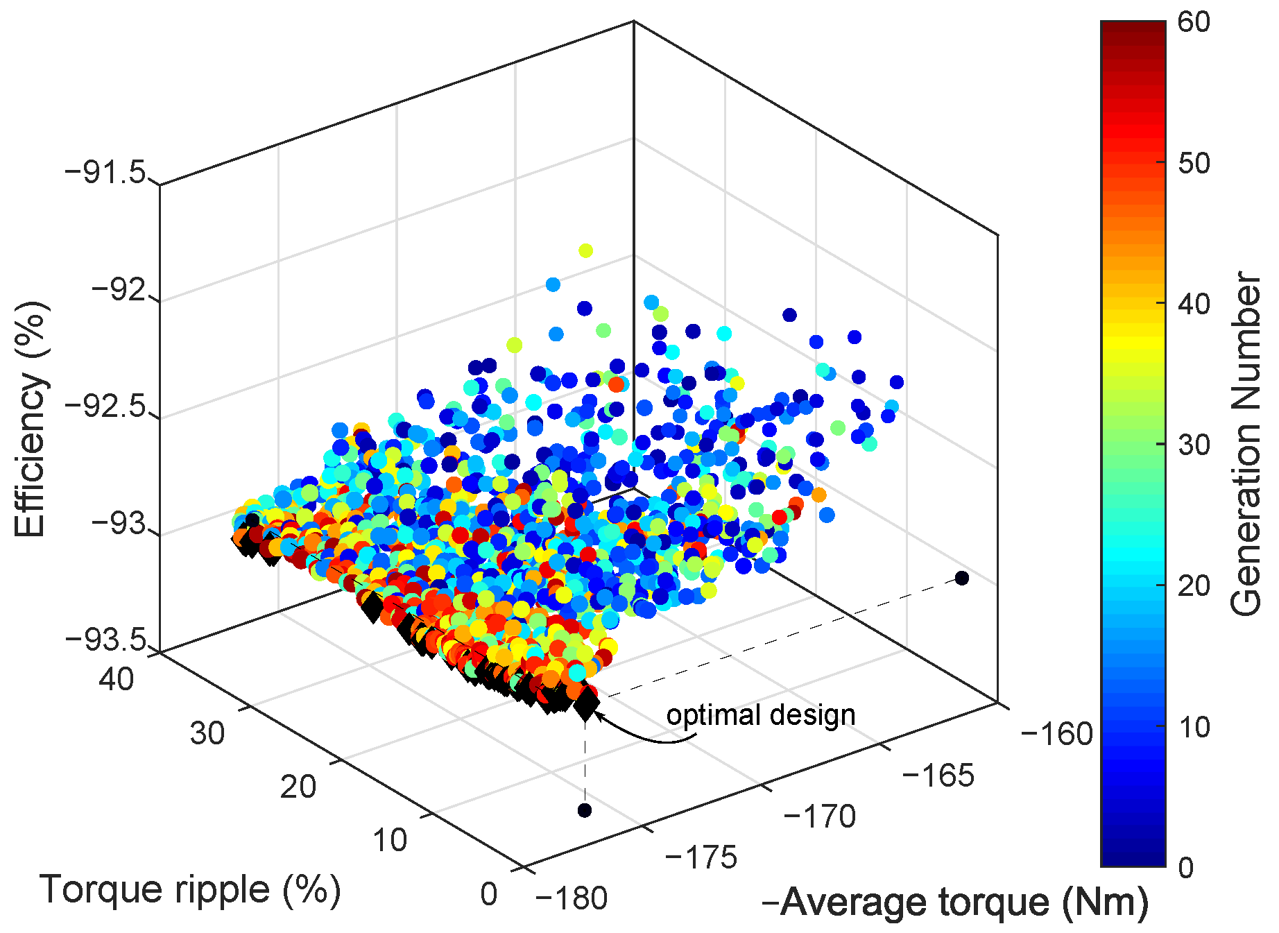
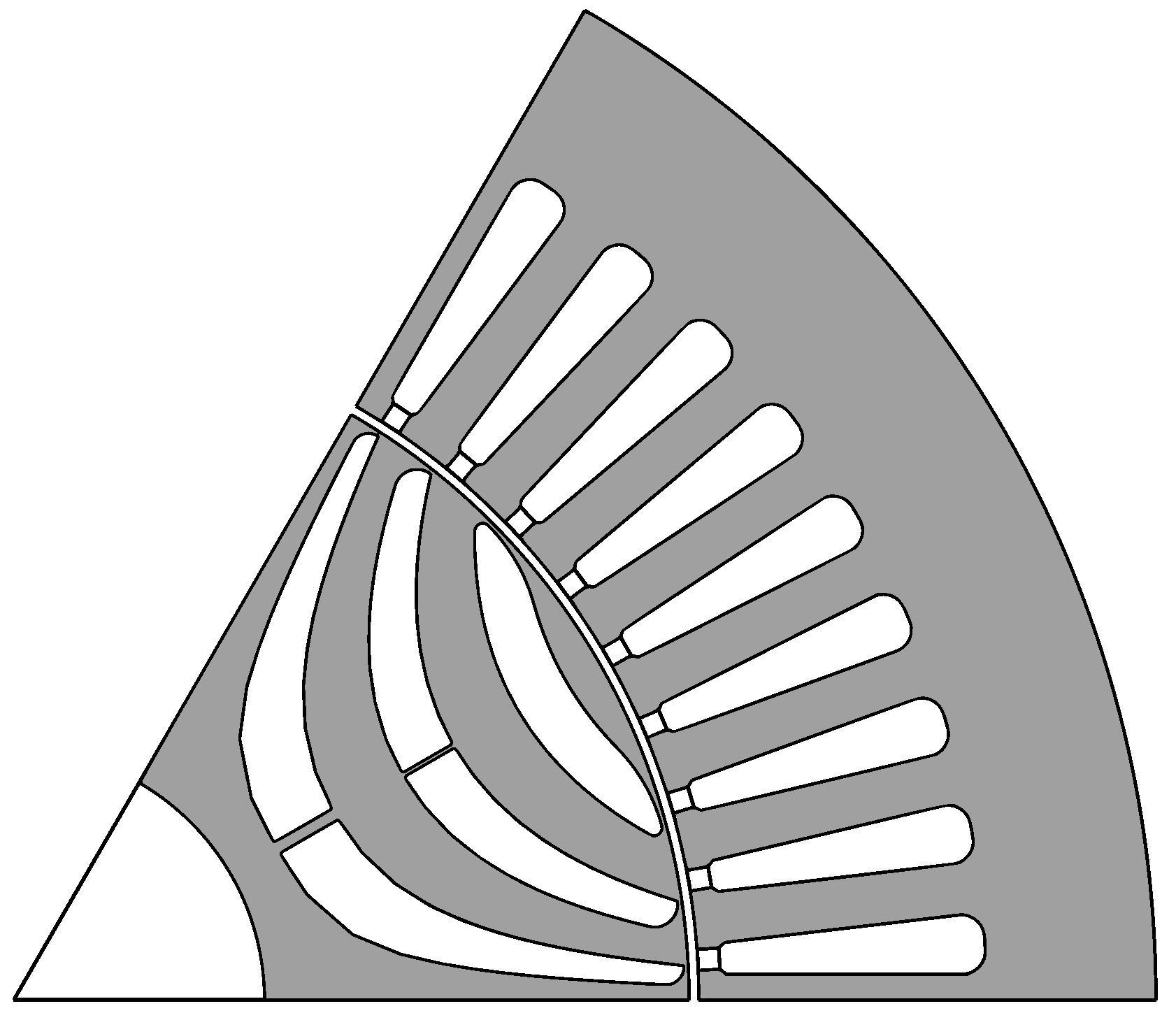
3.3. Rotor Optimization

The rotor optimization process is the same as that described in Section 2. Additionally, efficiency is considered as the third objective, which is obtained from the loss calculation. The copper loss is always the same, since it is kept constant. For simplicity, the iron losses are calculated as follows:
P f e = k m a g g t p s p t G t + k m a g g b i p s p b i G b i
where k m a g g t and k m a g g b i are manufacturing loss increase factors in teeth and back iron, respectively. G t and G b i are the weight of teeth and back iron, respectively, and the specific losses (in teeth and back iron, respectively) are computed as:
p s p = p s p f e B B r e f 2 k h y f f r e f + k e c f f r e f 2
where the specific iron loss of iron lamination p s p f e is the value at reference flux density B r e f and reference frequency f r e f . k h y and k e c are the iron hysteresis loss coefficient and the eddy current loss coefficient. f is the operating frequency, which is 225 Hz at the speed of 4500 rpm. B refers to the maximum flux density of the teeth or back iron, which are obtained from the FEA simulations. The stray loss is considered as 10 % of the total losses ( P c u + P f e ).
As before, the operation point for the optimization is under the maximum current limit and base speed. After optimization, a three-dimensional view of the result is shown in Figure 10. It is interesting that the variation in the torque ripple for the solutions on the Pareto front is more significant than the variations of average torque and efficiency. The optimal point is then selected to achieve the minimum torque ripple, with slight penalization on average torque and efficiency. The projections of this optimal point on each plane are drawn by the black points in Figure 10. The rotor parameter values of the optimal SynRM are shown in Table 3.

3.4. Rotor Structure Enhancement

Since the Lexus LS 600h IPM motor is operated as high as 10,230 rpm [29], the rotor structure analysis of the designed SynRM is conducted. Figure 11a shows the rotor mechanical stress distribution towards centrifugal stress. The maximum stress is noticed to be 1461 MPa, while the Yield stress of the iron lamination is only around 440 MPa. As a result, central bridges in the second and third flux barriers are introduced to reduce the stress concentration on the outer ribs. The thicknesses of these central bridges are optimized to 0.3 mm and 1.0 mm, respectively. As shown in Figure 11b, the maximum stress is then reduced to 354 MPa, which allows a safety factor of 1.24. As a sacrifice, the machine torque is slightly reduced due to the leakage flux path created by the central bridges. The cross-section of the designed SynRM is shown in Figure 1.

4. Performance Comparison among the Motors

According to [29], the maximum torque of the Lexus LS 600h IPM motor within the temperature limit of 150 C for a transient time of 18 s is around 233 Nm. The maximum torque of the optimized SynRM under the same peak current is 178 Nm, which accounts for only 76%. Therefore, the stack length of the designed SynRM is increased in order to meet the same torque and power requirements. As described in the literature [23,24], the PMaSynRM can be obtained directly from the optimized SynRM considering the maximized reluctance torque. For simplicity, the ferrite magnets are fully inserted into the flux barriers of the SynRM rotor, which achieves the same torque as the benchmark IPM motor. The residual magnetic flux density of the ferrite magnet is 0.4 T, and the relative permeability is 1.05. In the following, a detailed performance comparison between the designed motors and the benchmark motor is presented.

4.1. Design Features

Table 4 summarizes the main design characteristics and performance of the designed SynRM/PMaSynRM and the benchmark IPM motor. The active stack length of the SynRM is increased from 135.4 mm to 182 mm, which leads to higher volume and mass. The copper consumed in the SynRM and PMaSynRM is considerably higher than that in the IPM motor, which is attributed to the higher slot area and the longer end winding due to the lower number of pole pairs. The magnet mass of the PMaSynRM is almost doubled from the benchmark IPM motor because of the low residual flux density of the ferrite magnet. It is also noticed that the SynRM requires a deeper rotor to allow for flux flow and a high saliency ratio, and thus, the shaft diameter is lower than the benchmark IPM motor. A shaft diameter of 44 mm is safe and refers to the 2012 Nissan Leaf motor [38].
The unit prices for iron lamination, copper, ferrite and NdFeB magnet are assumed to be 1.4 $/kg [39], 9.8 $/kg [39], 3.2 $/kg [40] and 126.2 $/kg [40], respectively. Both of the SynRM and the PMaSynRM achieves significant cost reduction when compared to the benchmark IPM motor, which are 61.0% and 65.4%, respectively. The rare-earth magnets of the IPM motor contribute over 70 % of the total cost, though they account for only a small fraction of the total mass (less than 5 % ). Given the low cost of the ferrite magnet, the PMaSynRM exhibits the best balance between machine volume and cost.

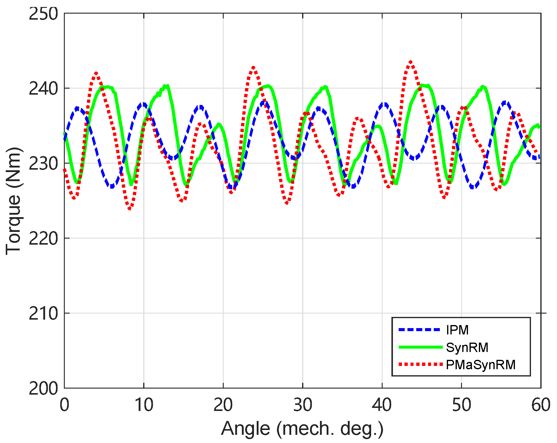
4.2. Torque and Power Capabilities

Generally speaking, the maximum torque and power capabilities of a traction motor are limited by both inverter maximum Volt-Amps rating and machine temperature rise. According to [29], the phase current peak value is set to be 330 A, and the base speed is 4500 rpm with a DC-bus voltage of 650 V. Due to the low power factor of the SynRM, either the peak phase current or DC-bus voltage should be increased, which can be achieved by adjusting the number of series conductors per phase. Since both motors show the same machine performance, the case with higher DC-bus voltage (874 V) but the same peak current is adopted.
As shown in Table 4, the performance of the three motors operated with the peak current at base speed is compared. For a fair comparison, the SynRM and PMaSynRM are designed to exhibit similar torque and power values as the benchmark IPM motor. As expected, the power density and specific power are lower for the designed SynRM. The other problem with the SynRM is the low power factor, which is only 0.58, as reported in Table 4. As a comparison, the power factor of the benchmark IPM motor is 0.78, since it is under the overload condition. The low power factor of the SynRM increases the inverter rating, which explains the increase in the DC-bus voltage. On the contrary, the PMaSynRM achieves almost the similar power density and specific power as the IPM benchmark.
The torque waveforms of the three motors are compared in Figure 12. The average torque of the benchmark IPM motor is very similar to the experimental results in [29], which validates the FEA simulations in this paper. Although the FEA-combined DE algorithm has been adopted for optimization, the torque ripple of the designed SynRM and PMaSynRM are both higher than that of the benchmark IPM motor. The torque ripple is slightly increased from 5.7% to 7.8% by introducing the magnets into the rotor flux barriers. The torque ripple of the PMaSynRM can be further reduced by skewing or introducing minor slits in the rotor surface.

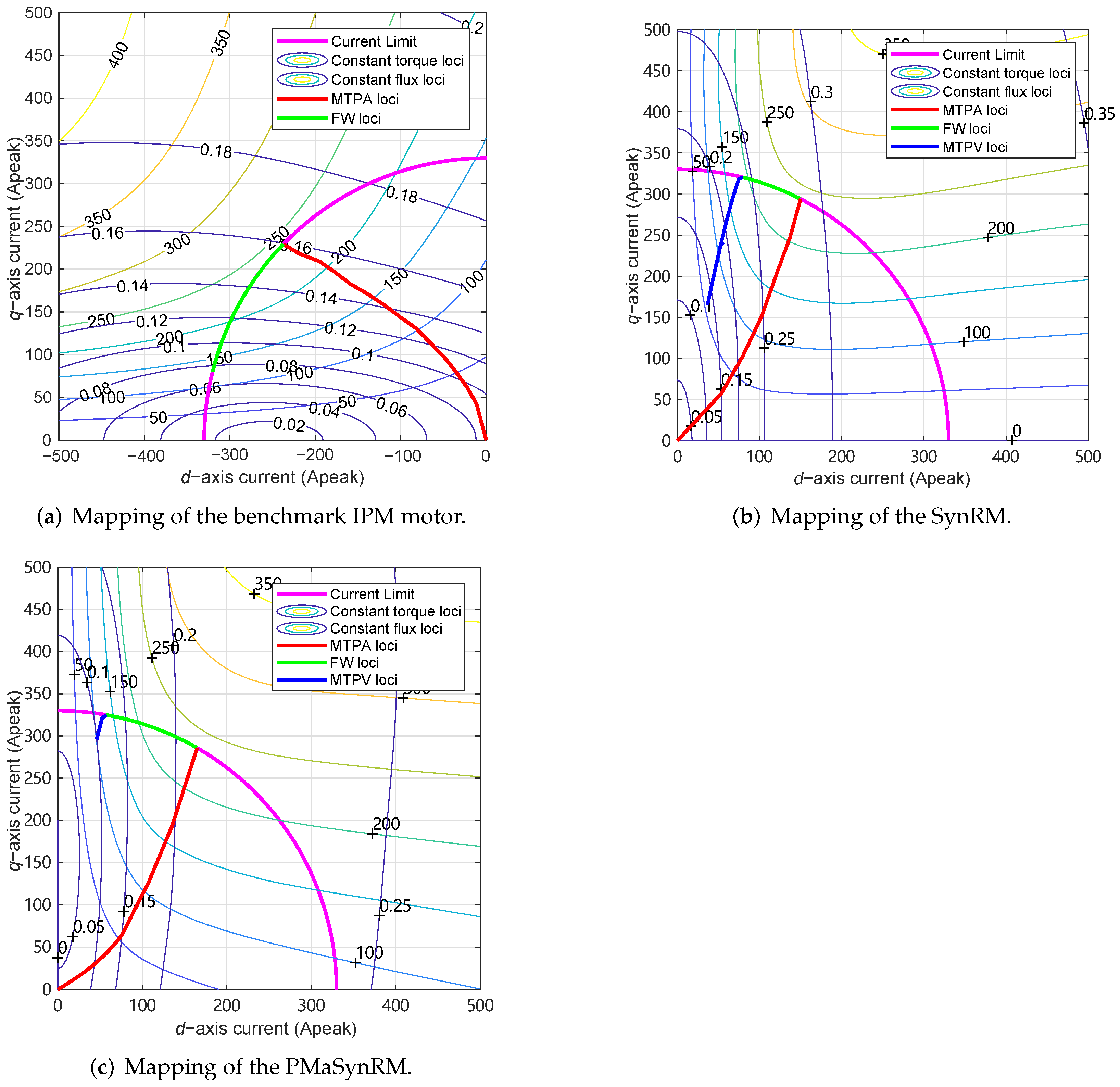
4.3. High-Speed Flux-Weakening Capability
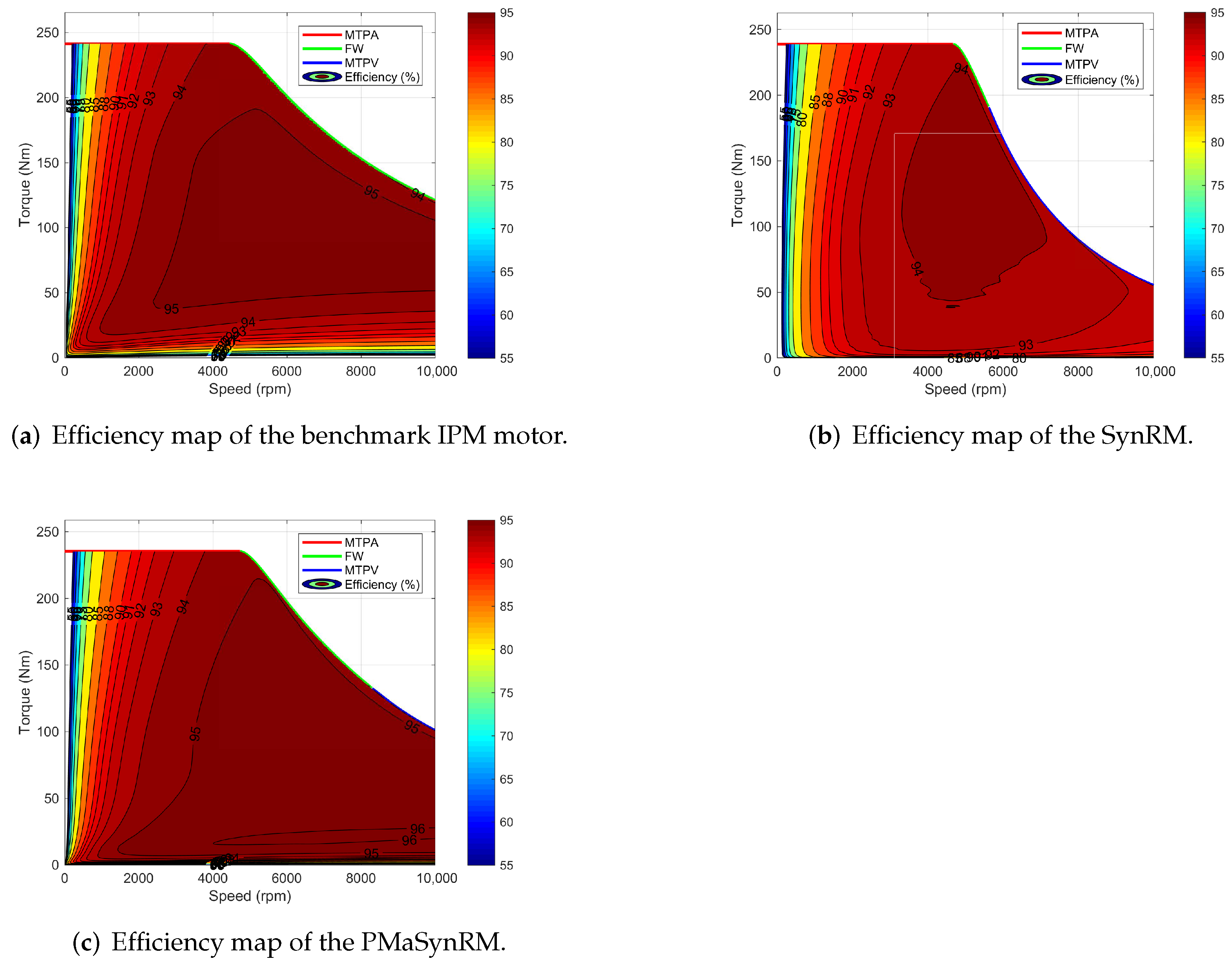
As far as the high-speed flux-weakening (FW) capability is considered, some control methodologies are adopted to achieve the best performance. The optimal current vector trajectory over base speed is achieved by means of FW control and maximum torque-per-voltage (MTPV) control [35]. When the inverter voltage limit is reached, the d-axis current is reduced to weaken the stator flux, i.e., the flux-weakening region. In some cases, for example, when the PM flux linkage is quite low, the current limit circle, the voltage limit ellipse and the MTPV trajectory intersect at a certain speed. Then, the motor moves to the MTPV region at higher speed, in order to maximize the torque under current and voltage limit. In this region, the current amplitude decreases with the increasing speed until reaching the maximum speed. The obtained current vector trajectory is plotted in Figure 13. Within the speed limit of 10,230 rpm, the IPM motor follows only FW operation, while the operations of the SynRM and PMaSynRM cover both FW and MTPV.
The comparison of torque and power capabilities at different speeds of the three motors are plotted in Figure 14. The dashed lines represent the characteristics of the benchmark IPM motor, while the solid lines show the performance of the designed SynRM and the dotted lines refer to the PMaSynRM. The results show that the power of the SynRM drops considerably and the power difference between the SynRM and the IPM motor increases with the speed. More specifically, the benchmark IPM motor delivers more than 120 kW at 10,000 rpm, whereas the SynRM outputs less than 60 kW. Therefore, the SynRMs are not suitable for applications that require a wide constant power speed range (CPSR). The high-speed FW capability of the SynRM can be improved by insetting PMs into flux barriers, as demonstrated by the dotted lines in Figure 14. As concluded in [15], the wider the PM width the better the FW capability.

4.4. Efficiency

The efficiency maps of the three motors are compared in Figure 15. They are obtained by considering copper loss, iron loss and stray loss. The effect of temperature rise on the stator resistance is neglected. From these plots, some useful conclusions can be drawn.
The maximum achievable efficiency of the PMaSynRM is higher than that of the benchmark IPM motor, which is as high as 96 % . In addition, a large portion of the operation region achieves an efficiency above 90 % in the PMaSynRM. It is also worth noticing that the efficiencies of both SynRM and PMaSynRM are higher than that of the IPM counterpart at high-speed low-torque conditions, which is mainly due to the lower flux density of the SynRM and PMaSynRM at this condition.

5. Conclusions

This paper presents a comparative study among a commercial IPM benchmark, a SynRM and a PMaSynRM. Simply starting from rotor replacement, the SynRM rotor is designed by an optimization procedure using FEA-based DE algorithm. It is shown that the achievable torque of the SynRM accounts for 70% of the IPM motor. To fully inspire the potential of the SynRM, the design procedure, which consists of split ratio optimization, slot–pole combination selection, rotor optimization and rotor structure improvement, is followed. A novel method to obtain the optimal split ratio and slot–pole combination with the copper loss constraint, which takes into account the saturation, is proposed. It is noticed that the optimal pole number for the SynRM is six instead of eight for the IPM motor, which implies that the slot–pole combination should be redesigned when machine topologies are changed.
The performance comparison between the optimized SynRM/PMaSynRM and the commercial benchmark is also carried out. The results show that the SynRM achieves the characteristics of significant cost saving ( 61 % cheaper) and low torque ripple ( 5.7 % ). The low power factor reveals increased inverter rating and cost for the SynRM, and the poor FW capability limits its potential for wide CPSR applications. With added ferrite magnet in the rotor flux barriers, the torque density, power factor, efficiency and FW capability are improved. The PMaSynRM enables to achieve a good balance between the cost and the electromagnetic performance. Although the ferrite magnets may experience the risk of demagnetization, it can be well addressed by fine designs with the flux barrier.
This paper clearly shows the gap between well-optimized SynRM/PMaSynRM and a commercial IPM motor. The SynRM can potentially be adopted in cost-effective specialty vehicles, while the competitive performance as the rare-earth PM machines makes the PMaSynRM very promising for passenger cars, buses and heavy-duty trucks.

Author Contributions

Conceptualization, Y.W. and N.B.; methodology, Y.W.; software, Y.W. and N.B.; validation, Y.W. and N.B.; investigation, Y.W. and N.B.; writing—original draft preparation, Y.W.; writing—review and editing, Y.W., N.B. and R.Q.; supervision, N.B. and R.Q.; funding acquisition, Y.W. All authors have read and agreed to the published version of the manuscript.

Funding

This research was funded in part by the National Natural Science Foundation of China (NSFC) under Grant 52107046, in part by the National Natural Science Foundation of Hubei Province under Grant 2021CFB038, and in part by the Fundamental Research Funds for the Central Universities, HUST (2021XXJS009).

Institutional Review Board Statement

Not applicable.

Informed Consent Statement

Not applicable.

Conflicts of Interest

The authors declare no conflict of interest.

References

  1. Chau, K.; Chan, C.; Liu, C. Overview of Permanent-Magnet Brushless Drives for Electric and Hybrid Electric Vehicles. IEEE Trans. Ind. Electron. 2008, 55, 2246–2257. [Google Scholar] [CrossRef] [Green Version]
  2. Vagati, A.; Pellegrino, G.; Guglielmi, P. Comparison between SPM and IPM motor drives for EV application. In Proceedings of the 2010 International Conference on Electrical Machines (ICEM), Rome, Italy, 6–8 September 2010; pp. 1–6. [Google Scholar] [CrossRef]
  3. EL-Refaie, A.M.; Alexander, J.P.; Galioto, S.; Reddy, P.B.; Huh, K.K.; de Bock, P.; Shen, X. Advanced High-Power-Density Interior Permanent Magnet Motor for Traction Applications. IEEE Trans. Ind. Appl. 2014, 50, 3235–3248. [Google Scholar] [CrossRef]
  4. Zhu, Z.Q.; Chu, W.Q.; Guan, Y. Quantitative comparison of electromagnetic performance of electrical machines for HEVs/EVs. CES Trans. Electr. Mach. Syst. 2017, 1, 37–47. [Google Scholar] [CrossRef]
  5. Dorrell, D.G.; Knight, A.M.; Popescu, M.; Evans, L.; Staton, D.A. Comparison of different motor design drives for hybrid electric vehicles. In Proceedings of the 2010 IEEE Energy Conversion Congress and Exposition, Atlanta, GA, USA, 12–16 September 2010; pp. 3352–3359. [Google Scholar] [CrossRef]
  6. Zhu, Z.Q.; Howe, D. Electrical Machines and Drives for Electric, Hybrid, and Fuel Cell Vehicles. Proc. IEEE 2007, 95, 746–765. [Google Scholar] [CrossRef]
  7. Pellegrino, G.; Vagati, A.; Boazzo, B.; Guglielmi, P. Comparison of Induction and PM Synchronous Motor Drives for EV Application Including Design Examples. IEEE Trans. Ind. Appl. 2012, 48, 2322–2332. [Google Scholar] [CrossRef] [Green Version]
  8. Chiba, A.; Takano, Y.; Takeno, M.; Imakawa, T.; Hoshi, N.; Takemoto, M.; Ogasawara, S. Torque Density and Efficiency Improvements of a Switched Reluctance Motor Without Rare-Earth Material for Hybrid Vehicles. IEEE Trans. Ind. Appl. 2011, 47, 1240–1246. [Google Scholar] [CrossRef]
  9. Kiyota, K.; Kakishima, T.; Chiba, A. Comparison of Test Result and Design Stage Prediction of Switched Reluctance Motor Competitive with 60-kW Rare-Earth PM Motor. IEEE Trans. Ind. Electron. 2014, 61, 5712–5721. [Google Scholar] [CrossRef]
  10. Lan, Y.; Benomar, Y.; Deepak, K.; Aksoz, A.; Baghdadi, M.E.; Bostanci, E.; Hegazy, O. Switched Reluctance Motors and Drive Systems for Electric Vehicle Powertrains: State of the Art Analysis and Future Trends. Energies 2021, 14, 2079. [Google Scholar] [CrossRef]
  11. Kiyota, K.; Kakishima, T.; Chiba, A.; Rahman, M.A. Cylindrical Rotor Design for Acoustic Noise and Windage Loss Reduction in Switched Reluctance Motor for HEV Applications. IEEE Trans. Ind. Appl. 2016, 52, 154–162. [Google Scholar] [CrossRef]
  12. Vagati, A.; Franceschini, G.; Marongiu, I.; Troglia, G. Design criteria of high performance synchronous reluctance motors. In Proceedings of the Conference Record of the 1992 IEEE Industry Applications Society Annual Meeting, Houston, TX, USA, 4–9 October 1992; Volume 1, pp. 66–73. [Google Scholar] [CrossRef]
  13. Lipo, T.A. Synchronous Reluctance Machines-A Viable Alternative for AC Drives? Electr. Mach. Power Syst. 1991, 19, 659–671. [Google Scholar] [CrossRef]
  14. Bianchi, N.; Bolognani, S.; Bon, D.; Pre, M.D. Rotor Flux-Barrier Design for Torque Ripple Reduction in Synchronous Reluctance and PM-Assisted Synchronous Reluctance Motors. IEEE Trans. Ind. Appl. 2009, 45, 921–928. [Google Scholar] [CrossRef]
  15. Wang, Y.; Bacco, G.; Bianchi, N. Geometry Analysis and Optimization of PM-Assisted Reluctance Motors. IEEE Trans. Ind. Appl. 2017, 53, 4338–4347. [Google Scholar] [CrossRef]
  16. Gedara, I.P.A.H. Design Optimization and Performance Improvement of Synchronous Reluctance Machines. Ph.D. Thesis, University of Manitoba, Winnipeg, MB, Canada, 2019. [Google Scholar]
  17. Pellegrino, G.; Cupertino, F.; Gerada, C. Automatic Design of Synchronous Reluctance Motors Focusing on Barrier Shape Optimization. IEEE Trans. Ind. Appl. 2015, 51, 1465–1474. [Google Scholar] [CrossRef]
  18. Mirazimi, M.S.; Kiyoumarsi, A. Magnetic Field Analysis of SynRel and PMASynRel Machines with Hyperbolic Flux Barriers Using Conformal Mapping. IEEE Trans. Transp. Electrif. 2020, 6, 52–61. [Google Scholar] [CrossRef]
  19. Alani, M.; Degano, M.; Bianchi, N.; Mahmoud, H.; Gerada, C. Analysis and Design of Dual-Rotor Synchronous Reluctance Machine. IEEE J. Emerg. Sel. Top. Power Electron. 2021, 9, 4376–4383. [Google Scholar] [CrossRef]
  20. Boldea, I.; Tutelea, L.; Pitic, C.I. PM-assisted reluctance synchronous motor/generator (PM-RSM) for mild hybrid vehicles: Electromagnetic design. IEEE Trans. Ind. Appl. 2004, 40, 492–498. [Google Scholar] [CrossRef]
  21. Jahns, T. Getting Rare-Earth Magnets Out of EV Traction Machines: A review of the many approaches being pursued to minimize or eliminate rare-earth magnets from future EV drivetrains. IEEE Electrif. Mag. 2017, 5, 6–18. [Google Scholar] [CrossRef]
  22. Tahanian, H.; Aliahmadi, M.; Faiz, J. Ferrite Permanent Magnets in Electrical Machines: Opportunities and Challenges of a Non-Rare-Earth Alternative. IEEE Trans. Magn. 2020, 56, 1–20. [Google Scholar] [CrossRef]
  23. Armando, E.; Guglielmi, P.; Pastorelli, M.; Pellegrino, G.; Vagati, A. Performance of IPM-PMASR Motors with Ferrite Injection for Home Appliance Washing Machine. In Proceedings of the 2008 IEEE Industry Applications Society Annual Meeting, Edmonton, AB, Canada, 5–9 October 2008; pp. 1–6. [Google Scholar] [CrossRef]
  24. Vagati, A.; Boazzo, B.; Guglielmi, P.; Pellegrino, G. Ferrite assisted synchronous reluctance machines: A general approach. In Proceedings of the 2012 XXth International Conference on Electrical Machines, Marseille, France, 2–5 September 2012; pp. 1315–1321. [Google Scholar]
  25. Guan, Y.; Zhu, Z.Q.; Afinowi, I.A.A.; Mipo, J.C.; Farah, P. Design of synchronous reluctance and permanent magnet synchronous reluctance machines for electric vehicle application. In Proceedings of the 2014 17th International Conference on Electrical Machines and Systems (ICEMS), Hangzhou, China, 22–25 October 2014; pp. 1853–1859. [Google Scholar] [CrossRef]
  26. Reddy, P.B.; El-Refaie, A.M.; Galioto, S.; Alexander, J.P. Design of Synchronous Reluctance Motor Utilizing Dual-Phase Material for Traction Applications. IEEE Trans. Ind. Appl. 2017, 53, 1948–1957. [Google Scholar] [CrossRef]
  27. Grace, K.; Galioto, S.; Bodla, K.; El-Refaie, A.M. Design and Testing of a Carbon-Fiber-Wrapped Synchronous Reluctance Traction Motor. IEEE Trans. Ind. Appl. 2018, 54, 4207–4217. [Google Scholar] [CrossRef]
  28. Li, Y.; Yang, H.; Lin, H.; Fang, S.; Wang, W. A Novel Magnet-Axis-Shifted Hybrid Permanent Magnet Machine for Electric Vehicle Applications. Energies 2019, 12, 641. [Google Scholar] [CrossRef] [Green Version]
  29. Burress, T.A.; Coomer, C.L.; Campbell, S.L.; Wereszczak, A.A.; Cunningham, J.P.; Marlino, L.D.; Seiber, L.E.; Lin, H.T. Evaluation of the 2008 Lexus LS 600h Hybrid Synergy Drive System; Oak Ridge National Lab. (ORNL): Oak Ridge, TN, USA, 2009. [Google Scholar]
  30. Storn, R.; Price, K. Differential Evolution—A Simple and Efficient Adaptive Scheme for Global Optimization over Continuous Spaces; International Computer Science Institute: Berkeley, CA, USA, 1995. [Google Scholar]
  31. Chakraborty, U.K. Advances in Differential Evolution; Springer: Berlin, Germany, 2008. [Google Scholar]
  32. Prado, R.S.; Silva, R.C.P.; Guimarães, F.G.; Neto, O.M. Using differential evolution for combinatorial optimization: A general approach. In Proceedings of the 2010 IEEE International Conference on Systems, Man and Cybernetics, Istanbul, Turkey, 10–13 October 2010; pp. 11–18. [Google Scholar] [CrossRef]
  33. Sizov, G.Y.; Zhang, P.; Ionel, D.M.; Demerdash, N.A.O.; Rosu, M. Automated Multi-Objective Design Optimization of PM AC Machines Using Computationally Efficient FEA and Differential Evolution. IEEE Trans. Ind. Appl. 2013, 49, 2086–2096. [Google Scholar] [CrossRef]
  34. Zarko, D.; Ban, D.; Lipo, T.A. Analytical Solution for Cogging Torque in Surface Permanent-Magnet Motors Using Conformal Mapping. IEEE Trans. Magn. 2008, 44, 52–65. [Google Scholar] [CrossRef]
  35. Bianchi, N.; Jahns, T.M. Design, analysis, and control of interior PM synchronous machines. In Proceedings of the IEEE Industry Applications Society Annual Meeting, CLEUP, Seattle, WA, USA, 3 October 2004. [Google Scholar]
  36. Bianchi, N.; Bolognani, S.; Grezzani, G. PM Motors for Very High Dynamic Applications. In Proceedings of the 2005 IEEE 36th Power Electronics Specialists Conference, Dresden, Germany, 16 June 2005; pp. 1332–1338. [Google Scholar] [CrossRef]
  37. Wang, K.; Zhu, Z.Q.; Ombach, G.; Koch, M.; Zhang, S.; Xu, J. Optimal slot/pole and flux-barrier layer number combinations for synchronous reluctance machines. In Proceedings of the 2013 Eighth International Conference and Exhibition on Ecological Vehicles and Renewable Energies (EVER), Monte Carlo, Monaco, 27–30 March 2013; pp. 1–8. [Google Scholar] [CrossRef]
  38. Liang, J.; Jiang, J.W.; Bilgin, B.; Emadi, A. Shaft Design for Electric Traction Motors. IEEE Trans. Transp. Electrif. 2018, 4, 720–731. [Google Scholar] [CrossRef]
  39. The World Centre for Industrial Metals Pricing… Hedging… Trading. Available online: https://www.lme.com/en/ (accessed on 1 January 2022).
  40. Available online: https://www.kedemagnetics.com/kede-about.html (accessed on 1 January 2022).
Figure 1. One-pole cross-section of a 54s-6p SynRM.
Energies 15 02711 g001
Figure 2. Optimization procedure using FEA and DE algorithm.
Energies 15 02711 g002
Figure 3. Parameters definition of a SynRM rotor with three barriers per pole.
Energies 15 02711 g003
Figure 4. Optimization results for SynRM solutions with three barriers and four barriers per pole, respectively: (a) Three barriers per pole rotor; (b) Four barriers per pole rotor.
Energies 15 02711 g004
Figure 5. Simplified drawing of the SynRM with “trapezoidal-shape” slot.
Energies 15 02711 g005
Figure 6. Variation in slot cross-section area with split ratio for a 48-slot 8-pole SynRM ( n c s is assumed to be 3.5, 4.0 and 4.5, respectively).
Energies 15 02711 g006
Figure 7. Variations in torque and current density with split ratio for a 48-slot 8-pole SynRM ( n c s is assumed to be 3.5, 4.0 and 4.5, respectively).
Energies 15 02711 g007
Figure 8. Variations in torque with split ratio for the SynRMs with different slot–pole combinations and q = 3 .
Energies 15 02711 g008
Figure 9. Torque versus split ratio comparison between the SynRMs with simplified “trapezoidal-shape” slot and “actual-shape” slot.
Energies 15 02711 g009
Figure 10. Optimization results of the 54s-6p SynRMs.
Energies 15 02711 g010
Figure 11. Mechanical stress distribution of the designed SynRM rotors at the speed of 10,230 rpmL: (a) The optimized SynRM rotor; (b) The optimized SynRM rotor with central bridges.
Energies 15 02711 g011
Figure 12. Torque waveform comparison of the three motors under the maximum current (the benchmark IPM motor: dashed lines; the SynRM: solid lines; the PMaSynRM: dotted lines).
Energies 15 02711 g012
Figure 13. Comparison of the current vector trajectory of the three motors.
Energies 15 02711 g013
Figure 14. Comparison of torque and power variations versus speed of the three motors (the benchmark IPM motor: dashed lines; the SynRM: solid lines; the PMaSynRM: dotted lines): (a) Torque versus speed; (b) Power versus speed.
Energies 15 02711 g014
Figure 15. Comparison of the efficiency maps of the three motors.
Energies 15 02711 g015
Table 1. Main Dimensions of the Lexus LS 600h IPM Motor.
Design ParametersSymbolValueUnit
Number of stator slots Q s 48
Number of poles 2 p 8
Stator outer diameter D e 200mm
Stator inner diameterD130.86mm
Shaft diameter D s h 53mm
Active stack length L s t k 135.4mm
Airgap thicknessg0.89mm
Table 2. The Selected Slot–Pole Combinations with Their Optimal Split Ratio and Torque.
Q s pqWinding Factor n cs opt χ opt T max
24220.9667.50.54154.5
36230.9605.00.54161.9
48240.9583.50.56158.9
36320.9665.00.61171.5
54330.9603.50.60179.0
72340.9582.50.62176.3
48420.9664.00.65170.9
72430.9602.50.66177.5
96440.9582.00.65176.8
Table 3. Rotor Parameter Values of the Optimal SynRM Design.
Parameters k air θ b 1 θ b 2 θ b 3
Values 0.44 15.0 21.5 27.2
Table 4. Main Design Characteristics and Performance Comparison of the Three Motors.
Benchmark IPM MotorSynRMPMaSynRMUnit
Number of stator slots485454
Number of poles866
Stator outer diameter200200200mm
Stator inner diameter130.86120120mm
Airgap thickness0.890.890.89mm
Shaft diameter534444mm
Active stack length135.4182135.4mm
Active volume4.255.724.25L
Stator core mass15.1521.0915.69kg
Stator core cost21.229.522.0$
Copper mass3.595.404.51kg
Copper cost35.252.944.2$
Rotor mass9.607.975.96kg
Rotor cost13.411.28.3$
Magnet mass1.3502.68kg
Magnet cost170.408.6$
Total mass29.6934.4628.84kg
Total material cost240.293.683.1$
DC-bus voltage650874650V
Current330330330A p e a k
Maximum torque233.4234.1231.7Nm
Maximum power110.0110.3109.2kW
Power density25.919.325.2kW/L
Specific power3.73.23.8kW/kg
Power factor0.780.580.76
Publisher’s Note: MDPI stays neutral with regard to jurisdictional claims in published maps and institutional affiliations.

