Abstract
The safety of high-level radioactive waste disposal has been studied across the world considering mined geologic repositories. Here, we introduce large-diameter, deep borehole disposal as one of the potential solutions for small volumes of long-lived intermediate-level waste (ILW). The short- and long-term stability of deep disposal boreholes is critical for environmental safety and public health. In this paper, we first use a recently revisited extensional strain criterion for fracture initiation and apply analytical solutions of a two-dimensional stress model to predict the fracturing region around a 2 km deep and 0.7 m diameter disposal borehole. Analytical solutions of fracture initiation are compared with results from the numerical simulator FRACOD, while the latter model also predicts dynamic effects such as fracture propagation. Both analytical and numerical methods predicted similar fracture initiation characteristics around the minor horizontal compressive stress springline, consistent with literature data. Numerical results showed deeper fracturing zones than those predicted by analytical solutions, mainly because the analytical predictions provide static snapshots under specific given conditions, while the numerical model calculates additional dynamic effects of fracture propagation. Including stress dynamics is shown to further weaken the rock around the borehole. At the bottom plane of the borehole, three-dimensional numerical simulations showed the development of fracturing zones around the major horizontal compressive stress springline. Borehole stability analyses are essential to plan the safe operation of drilling operations while also giving insights as to what borehole depths are more prone to fracturing and hence potentially less suitable as a waste disposal zone.
1. Introduction
Radioactive materials are used in power generation, to produce radiopharmaceuticals used in medical diagnostics and treatments, and in industrial applications and scientific research. The waste from these applications is also radioactive, varying from low-level (LLW) through intermediate-level (ILW) to high-level (HLW) [1]. Securing the safety of radioactive waste disposal is critical for public health. There has been considerable research on geological disposal of intermediate-level and high-level radioactive waste in conventional mined geologic repositories [2], including large-scale demonstration tests in numerous underground research laboratories (URLs) [3,4].
The main technology for long-term disposal of high-level radioactive waste considers underground tunnels or caverns [2,5]. The first operational geological disposal facility for spent nuclear fuel from commercial power plants will be the ONKALO disposal facility in crystalline rock in Finland [6]. An alternative concept that is receiving considerable attention for disposal of small volumes of long-lived ILW, separated plutonium wastes and some very high specific activity fission-product wastes, and HLW, considers deep boreholes drilled from ground surface [7,8,9]. The concept of deep borehole disposal (DBD) has been studied in several countries. For instance, in Sweden, DBD has received considerable attention since the late 1980s [10,11,12,13]. DBD has also been examined in the US as an option for disposal of high-level waste and high-activity Cs and Sr sources in small capsules [14,15,16], in the United Kingdom [17,18], Germany [19], South Korea [20,21,22], and Russia [23].
Radioactive waste disposal studies typically cover various aspects, such as geological conditions of the sites, durability of the engineered barriers including waste containers, post-closure safety assessments, and, in the case of borehole disposal, geomechanical stability of the boreholes. Beswick et al. [24] investigated the engineering challenges related to DBD. Recently, Mallants et al. [9] summarized the state of the science and technology of borehole disposal. Unlike conventional geologic disposal facilities, there has not been any full-scale field demonstration of the DBD concept to date. The need for field tests was advocated by Freeze et al. [25], where the waste emplacement testing could be undertaken in a phased manner, initially using a shallow borehole with surrogate canisters to test surface handling, emplacement, and safety protocols before moving to a full-scale field-testing in a deeper borehole. An important technological challenge in crystalline rock is the drilling of a large-diameter, deep borehole as part of the full-scale field test. Several bottom-hole diameters and depths have been considered, from 0.91 m diameter and 3 km deep [26], to 0.43 m diameter and 5 km depth [27], and ~0.7 m diameter and depths between 1 km and 3 km [28].
Drilling large-diameter boreholes at larger depths has its own challenges, particularly in brittle material such as crystalline and sedimentary rock [24,26]. For instance, borehole instabilities often occur during and after drilling as a result of crack initiation and propagation [29,30]. Borehole breakouts may form at the borehole wall in the direction of the minimum principal horizontal stress, whereas tensile fractures may form in the direction of the maximum principal horizontal stress. Especially in hard rocks such as granite, explicit fracturing occurs with the size of the borehole breakout region, or the depth of the excavation damaged zone, increasing with increasing in situ stresses and borehole size [31]. Therefore, understanding borehole stability, its occurrence, and size of failure regions is critically important for deep, large-diameter boreholes for the disposal of radioactive waste. In addition to complicating the drilling operation, borehole failures may also impact the suitable depth available for waste emplacement and may create local temporal fracture networks that require specialized sealing materials to restrict radionuclide migration along the fractured borehole wall [32].
Borehole stability has been the subject of many studies [31,33,34,35,36,37,38]. Bradley [33] investigated various borehole failures with analytical solutions for stress distribution around the borehole involving a tensile stress criterion and a compressive stress criterion; their study addressed inward plastic deformation of rock causing hole size reduction, borehole breakouts causing hole enlargement, and tensile fracturing causing loss of drilling fluid. Haimson [34] reviewed different borehole breakout failure mechanisms observed from laboratory research. Most breakouts have a dog-ear shape, but quartz-rich sandstones develop tabular slot-shaped breakouts that maintain a constant and very narrow width over an extensive length, resulting in a fracture-like appearance.
Regarding the size of the failure region, the interest is commonly in its depth and the span angle, or angular span, on the borehole surface. Theoretically, the span angle of the failure region on the borehole surface from a two-dimensional solution does not depend on the hole size (radius) since the stresses for the failure are evaluated on the surface and the hole size does not appear in the evaluation. However, Lin et al. [31] found experimentally that the angular span increases with increasing hole size for a given horizontal stress ratio. There may be two reasons for this discrepancy: (1) experiments use samples of finite size while the theoretical prediction applies to an infinite domain, and (2) the theoretical prediction is a static response for a given loading while the experiments experience progressive deformation from the start of loading to the final loading. Based on a simple expression, the depth of the failure region is more difficult to predict analytically than the span angle.
Most borehole stability studies employ two-dimensional models due to their simplicity for investigating the breakout or failure around the borehole surface. Liu et al. [39] proposed a coupled numerical approach to simultaneously investigate effects of drilling mud pressure, overburden pressure, horizontal in situ stresses, temperature changes, and pore pressure on the stress field around the bottom of borehole. The drilling mud pressure has a significant influence: increasing the mud pressure would make breaking the rock at the borehole bottom more difficult. Tensile stresses exist beneath the bottom of the borehole due to a pore pressure gradient. Ito et al. [36] numerically investigated the three-dimensional stress field and associated breakout around the borehole, including the bottom of the borehole. They found that on cross-sectional planes around the bottom of the borehole, failure along the maximum horizontal compression springline is larger than that along the minimum horizontal compression springline. By using a very comprehensive constitutive model, Shalev et al. [38] predicted numerically that borehole breakouts around the bottom of the borehole have their greatest extent along the maximum horizontal compression springline.
Deep boreholes drilled to 1000–2000 m depth into crystalline rocks in Australia have been reported to have experienced borehole instabilities [29]. This is believed to be caused by high pressure (i.e., high horizontal stresses) from tectonic movement. Large diameter boreholes such as the one considered here (bottom hole diameter of approximately 0.7 m) are particularly susceptible for borehole breakouts due to scale effects [40].
In anticipation of potential future needs for drilling such deep boreholes for radioactive waste disposal in Australia and elsewhere, we first employed the extensional strain criterion for fracture initiation from Barton and Shen [41] together with the two-dimensional analytical solution of stresses around a vertical borehole to predict the fracturing region under in situ stresses. The fracturing region from the Mohr-Coulomb shearing criterion is also investigated to compare with that from the extensional strain criterion. Next, 2D and 3D numerical codes were employed to (1) verify the results obtained with the 2D-analytical solution, and (2) to simulate 3D fracture dynamics including initiation and propagation around the bottom of a borehole that were not possible with the analytical solutions. In this study, crystalline rock has been considered as it is more susceptible to borehole breakouts compared to sedimentary rock because the crystalline rock often exhibits high strength and undergoes brittle failure, whereas the sedimentary rock is often soft and the failure could be in the form of large deformations [38].
2. Two-Dimensional Analytical Stress Solutions for Prediction of Fracturing Zones
For predictions of the stress state along most part of deep vertical boreholes without asymmetrical defects, effects of top and bottom of the borehole are very small and stresses and deformation on all the cross-sectional planes are independent from the position of the planes; therefore, 2D plane-strain solutions are valid [42]. Around the bottom of the borehole, however, the stresses and deformation on a cross-sectional plane depend on the position of the plane and 3D solutions should be sought [42]. In this first step, the 2D analytical solution of stresses and an extensional strain criterion for fracture initiation are used to predict the regions along a 2 km deep and 0.7 m bottom-hole diameter borehole in which fractures are most likely to be initiated.
2.1. Stresses around a Borehole under Biaxial Compressions and Internal Pressure
Let O-x-y be a 2D Cartesian coordinate system and O-r-θ a cylindrical coordinate system associated with the O-x-y system in the horizontal cross-sectional plane of the borehole (Figure 1). The angular θ is positive measured anticlockwise from the x-axis. We consider the stress states around a circular hole, centred at the origin of the coordinate systems and with radius R, in an infinite 2D domain under far field biaxial compression P1 in the x-direction and P2 in the y-direction. The borehole surface is under internal pressure P0. These stresses all affect fracture behaviour around the circular borehole. We first consider the distribution of the stresses around the hole.
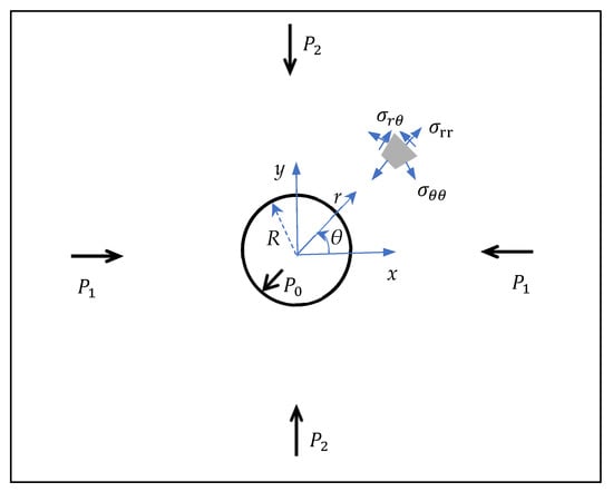
Figure 1.
Schematic of the borehole with internal (P0) and external (P1, P2) stress distributions.
The in-plane stress components σrr, σθθ, and σrθ in a homogeneous isotropic elastic body are obtained from the well-known Kirsch solution [42]:
The classical convention of elasticity for stresses, i.e., positive for tensile stress and negative for compressive stress, is assumed. The shear stress and asymmetric parts of normal stresses are due to the difference between the far field compressions at the two directions. For porous media, the stresses in the above expressions are the effective stresses and the effective far field compressions, while the internal pressures are the difference between the total values and the pore pressure.
On the internal surface r = R of the circular borehole, the radial stresses on all the radial lines are identical and equal to −P0. On the circle r = , the radial stresses on all the radial lines are also identical and equal to:
On the internal surface of the borehole, the circumferential stress varies with according to
If , the circumferential stress is positive (tensile) within the region around . This may result in tensile radial fractures.
The distributions of the analytic radial and circumferential stresses given in Equations (1) and (2) along various radial lines for a demonstration model case of a deep borehole are considered. The borehole has a radius of R = 0.35 m and a depth of 2000 m. The effective major and minor far-field horizontal compressive stresses and the effective vertical stress (the total stress minus pore pressure) at 2000 m depth are assumed to be P1 = 109.5 MPa, P2 = 57.68 MPa and P3 = 31.82 MPa, respectively. The total major and minor horizontal compressive stresses are calculated from an assumed relationship with the total vertical stress due to the gravity at a given depth, i.e., and 1.5. Values for and with given value for are within the range estimated from the Blanche 1 borehole in South Australia [29]. The pore pressure is assumed to be 10 and 20 MPa at 1000 m and 2000 m depths, respectively. The effective pressure on the borehole surface (i.e., mud pressure minus pore pressure) at 2000 m depth is P0 = 6.0 MPa. The distributions of the radial stresses on radial lines 0°, 22.5°, 45°, 67.5° and 90° are shown in Figure 2a. On the radial line with °, i.e., the minor horizontal stress springline, the compressive radial stress increases rapidly to its maximum value of 59.9 MP at r ≈ 2.44R = 0.855 m (Figure 2a), which is only slightly higher than the far-field compression (57.68 MPa). As noted above, the compressive radial stresses on all the radial lines are equal to 57.7 MPa at r =m. Within the region R < r <, the compressive radial stress increases with the polar angle and when r >, the compressive radial stress decreases with the polar angle .

Figure 2.
Distribution of the (a) radial and (b) circumferential stresses along five radial lines, 0°, 22.5°, 45°, 67.5° and 90° at 2000 m depth.
Figure 2b shows the distributions of the circumferential or hoop stress on the five radial lines around the circular hole. Near the circular borehole surface, the compressive circumferential stress on the line 90° is much higher than that on the line 0° and decreases rapidly in radial direction away from the borehole surface. On the borehole surface, the compressive circumferential stress is much higher than the compressive radial stress. The compressive circumferential stresses on the radial lines around the major horizontal stress springline ( first increase to a maximum value and then decrease with the radial distance (curves for and ). The position of the maximum value moves towards the borehole surface with the increase of the polar angle . Then within some region around the minor horizontal stress springline, the compressive circumferential stress decreases with the radial distance. Rapid change of the radial and circumferential stresses is observed within r < 3R.
2.2. Extensional Strain Criterion for Fracture Initiation
Fractures in materials occur because the relative displacement between adjacent points is too large and is larger than the strength of the material. Strains are related directly to the relative displacements and can be used to detect fracturing failure [41,43,44]. Extensional strain does not only exist in the direction of the tensile stress, it can also exist in the direction of the compressive stress due to the effect of Poisson’s ratio, if the compressive stresses in the orthogonal direction/s are large enough. If the extensional strain (measuring relative extensional displacement) in any direction is greater than the critical value, a tensile fracture perpendicular to this direction would form [43].
To derive the formulation of the extensional strain criterion, the stress convention in geomechanics, i.e., positive for compressive stresses, is used here. From linear elasticity theory for 2D plane stress problems, the in-plane normal strain in the direction of minor compressive principal stress, σ3, is given by:
where σ1 (>σ3) is the major compressive principal stress (MPa); ν and E are Poisson’s ratio and Young’s modulus of the material (MPa), respectively. The normal strain ε3 > 0 indicates compression and ε3 < 0 indicates extension. Therefore, if νσ1 > σ3, the strain becomes extensional even in regions where all stresses are compressive.
Furthermore, if the extensional strain value −ε3 is greater than the critical value, , then a fracture normal to the minor (compressive) principal stress direction is initiated. The critical is derived from the uniaxial tensile strength (UTS) [30,41]:
This is the extensional strain criterion for fracture initiation with plane stress conditions and can be satisfied in regions where the difference between the principal stresses is large [30,43]. With the critical value of the extensional strain derived from the uniaxial tensile strength as in Equation (7), the extensional strain criterion and tensile stress criterion for fracture initiation are equivalent in uniaxial tensile cases.
The extensional strain criterion in Equation (7) can explain the reason why rock spalling begins at the tunnel wall when the compressive stress at the wall reaches about 0.4 times the uniaxial compressive strength (UCS) of the rock [30]. This is a phenomenon that tunnelling engineers have noticed for a long time [45,46,47,48].
In plane strain cases, the normal stress perpendicular to the cross-sectional plane, , also contributes to the strain . This case includes generalised plane strain conditions where the normal strain perpendicular to the cross-sectional plane is uniform, but not zero. In such case, the extensional strain criterion would be:
The term may be referred-to as fracture initiation checking stress. With the same values of σ1 and σ3, tensile fractures will be initiated more likely in plane strain cases than in plane stress cases, or regions with tensile fractures would be larger in plane strain cases than that in plane stress cases. In the above Equations (6)–(8), the principal stresses σ1 and σ3 can be obtained from the stresses given in Equations (1)–(3).
2.3. Shear Stress Criterion for Fracture Initiation
Equation (3) gives the shear stresses in cylindrical coordinate planes, normal to the cylindrical coordinate radial and circumferential directions, with maximum values on the line with 45°. On this line, the maximum value is at r = √3 R and is equal to 2(P1 − P2)/3. Note that this is on the circle on which the radial stresses on all radial lines are the same.
Considering the tangential (shear) stresses on all possible planes at all points, the maximum value may be different from the above one on the coordinate planes. When the tangential (shear) stress on a plane is large enough to mobilise a shear failure criterion, such as the Mohr-Coulomb criterion, shear fractures could be initiated on the plane. Generally, at a given point, the maximum shear stress is on the plane perpendicular to the bisection direction between the principal stress directions.
2.4. Fracturing Regions around Boreholes
With the analytical solutions for stresses in radial and circumferential directions given in Equations (1)–(3), the stresses in the Cartesian coordinate directions and in-plane principal stresses can be derived. Next, with the extensional strain criterion (7) or (8) and shear criterion (9), the regions with incipient tensile and shear fractures can be obtained, respectively. In this section, we investigate such regions for various cases. Values of the mechanical parameters for fracture initiation are given in Table 1. These are based on the previous measurement and modelling data from Klee et al. [29]. The strengths are for a large rock mass with scale effects considered [40]. Brady and Brown [49] provided an equation to estimate the UCS values at different scales:
where dsmall and UCSsmall are the dimension and strength of a small sample, and dmass and UCSmass are the dimension and strength of mass sample. The UCS value of 112 MPa for a large rock mass corresponds to a UCS of 180 MPa of rock sample of 50–60 mm diameter. Two more rock masses of UCS of 74 MPa and 150 MPa (corresponding to UCS of 120 MPa and 240 MPa) are also considered. The uniaxial tensile strengths are assumed to be 1/10 of the UCS [50]. The value of cohesion is calculated from the uniaxial compressive strength and the internal friction angle according to the relation derived from the Mohr-Coulomb criterion. The stress state considered is that mentioned above for a depth of 2000 m.
UCSmass = (dsmall/dmass)0.18 × UCSsmall

Table 1.
Values of mass rock physical and mechanical parameters.
For a 2000 m deep borehole, the fracture initiation regions are shown in Figure 3. The distributions of corresponding stresses are shown in Figure 2. From the above analysis for stresses near the circular hole, the compressive circumferential stress on the line 90° is much higher than the compressive radial stress. On the line 0°, the difference between the two stresses is smaller. Thus, with the extensional strain criterion for tensile fracture initiation, the fractures parallel to the circular surface would be initiated around 90° more easily than around 0°.
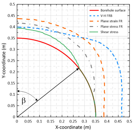
Figure 3.
Regions (FR) in which fractures would be initiated for rocks with UCS = 112 MPa at 2000 m depth predicted with analytical solutions, together with boundary between vertical fracture and horizontal fracture regions (V-H FRB). β is half the breakout span angle.
Tensile fractures would be initiated according to the extensional strain criterion (7) (plane stress FR) in the region enclosed by the grey dash-dotted curve and the red borehole surface (Figure 3). In the region enclosed by the orange long-dash curve and the red borehole surface, fractures will be initiated according to the criterion (8) (plane strain FR) with the effect of the vertical gravity stress 31.82 MPa. The green dotted curve and the borehole surface enclose the region in which shear fractures would be initiated if the Mohr-Coulomb criterion is employed (shear stress FR). The region for shear fractures is smaller than that for tensile fractures.
With generalised plane strain conditions, vertical gravity stress is always a principal stress. When the pressure on the borehole surface is smaller than the far field compressive stresses and the vertical gravity stress, within some region around the borehole, one of the in-plane principal stresses is smaller than the vertical principal stress and will be the minor compressive principal stress. Fractures initiated in this region would have vertical planes. If both far field horizontal compressive stresses are greater than the vertical stress, then the vertical stress will be the minor compressive principal stress in the area outside the vertical fracture region. If tensile fractures are initiated in the outer area, then they will be horizontal. The blue short-dash curve in Figure 3 is the boundary of the vertical fracture and horizontal fracture regions (V-H FRB) for the cases considered. The above 2D stress analysis is not able to identify such horizontal tensile fractures. Since these fractures are horizontal and borehole breakouts are caused by vertical or subvertical fractures [34], the horizontal tensile fractures do not form borehole breakouts directly. However, they could reduce rock strength.
Perras and Diederichs [48] numerically simulated various cases to obtain approximate formulae for prediction of the depths of the damage zones in brittle rocks. According to their results for granite, the stresses and rock strength used for the case shown in Figure 3 would predict the depth of the highly damaged zone (fractured) to be around 1.2 times the radius of the borehole. The boundary of the fracturing region on the y-axis from the plane stress criterion (7) in Figure 3 is at r = 0.42 m. This gives the depth of the fracturing region as r/R = 1.2. This agrees well with the Perras and Diederichs [48] prediction. Lin et al. [37] predicted the theoretical span angle 2β of the failure region on the borehole surface according to the condition that the circumferential stress expressed in Equation (2) at the point on the borehole surface reaches the rock mass compressive strength. With this condition, the theoretical prediction of the span angle of the failure region for above case is about 120°, which is close to that from the Mohr-Coulomb criterion shown in Figure 3. It is noted that this theoretical prediction is independent of the borehole size.
Although the extensional strain criteria predict deeper fracturing regions along the minor compressive principal stress springline than the Mohr-Coulomb shear criterion (Figure 3), the regions with vertical fractures for breakouts are bounded by the V-H FRB curve. As a result, the depth of breakout regions on the minor compressive principal stress springline from the extensional strain criteria is similar to that with Mohr-Coulomb shear criterion (Figure 3). The extensional strain criteria predict wider breakout regions with a larger span angle towards the major compressive principal stress springline than the Mohr-Coulomb shear criterion.
Figure 4 shows the effect of the rock mass UTS on the fracture regions for the stress state at 2000 m depth of the borehole, as shown in Figure 2, without effect of vertical gravity (plane stress criterion (7)). In addition to 11.2 MPa UTS, the weaker rock with 7.4 MPa UTS and the stronger rock with 15.0 MPa UTS were also used. For strong rocks of 15 MPa UTS, no fractures would be generated around the borehole at the direction of the major far field compressive stress. The boundaries of the regions for the three strengths on the y-axis are close to one another. It is noted that for weaker rocks with 7.4 MPa UTS, the stress state at far field, including the vertical gravity stress, satisfies the initiation criterion (8) for horizontal fractures. This means that in situ horizontal fractures could be initiated in the whole plane at 2000 m depth even without the borehole being drilled.

Figure 4.
Regions in which tensile fractures would be initiated according to the extensional strain criterion (7) at 2000 m depth for three UTS of rock mass: 15.0 MPa, 11.2 MPa and 7.4 MPa.
It should be noted that the above analysis only indicates that fractures could be initiated in these regions under the given instant static load, and what their orientation would be if they were initiated. This represents a snapshot for the given load. The load in real scenarios is dynamic and increases gradually, and the failure develops progressively. When the deformation state at a given point in the studied domain reaches the criterion in the loading process, a fracture is initiated at that point. After the initiation, the fracture could propagate, which would change the deformation conditions. When the load reaches the given static load, more fractures could be initiated and the stress conditions become different from those under the instant static load. Therefore, fractures may not be initiated at some points in the region or may be initiated at some points outside the region. The shape of the regions predicted with the above analytical solution may be different from the shape of the breakouts observed in the field and experiments.
The tensile fractures sub-parallel to the borehole surface initiated around the minor horizontal compression springline would extend and form thin rock layers. The thin layers are under high “in-plane” compression, and buckle and break out in flakes. Such a breakout is one type of breakout observed in rocks with a low porosity such as granite [34,51].
3. Is It Possible to Have In Situ Horizontal Fractures?
If, in three-dimensional problems, the in situ minimum principal stress is much smaller than the other two in situ principal stresses, and further the tensile strength of the rock is not high and Poisson’s ratio of the rock is large such that , then the extensional strain criterion for fracture initiation is satisfied, and fractures can be initiated in theory, even under the in situ stress state alone without any external disturbance. Such fractures could be called in situ fractures. Rock exfoliation joints [52] close to ground surface are similar to such fractures.
Near the ground surface, the vertical stress is small, compared to the horizontal in situ principal stresses, and is the minimum compressive principal stress. Horizontal in situ fractures can occur in the region according to the extensional strain criteria. As depth increases, the vertical stress increases and one of the horizontal in situ principal stresses becomes the minimum principal stress. If in situ fractures occur at depth, they will be primarily vertical. Orientations of possible in situ fractures are illustrated in Figure 5; above the line where the vertical stress is equal to the minimum horizontal principal stress , the in situ fractures will be horizontal, and below the line the in situ fractures will be vertical.
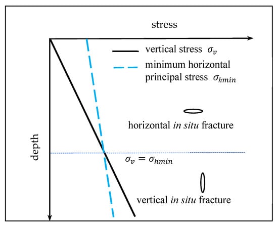
Figure 5.
Illustration for orientations of possible horizontal and vertical in situ fractures. Adapted from [53].
There are also situations at some depths in which both the major and minor horizontal in situ principal stresses are higher than the vertical stress. In theory, horizontal in situ fractures can then be initiated. For instance, in the above simulated borehole of 2000 m depth with effective stresses , , , if the rock tensile strength is 7.4 MPa and the Poisson’s ratio is 0.24, then . Under those conditions, horizontal in situ fractures are possible.
The above is a theoretical analysis and only fracture initiation is considered. The initiation may only create micro fractures. The vertical compressive stress could prevent the fractures from propagating. Is it possible to have in situ horizontal fractures in the field? It is well known that “parallel” horizontal discs are observed from many vertical borehole drilling cores [29,54]. It is believed that such discs are formed by tensile stress induced within the core during drilling. Is it possible for the fractures to exist before drilling? Flottmann et al. [54] found that horizontal, clay-filled tensile microfractures exist in thin sections of disced core from wells at depths around 2580 m at the Cooper Basin, central Australia. Occurrence of clay in the microfractures indicates that the microfractures are pre-existing, not due to drilling. Similar horizontal fractures were found at depths around 2750 m at the Williston Basin, USA [55] and at depth 2200 m at the Alberta Basin, Canada [56]. Different mechanisms for their formation were postulated. It was believed that the fractures in the Cooper Basin were formed due to high horizontal contact stresses at rock grains since the fractures cut through the grains. The fractures at the Williston Basin were due to high pore pressure from the expulsion of hydrocarbon from the encasing shale section, while those at the Alberta Basin were due to exhumation or basin rebound reducing the overburden stress.
4. Two-Dimensional Numerical Prediction of Fracturing
A comprehensive set of 2D numerical simulation models with the FRACOD [57,58] and Irazu [59] codes were presented by Shen et al. [40] for a similarly large-diameter, deep borehole. Shen et al. [40] first verified the codes and the model with field data from the Blanche 1 borehole in South Australia [29] and subsequently studied effects of various factors, including the rock strength, thermal stresses, pre-existing fractures and faults, as well as possible effects on the flow conductivity from the fractures. Results showed that where complex pre-existing fracture networks existed, the new fractures initiated in the borehole wall would propagate and coalesce with the pre-existing ones. The combined new and pre-existing fractures would form wider and deeper breakouts compared to conditions without pre-existing fracture networks. In this section, we present one of their simulation cases for verification with the analytical solution shown above. The FRACOD code is based on displacement discontinuity method for linear elastic problems. It has the advantage over some other numerical methods for fracture problems in that it discretises a fracture as a unity, not its two surfaces, thus leading to fewer number of equations to be solved. The basic unknowns, displacement discontinuity components, at the fracture tips can be used to calculate the stress intensity factors directly and check the propagation criterion, avoiding the need to calculate the stresses at fracture tips. It also explicitly traces the fracture propagation trajectory. There is no need for remeshing after a step of propagation. For details of FRACOD, the readers are referred to [57,58].
Irazu is developed by Geomecanica [59] and it uses an integrated finite element/discrete element-discrete fracture network approach. It is capable of simulating complex failure processes of rock masses. We included calculations with Irazu as it tends to deliver more realistic fracture patterns that are used to verify the FRACOD-derived patterns.
The case simulated with the 2D codes has a rock mass UCS of 150 MPa (sample UCS of 240 MPa), a rock mass UTS of 15 MPa and Poisson’s ratio of 0.31 with the stress state at 2000 m depth. The value of rock mass UCS used here is different from that used in previous studies [40,60] to explore borehole breakouts across a broader parameter range. The density, Young’s modulus, and internal friction angle of rock mass are given in Table 1. After initiation, the fractures propagate with rock open fracture toughness KIc =1.80 MPa m½ and shearing fracture toughness KIIc = 4.09 MPa m½. The joint properties of the fractures are as follows: normal stiffness Kn = 50,000 GPa/m, shear stiffness Ks = 1255 GPa/m, friction angle ϕ = 25.5°, dilation angle ϕd = 0.5°, and zero cohesion. The borehole surface is subjected to a mud pressure of 6 MPa.
Figure 6 shows the fractures around the borehole obtained from FRACOD with the extensional strain criterion (Figure 6a) and tensile stress criterion (Figure 6b) for fracture initiation. The fractures propagate after initiation and join on the borehole surface to form breakouts around the minimum compression springline, agreeing with results from the literature [34]. The extensional strain criterion predicts deeper and wider fractured regions than the tensile stress criterion. For the example shown, both the depth and width of the fractured regions from the extensional strain criterion are about double of those from the stress criterion. The simulated fractures with Irazu are shown in Figure 7. The extensional strain criterion in FRACOD predicts fracturing regions closer to those from Irazu than the tensile stress criterion. The fracturing regions from Irazu are deeper (around 40%) than those from FRACOD. The shape of the regions is similar to those by Shalev et al. [38] with mud pressure on the borehole surface.
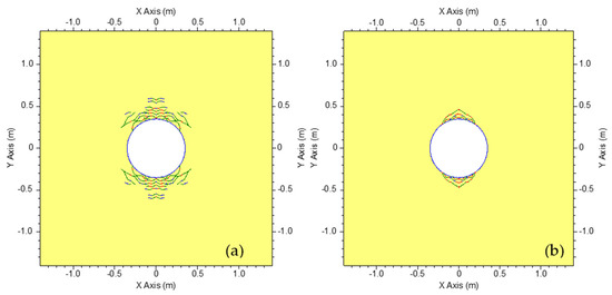
Figure 6.
Borehole fractures at 2000 m depth simulated with FRACOD and initiated with (a) extensional strain criterion and (b) stress criterion. Adapted from [40,60].

Figure 7.
Fractures around the borehole at 2000 m depth simulated with Irazu. The model domain is 6 m by 6 m (stress criterion only).
Due to the different methods used in the different numerical codes, the nature of the fractures is different. FRACOD employs the continuum displacement discontinuity method while Irazu uses the finite-discrete element method. The model implemented in FRACOD is a circular hole in an infinite domain, while in the Irazu code, the model has a finite domain of dimensions 6 × 6 m containing a circular hole.
Figure 8 illustrates the regions in which incipient fractures can be initiated according to the analytical solutions for stresses and the extensional strain criterion (Figure 8a) and Mohr-Coulomb shear criterion (Figure 8b) for fracture initiation. The effect of vertical stress is not considered. The curves represent three rock mass UCSs: 150.0 MPa, 112.0 MPa and 74.0 MPa (corresponding to rock UCSs: 240.0 MPa, 180 MPa and 120 MPa). From Figure 8 and the brown double dot-dashed curves for UCS: 150.0 MPa in Figure 8, the analytical prediction gives wider and shallower fracturing regions. This is because in the FRACOD simulations, fractures are initiated gradually and they propagate after initiation. Including these dynamic processes changes the stress state around the borehole, resulting in fracturing that progresses deeper in the y-axis and the stress concentration around the x-axis is relaxed somehow. The effect of the Poisson’s ratio on the fracture initiation is shown in Figure 4 (for 0.24) and 8a (for 0.31).
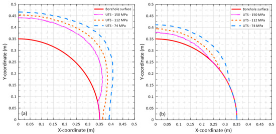
Figure 8.
Regions around the borehole in which fractures can be initiated according to (a) extensional strain criterion and (b) Mohr-Coulomb criterion, for three rock mass UCS: 150 MPa, 112 MPa and 74 MPa.
5. Thermal Effect on Fracturing Regions around Boreholes
5.1. Qualitative Analytical Evaluation
The borehole wall and the rock surrounding the borehole wall will experience different heat stresses throughout their lifetime. During drilling, mud is normally used to supply pressure on the borehole surface to reduce breakouts. This would cool the borehole surface from the in-situ temperature, potentially leading to fracture formation [40]. During the disposal of heat-generating spent fuel, high-level waste, and some intermediate-level waste, the temperature of the borehole surface and surrounding rock may increase significantly [61]. Depending on the magnitude of the heat load, the temperature increase could affect the stability of the borehole.
Because of the time-dependency of the temperature change, no closed form expression for the temperature change has been found in the literature. We have therefore undertaken a qualitative evaluation based on known analytical expressions. Results indicate that increasing temperature would enhance failure (fracture initiation) while decreasing temperature would reduce failure close to the borehole surface. Further details of the analysis are available in the Appendix A.
5.2. Numerical Simulation
The effect of temperature change on borehole stability is simulated using FRACOD with the extensional strain criterion for fracture initiation. To further explore breakouts with parameter values not previously shown in [40,60] and other work related to this project, the UCS and UTS of the rock mass are chosen to be 150 MPa and 15 MPa, respectively. The effective far field compressive horizontal stresses are 109.5 MPa and 42.5 MPa, which are derived from total horizontal stresses and with the total vertical stress evaluated at 2000 m depth and 20 MPa pore pressure. An effective internal pressure of 6 MPa is applied on the borehole surface. The values of other mechanical parameters are the same as those given above in Table 1 and Section 4. Thermal parameters for rock mass used are specific heat (714 J/kg °C), thermal conductivity (3.0 W/m °C) and linear thermal expansion coefficient (7.4 × 10⁻⁶/°C). Two temperature increases on the borehole surface due to the heat load from disposed radioactive waste were chosen: 6.5 °C (representing intermediate level waste) and 65 °C (representing high-level waste) [61].
From the results shown in Figure 9, both fracture initiation and propagation can be observed. At 6.5 °C temperature increase (Figure 9c), there is no noticeable change to the fracturing region compared to the reference case without temperature loading (Figure 9a). At 65 °C temperature increase (Figure 9d), some additional fractures were initiated around the minor principal stress springline. Overall, the effect is considered not significant within the range of temperature increases considered here. Decreasing temperature by 27 °C, on the other hand, leads to more fractures being initiated along the diagonal lines between the two principal stress directions (Figure 9b).
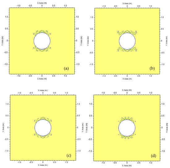
Figure 9.
FRACOD simulation of fracture initiation and propagation at 2000 m depth in a large-diameter borehole: (a) mechanical loading only, (b) temperature on borehole surface decreasing by 27 °C for 10 days, (c) temperature on borehole surface increasing by 6.5 °C for 10 years and (d) temperature on borehole surface increasing by 65 °C for 10 years. Adapted from [40,60].
6. Three-Dimensional Numerical Prediction of Fracturing with FRACOD3D
The 2D results shown above are valid on the horizontal cross-sectional planes of the vertical borehole some distance away from the bottom of the borehole. Around the bottom of the borehole, the 2D plane strain conditions are not valid, so the above results cannot be applied, and 3D models are needed to investigate borehole stability. Besides the stability around the bottom of the borehole, the 3D models can be used to crosscheck with the 2D solutions for positions some distance away from the bottom. At such positions, the 3D model can also predict horizontal fractures, while the 2D model cannot. In this section, we present the 3D results obtained by simulation with FRACOD3D. FRACOD3D is the 3D version of FRACOD, using the same/similar procedures for stress analysis with triangular elements [62,63].
In this study, only a 10 m long section of the borehole at the bottom end was simulated. The borehole was treated as a cylindrical cavity without traction on the top end and uniform pressure was applied to other parts of the borehole surface. At the middle part of the cavity, or some distance away from the borehole bottom, the generalized plane strain conditions for the 2D solution are satisfied and the above analytical solution and the 2D simulations can be used to predict fractures around the borehole. The simulation results with FRACOD3D for this part of borehole can be compared with the analytical and 2D numerical solutions. For the 3D simulations, the top and bottom of the borehole cavity were discretized with 5 segments in radial direction and 16 segments in circumferential direction. The cylindrical surface was discretized into 80 segments vertically.
In the numerical simulations of fracture initiation, new fractures are initiated at pre-specified grid points. The deformation response is instantaneous in that there is no lag of final deformation and action of the loading. The fracture initiation criterion can be satisfied at many grid points for a given load, and thus, fractures could be initiated at these points simultaneously. In real scenarios, mechanical loading increases continuously, and fractures are initiated at some points where the criterion is satisfied first. When the loading reaches the threshold value, the newly initiated fractures have changed their stress state, so at some points where the fracture initiation criterion was satisfied before, the criterion is not satisfied any more. Thus, in the numerical simulations, for a specified value of loading, fractures are initiated at grid points where the ratio of fracture initiation checking value (stress or strain) to the corresponding critical value is maximum. FRACOD3D allows eight fractures to be initiated at each step since there may be eight grid points, in three-dimensional symmetrical problems, at which the ratio reaches the same maximum value. Each new fracture has an octagon shape with equal sides. After the initiation, propagation of the fractures is considered. After a propagation step, new fractures can be initiated.
In the following, we present the results for 2000 m depth and with the values of mechanical parameters given in Table 1 and stresses used for Figure 4. Since the large Poisson’s ratio used above in the 2D simulations leads to in situ horizontal fractures in 3D, a lower value of 0.24 is used. The open fracture toughness KIc = 1.35 MPa m ½, shear fracture toughness KIIc = 3.07 MPa m ½ and tearing fracture toughness KIIIc = 100 MPa m1/2 for possible fracture propagation. The joint properties of the fractures have the following values: normal stiffness Kn = 10000 GPa/m, shear stiffness Ks = 1000 GPa/m, friction angle ϕ = 25.5°, dilation angle ϕd = 0.0° and cohesion is zero. The x-axis is along the major horizontal far-field stress direction and the y-axis is along the minor horizontal far-field stress direction.
Figure 10 shows the fractures initiated around the middle part of the borehole after a few steps. The newly initiated fractures do not propagate. Most of the fractures are vertical or sub-vertical, except two along the y-axis direction—the minor compression springline. These vertical fractures could contribute to borehole breakouts.
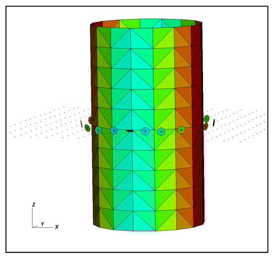
Figure 10.
Fractures (octagon shape) initiated half-way the height of the borehole section as simulated with FRACOD3D.
Figure 11 shows the fractures viewed from the vertical z-axis. The numbers in the parentheses are the in-plane coordinates of the grid points at which the fractures are initiated. The positions of the fractures are also shown in Figure 12 (blue dots) together with the 2D analytical prediction of fracture regions for the case with the effect of vertical stress (plane strain FR). Figure 12 also shows the boundary between the vertical and horizontal fracture regions (V-H FRB), on which the vertical stress is equal to the minor horizontal principal stress. Inside the V-H FRB, fractures would be vertical and outside the V-H FRB fractures would be horizontal. The horizontal fractures located on the y-axis are in the horizontal fracture regions and the vertical fractures at (0.3, 0.3) and (0.4, 0.1) are in the vertical fracture regions as predicted by the analytical solution. Note that the orientations of the vertical fractures at point (0.1, 0.4) and (0.2, 0.4) are not the same as predicted analytically.

Figure 11.
Fractures initiated around the middle part of borehole, viewed along the vertical direction from FRACOD3D.

Figure 12.
Analytical prediction of fracture region (plane strain FR) and the positions of fractures initiated in FRACOD3D simulation (blue dots) around the middle part of borehole, together with the boundary between vertical and horizontal fracture regions (V-H FRB).
Figure 13 illustrates the displacements (Figure 13a) and fractures (Figure 13b) initiated around the bottom of the borehole, where fractures were initiated more in the major horizontal far field compressive stress direction than in the minor stress direction. Ito et al. [36] and Shalev et al. [38] also predicted that borehole breakouts at the bottom of the borehole extend more in the direction of the maximum stress direction. Ito et al. [36] used a finite element method to investigate the three-dimensional stress field and breakout around the borehole, including the bottom of the borehole. It was found that on cross-sectional planes around the bottom of the borehole along the borehole, the position of the maximum equivalent stress for the von Mises yield criterion is on the maximum horizontal compression springline, while on cross-sectional planes at a distance away from the bottom, it is on the minimum horizontal compression springline. The maximum equivalent stress around the bottom of borehole is larger than the maximum equivalent stress at a distance away from the bottom. Shalev et al. [38] believed that the reason for the large extension of the failure region on the maximum horizontal compression springline at bottom of borehole is the upward displacement on the bottom which creates the maximum shear strain on the plane of largest displacement.
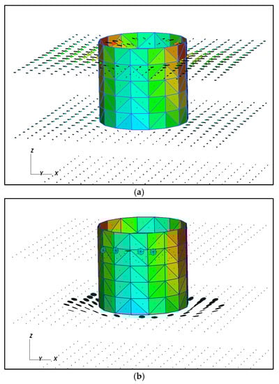
Figure 13.
(a) Displacements and (b) fractures initiated around the bottom of borehole at 2000 m depth.
It should be noted that the above analyses are static in that stress, deformation, and fracture initiation are the results from a borehole that was instantly formed in the rock medium. When a borehole is drilled in intact rock, the rock first experiences the stress and deformation field disturbances in the area around the bottom of the borehole. As the drilling of the borehole progresses, that part is no longer the bottom of the borehole. The stress and deformation disturbances in the area around this part of the borehole should be further developed on the basis of the stress and deformation field when that part was the bottom of the borehole. If the rock is damaged at the time when it was the bottom of borehole, then the 2D analysis for the further development should be based on the damaged rock. Ito et al. [36] mentioned this necessity but argued that the damaged region is small compared to the borehole size, so the effect can be ignored. From Figure 13b one can see that at the bottom of the borehole, the initiated fractures clearly extend beyond the size of the borehole. After the drill bit has passed this position for some distance, the stress state around this part of the borehole has changed to a “2D condition” and indeed further fracturing could result in an expansion of the initial fracture network. Such condition may provide pathways for the migration of radionuclides to the accessible environment, either dissolved in the fracture porewater or via a gas phase due to the formation of corrosion gases such as hydrogen [64].
Wherever such pathways occur along the disposal zone, detailed assessments need to be undertaken to verify if such fractures are critical to long-term safety or not. An example of such assessment is provided by Finsterle et al. [65]. They demonstrated that even with a poorly sealed borehole (with a permeability of fine sand), the radiological impact for the mobile radionuclide 129I is essentially identical, and negligible, to a scenario that considers a low-permeability backfill. The reason that the calculated radionuclide impact via a drinking water well was insensitive to the hydraulic properties of the backfill material is to be found in the very small contribution of radionuclides that migrate via the borehole compared to most of the radionuclides that migrate via the large volume of the host rock surrounding the disposal borehole. Note that for both the sealing and poor-sealing scenarios, a drilling damaged zone with a permeability 100 times higher than the surrounding host rock was included.
7. Summary and Conclusions
Deep borehole repositories are a potentially attractive solution for the disposal of small volumes of appropriately conditioned long-lived intermediate-level waste. The stability of the borehole is critical for waste emplacement while estimations of the borehole fracture network are required for post-closure safety assessments. In this paper, we first presented 2D analytical and numerical predictions of fracturing regions along the borehole of a demonstration model, under biaxial far field horizontal compression as well as vertical compression. The 2D numerical simulations were performed with codes FRACOD and Irazu. The analytical prediction and FRACOD employ the extensional strain criterion and Mohr-Coulomb shear criterion for fracture initiation. More fractures were aligned around the minor horizontal compression springline than around the major horizontal compression springline. Thermal effects on the fracturing regions were also investigated, both for cooling due to drilling fluid and heating from disposed radioactive waste. Numerical calculations showed negligible effects at low temperature loading (+6.5 °C) and small but insignificant effects at higher temperature loading (+65 °C). Cooling by 27 °C resulted in additional fractures being initiated along the diagonal lines between the two principal stress directions.
The 3D code FRACOD3D simulated the fractures around the bottom of the borehole. At positions some distance away from the bottom of the borehole, the 3D simulation predicted similar results as the 2D analyses. Around the bottom of the borehole, there are more fractures around the major horizontal compression springline than those around the minor horizontal compression springline, and the fractures are sub-horizontal.
A theoretical analysis using the extensional strain criterion for fracture initiation showed that it is possible for in situ horizontal fractures to be initiated under the far field stresses only, without any other actions. It is worth investigating whether such in situ horizontal fractures exist in the field.
Our previous work [40] showed that the hydraulic conductivity of the borehole wall can be increased by several orders of magnitude, especially when new fractures coalesce with pre-existing fractures. The effect of such higher permeability rock zones on radionuclide transport is the subject of future studies that will consider a vertical disposal borehole. We note again that previous assessments based on horizontal disposal boreholes indicated that boreholes with a higher permeability than the surrounding host rock, due to poor sealing and a continuous drilling damaged zone, did not produce an unacceptable radiological impact via a groundwater well [65].
Author Contributions
Conceptualization, D.M., B.S., J.S. and M.K.; Methodology, D.M., B.S., M.K. and J.S.; Software, B.S. and J.S.; Formal Analysis, J.S., B.S. and M.K.; Writing—Original Draft Preparation, J.S.; Writing—Review & Editing, D.M., J.S., B.S. and M.K.; Supervision, D.M.; Project Administration, D.M.; Funding Acquisition, D.M. All authors have read and agreed to the published version of the manuscript.
Funding
This study was supported by the CSIRO Interchange Round 1 programme.
Institutional Review Board Statement
Not applicable.
Informed Consent Statement
Not applicable.
Data Availability Statement
Available on request.
Conflicts of Interest
The authors declare no conflict of interest.
Appendix A
To investigate the thermal effects on fracture initiation, we define the thermal stresses as , and in the three principal stress directions, respectively. The compressive thermal stress due to temperature increase is defined to be positive, consistent with the definition for stresses from mechanical loading to calculate fracture initiation. The analytical expressions for thermal stresses due to temperature change T are given in [66]
Here is the linear thermal expansion coefficient of the rock mass. With uniform thermal conditions on the borehole surface, such as those considered here, the temperature change will be axisymmetric and T will depend on the radial distance r only. Because of the time-dependency of the temperature change, no closed form expression for the temperature change has been found from the literature. Therefore, the thermal stresses have not been expressed explicitly in terms of position variables and time, and their effect on fracture initiation has not been evaluated point-wisely. However, some qualitative evaluation was obtained and is presented in the following.
For initiation of tensile fractures with extensional strain criterion, the fracture initiation checking stress is
In the case where the vertical stress is the minimum principal stress, the thermal principal stresses related to temperature change T have the following properties
The fracture initiation checking stress becomes
Increase of temperature would give positive and the fracture initiation checking stress would be smaller than that without thermal effects:
Thus, an increase in temperature would reduce the possibility for horizontal extensile fracture initiation under compressive stress state. In contrast, a cooling process ( would enhance initiation of horizontal extensile fractures.
Around the borehole surface, the radial stress is the minimum principal stress and thus
These lead to the fracture initiation checking stress
According to the sign convention, temperature increase will lead to , and positive circumferential thermal stresses. Thus . The term in brackets of the fracture initiation checking stress is
and could be positive or negative. The fracture initiation checking stress with the thermal effect could be larger or smaller than that without the thermal effect. Therefore, the thermal effect on the initiation of vertical extensile fractures at a general position is not obvious.
As temperature decreases, and the circumferential thermal stress should be negative and thus . In this case, the term in brackets of the fracture initiation checking stress is
Since it is not clear whether the fracture initiation checking stress with the thermal effect is larger or smaller than that without the thermal effect, and therefore, the effect of decreasing temperature on initiation of vertical extensile fractures at a general position is not obvious too.
However, on the borehole surface, . For points close to the borehole surface, will be small and the term in the brackets of the fracture initiation checking stress in (A9) is positive when temperature increases and negative when temperature decreases. Thus, increasing temperature (heating) will enhance initiation of vertical extensile fractures and decreasing temperature (cooling) will reduce possibility for initiation of vertical extensile fractures close to the borehole surface.
The result of less extensile fractures by decreasing temperature (cooling) does not agree with common concepts based on the tensile stress criterion that contraction from cooling would help create more tensile fractures. As extensile fractures can be created under triaxial compressions, the triaxial tensions can also prevent extensile fractures being initiated due to the Poisson’s ratio effect.
It is noted that this discussion is about the fracture/failure initiation region for a given heat loading and is not related to fracture propagation after the initiation. Furthermore, these results are valid only close to the borehole surface and they may not be true at some distance away from the borehole surface. The thermal effect on failure regions with the fracture propagation could be different from that on initiation regions.
With the Mohr-Coulomb shear criterion
around the borehole, the circumferential stress is the in-plane major principal compressive stress and radial stress is the in-plane minor principal stress . The circumferential and radial thermal stresses are and , respectively. So, including the thermal stresses, the rock mass will fail when
It is also not obvious whether (A12) or (A13) is first satisfied. As above with the extensional strain criterion, at the borehole surface, , and close to the borehole surface, is small, and (A13) is approximated as
It can be seen from this again that increasing temperature would enhance failure while decreasing temperature would reduce failure close to the borehole surface.
References
- IAEA. Classification of Radioactive Waste: General Safety Guide; IAEA Safety Standards Series No GSG-1, IAEA (2003); International Atomic Energy Agency: Vienna, Austria, 2009. [Google Scholar]
- Birkholzer, J.; Houseworth, J.; Tsang, C.F. Geologic Disposal of High-Level Radioactive Waste: Status, Key Issues, and Trends. Annu. Rev. Environ. Resour. 2012, 37, 79–106. [Google Scholar] [CrossRef]
- MacKinnon, R.J.; Mayer, S.J.; Sevougian, S.D.; van Luik, A. Need for and Use of Generic and Site-Specific Underground Research Laboratories to Support Siting, Design and Safety Assessment Developments. In Proceedings of the WM2015 Conference, Phoenix, AR, USA, 15–19 March 2015. [Google Scholar]
- NWTRB. Filling the Gaps: The Critical Role of Underground Research Laboratories in the US Department of Energy Geological Disposal Research and Development Program; A Report to the US Congress and the Secretary of Energy; US Nuclear Waste Technical Review Board (NWTRB): Arlington, VA, USA, 2020. [Google Scholar]
- NWTRB. Survey of National Programs for Managing High-Level Radioactive Waste and Spent Nuclear Fuel: Update; A Report to the US Congress and the Secretary of Energy; Nuclear Waste Technical Review Board (NWTRB): Arlington, VA, USA, 2016. [Google Scholar]
- Haapalehto, S. Geological Mapping of Borehole Breakouts Observed in Acoustical and Optical Borehole Imagery of Deep Drillholes of Olkiluoto, Finland. Master’s Thesis, University of Helsinki, Helsinki, Finland, 2017. [Google Scholar]
- Chapman, N.A. Who Might Be Interested in a Deep Borehole Disposal Facility for Their Radioactive Waste? Energies 2019, 12, 1542. [Google Scholar] [CrossRef] [Green Version]
- Freeze, G.A.; Stein, E.; Brady, P.V.; Lopez, C.; Sassani, D.; Travis, K.; Gibb, F.; Beswick, J. Deep Borehole Disposal Safety Case. Energies 2019, 12, 2141. [Google Scholar] [CrossRef] [Green Version]
- Mallants, D.; Travis, K.; Chapman, N.; Brady, P.V.; Griffiths, H. The State of the Science and Technology in Deep Borehole Disposal of Nuclear Waste. Energies 2020, 13, 833. [Google Scholar] [CrossRef] [Green Version]
- Åhäll, K.I. Final Deposition of High-Level Nuclear Waste in Very Deep Boreholes; Report 2; Swedish NGO Office of Nuclear Waste Review (MKG): Göteborg, Sweden, 2006; p. 28. [Google Scholar]
- Juhlin, C.; Sandstedt, H. Storage of Nuclear Waste in Very Deep Boreholes: Feasibility Study and Assessment of Economic Potential. In SKB Tech. Report, 89-39; Swedish Nuclear Fuel and Waste Management Co.: Stockholm, Sweden, 1989. [Google Scholar]
- Pusch, R. SKB Technical Report 89-32: Influence of Various Excavation Techniques on the Structure and Physical Properties of “Near-Field” Rock around Large Boreholes; Technical Report for SKB: Stockholm, Sweden, 1989. [Google Scholar]
- SKB. Choice of Method—Evaluation of Strategies and Systems for Disposal of Spent Nuclear Fuel; Swedish Nuclear Fuel and Waste Management Company P-10-47: Stockholm, Sweden, 2010; p. 87. [Google Scholar]
- Brady, P.V.; Arnold, B.W.; Freeze, G.A.; Swift, P.N.; Bauer, S.J.; Kanney, J.L.; Rechard, R.P.; Stein, J.S. Deep Borehole Disposal of High-Level Radioactive Waste; Sandia National Laboratories: Albuquerque, NM, USA, 2009. [Google Scholar]
- Brady, P.V.; Freeze, G.A.; Kuhlman, K.L.; Hardin, E.L.; Sassani, D.C.; MacKinnon, R.J. Deep Borehole Disposal of Nuclear Waste: US perspective. In Geological Repository Systems for Safe Disposal of Spent Nuclear Fuels and Radioactive Waste, 2nd ed.; Apted, M., Ahn, J., Eds.; Woodhead Publishing: Duxford, UK, 2017; pp. 89–112. [Google Scholar]
- Finsterle, S.; Muller, R.A.; Baltzer, R.; Payer, J.; Rector, J.W. Thermal Evolution Near Heat-generating nuclear waste canisters disposed in horizontal drillholes. Energies 2019, 12, 596. [Google Scholar] [CrossRef] [Green Version]
- Beswick, J. Status of Technology for Deep Borehole Disposal NP 01185; EPS International for the Nuclear Decommissioning Authority: London, UK, 2008. [Google Scholar]
- Gibb, F.G.F.; Travis, K.P.; Hesketh, K.W. Deep Borehole Disposal of Higher Burn up Spent Nuclear Fuels. Mineral. Mag. 2012, 76, 3003–3017. [Google Scholar] [CrossRef]
- Bracke, G.; Kudla, W.; Rosenzweig, T. Status of Deep Borehole Disposal of High-Level Radioactive Waste in Germany. Energies 2019, 12, 2580. [Google Scholar] [CrossRef] [Green Version]
- Ji, S.H.; Ko, Y.K.; Choi, J.W. The State-of-the Art of the Borehole Disposal Concept for High Level Radioactive Waste. J. Korean Radioact. Waste Soc. 2012, 10, 55–62. [Google Scholar] [CrossRef]
- Kim, J.M. Deep Borehole Disposal of High-Level Radioactive Waste and Spent Nuclear Fuel. J. Geol. Soc. Korea 2015, 51, 425–431. [Google Scholar] [CrossRef]
- Park, B.; Kwon, S.; Min, K.-B.; Bona, B.; Sae-ha, K.; Min, U. The Status and Outlook of High-Level Radioactive Waste Disposal in Deep Borehole Focusing on Behaviour of Large-diameter Deep Borehole. J. Korean Soc. Miner. Energy Resour. Eng. 2017, 377–388. [Google Scholar]
- Kochkin, B.; Malkovsky, V.; Yudintsev, S.; Petrov, V.; Ojovan, M. Problems and Perspectives of Borehole Disposal of Radioactive Waste. Prog. Nucl. Energy 2021, 139, 103867. [Google Scholar] [CrossRef]
- Beswick, A.J.; Gibb, F.G.F.; Travis, K.P. Deep Borehole Disposal of Nuclear Waste: Engineering Challenges. Proc. Inst. Civ. Eng. Energy 2014, 167, 47–66. [Google Scholar] [CrossRef] [Green Version]
- Freeze, G.; Sassani, D.; Brady, P.V.; Hardin, E.; Mallants, D. The Need for a Borehole Disposal Field Test for Operations and Emplacement–# 21220. In Proceedings of the Waste Management 2021 Symposium, Phoenix, AR, USA, 7–11 March 2021. [Google Scholar]
- Rigali, M.J.; Hardin, E.L.; Stein, E.; Su, J.C. Large Diameter Deep Borehole Disposal Concept for HLW Glass; SAND2017-0130C; Sandia National Lab: Albuquerque, NM, USA, 2017. [Google Scholar]
- Brady, P.V.; Arnold, A.; Altman, S.; Vaughn, P. Deep Borehole Disposal of Nuclear Waste: Final Report; SAND2012-7789; Sandia National Lab: Albuquerque, NM, USA, 2012. [Google Scholar]
- Mallants, D.; Beiraghdar, Y. Radionuclide Transport and Deep Borehole Disposal: Preliminary Safety Assessments 21202. In Proceedings of the Waste Management 2021 Symposium, Phoenix, AR, USA, 7–11 March 2021. [Google Scholar]
- Klee, G.; Bunger, A.; Meyer, G.; Rummel, F.; Shen, B. In Situ Stresses in Borehole Blanche-1/South Australia Derived from Breakouts, Core Discing and Hydraulic Fracturing to 2 km Depth. Rock Mech. Rock Eng. 2011, 44, 531–540. [Google Scholar] [CrossRef]
- Shen, B.; Barton, N. Rock Fracturing Mechanisms around Underground Openings. Geomech. Eng. 2018, 16, 35–47. [Google Scholar] [CrossRef]
- Lin, H.; Oh, J.; Canbulat, I.; Stacey, T.R. Experimental and Analytical Investigations of the Effect of Hole Size on Borehole Breakout Geometries for Estimation of In Situ Stresses. Rock Mech. Rock Eng. 2020, 53, 781–798. [Google Scholar] [CrossRef]
- Pusch, R.; Ramqvist, G.; Kasbohm, J.; Knutsson, S.; Mohammed, M.H. The Concept of Highly Radioactive Waste (HLW) Disposal in Very Deep Boreholes in a New Perspective. J. Earth Sci. Geotech. Eng. 2012, 2, 1–24. [Google Scholar]
- Bradley, W.B. Failure of Inclined Boreholes. J. Energy Resour. Tech. 1979, 101, 232–239. [Google Scholar] [CrossRef]
- Haimson, B. Micromechanisms of Borehole Instability Leading to Breakouts in Rocks. Int. J. Rock Mech. Min. Sci. 2007, 44, 157–173. [Google Scholar] [CrossRef]
- Hu, H.G.; Guan, X.C.; Shor, R.; Xu, Y.Q.; Han, C.; Liu, Y.W.; Lu, B.P. Dynamic Response and Strength Failure Analysis of Bottomhole Underbalanced Drilling Condition. J. Petro. Sci. Eng. 2020, 194, 107561. [Google Scholar] [CrossRef]
- Ito, T.; Kurosawa, K.; Hayashi, K. Stress Concentration at the Bottom of a Borehole and Its Effect on Borehole Breakout Formation. Rock Mech. Rock Eng. 1998, 31, 153–168. [Google Scholar] [CrossRef]
- Lin, H.S.; Oh, J.; Canbulat, I.; Hebblewhite, B.; Hasoumi, H.; Walsh, S. Experimental Study on Borehole Size Effect and Prediction of Breakout Initiation Stress. Int. J. Rock Mech. Min. Sci. 2021, 142, 104762. [Google Scholar] [CrossRef]
- Shalev, E.; Bauer, S.J.; Homel, M.A.; Antoun, T.H.; Herbold, E.B.; Vorobiev, O.Y.; Levin, H.; Oren, G. Borehole Breakouts Modelling in Arkose and Granite Rocks. Geomech. Geophys. Feo-energ. Geo. Res. 2021, 7, 15. [Google Scholar]
- Liu, W.J.; Zhou, Y.L.; Zhu, X.H.; Meng, X.N.; Liu, M.; Abdel Wahab, M. Numerical Modelling of Bottom-Hole Rock in Underbalanced Drilling Using Thermo-Poroelasto-Plasticity Model. Struct. Eng. Mech. 2019, 69, 537–545. [Google Scholar] [CrossRef]
- Shen, B.; Shi, J.; Khanal, M.; Mallants, D. Geomechanical Modelling of Borehole Stability for Deep Borehole Radioactive Waste Disposal. In Proceedings of the Waste Management Symposium 2022, Phoenix, AR, USA, 6–10 March 2022. [Google Scholar]
- Barton, N.; Shen, B. Extension Strain and Rock Strength Limits for Deep Tunnels, Cliffs, Mountain Walls and the Highest Mountains. Rock Mech. Rock Eng. 2018, 51, 3945–3962. [Google Scholar] [CrossRef]
- Sokolnikoff, I.S. Mathematical Theory of Elasticity, 2nd ed.; McGraw-Hill: New York, NY, USA, 1956; pp. 286–292. [Google Scholar]
- Stacey, T.R. A Simple Extension Strain Criterion for Fracture of Brittle Rock. Int. J. Rock Mech. Min. Sci. Abstr. 1981, 18, 469–474. [Google Scholar] [CrossRef]
- Chang, K.J. On the Maximum Strain Criterion—A New Approach to the Angled Crack Problem. Eng. Fract. Mech. 1981, 14, 107–124. [Google Scholar] [CrossRef]
- Diederichs, M.S. Rock Fracture and Collapse under Low Confinement Conditions. Rock Mech. Rock Eng. 2003, 36, 339–381. [Google Scholar] [CrossRef]
- Diederichs, M.S. The 2003 Canadian Geotechnical Colloquium: Mechanistic Interpretation and Practical Application of Damage and Spalling Prediction Criteria for Deep Tunnelling. Can. Geotech. J. 2007, 44, 1082–1116. [Google Scholar] [CrossRef]
- Martin, C.D.; Kaiser, P.K.; McCreath, D.R. Hoek-Brown Parameters for Predicting the Depth of Brittle Failure Around Tunnels. Can. Geotech. J. 1999, 36, 136–151. [Google Scholar] [CrossRef]
- Perras, M.A.; Diederichs, M.S. Predicting Excavation Damage Zone Depths in Brittle Rocks. J. Rock Mech. Geotech. Eng. 2016, 8, 60–74. [Google Scholar] [CrossRef] [Green Version]
- Brady, B.H.G.; Brown, E.T. Rock Mechanics for Underground Mining; George Allen and Unwin: London, UK, 1985; p. 527. [Google Scholar]
- Cai, M. Practical Estimates of Tensile Strength and Hoek–Brown Strength Parameter mi of Brittle Rocks. Rock Mech. Rock Eng. 2010, 43, 167–184. [Google Scholar] [CrossRef]
- Zang, A.; Stephansson, O. Stress Field of the Earth’s Crust; Springer: Dordrecht, The Netherlands, 2010; p. 324. [Google Scholar]
- Holzhausen, G.R. Origin of Sheet Structure, 1. Morphology and Boundary Conditions. Eng. Geology 1989, 27, 225–278. [Google Scholar] [CrossRef]
- Mallants, D.; Jeffrey, R.; Zhang, X.; Wu, B.; Kear, J.; Chen, Z.; Wu, B.; Bekele, E.; Raiber, M.; Apte, S.; et al. Review of plausible chemical migration pathways in Australian coal seam gas basins. Int. J. Coal Geol. 2018, 195, 280–303. [Google Scholar] [CrossRef]
- Flottmann, T.; Campagna, D.J.; Hillis, R.; Warner, D. Horizontal Microfractures and Core Discing in Sandstone Reservoirs, Cooper Basin, Australia. In Proceedings of the PESA Eastern Australasian Basins Symposium II, Adelaide, Australia, 19–22 September 2004; pp. 689–694. [Google Scholar]
- Pitman, J.K.; Price, L.C.; Lefever, J.A. Diagenesis and Fracture Development in the Bakken Formation, Williston Basin: Implications for Reservoir Quality; U.S. Geological Survey Professional Paper 1653; U.S. Department of the Interior, U.S. Geological Survey: Washington, DC, USA, 2001. [Google Scholar]
- Fattahi, S.; Hopkins, J.; Putman, P. Paragenetic evolution of the Mississippian Pekisko Formation at Minnehik0-Buck Lake, Alberta, Canada. In Proceedings of the GeoCanada 2000 Core Workshop, Canadian Society of Exploration Geophysicists National Convention, Calgary, Canada, 1–2 June 2002. [Google Scholar]
- Shen, B.; Stephansson, O.; Rinne, M. Modelling Rock Fracturing Processes, A Fracture Mechanics Approach Using FRACOD.; Springer: Dordrecht, The Netherlands, 2014; ISBN 978-94-007-6903-8. [Google Scholar]
- Shen, B.; Stephansson, O.; Rinne, M. Modelling Rock Fracturing Processes with FRACOD. In Modelling Rock Fracturing Processes—Theories, Methods and Applications, 2nd ed.; Shen, I., Stephansson, O., Rinne, M., Eds.; Springer Nature: Cham, Switzerland, 2020; pp. 105–134. [Google Scholar]
- Geomechanica, Inc. Irazu 2D Geomechanical Simulation Software. 2021. Available online: https://www.geomechanica.com/ (accessed on 1 April 2021).
- Mallants, D.; Phalen, J.; Griffiths, H. Deep borehole disposal of intermediate-level waste. Saf. Nucl. Waste Disposal 2021, 1, 263–264. [Google Scholar] [CrossRef]
- Mallants, D.; Beiraghdar, Y. Heat transport in the near field of a deep vertical disposal borehole: Preliminary performance assessments–21195. In Proceedings of the WM2021 Conference, Phoenix, AR, USA, 7–11 March 2021. [Google Scholar]
- Shi, J.; Shen, B. FRACOD3D: A Three-Dimensional Crack Growth Simulator Code. In Modelling Rock Fracturing Processes–Theories, Methods and Applications, 2nd ed.; Shen, B., Stephansson, O., Rinne, M., Eds.; Springer Nature: Cham, Switzerland, 2020; pp. 135–172. [Google Scholar]
- Shi, J.; Shen, B.; Stephansson, O.; Rinne, M. A Three-Dimensional Crack Growth Simulator with Displacement Discontinuity Method. Engng. Anal. Boun. Elem. 2014, 48, 73–86. [Google Scholar] [CrossRef]
- Ortiz, L.; Volckaert, G.; Mallants, D. Gas generation and migration in Boom Clay, a potential host rock formation for nuclear waste storage. Eng. Geol. 2002, 64, 287–296. [Google Scholar] [CrossRef]
- Finsterle, S.; Cooper, C.; Muller, R.A.; Grimsich, J.; Apps, J. Sealing of a Deep Horizontal Borehole Repository for Nuclear Waste. Energies 2020, 14, 91. [Google Scholar] [CrossRef]
- Kumar, P.; Singh, B. Thermal stress analysis of underground openings. Int. J. Num. Anal. Meth. Geomech. 1989, 13, 411–425. [Google Scholar] [CrossRef]
Publisher’s Note: MDPI stays neutral with regard to jurisdictional claims in published maps and institutional affiliations. |
© 2022 by the authors. Licensee MDPI, Basel, Switzerland. This article is an open access article distributed under the terms and conditions of the Creative Commons Attribution (CC BY) license (https://creativecommons.org/licenses/by/4.0/).