Article

Exhaust Emissions from Plug-in and HEV Vehicles in Type-Approval Tests and Real Driving Cycles

1
Faculty of Civil and Transport Engineering, Poznan University of Technology, pl. M. Sklodowskiej-Curie 5, 60-965 Poznan, Poland
2
Institute of Vehicles and Construction Machinery Engineering, Warsaw University of Technology, ul. Narbutta 84, 02-524 Warsaw, Poland
3
Department of Vehicles and Fundamentals of Machine Design, Lodz University of Technology, ul. Stefanowskiego 1/15, 90-924 Lodz, Poland
4
Ecotechnology Team, Lodz University of Technology, 266 Piotrkowska Street, 90-924 Lodz, Poland
*
Author to whom correspondence should be addressed.
Energies 2022, 15(7), 2423; https://doi.org/10.3390/en15072423
Submission received: 27 February 2022 / Revised: 18 March 2022 / Accepted: 22 March 2022 / Published: 25 March 2022
(This article belongs to the Special Issue Development of Electric Vehicles and Engine Emissions)

Abstract

:
The amount of hybrid vehicles and their contribution have increased in the global market. They are a promising aspect for a decrease in emissions. Different tests are used to determine the factors of such emissions. The goal of the present study was to compare the emissions of two hybrid vehicles of the same manufacturer: the plug-in version and the HEV version (gasoline + electric engine). These vehicles were chosen because they comprise the largest market share of hybrid cars in Poland. The exhaust emission tests were conducted in the WLTC tests on a chassis dynamometer and under real traffic conditions. Simultaneous testing on a dyno and under real driving is the most adequate test to assess the environmental aspects of vehicles—especially hybrids. The combustion engines of the tested vehicles were supplied with gasoline containing 5% biocomponents. The emissions, including CO2, CO, NOx, THC and PNs, were measured in accordance with the European Union procedure. According to the latter, the resistance to motion of the chassis dyno was adjusted to the road load, allowing the hybrid vehicles to move in electric mode and allowing the dynamometer to operate in energy recovery mode. The obtained emissions of CO2, CO, NOx and THC in the case of the plug-in hybrid vehicle were lower by 3%, 2%, 25%, and 13%, respectively, compared to the case of HEV. Fuel consumption in the case of the plug-in hybrid vehicle was lower by 3%, and PN was lower by 10% compared to the case of HEV (WLTC). In real driving conditions, the differences were more pronounced in favour of the plug-in vehicle: CO2 emissions in the RDE test were 30% lower, NOx emissions were 50% lower, and PN was 10% lower. An increase in emissions was only observed for CO2 emissions—the plug-in vehicle’s on-road emissions were 6% higher compared to the HEV. The obtained emissions for FC and PN varied with actual velocity values due to competitive driving between a combustion engine and an electric motor, as well as existing acceleration and deceleration events during the test and other factors.

1. Introduction

The number of vehicles has continued to increase, resulting in heightened emissions, which has turned out to be an important problem that must be resolved in the coming years across the world. According to [1], the EU’s post-2021 CO2-weakening demand for passenger cars is 37.5% by 2030. This can be achieved by enhancing the amount of electric and hybrid vehicles in the continuously rising global population of manufactured vehicles, and various strategies exist that focus on this target. Hybrid electric vehicles (HEVs) play an important role in decreasing PM and NOx emissions [2]. Hybrid electric vehicles (HEVs) are also promoted in China [3].
Determining the environmental aspects of hybrid vehicles is important due to the ever increasing popularity of this type of vehicle. The growth in HEV and EV sales in the United States alone in the last quarter of 2021 was 11% of all light vehicle sales. Sales in HEVs increased by 6.1%, PHEVs by 1.4%, and EV by 3.4% (Figure 1). This is the result of a decrease in sales of internal combustion engine (ICE)-only cars and an increase in HEV model offerings. As of 2021, the number of HEV models in the United States has increased by 126% compared to 49% for non-hybrid vehicles [4].
According to [1], using plug-in hybridization and other design innovations together, the target can be met without the need for full EVs. The use of mild hybrids is the most effective method of CO2 weakening, followed by full hybrids and plug-in hybrids, but only if they are operated on battery. The amount of CO2 produced by electricity generation is greater than for gasoline, but it can be assumed that they are equal.
The authors of [5] evaluated the power engagement and emissions of passenger cars fitted with various powertrain systems during real driving. It was found that the order of power engagement (from lowest to highest) was an electric vehicle (EV), a plug-in hybrid vehicle (PHEV—with about 10% higher power engagement than a fully EV), and a conventionally powered vehicle (about 30% higher power engagement than an EV). In another study [6], a conventional vehicle and a hybrid vehicle were tested. It was shown that CO2 and CO emissions were much less for the HEV; HC and NOx emissions were near each other and at a low level. This indicates the validity of using hybrid vehicles in terms of lower power engagement as well as reduced emissions.
As was explained in [7], HEVs operate utilizing two different power sources, including petrol/diesel/gas engine and electricity. The three main types of HEVs include full hybrids, mild hybrids, and plug-ins.
Galassi et al. [8] explained that electric vehicles (EVs) exhibit a relatively high energy efficiency that is affected by various factors, such as accessory use and ambient temperature. The real energy efficiency variability directly influences the electric driving range of EVs, and thus, emissions decrease. However, limited driving range and long recharging times strongly inhibit the broad diffusion of EVs and HEVs.
Cieślik et al. [9] conducted research with a vehicle equipped with an electrified powertrain to reduce vehicle power engagement on warm days. The study included two drives in the summer and winter with the same vehicle driven by the same driver. Gerber et al. [10] analysed the road transport infrastructure in one region of America in relation to the possible maximal decrease in greenhouse gas (GHG) emissions and pollutants. They also analysed the unit investment cost of the vehicle. The authors found that HEVs, BEVs and hydrogen fuel-cell EVs effectively decreased pollutants and GHG emissions the most, but there were barriers, including not enough financial support for deployment of such vehicles.
Temporelli et al. [11] reported that despite high differences in the estimations of the ratio of CO2eq emissions and cell capacity (kWh), ranging from 50 to 313 g CO2eq/kWh, EVs exhibit lower carbon-intensive emissions during their mileages than similar diesel or petrol vehicles.
According to [12], an increase in car mobility and ownership may cause the share of PHEVs or BEVs to be 97% by 2050, jointly with a high weakening of GHGs emission from electricity production.
However, using a vehicle stock turnover model, and focusing on Japan [13], the authors estimated that by 2050, tank-to-wheel CO2 emissions will weaken by 42.8% in the base scenario, as the result of weakening vehicle numbers and fuel consumption and the use of HEVs. They found that powertrain electrification cannot guarantee the achievement of any of the CO2 emission reduction targets in road freight transport.
Fulton [14] simulated the influences of solar recharging of EVs on profits for the client and on the environment simultaneously, showing how solar-based charging of BEVs and HEVs decreased carbon emissions over grid-based one. They proposed two scenarios, allowing for a quick break-even for both BEV and PHEV variants over ICEV, with a two-fold decrease in CO2 emissions compared to the gasoline option (including production emissions).
The best topology, component selections, and controls are needed for HEVs to simultaneously reach: high fuel efficiency and performance, together with low emissions and costs.
Zhuang et al. [15] compared two frameworks combining three design dimensions together. The first approach was completely nested optimization searching via the entire design space. The second was an improved iterative optimization in which a sequential topological optimization was performed. The latter method allowed for one to obtain an optimal design with better computational efficiency.
In another study [16], the authors investigated the effect of ICE operating conditions on the flow of electrical energy in hybrid-type drives in two modes: normal driving and engine braking override. After tests with different variants, a similar final battery charge value was observed, indicating various manners of energy flow management in the tested driving modes. Although hybrid vehicles can decrease emissions, their ability depends on many components, including the configurations of the mentioned vehicles.

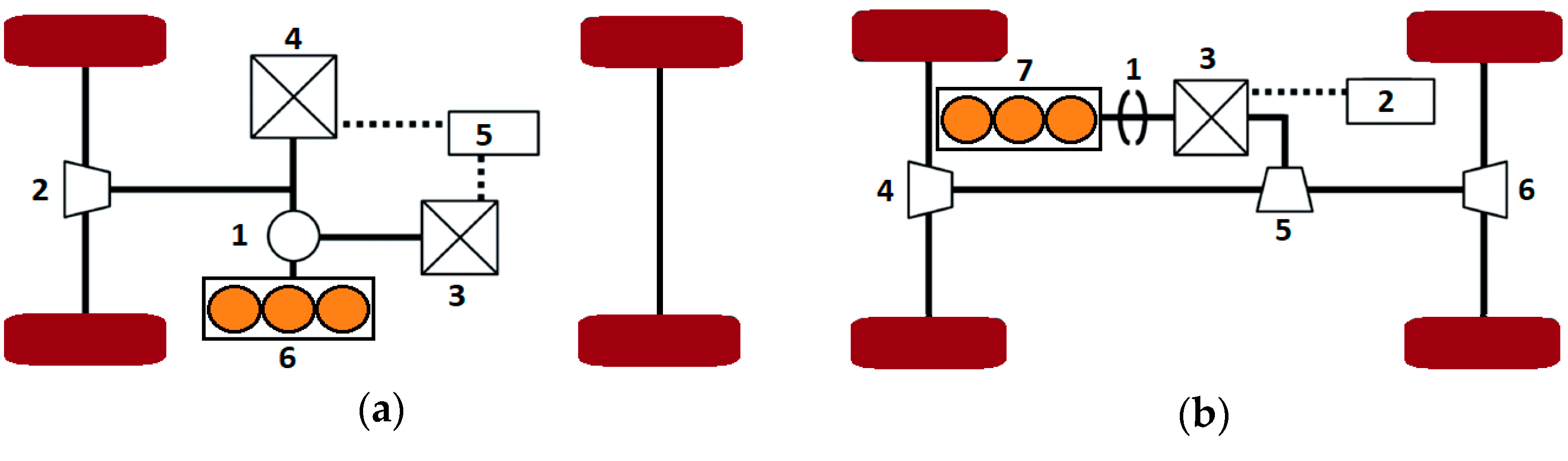
1.1. The Configurations of Hybrid Vehicles

Hybrid vehicles by type of power transmission are divided into:
  • Series hybrid—the ICE drives a generator that powers an electric motor (EM) connected to the drive wheels; the ICE is not mechanically linked to the drive wheels [17,18,19];
  • Parallel hybrid—an EM and an ICE are arranged to power the vehicle either individually or together [20,21,22];
  • Power-split hybrid—in a power-split hybrid drive, there are two power sources: EM and ICE; the power from these two sources can be shared to drive the wheels via a power split device; the ratio can be from 100% for the CE to 100% for the EM, or anything in between; the ICE can act as a generator charging the batteries [23,24,25,26,27].
Hybrid vehicles are also divided according to the degree of electrification of the power unit:
  • Micro-hybrid—cars with an ICE with a start–stop system [28];
  • Mild-hybrid—cars with an ICE equipped with an electric machine allowing one to stop the engine whenever the car is coasting, braking, or stopped, yet also to restart quickly [29];
  • Full-hybrid—a vehicle that can run on only the engine, the batteries, or a combination of both [30,31,32];
  • Plug-in hybrid—full hybrids that are able to run on battery power; they offer greater battery capacity and the ability to recharge from the grid [33,34].
Yang et al. [35] reviewed the electrified powertrains developed in the North American automotive industry. The vehicle categories depended on various powertrain configurations and electrification levels.
Different configurations of hybrid cars were discussed, inter alia, in [36]. The operation of full hybrids (FHEVs) is based on the independent use of a combination of ICE- and EM-powered batteries. The FHEVs’ batteries are recharged by running the ICE instead of by plugging it in. The operation of mild hybrids needs an all-time parallel drive from an EM and ICE. PHEVs require plugging into the mains to fully recharge their batteries. PHEVs can only drive in electric mode.
The mentioned three hybrid types utilize the maximum available electric portion of the drivetrain without weakening performance. Such a drive strategy allows for a decrease in emissions and an enhancement of fuel efficiency due to the lack of emissions from the EM and its higher efficiency compared to a combustion engine. Contrarily, high-performance hybrids utilize their EMs to maximize their performance, rather instead of their efficiency and eco-friendliness. FHEVs use regenerative braking, start–stop operation, the Atkinson Cycle, and continuously variable transmission (CVT) to improve fuel efficiency. They can operate in series mode, parallel mode, or all-electric mode. Mild hybrids use stop–start and regenerative braking. They can operate only in parallel mode. PHEVs use all the technology of FHEVs but usually have a larger capacity battery that is pluggable into the mains. They also have a higher drive range in all-electric mode than the average FHEV.
Oleksowicz and Burnham [37] reported a power split full hybrid with a front-wheel drive system (Figure 2a) and parallel full hybrid with an all-wheel drive system (Figure 2b).

1.2. Tests of Hybrid Vehicles

As reported in [38], applying standardized dyno methods to HEVs is problematic. The earlier HEV test procedures (standard SAEJ1711) were utilized by the Environmental Protection Agency “for the purposes of familiarization only and not to simulate a certification process”. Such procedures were hardly accepted due to the necessity of knowledge of the vehicle’s response to the test cycles or due to long terms. The California Air Resources Board (CARB) developed its own HEV test procedure for certification, following the SAE procedures and/or the EPA’s selection of test procedures.
The HEV’s reversible energy storage system often caused problems related to accounting for continued utilization of off-board electrical energy and to the transient energy utilization in hybrid operation.
The Argonne National Laboratory developed the Advanced Powertrain Test Facility, comprising tests carried out with OEM HEVs for the Japanese and the US models. ANL pursued the development of test procedures while studying OEM and prototype HEVs. ANL used some of the basic concepts developed in J1711 drafts, with a few procedures developed at various competitions. Accepted vehicle descriptions needed careful consideration for each automobile’s driving strategy and manipulations of the battery’s state-of-charge between test cycles to reach proper battery-use trends. Each test procedure had to allow for the comparison of mileage and emissions rates effects of HEVs with those of common cars by satisfying the test procedure inputs. ANL authorized the APTF predestined to testing and model validation of complex automobile solutions. They utilized the measured economy and emissions from engines and vehicles. Particularly, they investigated HEV powertrains and automobiles for assessment and model validation in DOE’s systems analysis group. It was found that multiple engine on/off operations during a test cycle can cause measurement troubles. The proposed ANL HEV testing methods are based on rigorous hybrid mode description. The emissions measurement systems providing repeatable measures for SULEV vehicles should allow for on/off engine operation.
According to [39], the known New European Driving Cycle (NEDC), used since the 1980s, was replaced by the better Worldwide Harmonised Light Vehicle Test Procedure (WLTP).
Fly [40] reported that in order to determine the range of a plug-in hybrid car without switching the engine on (so-called “all-electric range”), in the United Kingdom and EU, the Worldwide harmonized Light-duty vehicles Test Procedure (WLTP) is used.
Marignetti et al. [41] developed a tester for half a bus, reproducing the real slope, adhesion conditions, and weather conditions during a driving cycle.
In VTT’s emission laboratory in Finland, Figenbaum and Weber [42] studied two PHEVs on their power engagement, CO2 emission and locally polluting emissions, at +23 and −7 °C and in various drive cycles, such as NEDC, Artemis Urban, and Helsinki-city test, including in drive modes. They found that the CO2 emission of these vehicles was decreased by 30–50%, depending on automobile arrangement, and local pollution emissions were much lower compared to those of internal combustion engine vehicles (ICEVs). They observed however, for these vehicles, substantially more CO2 emission and power engagement than the unachievable type-approval values, for example, driving in cold zones under heavy loads with an empty battery.
Cubito et al. [43] analysed the effect of different driving cycles and operative conditions on CO2 emissions and on power control strategies of a Euro 6 HEV using fragmentary information obtained from the dyno tests. The automobile was studied for various start battery SOCs, ranging from 40% to 65%, and engine coolant temperatures from −7 to 70 °C. They found that changing test conditions from NEDC to WLTC caused a significant decrease in the electric drive and caused about a 30% enhancement of CO2 emissions. However, as the specific energy requirement of WLTC is about 1.5 times that of NEDC, the EMS strategies of the studied vehicles can allow one to obtain even greater real effectiveness levels than those of the NEDC and the effectiveness of HEV technology in decreasing CO2 emissions.
Cheng and Lai [44] proposed a robust evolutionary computation method called a “memetic algorithm (MA)” to allow one to obtain the best control parameters in parallel HEVs. The method was successfully utilized in the NEDC, Federal Test Procedure (FTP), Urban Driving Cycle + Extra-Urban Driving Cycle (UDC + EUDC), and Urban Dynamometer Driving Schedule (UDDS) to find their optimal control parameters.
Several kinds of tests were developed for determining the emissions of hybrid vehicles; however, the current and therefore developed WLTC test is of the greatest importance. The results of the older tests can be compared with those obtained from the WLTC, but this often requires introducing correction factors for the influence of the test conditions.

1.3. Research on Hybrid Vehicles

Many research studies on various hybrid vehicles are reported in the literature.
Francfort and Slezak [45] reported that the Department of Energy’s Field Operations program started testing of advanced-technology vehicles (ATVs) to obtain information on such vehicle performance necessary to optimally place them into fleet missions. The tests were carried out with one or more methods—baseline performance, accelerated reliability, and fleet testing. The program initiated the additional testing on neighbourhood and urban EVs, as well as on HEVs and hydrogen-powered vehicles.
Karner and Francfort [46] reported that the Advanced Vehicle Testing Activity (AVTA) program investigated full-size EVs, urban EVs, neighbourhood EVs, and hydrogen ICE-powered vehicles. The AVTA program carried out baseline performance, battery benchmark and fleet tests of HEVs and PHEVs.
FEV [47] developed a system engineering approach comprising the synergetic combination of testing, simulation and design assessment necessary in the concept phase of HEV development.
Li et al. [48] developed a heavy-duty hybrid power train dynamic tester. The latter utilized the technology of the common engine dyno and high dynamic AC frequency conversion dynamometer. The tester allowed for the mapping of a near-real road environment for a hybrid power train of the vehicle and different coupling structures of the hybrid power train. The tester allowed for the implementation of various vehicle performance tests, including power performance, energy economy, special hybrid function, etc.
Demuynck et al. [49] studied the real driving emissions (RDE) performance of a Euro 6b C-segment PHEV, comprising a direct injection gasoline (GDI) engine. The vehicle was investigated for various driving modes and initial battery SOCs. Some tests were duplicated with a gasoline particulate filter (GPF) placed in the exhaust line of the vehicle. The on-road test route and PEMS equipment were in accordance with the European RDE procedure (valid from September 2017). All data obtained are within the RDE boundary ranges. The RDE tests were also conducted on a dyno. The so-called “severitized” RDE trip differed from the reference RDE trip on the road, with the simultaneously enhanced vehicle accelerations and dyno load driving at 0 °C ambient temperature. All measured on-road NOx and PN emissions were below the Euro 6d not-to-exceed (NTE) limit. Even near to the RDE boundary, NOx emissions were under the RDE limit of 90 mg/km. PN emissions reached 3·1012 1/km during the OEM exhaust tests but decreased under the Euro 6d NTE limit of 9·1011 1/km with the GPF applied. Various sets of driving mode and initial battery SOC have a small effect on pollutant emissions. The urban RDE NOx emissions of this vehicle were the highest in “electric” mode, with the battery SOC below 100%. This was due to a cold start of the ICE in the middle of the RDE trip.
Campino et al. [50] studied the energy performance of PHEVs, based on road tests and under the RDE test, concentrating on the management system of the two energy sources present and varying the level of battery charge at the start of the test. They utilized a VSP parameter-based methodology, enabling the load state approximation according to the vehicle’s operating mode, changing between the three modes according to the conditions at the time in question, and prioritizing the EM when the battery SOC was at maximum. They found that PHEVs allowed for better electricity management due to the diversity of external or internal charging sources. This resulted in higher efficiency and versatility than conventional hybrids and in lower fossil fuel consumption and exhaust emissions.
Nazir et al. [51] proposed an adaptive nonlinear control strategy for the energy control of a polymer electrolyte membrane fuel cell and supercapacitor-based HEV.
Nguyễn et al. [52] proposed a real-time optimization-based torque distribution strategy for a parallel hybrid truck, allowing for minimal engine fuel consumption while ensuring a sustainable battery charge.
Wu et al. [53] developed a full-scale computer model FC/supercapacitor (SC) hybrid for performance studies on a hybrid propulsion system.
According to [54], through the use of hybrid vehicles, fuel consumption can be reduced. In the review, the different hybrid configurations, with a serial architecture and different strategy logic or with vehicle management units, were discussed. The role of simulations providing guidance on the best arrangement and the role of information on the component to be used were both emphasized.
Solouk and Shahbakhti [55] studied fuel economy of a reactively controlled compression ignition (RCCI) engine included in a series hybrid electric vehicle (SHEV) arrangement. They found a 13–14% fuel consumption decrease by using an RCCI engine. Such a fuel consumption was increased to 3% compared with a modern CI engine, while NOx emissions were clearly lower. The RCCI engine allowed for lower fuel consumption in more aggressive driving cycles.
Mocera and Somà [56] compared the performance between an agricultural tractor and its analog with a hybrid architecture. They used a set of tasks of an orchard tractor to determine the input signals of two models: diesel and hybrid electric arrangement.
Reported experimental and numerical (simulation) research studies were conducted for various realizations of hybrid drives in cars, trucks and tractors, particularly in terms of achieved power, fuel economy and emissions.

2. Emission of Hybrid Vehicles

Recently, the emissions of HEVs have become one of the most important areas of investigation. Karabasoglu and Michalek [57] compared the potential of hybrid, extended-range PHEVs, and BEVs to limit the lifecycle of GHG emissions under various scenarios and simulated driving conditions. They found that, depending on driving conditions, HEVs and PHEVs can decrease lifecycle emissions by 60% and costs by up to 20% in comparison to conventional vehicles. In contrast, under highway test conditions, electric vehicles provide insignificant emissions weakening at higher costs. Frequent stops of conventional vehicles increased their lifecycle emissions three-fold and costs by 30%, while aggressive driving decreased the all-electric range of PHEVs by up to 45% in comparison to the milder ones. Average lab-test vehicle efficiency estimates were found to be incomplete due to the following: (1) efforts to promote adoption of HEVs and PHEVs should be dedicated to urban drivers vs. highway drivers; (2) EVs act better on some drive cycles than others; thus, non-representative tests can negatively bias the acceptance of hybrid vehicles.
According to [58], during an entire lifetime (including emissions-generating fuel or electricity), a new PHEV from 2020 can emit about 28 tonnes of CO2, which is somewhat less than a conventional HEV (33 tonnes). A conventional petrol or diesel automobile can emit 39 and 41 tonnes, respectively. A new BEV can emit about 3.8 tonnes from the electricity utilized during an entire lifetime. CO₂ average emissions from PHEVs are 2.5 times higher than from the tests that the manufacturers show (120 g instead of 44 g of CO₂ per kilometre). Tong et al. [59] found that a BEV powered with natural gas-based electricity exhibited around a 40% decrease in LCA emissions in comparison to a conventional ICE. Despite the more common practice of producing vehicles with new hybrid systems, some manufacturers convert their classic models into HEVs. Such a transformation needs the design of a proper controller, usually using vehicle simulations. The controller under design should be adaptable to the used engine type and battery type in the simulation [60].
Several simulation software packages were developed intentionally for HEVs. Such simulation tools allowed for the prediction of vehicle fuel economy, emissions, acceleration, and grade sustainability. The mentioned tools comprised Matlab/Simulink based on tan advanced vehicle simulator [61], a hybrid vehicle evaluation code [62], CarSim [63], SIMPLEV [64], CSM HEV [65], and Elph/V-Elph [66].
Taymaz and Benli [67] developed a programme for road simulations for HEVs. Such a programme allowed for calculations of acceleration, fuel consumption and exhaust emission. They numerically studied a conventional automobile modified to a mixed hybrid version. They found that the mixed hybrid automobiles had close performance values with low fuel consumption.
The emissions of hybrid vehicles strongly depend on applied control strategies.
The fuzzy logic control is predestined for the control of HEVs as a suitable method for such non-linear systems with time-dependent components [68,69]. Kheir et al. [70] developed a generalized fuzzy logic controller (FLC) to optimize fuel economy and reduce the emissions of HEVs with parallel configurations.
Orecchini et al. [71] studied two conventional ICEs, two hybrid electric vehicles, and one pure electric powertrain through determination of their power engagement and CO2 emissions, which were based on fuel consumption determined during driving on the roads in Rome. The authors found a significant decrease in power engagement and CO2 emissions of hybrid electric powertrains compared to conventional ones. Differences were also found between the power engagement values characteristic for real driving and those derived from the NEDC and WLTC homologation cycles. For the WLTC procedure, these differences were smaller than for NEDC, and in both cases, they differed significantly for powertrains such as SI ICEs, HEVs and BEVs, depending on the degree of vehicle electrification.
Capata and Tatti [72] numerically simulated a hybrid series vehicle with a micro gas turbine instead of a heat engine in both urban and suburban cycles, to determine their effect on performance, the battery SOC, the operating points of the microturbine, the input and output energies for individual components, and fuel economy. The simulated vehicle was compared with the Toyota Yaris Hybrid in relation to performance, fuel consumption and emissions. The latter was also compared with the values set by the EURO 6 standard.
To optimize parallel HEVs, Shivappriya et al. [73] proposed a fuel consumption and exhaust emissions control strategy based on a combined Modified Artificial Bee Colony algorithm (MABC) with the SQP approach. Qiao et al. [74] proposed a control algorithm for the energy management system (EMS) of HEVs. A composite objective function was set up using the equivalent consumption minimization strategy, and suitable simulation models were designed. In order to minimize vehicle CO2 emissions, Bozza et al. [75] used a calibration method for two-stage supercharging of an ultra-low emission SI pre-chambered engine equipped with variable valve timing (VVT) and an E-compressor connected in series with a turbocharger to provide the appropriate level of supercharging necessary for ultra-low emission operation.
Frey et al. [76] proposed a method for quantifying the real driving, efficiency, and exhaust emissions of PHEVs. They found that, compared to conventional light duty ICE vehicles, the PHEVs operating in charge-depleting (CD) mode had higher performance and lower emissions for a wide range of power-generation fuel mixes. However, PHEV efficiency and emissions highly varied, worsening especially on cold starts.
Konečný et al. [77] confirmed the positive effects of the substitution of diesel buses with hybrid-driven and electric-driven ones, in the urban public transport fleet, on its emissions production in the city of Žilina. They proposed a method for the determination of direct and indirect emissions. The regression functions-based indirect emissions factors (WtT, well-to-tank) together with the direct TtW (tank-to-wheels) emission factors allowed for the evaluation of environmental effects, such as energy source, fuel, powertrain and type of operation, for the various vehicle types. The emissions were determined using simulation software based on the Handbook of Emission Factors for Road Transport.
Xiong et al. [78] compared lifecycle efficiency and GHG emissions of BEVs and PHEVs powered with LFP and NMC batteries. They analysed the sensitivity of electricity generation mix, lifetime mileage, utility factor, and battery recycling. BEVs were less emission intensive than PHEVs, and the energy use and GHG emissions of a BEV were about 3% (NMC) to 9.6% (LFP) and 16% (NMC) to 26.3% (LFP) lower, respectively, compared to those of a PHEV.
Finesso et al. [79] developed an optimal design toolbox for HEVs and applied it to a compact vehicle and a small and a medium SUV for two separate power-split hybrid systems with diesel engines. According to [80], the emission laboratory at VTT in Finland on commission from TØI allowed for studies on the classical and hybrid vehicles’ full emissions and power engagement in a climatic chamber. A dyno allowed for simulations of the road conditions. The vehicles were driven in various drive cycles during which the emissions were measured. The climatic chamber, cooled to a temperature of −7 °C, was used in EMROAD.
Feinauer et al. [81] postulated to increase the scope of NOx and PN measurements, as they found that cold start of the plug-in vehicle engine significantly increased the emissions of these components, especially in urban conditions. The uncertainty of these measurements also increased (scatter within 50%), which consequently led to inconclusive results. Kazemzadeh et al. [82] showed that electric and plug-in vehicles, in the overall balance, reduced the emission of airborne particulate matter (PM2.5); however, increasing energy intensity and fossil fuel consumption worsened it.
Jung [83] states that in road tests, PHEVs show reduced fuel consumption ranging from 22% to 49% in addition to weather conditions and driving mode (charging and discharging), which is noticeable when driving the vehicle in urban conditions. Other conclusions were identified by Wróblewski et al. [84], where the authors found a dependence of energy intensity on driving technique. The study confirmed longitudinal acceleration and torque produced during the electric drive. This allowed for an estimation of the impact of driving on power engagement.
The reported studies on the emissions of hybrid vehicles were conducted experimentally and numerically. The latter were often focused on the control algorithms for such vehicles. The experimental ones related to the measurements of CO2, CO, NOx, HC and PN emissions. but the published results were obtained by various methods or tests. Experimental tests of various cars should now be continued using the latest WLTC test. However, in order to limit the influence of various factors making it difficult to compare results from different emission measurements, the latter should be compared with the previous ones within the vehicles of one manufacturer. The goal of the present study was to investigate the effect of the type of hybrid drives, namely plug-in and HEV, used in vehicles of one manufacturer on the emissions of these vehicles.

3. Materials and Methods

3.1. Research Methodology

Comparative emission tests for HEV and plug-in hybrid vehicles were carried out for two selected vehicles (the most popular in Poland). Characteristics of the vehicles are presented in Section 3.2. Exhaust emissions measurements and further comparisons were made in the WLTC homologation test on a chassis dynamometer (Section 3.3) and in real traffic conditions (Section 3.4). The exhaust emission measurement apparatus used for the chassis dynamometer and road testing is described in the relevant sections.

3.2. Vehicles Tested

Two hybrid vehicles were tested, the first of the HEV type and the second of the plug-in type. Both vehicles were equipped with gasoline engines. The vehicles were offered for sale in two power unit variants: HEV and PHEV. In Poland, they are one of the most popular models: in 2021, about 30,000 models of the brand’s hybrid vehicle were sold, of which about 10% were PHEV. Some characteristics of the vehicles are given in Table 1 and [85].

3.3. Laboratory Test

The WLTC driving cycle was chosen for the measurement of hybrid vehicle emissions. The scheduled velocity for plug-in hybrid vehicles is presented in Figure 3a, and for HEV is presented in Figure 3b. They are practically the same.
The exhaust emission tests were performed in the WLTC tests, which were carried out on a chassis dynamometer. The emissions of individual harmful compounds (including CO2, CO, NOx, THC and PN) were measured in accordance with the European Union procedure. The same fuel was used for the tests, i.e., gasoline containing 5% of biocomponents. The resistance to motion of the chassis dynamometer was adjusted to the road load, in accordance with the regulations that require such a procedure, especially in the case of hybrid vehicles that can move in electric mode, and the dynamometer in the energy recovery mode.
Research on the impact of the type of hybrid vehicle in type-approval tests on the emission of exhaust gases was carried out on a chassis dynamometer in accordance with the methods valid in Europe. Both the typical (for measurements using the “measurement bags” method) and the extended (for modal analysis) apparatuses for measuring the emission of harmful compounds in exhaust gas were used in the tests. The dynamometer was driven by an AC asynchronous motor located between the rollers. In front of the chassis dynamometer, a fan was set up to cool the vehicle. This fan simulates the air flow from 0 to 125 km/h, proportional to the speed of the car running on the chassis dynamometer. The laboratory was equipped with a HORIBA exhaust gas sampling and analysis test kit. HORIBA consists of a CVS–CFV exhaust gas sampling system with a dilution tunnel and a set of MEXA exhaust gas analysers for the simultaneous measurement of exhaust gas compounds (CO, CO2, NO, NO2, THC). The sampling bags for the diluted exhaust gas samples and the dilution air samples were insulated to prevent sample condensation. The exhaust gas sampling and dilution system consisted of two independent lines: one for spark ignition engine cars with an exhaust–air mixing tee, and one for compression ignition engine cars with a dilution tunnel. The HORIBA 2000-SPCS meter allows the particulate matter in the diluted exhaust to be counted at a frequency of up to 10 Hz. The unit allows a wide range of exhaust dilution rate selection to provide compliant (CPC ≤ 10,000 1/cm3) results for cars with different aftertreatment systems.

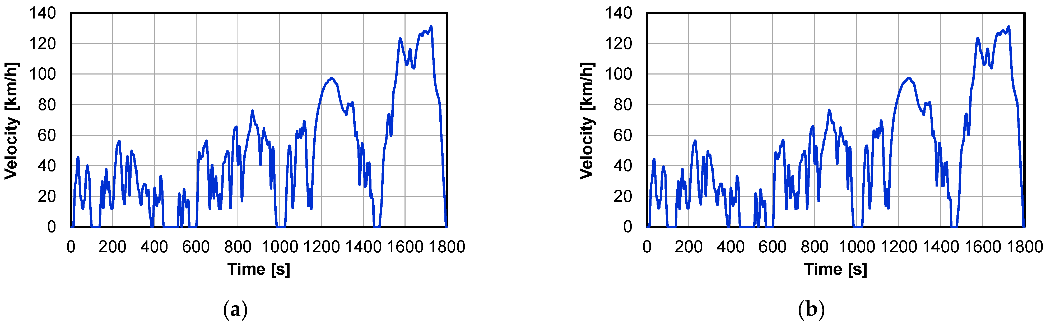
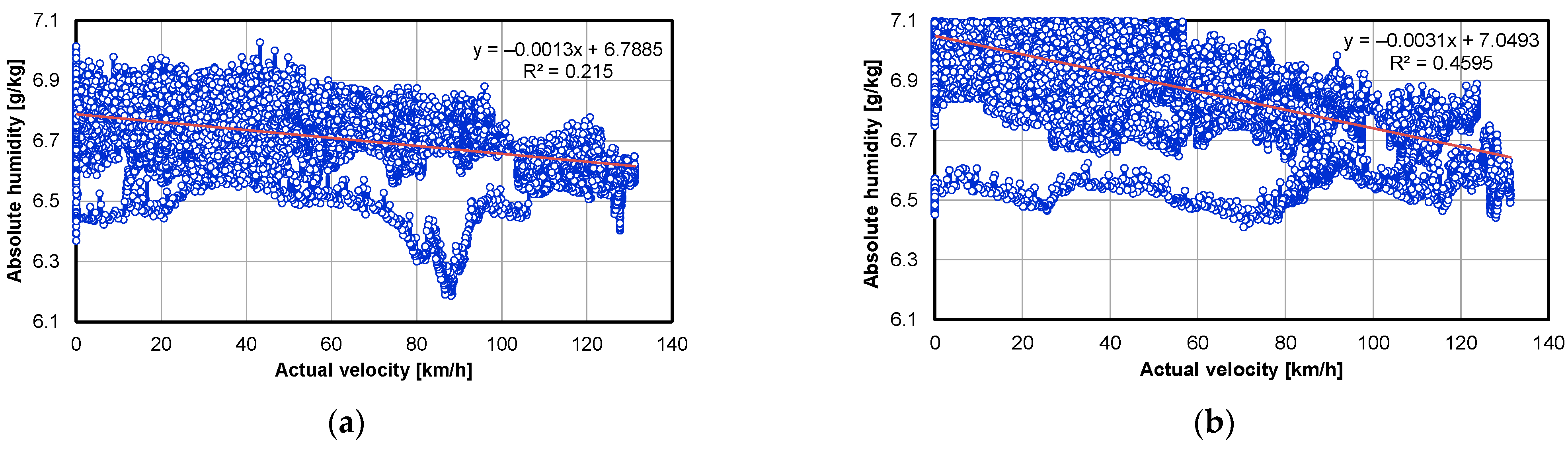
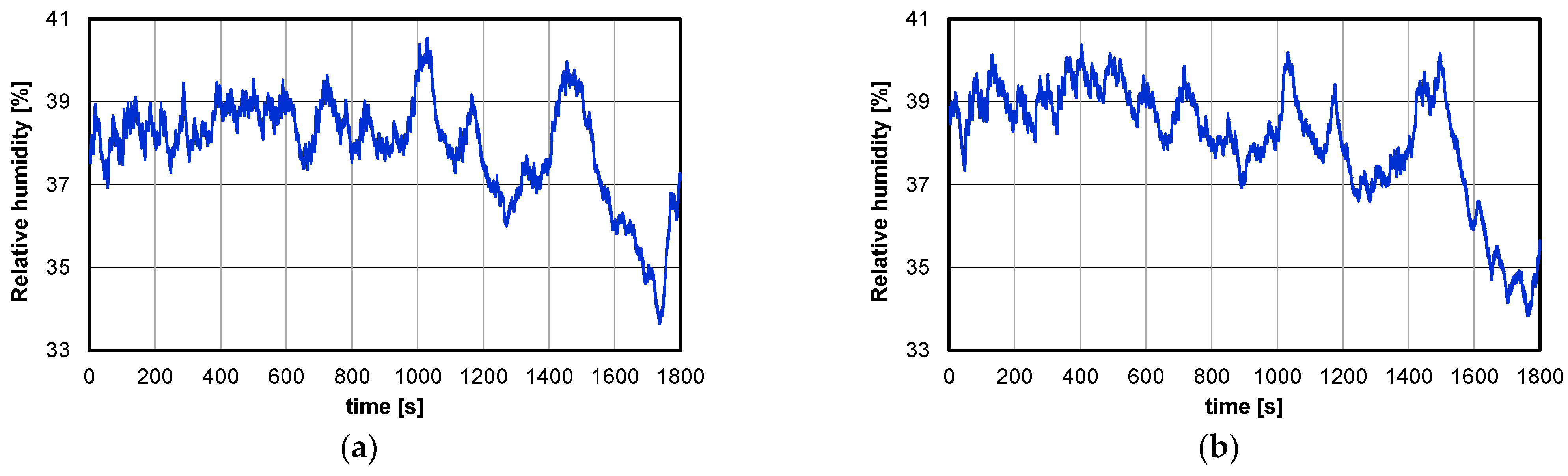
3.4. Real Driving Emission

The RDE test includes driving in urban, rural and motorway conditions. The duration of the test is within the permissible range, i.e., from 90 to 120 min. The average speed (including stops) shall be between 15 and 40 km/h. The test route has been designated in accordance with RDE requirements and is divided into 3 sections: urban, rural and motorway (Table 2). The driving distances, shares of individual portions of the test and test conditions have been chosen such that they meet the requirements described in the Commission Regulations 2016/427 [86], 2016/646 [87] and 2017/1154 [88]. The total distance of the research route was approximately 100 km, the average velocity was about 44 km/h and the average test duration was about 108 min. A portable Semtech DS (Sensors, Ann Arbor, MI, USA) analyser was used for the research of exhaust emissions from the tested vehicles (Table 3). This system fulfils all European Union requirements regarding the measurement of gaseous emissions from LDV under real driving conditions.
For the measurement of particle diameters, a TSI Incorporated (Shoreview, MN, USA) analyser, EEPS 3090 (Engine Exhaust Particle Sizer™ Spectrometer), was used, which measured the discrete range of particle diameters (from 5.6 to 560 nm) based on their different electrical mobilities.

4. Results and Discussion

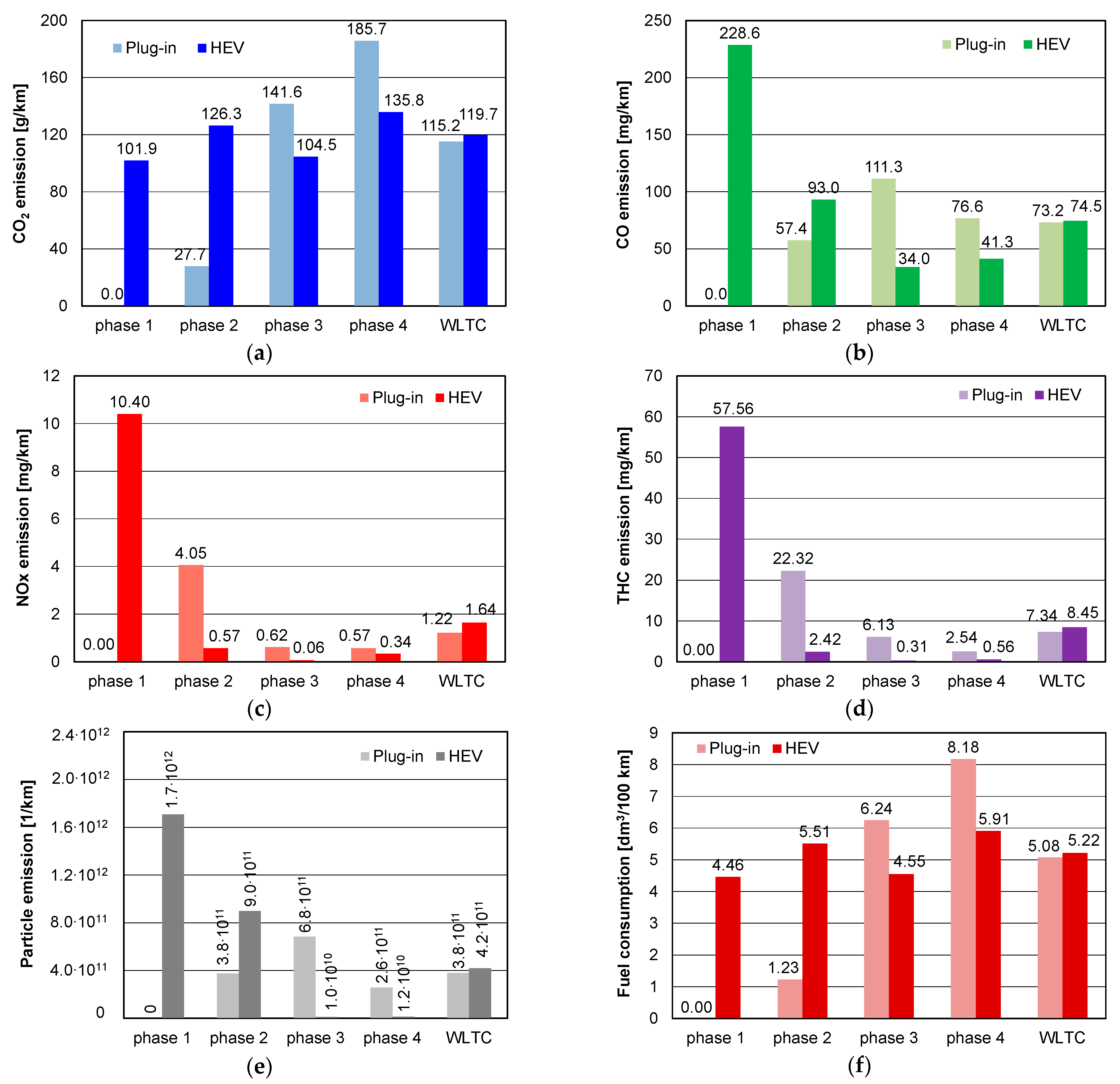
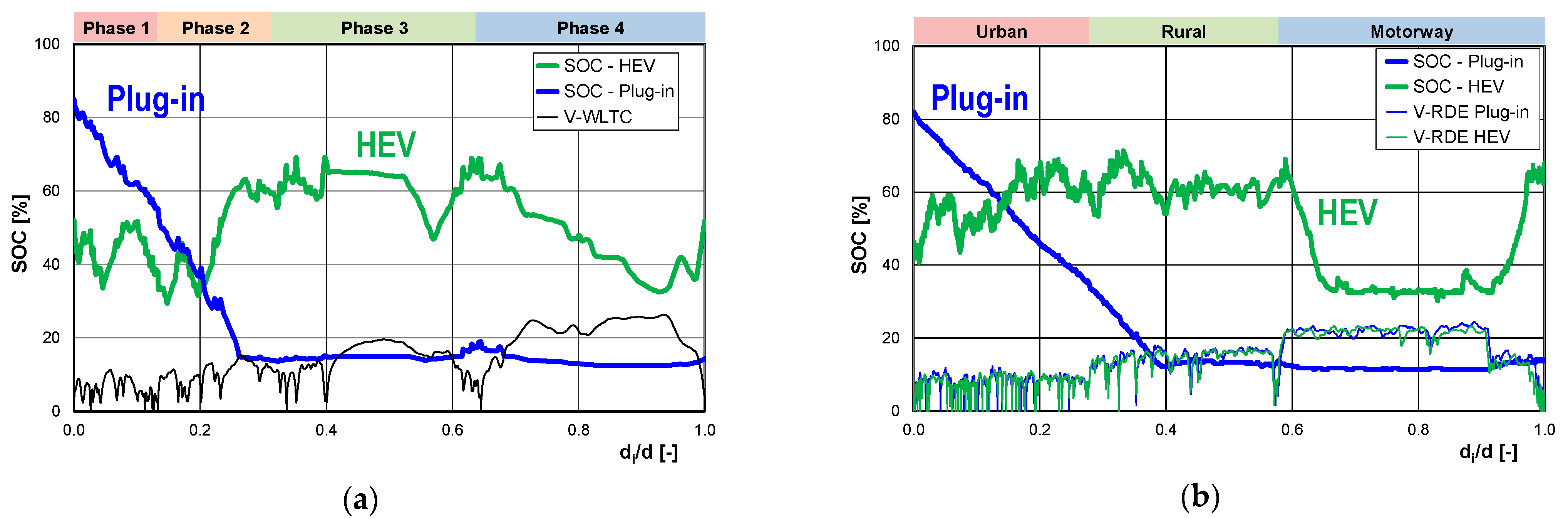
4.1. Results in WLTC

4.1.1. Test Conditions

The measured temperature of the dry air during tests is presented in Figure 4a for plug-in and in Figure 4b for HEV. The temperature in the case of the plug-in was lower by 1 K compared to that in the case of HEV, especially for the lower values of actual velocity, which resulted from conditions in the place where the dyno was located. The relation between the temperature of the air and actual velocity are shown in Figure 5a for the plug-in and in Figure 5b for HEV. In the case of HEV, the temperature increased 1.5 times more quickly with the increase in the actual velocity than in the case of the plug-in. The dispersion of temperature values decreased with the increase in actual velocity in both cases.
The absolute humidity during the tests is shown in Figure 6a for the plug-in and in Figure 6b for HEV. For the low velocity phase of the WLTC test, the absolute humidity in the case of the plug-in was lower by up to 0.5 g/kg compared to that in the case of HEV. It also resulted from the conditions in the place where the dyno was located. The relation between absolute humidity and actual velocity are shown in Figure 7a for the plug-in and in Figure 7b for HEV. In the case of HEV, the absolute humidity decreased twice as quickly as the increase in the actual velocity than in the case of the plug-in. The dispersion of values of the absolute humidity decreased with the increase in actual velocity in both cases.
The relative humidity during the tests is shown in Figure 8a for the plug-in and in Figure 8b for HEV. The relative humidity in the case of the plug-in was lower by 1–3% compared to that in the case of HEV. Such differences were higher for the lower velocities during the WLTC tests. It also resulted from conditions in the place where the dyno was located.

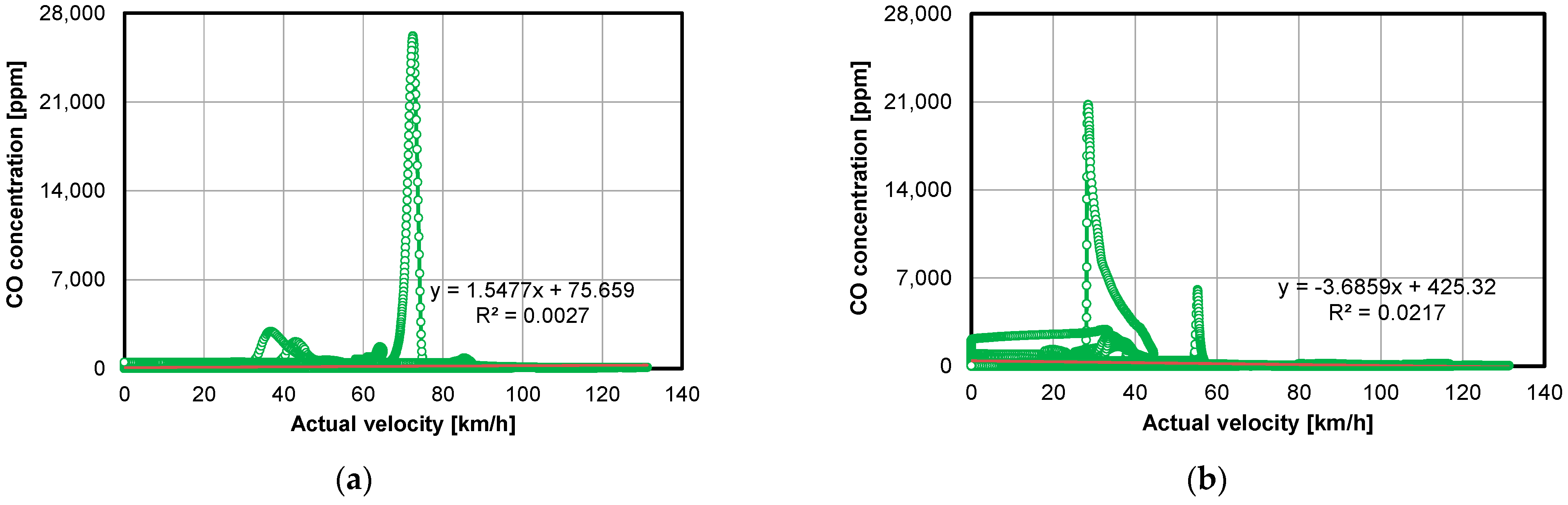
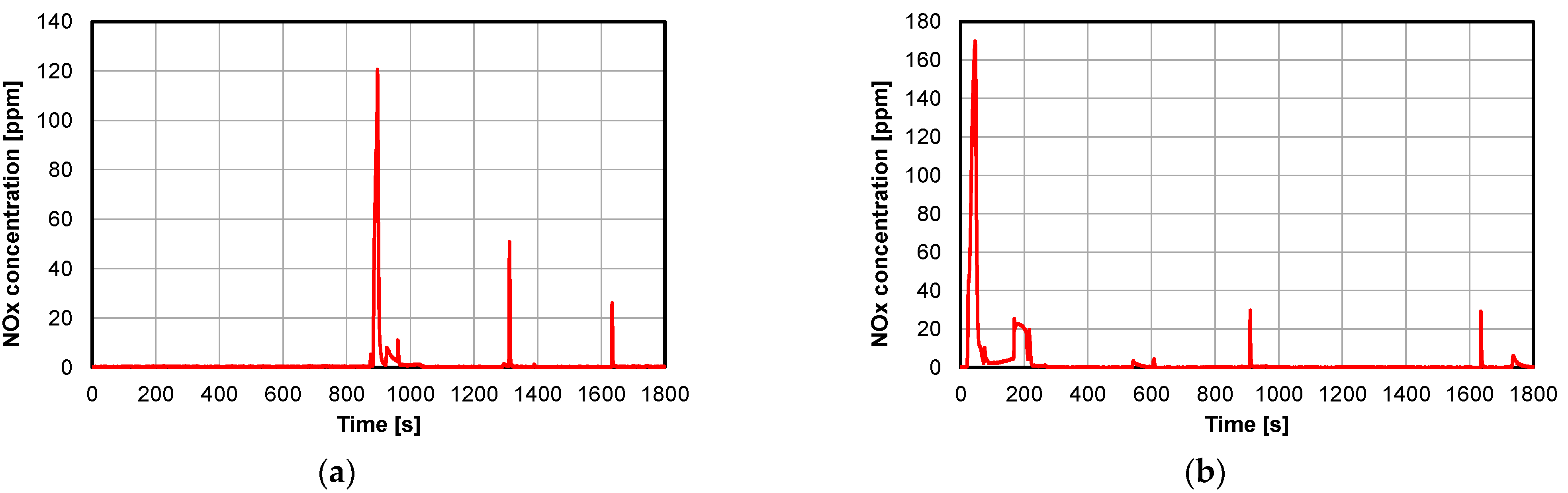
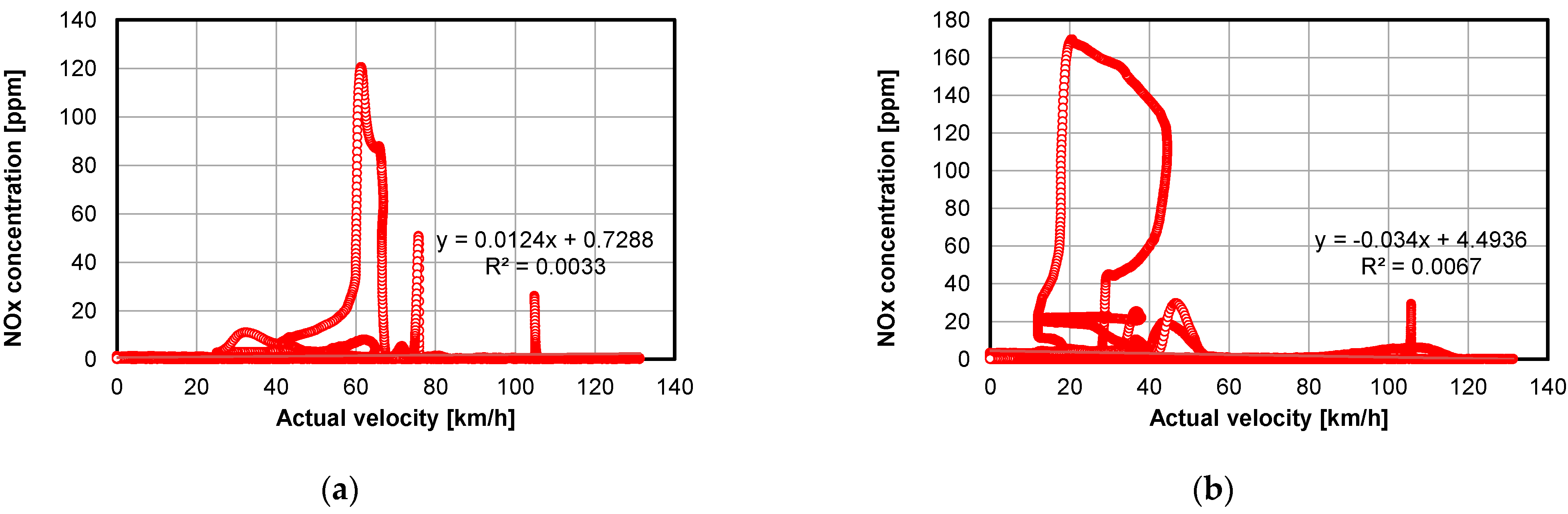
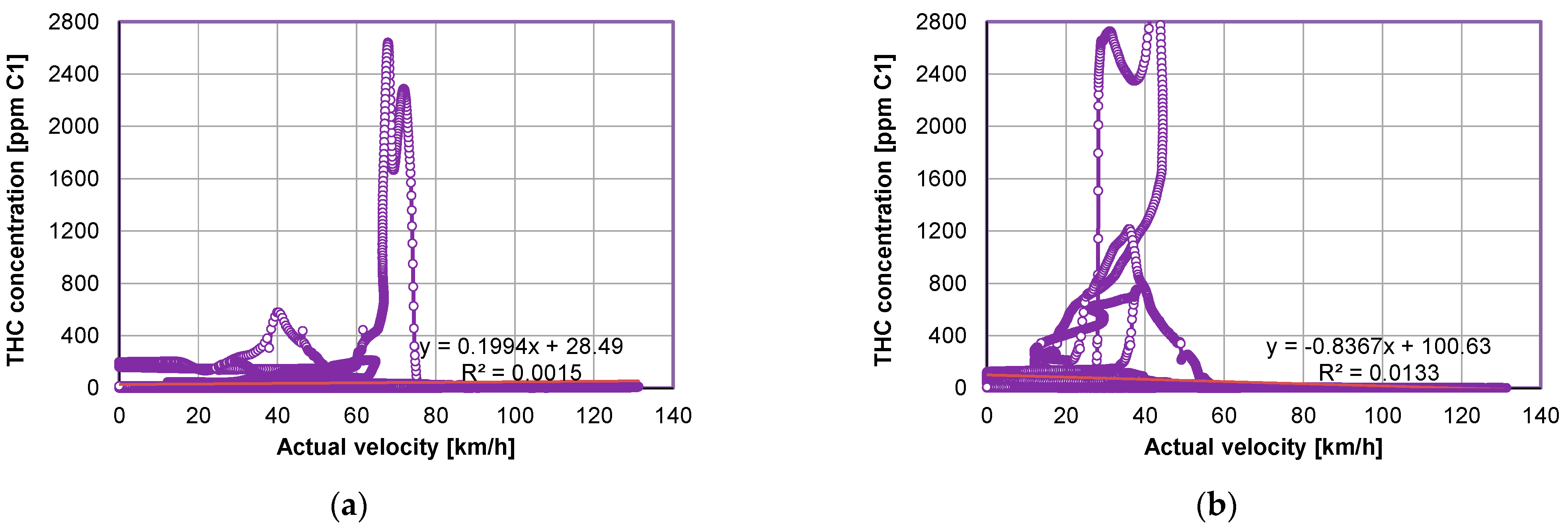
4.1.2. Measurement of the Concentration of Polluting Compounds

The CO2 content during the tests is shown in Figure 9a for the plug-in and in Figure 9b for HEV. In the case of HEV, the CO2 content oscillated around the level of 14% for most of the test. The higher changes occurred for smaller values of actual velocity, and occasional jumps to 5% were also visible. In the case of the plug-in, in the first half of the test, the CO2 content was equal to zero due to driving with EM. In in the second half, such a content oscillated around the level of 14%, with possible occasional jumps to 5%. The relation between CO2 concentration and actual velocity is shown in Figure 10a for the plug-in and in Figure 10b for HEV. In the case of the plug-in, the CO2 content varied between the levels of 0% and 14% for the values of actual velocity up to about 80 km/h, which was possible due to driving with EM or ICE. Such content stabilized on the level of 14% above 80 km/h, which was related to driving only with a combustion engine. In the case of HEV, most values of CO2 content were close to 14%; however, such content varied between the levels of 0% and 14% for values of actual speed below 30 km/h, varied between the levels of 6% and 14% for values of actual speed in the range of 30–120 km/h, and stabilized on the level of 14% above 120 km/h. This reflected driving with a competitive choice between the ICE and EM, with the latter being less involved as the actual velocity increased.
The CO concentration during the tests is shown in Figure 11a for the plug-in and in Figure 11b for HEV. The relation between CO content and actual velocity is shown in Figure 12a for the plug-in and in Figure 12b for HEV. In the case of the plug-in, such a concentration was equal to zero in the first half of the test due to driving with EM. In the second half of the test, the CO concentration varied between the levels of 0 and up to 3000 ppm, especially for actual velocity values in the range of 30–90 km/h. This was due to driving with a competitive choice between a combustion engine and electric motor. The sharp jumps observed up to 27,000 ppm related to the acceleration events that occurred during the test. In the case of HEV, the CO concentration clearly varied between the levels of 0 and about 3000 ppm for values of actual velocity below 60 km/h, which was related to driving with a competitive choice between a combustion engine and electric motor. In addition, in this case, the sharp jumps of CO concentration up to 21,000 ppm occurred due to acceleration events. Such jumps occurred even more often compared to the case of driving a plug-in with a combustion engine. Except for sudden jumps, in the case of the plug-in, the CO concentration slowly increased with the increase in the actual velocity up to 110 km/h and then stabilized, reaching several hundreds of ppm. This was due to an increasing, although somewhat disturbed, number of events of driving with a combustion engine. In addition, in the case of HEV, the CO concentration slowly decreased with the increase in absolute velocity values as observed from 60 km/h, which reflected the increased use of a combustion engine during driving.
The NOx concentration during tests is shown in Figure 13a for the plug-in and in Figure 13b for HEV. The relation between NOx concentration and actual velocity is shown in Figure 14a for the plug-in and in Figure 14b for HEV. In the case of the plug-in in the first half of the test, such a concentration oscillated with positive values around the level of 0 ppm due to driving with an electric motor. In the second half of the test, such a concentration varied between the levels of 0 and up to 10 ppm, especially for actual velocity values in the range of 30–90 km/h. This was due to driving with a competitive choice between a combustion engine and electric motor. The sharp jumps observed up to 120 ppm related to the acceleration events that occurred during the test. In the case of HEV, such a concentration clearly varied for values of actual velocity in the ranges of 10–60 and 80–120 km/h. The latter was due to driving with a competitive choice between a combustion engine and electric motor, but the former was affected by more factors, as there were three or four possible distinctive levels of NOx concentration for the same absolute velocity values. Except for the sudden jumps, in both cases, the NOx concentration slowly decreased with the increase in actual velocity, which reflected the increased use of a combustion engine during driving. The observed sharp jumps in such a concentration were higher by 20% in the case of the plug-in and by 70% in the case of HEV compared to the NOx concentration, reaching up to 100 ppm during the tests reported in [2]. Such tests were conducted using two different driving routes selected for a city and highway real-world driving conditions using HEV with a gasoline engine of 1.8 L displacement and a max power of 90 kW.
The THC concentration during the tests is shown in Figure 15a for the plug-in and in Figure 15b for HEV. The relation between THC concentration and actual velocity is shown in Figure 16a for the plug-in and in Figure 16b for HEV. In the case of the plug-in in the first half of the test, such a concentration was equal to zero due to driving with an electric motor. In the second half of the test, such a concentration varied between the levels of 0 and at least 200 ppm for actual velocity values below 70 km/h. This was due to driving with a competitive choice between a combustion engine and electric motor. The sharp jumps observed up to 2700 ppm related to the acceleration events that occurred during the test. In the case of HEV, such a concentration clearly varied for values of actual velocity below 60 km/h. This was not only due to driving with a competitive choice between a combustion engine and electric motor, but also to other factors, as there were three or four possible distinctive levels of THC concentration for the same absolute velocity values.
Similar to the case of CO concentration, except for the sudden jumps, in the case of the plug-in, the THC concentration slowly increased with the increase in the actual velocity up to 110 km/h and then stabilized, reaching several hundred ppm. This was due to an increasing, although somewhat disturbed, number of events of driving with a combustion engine. In addition, in the case of HEV, the THC concentration slowly decreased with the increase in absolute velocity values as observed from 60 km/h, which reflected the increased use of a combustion engine during driving.
The CO2 mass during the tests is shown in Figure 17a for the plug-in and in Figure 17b for HEV. In the case of the plug-in in the first half of the test, the CO2 mass was equal to zero due to driving with an electric motor. In in the second half, such a mass varied between the levels of 0 and 0.05 g for values of absolute velocity below 20 km/h. Above the latter value, such a mass varied between the lower level of 0.05 g and the upper one, in which the values increased in a disturbed and slowly oscillating-like manner with the increase in absolute velocity. Similar to the case of the plug-in in the second half of the test, the CO2 mass also varied in the case of HEV for values of absolute velocity up to 115 km/h. Above the latter, the mentioned lower level was of 0.1 g, and the mentioned upper level decreased in a disturbed, oscillating-like manner with the increase in absolute velocity. In both cases, it was not only due to driving with a competitive choice between a combustion engine and electric motor, but also to other factors, as there were three or four possible clearly distinctive levels of CO2 mass for the same absolute velocity values.
The CO mass during the tests is shown in Figure 18a for the plug-in and in Figure 18b for HEV. In the case of the plug-in in the first half of the test, the CO mass was equal to zero due to driving with an electric motor. In in the second half, such a mass varied between the levels of 0 and 0.2 mg for values of absolute velocity below 20 km/h. Above the latter value, such a mass varied between the lower level of 0 and the upper one, in which the values varied in a disturbed, oscillating-like manner with the increase in absolute velocity up to 90 km/h. Above the latter, the upper limit reached values of up 0.6 mg. The occasional jumps of such a mass up to 7.5 mg in the case of the plug-in were due to driving with a combustion engine, and they ended up at 9 mg in the case of HEV, which occurred due to acceleration events. In both cases, this was due to driving with a competitive choice between a combustion engine and electric motor. However, in certain ranges of absolute velocity values, it was also due to other factors, as there were three or four possible distinctive levels of CO mass for the same absolute velocity values.
The NOx mass during the tests is shown in Figure 19a for the plug-in and in Figure 19b for HEV. In the case of the plug-in in the first half of the test, such a mass oscillated with positive values around the level of 0 mg, also due to driving with an electric motor. In the second half of the test, such a concentration varied between the levels of 0 and up to 0.05 mg for actual velocity values below 20 km/h and between the levels of 0 and up to 0.03 mg for actual velocity values above 60 km/h. This was due to driving with a competitive choice between a combustion engine and electric motor. For absolute velocity values in the range 20–60 km/h, the mentioned upper limit varied in a complex manner, and it was affected by different factors, as there were three or four possible distinctive levels of NOx mass for the same absolute velocity values.
In the case of HEV, such an NOx mass varied between the levels of 0 and up to 0.03 mg; however, for values of actual velocity in the ranges of 10–60 km/h, the upper NOx mass limit reached much higher values and varied in a complex manner. The sharp jumps observed up to 0.12 and 0.17 mg in the plug-in case and in the HEV case, respectively, were related to the deceleration events that occurred during the test.
The THC mass during the tests is shown in Figure 20a for the plug-in and in Figure 20b for HEV. In the case of the plug-in in the first half of the test, such a mass oscillated with positive small values around the level of 0 mg, also due to driving with an electric motor. In the second half of the test, such a concentration varied between the levels of 0 and up to 0.03 mg for actual velocity values below 20 km/h. The upper mass level varied in an oscillation-like manner between the values of 0.03 and 0.05 mg for actual velocity values above 90 km/h. For actual velocities in the range of 20–90 km/h, the upper limit reached much higher values and varied in a complex manner. This was due to driving with a competitive choice between a combustion engine and electric motor. In the case of HEV, such a mass varied between the levels of 0 and up to 0.03 mg; however, for values of actual velocity in the range of 10–60 km/h, the upper THC mass limit reached much higher values and varied in a complex manner. The latter was also affected by many factors, as there were three or four possible distinctive levels of THC mass for the same absolute velocity values. The sharp jumps of THC mass observed up to 0.65 and 0.7 mg in the case of the plug-in was due to driving with a combustion engine, and in HEV case, respectively, was related to the acceleration events that occurred during the test.
Fuel consumption (FC) during the tests is shown in Figure 21a for the plug-in and in Figure 21b for HEV. In the case of the plug-in in the first half of the test, fuel consumption was equal to zero due to driving with an electric motor. In in the second half, fuel consumption varied between the levels of 0 and 0.0002 dm3 for values of absolute velocity below 20 km/h. Above the latter value, fuel consumption varied between the lower level of 0.0002 dm3 and the upper one, in which the values increased in a complex, slowly oscillating-like manner with the increase in absolute velocity. Similar to the case of the plug-in in the second half of the test, fuel consumption also varied in the case of HEV for values of absolute velocity up to 120 km/h. Above the latter, the mentioned lower level was of 0.0002 dm3, and the fuel consumption upper level decreased in a complex, oscillating-like manner with the increase in absolute velocity. In both cases, it was not only due to driving with a competitive choice between a combustion engine and electric motor, but also to other factors, as there were three or four possible distinctive levels of fuel consumption for the same absolute velocity values.
The particle number (PN) rates during the tests are shown in Figure 22a for the plug-in and in Figure 22b for HEV. In the case of the plug-in in the first half of the test, the PN rate was equal to zero. In the second half of the test, the PN rate varied between the lower and upper limits, due to driving with an electric motor, with relatively close values increasing with the increase in actual velocity. For the actual velocity values in the range of 20–60 km/h, the upper PN rate limit reached much higher values and varied in a complex manner with an increase in the actual velocity. In the case of HEV, the variations of PN rate were similar to those of the plug-in case in the second half of the test. The lower PN rate limit increased almost twice as quick with the increase in actual velocity compared to the plug-in case in the second half of the test. In both cases, the PN rate variations were due to driving with a competitive choice between a combustion engine and electric motor, but for the actual velocity values in the range of 20–60 km/h, and due to other factors, there were three or four possible distinctive levels of PN rate for the same actual velocity values. The PN variations were similar to the variations of PN rate in both cases of the plug-in and HEV. The PN in the plug-in case in the second half of the test could reach an even 20% higher peak value compared to the case of HEV. The average PN was equal to 3.79·1010 for the case of the plug-in and 4.02·1010 for the case of HEV.

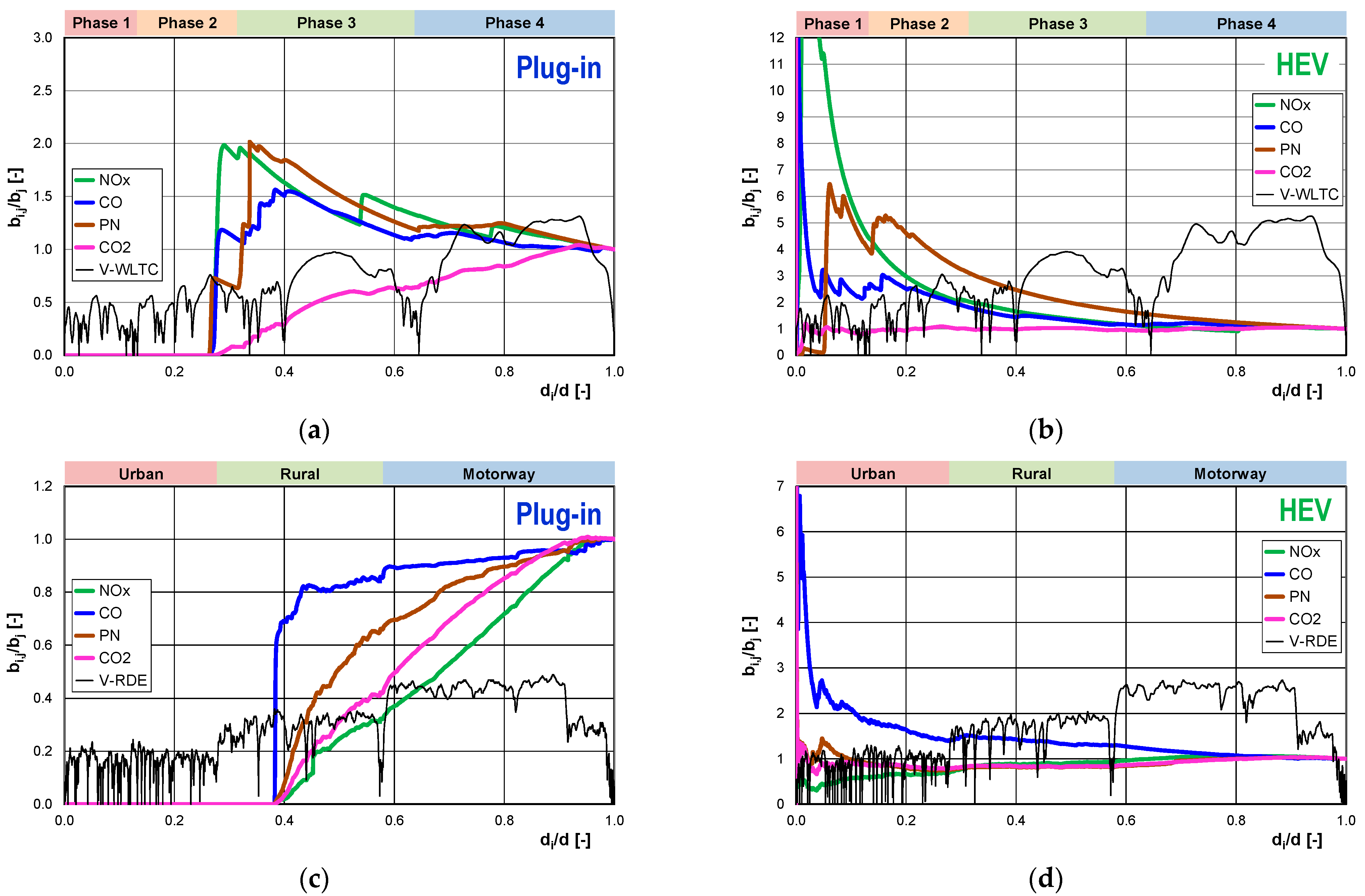
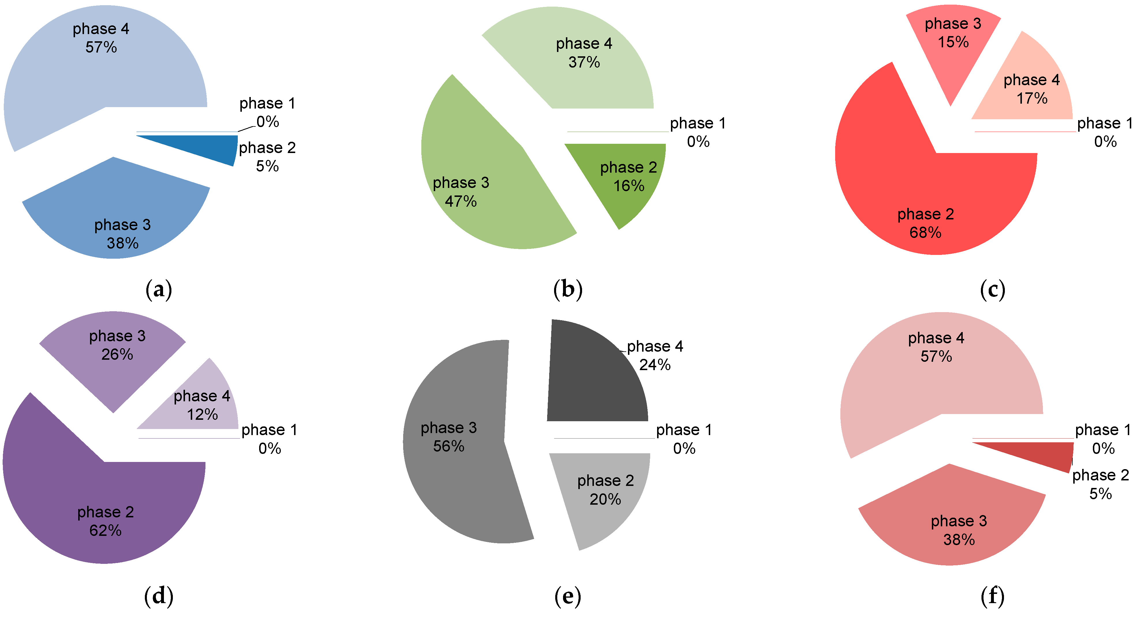
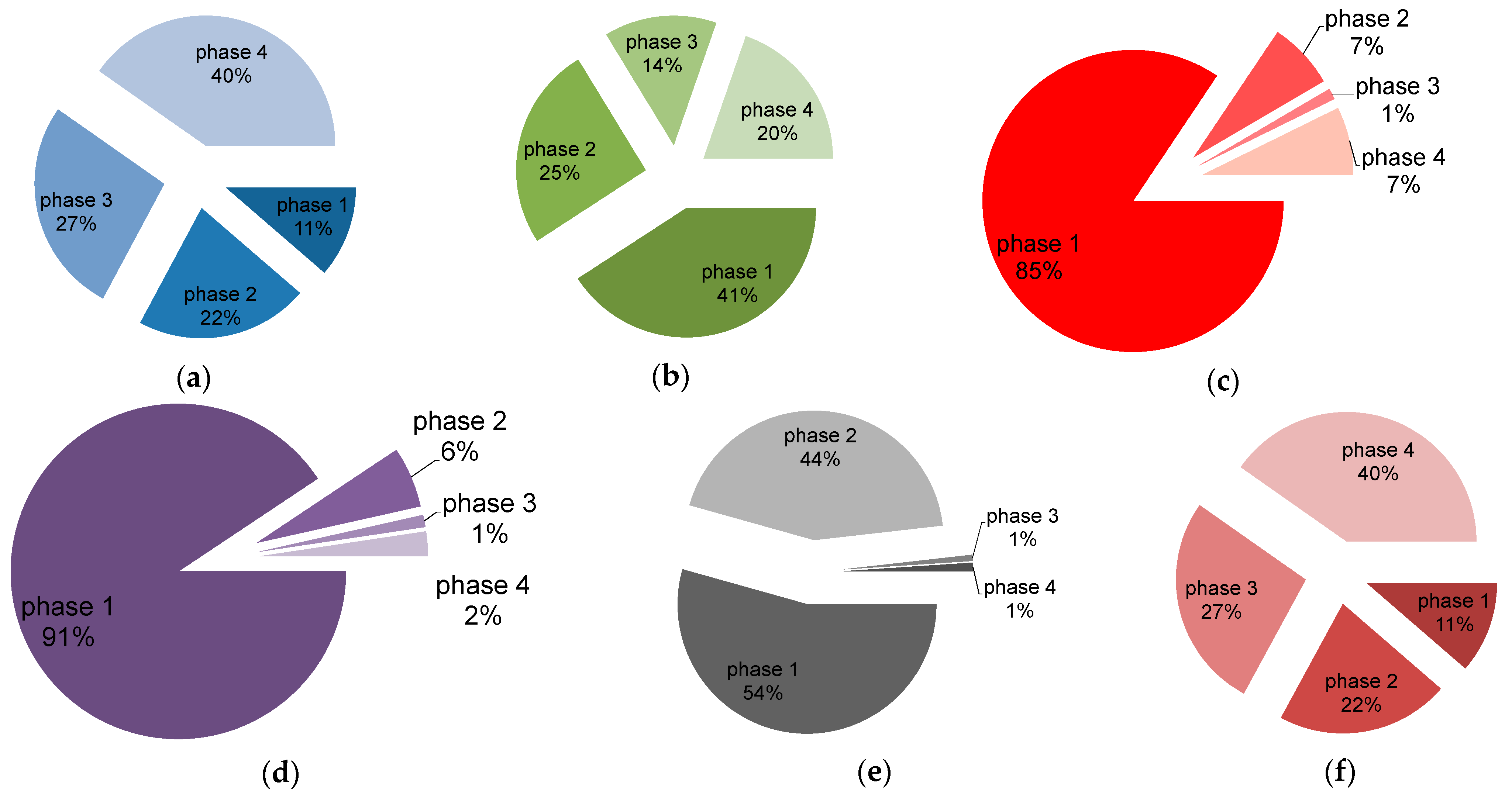
4.1.3. Comparison of Results in the Phases of the WLTC Test

The correlations discussed above describe the concentration and mass of pollutants as a function of time but do not describe the correlations that can be related to individual phases of the WLTC test. This section presents a description of the emission rate and on-road emissions related to the phases of the WLTC test for plug-in hybrid vehicles and HEVs.
The analysis of CO2 emission rate for the plug-in vehicle shows (Figure 23a) that it increases almost proportionally depending on the phase of the test (ignoring phase 1). For the HEV, the proportion is also preserved, but the whole dependence is shifted for the plug-in vehicle to the right side of the graph—there is practically no CO2 emission rate in the first phase. Comparing the increase in CO2 emission rate in each phase for the vehicles, the following values were obtained (phase n/phase n—1; for n = 2, 3, 4): for plug-in: ∞, 7.3, 2.1; for HEV: 2.55, 1.2, 2.1. These values indicate that the increase in CO2 emission rate is significantly greater for the plug-in vehicle in the first phases of the test, while the increase in emission rate in phase four to the previous phase is the same in both cases, although the absolute values are different. The value of CO2 emission rate throughout the test is similar: for the plug-in vehicle, it is about 3.5% higher than for the HEV vehicle.
For a plug-in vehicle, the CO emission rate increases in the successive phases of the WLTC test (except for phase 1, where it is 0). For the HEV type, the described relation is reverse—the highest emission rate appears in the first phase, where the engine is started (Figure 23b). In the following phases 2–3, the CO emission rate decreases to the value of 0.54 mg/s, and in the subsequent fourth phase, it increases, almost two-fold, to the value of 1.06 mg/s, which is caused by the highest driving speed and the highest acceleration in this phase. Comparing the change of CO emission rate in the different phases for the vehicles, the following values were obtained (phase n/phase n—1): for plug-in: ∞, 2.8, 1.1; for HEV: 0.8, 0.5, 2.0. These values indicate that the increase in CO emission rate in subsequent phases occurs only for the plug-in vehicle, while for the HEV vehicle, the situation is reversed. The value of CO emission rate throughout the test is similar: for the plug-in vehicle, it is about 12% higher than for the HEV vehicle.
The NOx emission rate for the plug-in vehicle is highest in phase two of the WLTC test. Minimum (but greater than zero) values are recorded in the second phase, and in the subsequent phases, they increase with increasing engine load (Figure 23c). For the HEV type vehicle, the described relation is reverse—the highest emission rate occurs in the first phase, where the engine is started. In the following phases 2–3, the NOx emission rate decreases to the value of 0.001 mg/s, and in the fourth phase, it increases by about 10 times to the value of 0.009 mg/s, which is caused by the highest driving speed. Comparing the change of NOx emission rate in each phase for the vehicles, the following values were obtained (phase n/phase n—1): for plug-in: ∞, 0.2, 1.5; for HEV: 0.1, 0.2, 9.0. These values indicate that the nature of the changes is similar, with only a shift between the test phases (for the different vehicles tested). The value of NOx emission rate throughout the test is similar: for the plug-in vehicle, it is less than 6% higher compared to the HEV vehicle.
The characteristics of changes in the THC emission rate is similar to the characteristics of changes in the NOx emission rate for the described vehicles (Figure 23d). For the plug-in vehicle, the highest values are observed in the second phase of the WLTC test (0.24 mg/s), and for the HEV vehicle, they are observed in the first phase (0.30 mg/s). These values then decrease in the subsequent phases of the test, reaching the lowest THC emission rate values in the subsequent phases (in phase 4 for the plug-in vehicle; in phase 3 for the HEV vehicle). In this case, there is again a similarity with the shift by one phase of the WLTC test. Comparing the change in THC emission rate across the phases for the vehicles, the following values were obtained (phase n/phase n—1): for plug-in: ∞, 0.4, 0.7; for HEV: 0.1, 0.2, 2.9. The value of THC emission rate throughout the test is similar; for the plug-in vehicle, it is about 14% higher compared to the HEV vehicle.
The rate of the number of particles for both tested vehicles is different (Figure 23e). For the plug-in vehicle, the highest value of the parameter in question is attained in the third phase (1.1·1010 1/s), while the second and fourth phases are characterised by values between 4·109 and 7·109 1/s. For the HEV, the first two phases are characterized by a particle number rate range of 9–10·109 1/s, while the next two phases (phase 3 and 4) are characterized by much lower values (in the range of 1.6–3.2·109 1/s). In the case of particle number intensity, there is no similarity in the shift in the test phase numbers of the discussed values with respect to the vehicles. Engine start-up results in the highest particle number intensity; thus, the moment of start-up is crucial for the parameter in question. Comparing the change in PN rate per phase for vehicles, the following values were obtained (phase n/phase n—1): for plug-in: ∞, 2.6, 0.6; for HEV: 1.1, 0.02, 2.0. The value of PN rate throughout the WLTC test is similar for both tested vehicles and is about 10% higher for the plug-in vehicle compared to the HEV vehicle.
Analysing the fuel consumption rate for the plug-in vehicle, it can be seen (Figure 23f) that it increases almost proportionally in successive phases of the WLTC test (except for phase 1, for which it is 0, since the combustion engine is not running). For the HEV, the proportion is also maintained in phases 1–4, but the correlation also applies to phase 1. For both the plug-in vehicle and the HEV, the highest fuel consumption rate occurs in phase four, at 2.1 and 1.5 cm3/s, respectively. Comparing the increase in fuel consumption rate in each phase of the WLTC test for the vehicles, the following values were obtained (phase n/phase n—1): for plug-in: ∞, 7.3, 2.1; for HEV: 2.6, 1.2, 2.1. These values indicate that the increase in fuel consumption rate is significantly higher for the plug-in vehicle in the first phases of the test, while the increase in emission rate in phase four to the previous phase is the same in both cases, although the absolute values are different. The value of the fuel consumption rate throughout the test is similar for both test vehicles at 0.77–0.8 cm3/s.
However, the obtained results refer to the operation time of the combustion unit, that is, to the period during which the energy contained in the fuel was effectively used. The similar results obtained in the previous cases show that the determined values of exhaust emission rate cannot be transposed directly to the results of the road emission of these components. In such calculations, the total distance must be taken into account, including the distance travelled using the electric motor. On-road CO2 emissions increased in each phase of the WLTC test (Figure 24a), reaching a maximum in phase 4 (plug-in: 185.7 g/km; HEV: 135.8 g/km). The average relative CO2 mass was equal to 115 g/km for the case of the plug-in and 119.7 g/km for the case of HEV. The latter was higher by 3% compared to the former. During the tests of two Toyota Prius HEVs [3], where the first one had a gasoline engine of 1.5 L displacement and an electric motor maximum power of 50 kW, and the second one had a gasoline engine of 1.8 L displacement and an electric motor maximum power of 60 kW, the average exhaust emission of CO2 was of 136 ± 21 g/km. These values were higher up to 35% and 30% compared to the present case of the plug-in and of HEV, respectively. During the other WLTC tests, in the HEV Toyota equipped with a gasoline engine of 1.8 L displacement, the exhaust emission of CO2 varied in the range of 100–101 g/km [85]. Such values were lower by 16% and 19.7% than those of the present analysed case of the plug-in and HEV, respectively.
The changes in CO road emissions for the tested vehicles were as follows (Figure 24b): for the plug-in vehicle, the highest value was recorded in phase 3 (101.3 mg/km), while the lowest value was recorded in phase 2 (57.4 mg/km). For the HEV, the highest value was recorded in phase 1 (228.6 mg/km), while the lowest value was recorded in phases 3 and 4 (34–41 mg/km). The average relative CO mass was equal to 73.2 mg/km for the case of the plug-in and 74.5 mg/km for the case of HEV. The latter was higher by 1.6% compared to the former. During the tests of two Toyota Prius HEVs [3], where the first one had a gasoline engine of 1.5 L displacement and an electric motor maximum power of 50 kW, and the second one had a gasoline engine of 1.8 L displacement and an electric motor maximum power of 60 kW, the average exhaust emission of CO was of 0.25 ± 0.08 g/km. These values were up to 3.4-fold greater compared to the present analysed cases of the plug-in and HEV.
On-road NOx emissions were similar for both test vehicles (Figure 24c): the highest value occurred in the phase of the WLTC test when the engine was started. For the plug-in vehicle, it was the second phase (4.05 mg/km), and for the HEV vehicle, it was the first phase (10.4 mg/km). The lowest on-road NOx emission values were achieved in phases 3 and 4 of the WLTC test (approximately 0.06 and 0.6 mg/km) for the plug-in and HEV vehicles. The average relative NOx emissions were equal to 1.22 mg/km for the plug-in and 1.64 mg/km for the HEV. The latter was lower by 4% compared to the former. During the tests of two Toyota Prius HEVs [3], the first one had a gasoline engine of 1.5 L displacement and electric motor maximum power of 50 kW, and the second one had a gasoline engine of 1.8 L displacement and electric motor maximum power of 60 kW, and the average exhaust emission of NOx was 0.009 ± 0.005 g/km. These values were up to 8.3-fold higher than those of the present analysed cases of the plug-in and HEV.
The characteristics of the changes in THC on-road emission values (Figure 24d) are similar to the previously discussed NOx on-road emission values: the highest values were recorded during the vehicle engine start-up phases, and the lowest values were recorded during the final phases of the WLTC test, that is, during the phases of the highest thermal efficiency of the catalytic reactor. The average THC relative mass was equal to 7.34 mg/km for the case of the plug-in and 8.45 mg/km for the case of HEV. The latter was lower by 15% compared to the former. During the tests of two Toyota Prius HEVs [3], where the first one had a gasoline engine of 1.5 L displacement and electric motor maximum power of 50 kW, and the second one had a gasoline engine of 1.8 L displacement and electric motor maximum power of 60 kW, the average exhaust emission of THC was 0.015 ± 0.002 g/km. Such variations could be caused by differences in the technical specifications of the vehicles, their mileage, and the way they were used.
The on-road PN emissions for the tested vehicles were different in nature (Figure 24e). For the plug-in vehicle, the highest on-road PN emissions were recorded in phase three of the WLTC test (6.8·1011 1/km), while for the HEV vehicle, they were recorded in phase one (1.7·1012 1/km). For the HEV vehicle, the correlation was preserved, which shows that only the first two phases are significant in PN emissions, while in the remaining phases, PN emissions are marginal. The mean values of on-road PN emissions throughout the test were similar: for the plug-in vehicle, it was 3.8·1011 1/km, and for the HEV vehicle it was 4.2·1011 1/km. The mild hybrid vehicle, with a turbo DI gasoline engine with a displacement of 1497 cm³, showed a maximum power of 135 kW at 5800 rpm and a maximum torque of 280 Nm at 1200–4000 rpm, which reached PN in the range of 4.29·1010–1.15·1013 1/km during various RDE tests [89]. The lower limit was higher by only 7% compared to those of the present analysed cases of the plug-in and HEV. The gasoline–electric hybrid vehicle with engine displacement of 1339 cm3 and a max power of 85 (70 + 15) kW reached 2.9·1012 1/km during the UDC cold test, 1.6·1012 1/km during the UDC hot test, 1.2·1011 1/km during the EUDC test and 5.2·1012 1/km during the ARTEMIS Urban test [90]. Such values were much higher than those of the present analysed cases of the plug-in and HEV.
The average FC was equal to 5.08 dm3/100 km for the case of the plug-in and 5.22 dm3/100 km for the case of HEV (Figure 24f). The latter was higher by 3% compared to the former. During the tests of two Toyota Prius HEVs [3], where the first one had a gasoline engine of 1.5 L displacement and electric motor maximum power of 50 kW, and the second one had a gasoline engine of 1.8 L displacement and electric motor maximum power of 60 kW, the average fuel consumption was of 5.8 ± 0.9 dm3/100 km. These values were 30% higher than those of the present analysed cases of the plug-in and HEV. During the other WLTC tests, with an HEV Toyota equipped with a gasoline engine of 1.8 L displacement, fuel consumption varied in the range of 3.1–3.6 dm3/100 km [89,91]. These values were 1.6 times lower than those of the present analysed cases of the plug-in and HEV.
By considering the contribution of the phases with the highest emission significance in the WLTC test of the tested plug-in vehicles, it was observed that (Figure 25):
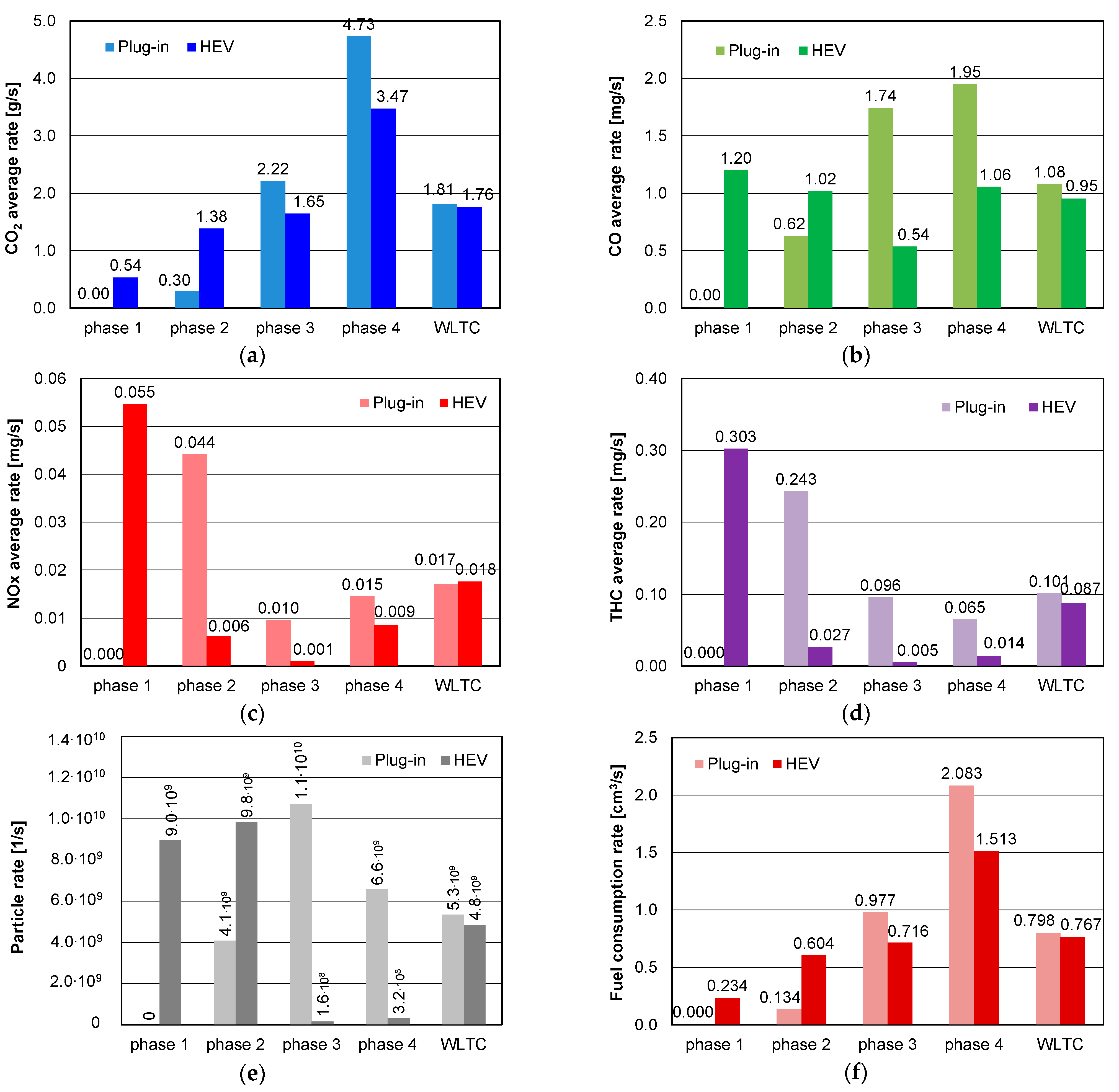
  • Relative to on-road CO2 emissions: phase 4 (57%) and phase 3 (38%) have the largest share;
  • Relative to on-road CO emissions: phase 3 (47%) and phase 4 (37%) have the largest share;
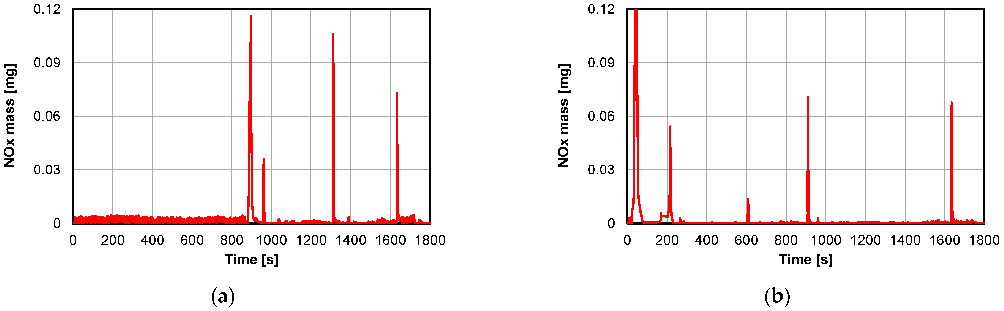
  • Relative to on-road NOx emissions: phase 2 (68%) and phase 4 (17%) account for the largest share;
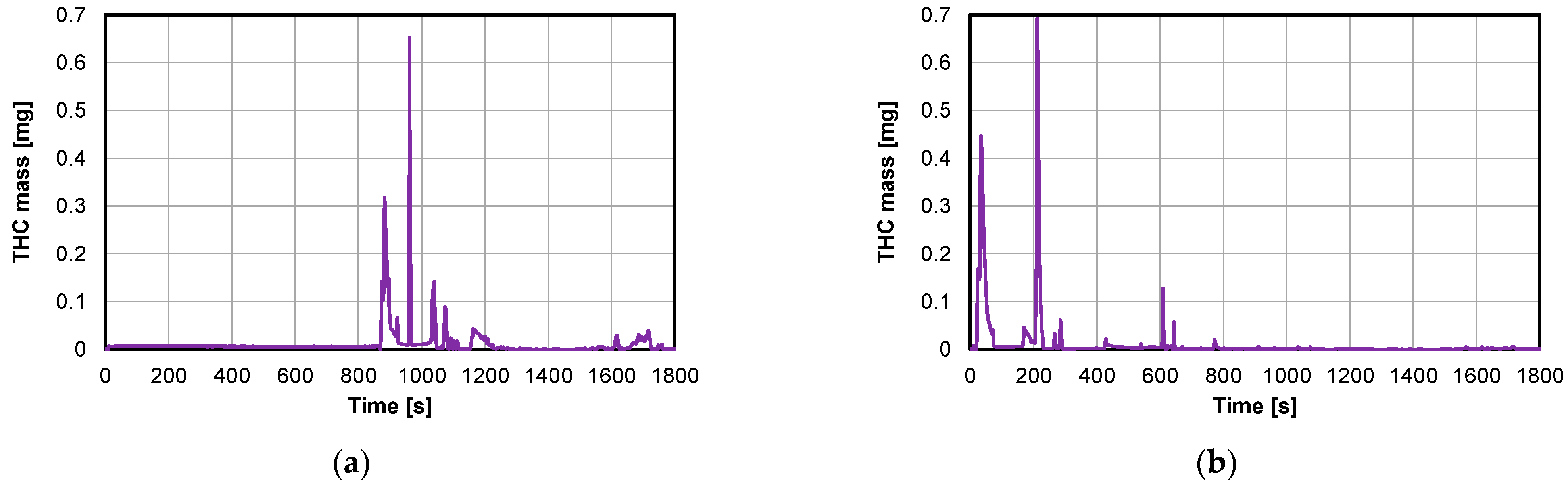
  • Relative to on-road emissions of THC: the largest shares are phase 2 (62%) and phase 3 (26%);
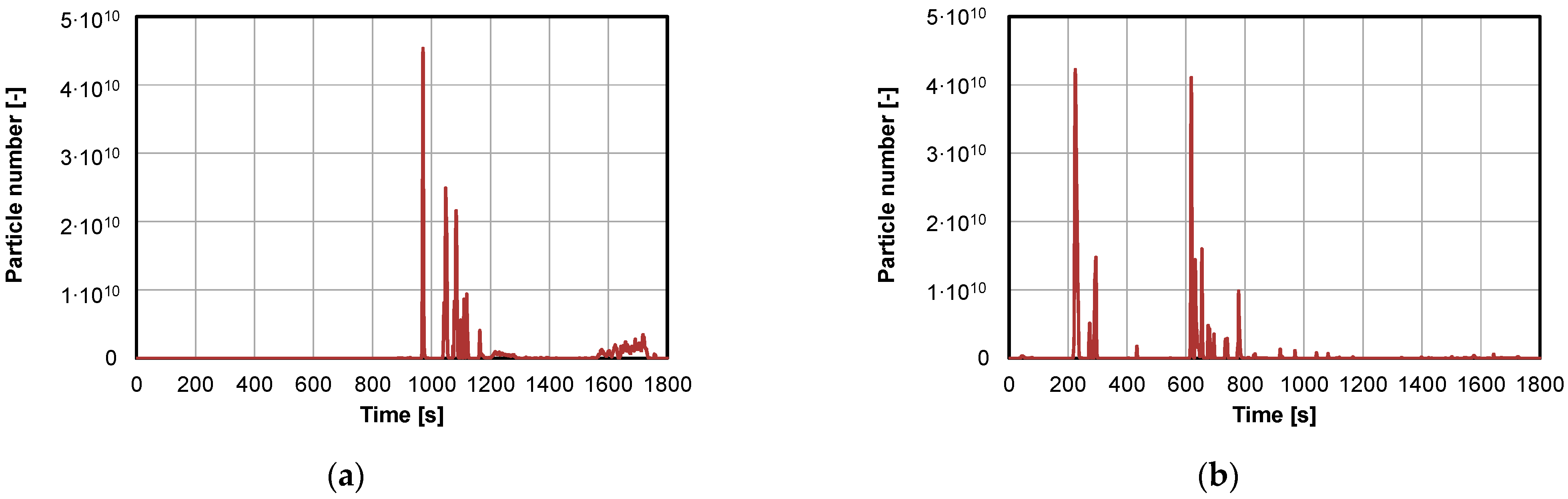
  • Relative to on-road PN emissions: the largest shares are phase 3 (56%) and phase 4 (24%);
  • Relative to mileage fuel consumption: phase 4 (57%) and phase 3 (38%) account for the largest share.
Phase one of the WLTC test, during which the internal combustion engine was not running, is not included in the above summary. However, the total on-road emissions of a component over the entire WLTC test are determined by the mass of the component (at the time of the test, no matter when it was emitted) and the entire distance of the test (even when the vehicle used only electric propulsion).
The analysis of phase shares in total exhaust emissions for the HEV also takes into account the first phase (for which the largest share of the majority of examined exhaust components was observed (Figure 26)). This was due to the fact that the vehicle start-up period is the most crucial in total emissions and to the fact that the lack of significant efficiency of the catalytic reactor causes some components to no be oxidized. The following results were obtained for the HEV-type vehicle:
  • Relative to on-road CO2 emissions: phase 4 of the test has the largest share (40%), and phase 1 has the smallest share (11%); phases 2 and 3 have shares of 22% and 27%, respectively;
  • Relative to on-road CO emissions: the highest share is attributable to phase 1 of the test (41%), and the lowest to phase 3 (14%); phases 2 and 4 account for 25% and 20%, respectively. The main influence on such values in phase 1 is due to engine start-up and catalytic reactor inefficiency. Conversely, the increase in the share in phase 4 is due to the increase in engine load and vehicle speed, i.e., excess of exhaust gases, and possibly too small a volume of the catalytic reactor;
  • Relative to on-road NOx emissions: phase 1 of the test has the largest share (85%) and phase 3 the smallest share (1%); phases 2 and 4 have a share of 7% each; the main influence on such values in phase 1 is engine start-up and lack of efficiency of NOx reduction in the catalytic reactor;
  • Relative to on-road THC emissions: phase 1 of the test has the largest share (91%) and phase 3 the smallest share (1%); phases 2 and 4 have a share of 6% and 2%. The main impact on such values in phase 1 is due to engine start-up and the significant inefficiency of hydrocarbon oxidation in the catalytic reactor; however, the efficiency of hydrocarbon oxidation in phase 4 of the WLTC test was found to be higher than that of carbon monoxide oxidation;
  • Relative to the number of NSAs: phases 1 and 2 of the test account for the largest shares (54% and 44%, respectively); 98% of all particulates are emitted in these two phases;
  • Relative to the mileage fuel consumption: the largest contribution is from phase 4 of the test (40%) and the smallest from phase 1 (11%); phases 2 and 3 contribute 22% and 27%, respectively; this was mainly influenced by the energy demand of the engine (increased driving speed).

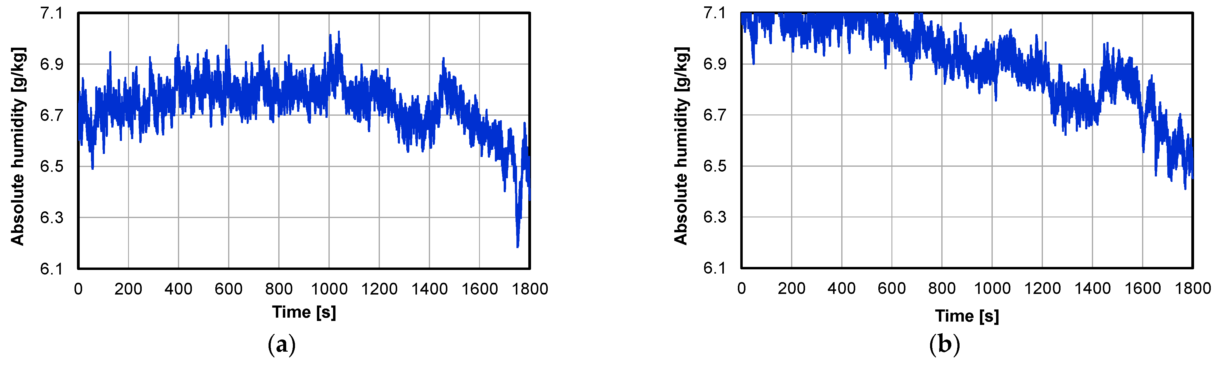
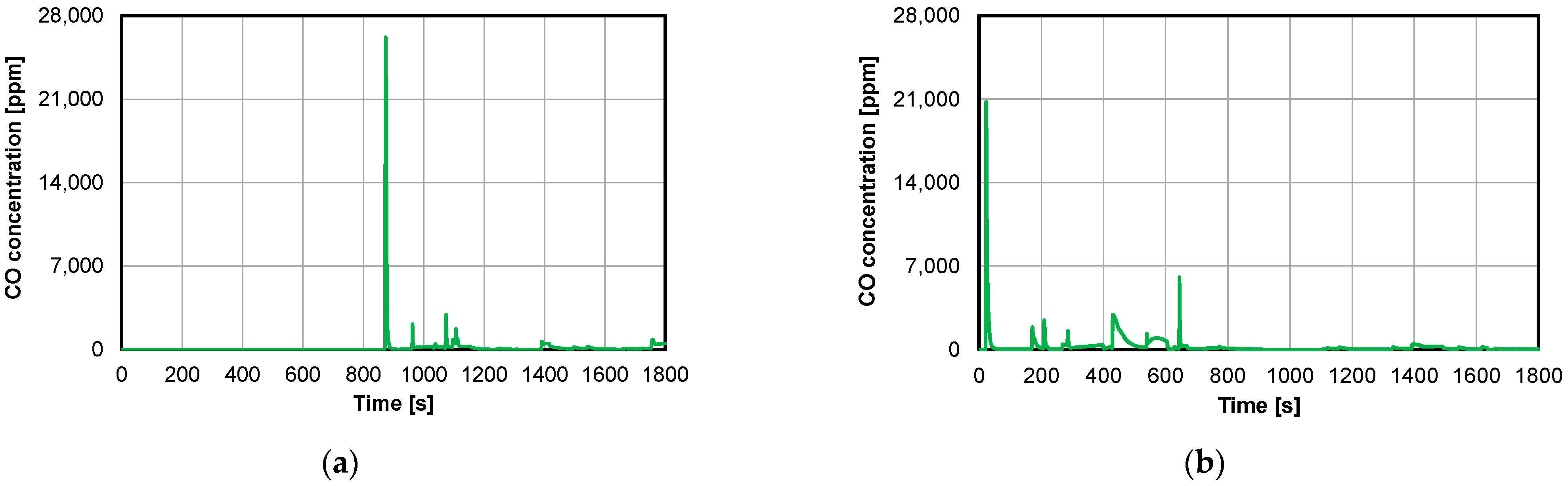
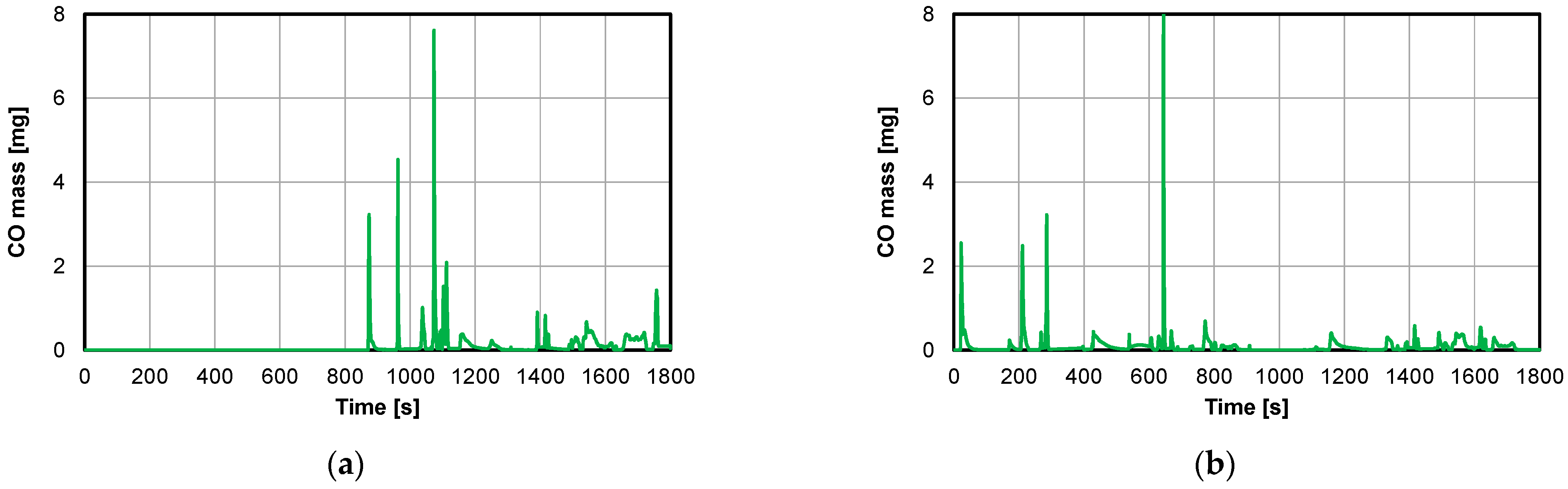
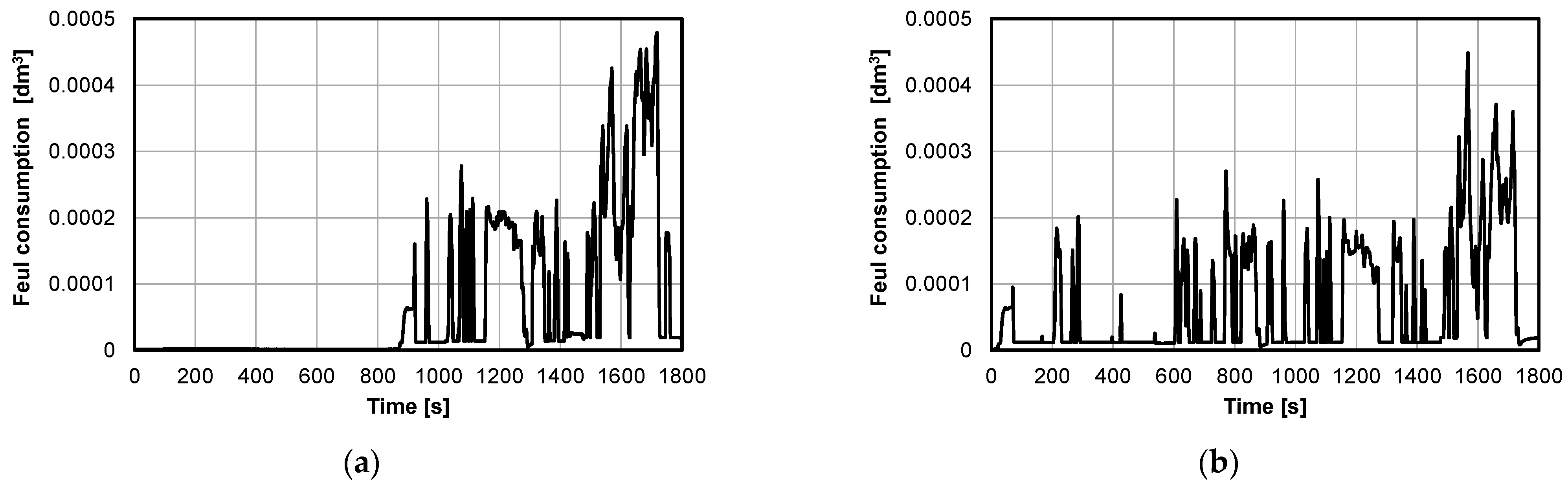
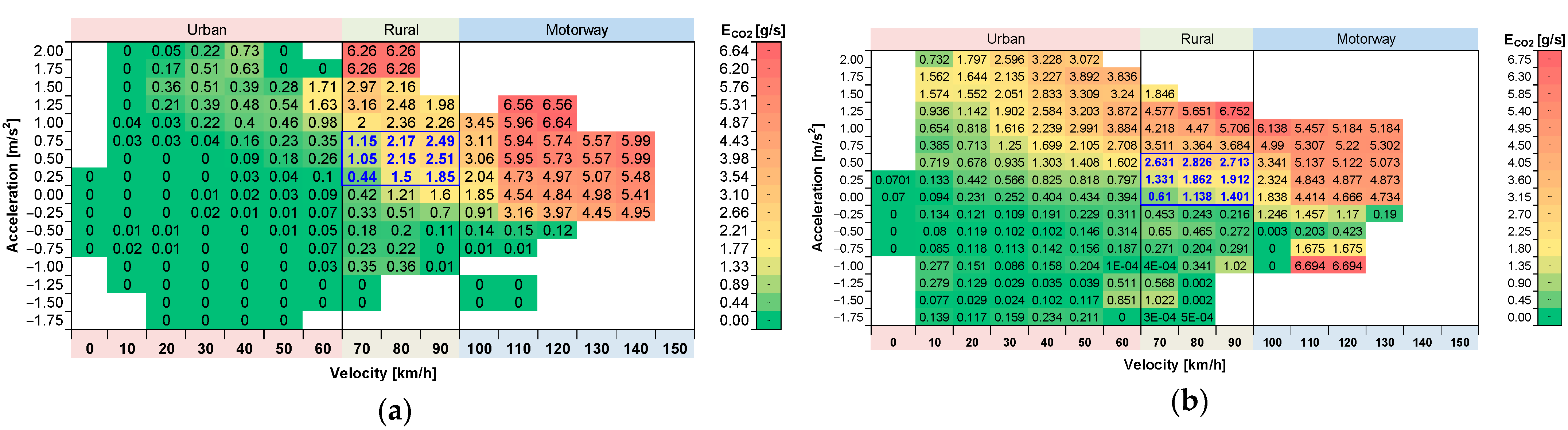
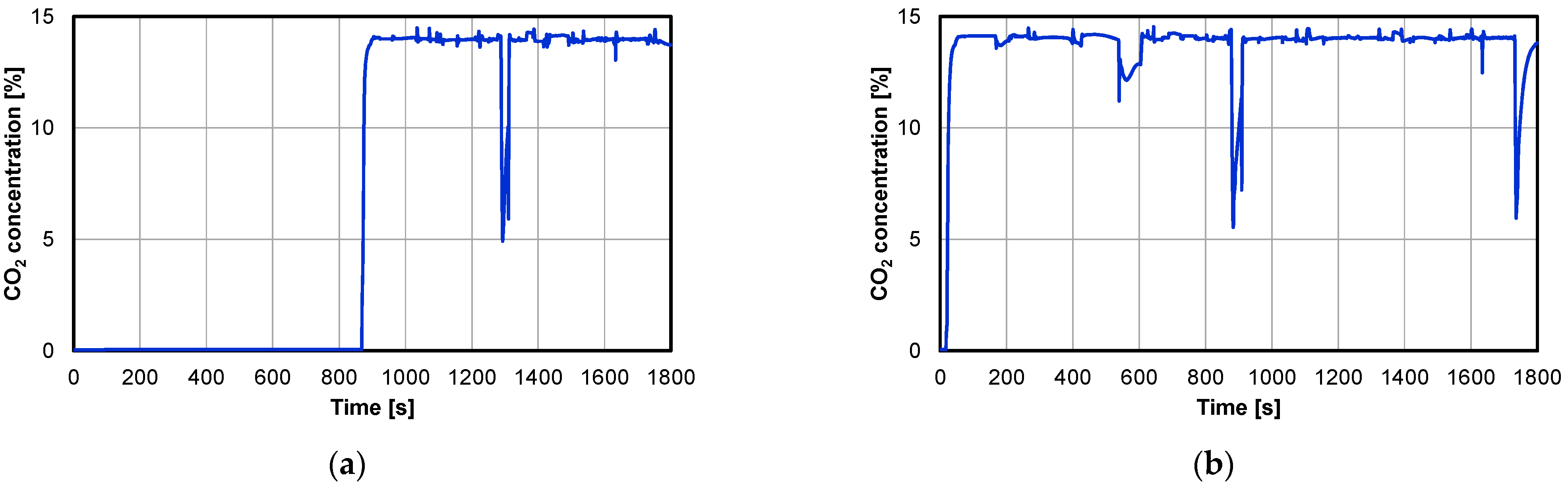
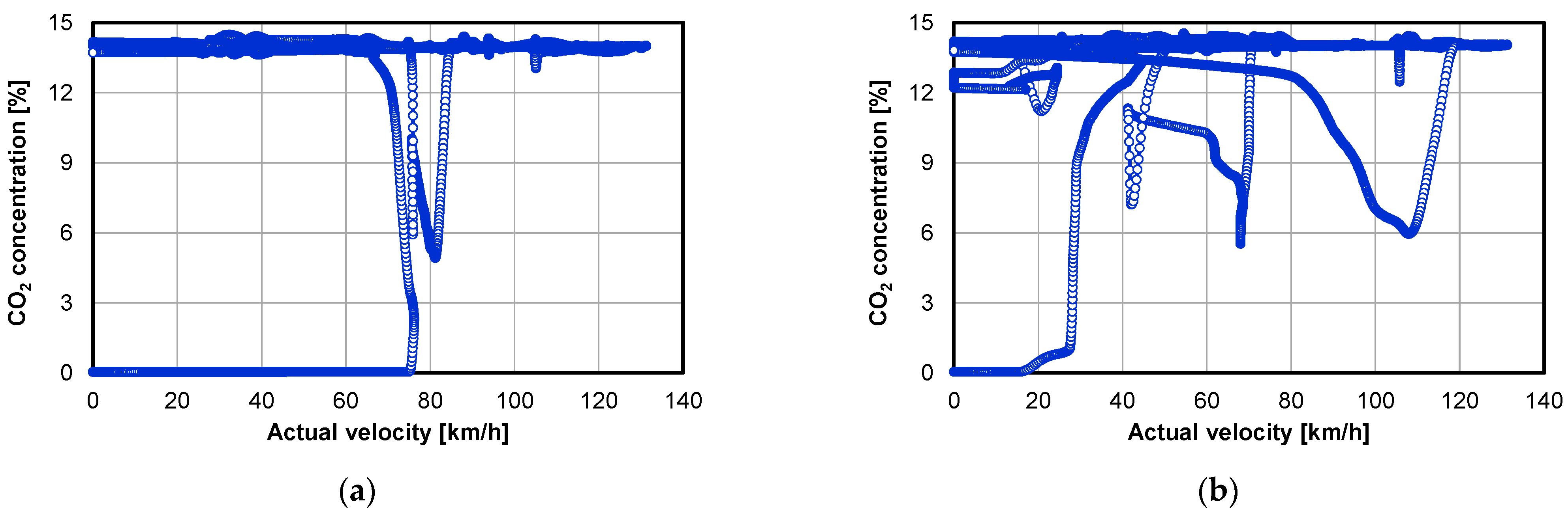
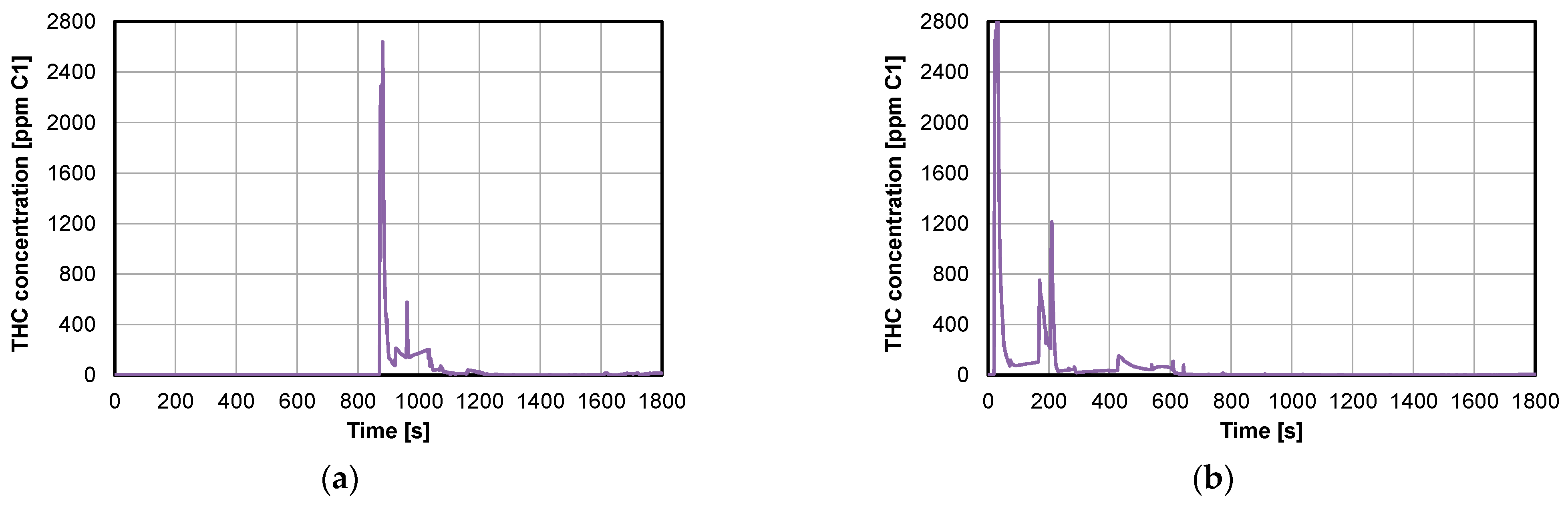
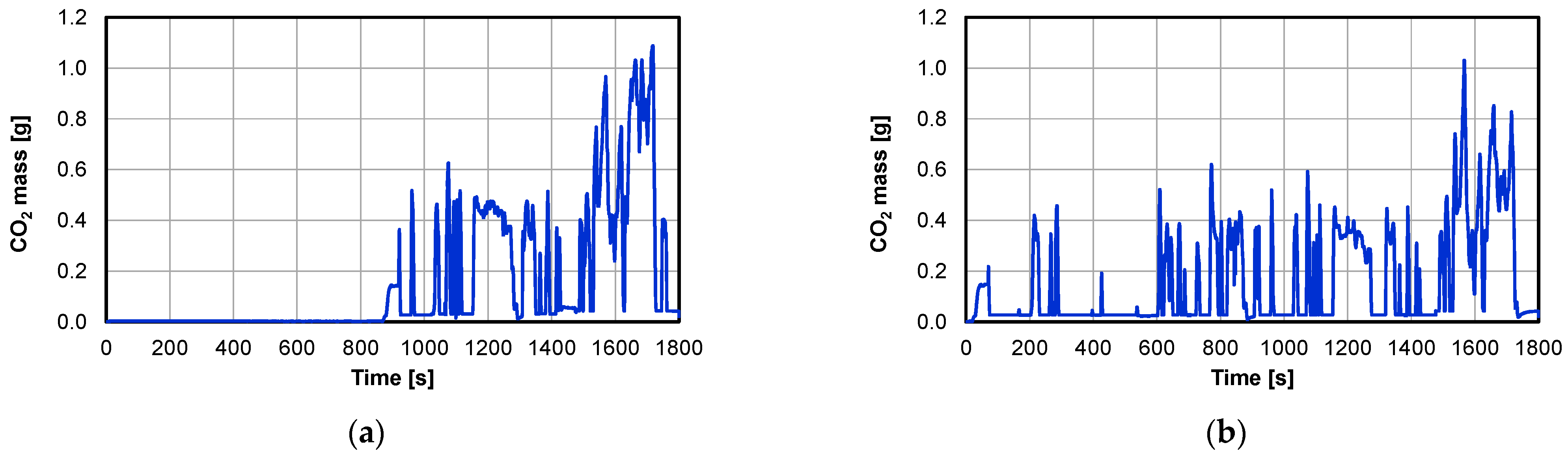
4.2. Real Driving Emission Tests

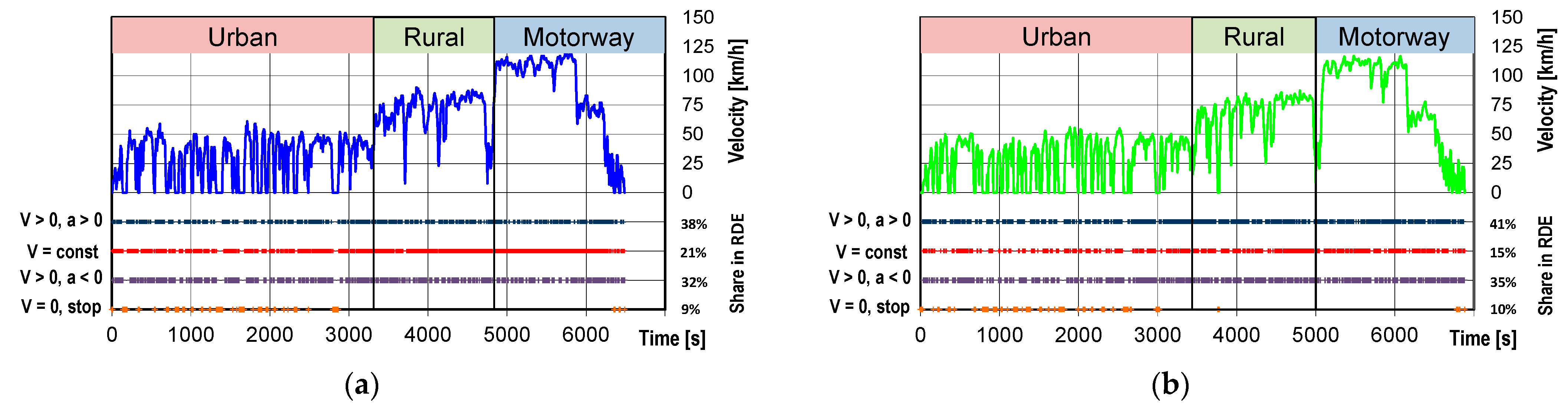
4.2.1. Verification of Test Feasibility Conditions

In order to make a comprehensive comparison of the emissions of the hybrid vehicles, it was necessary to relate the results of the WLTC type-approval test to the emissions results obtained from the tests in real driving conditions. For this reason, RDE tests were also carried out for the same vehicles, the speed courses of which are shown in Figure 27. In addition, the shares of such conditions such as acceleration, constant speed running, braking and stopping are also included. The comparison of these parameters indicates that the runs were similar, which was the basis for further comparison.
The route was divided by maximum speed into three parts: urban, rural and motorway. The division and the percentages (relative to the road) are in accordance with the recommendations of the relevant standards for RDE testing. They represent shares of approximately 33% ± 10% each, which is graphically presented in Figure 28. The urban part is the speed range of 0–50 km/h, the rural part is characterized by speeds in the range of 50 to 90 km/h, and the motorway part is the speed range of over 90 km/h. The final stage of the RDE test is characterized by a short section of rural and urban driving.
The validity of the RDE test is also determined by the dynamic parameters. They determine the dynamics of the vehicle movement in the test, such that the product of the vehicle speed and its acceleration is within the appropriate ranges. There are two indicators used for this purpose:
  • 95th percentile of the product of velocity and acceleration (greater than 0.1 m/s2), determined at each test phase (Figure 29);
  • Relative positive acceleration, also determined at each test phase (Figure 30).
The first indicator must be less than the specified maximum for each speed of the average test phase. Figure 29a,b shows that the test carried out for both the plug-in vehicle and the HEV are within the given limits and are comparable for both vehicles. For the urban part, the values are about 10 m2/s3; for the rural part, the value is about 17 m2/s3; for the motorway part, a slight variation of the values of these indices was recorded for the plug-in vehicle (17 m2/s3) and for the HEV (19 m2/s3). In addition, beyond the requirements, the values of this indicator determined for the WLTC test were compared. It turns out that the 95th percentile of the product of speed and acceleration is only 50% of the value of this indicator in the road test.
The next parameter compared was the relative positive acceleration. In addition, in this case, the determined RPA values for each phase of the RDE test meet the requirements—they are above the line defining their minimum value. For the plug-in vehicle (Figure 30a), the index values in the urban part (RPAU) are 0.18 m/s2; for the rural part, RPAR = 0.08 m/s2; for the motorway part, RPAM = 0.04 m/s2. Similar values to the previous ones were obtained for the HEV: RPAU = 0.16 m/s2, RPAR = 0.10 m/s2, RPAM = 0.04 m/s2 (Figure 30b). The values of RPA in each part of the WLTC test were determined comparatively. The comparison shows that the values of this indicator obtained in the WLTC test are higher than in the RDE test (assuming for comparison individual parts of the WLTC and RDE test: Phase 1—urban, Phase 2, Phase 3—rural, Phase 4—motorway).

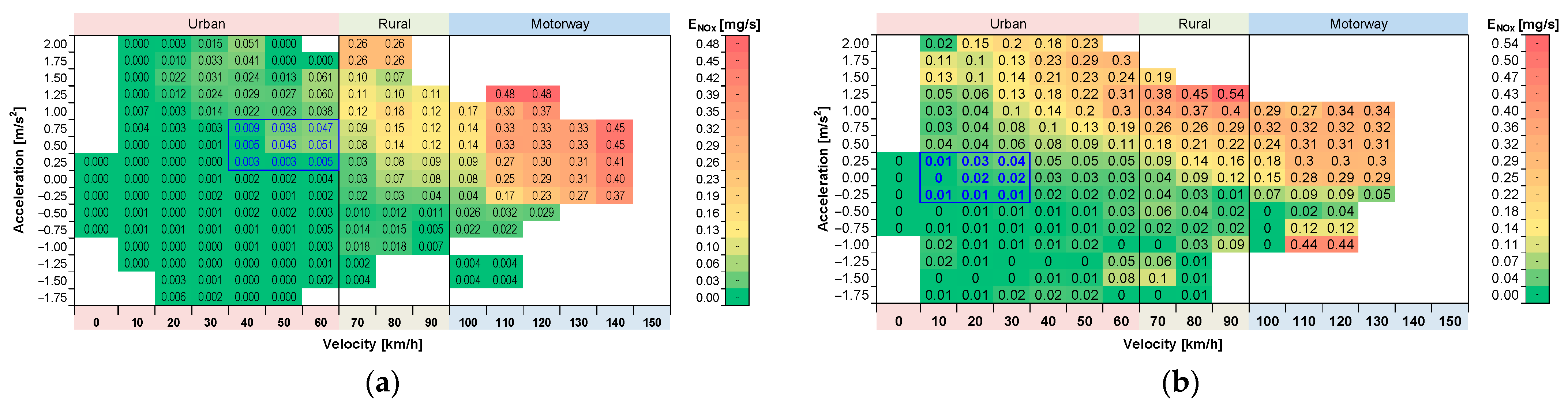
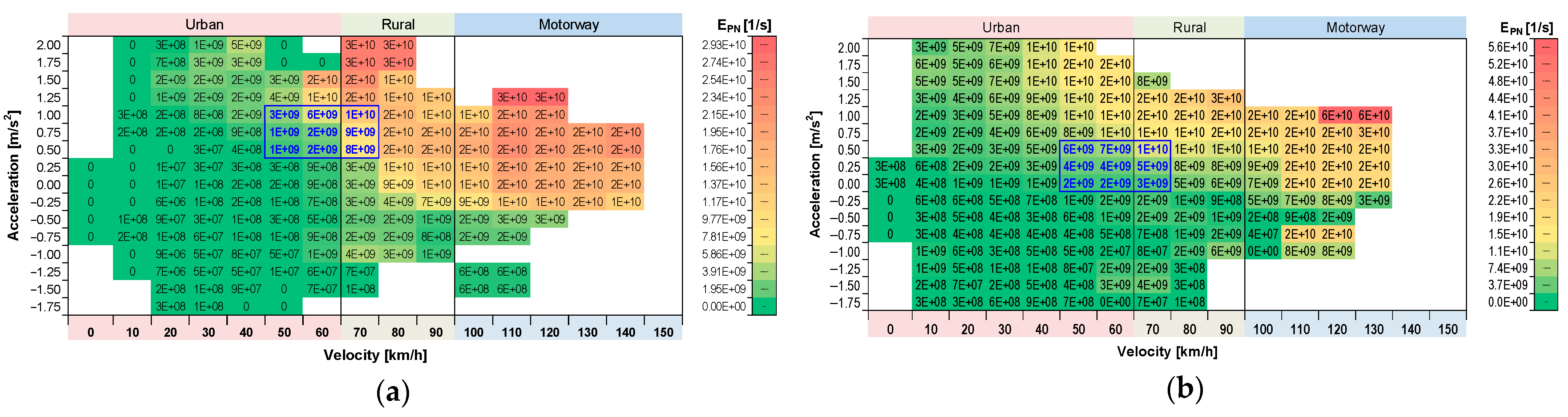
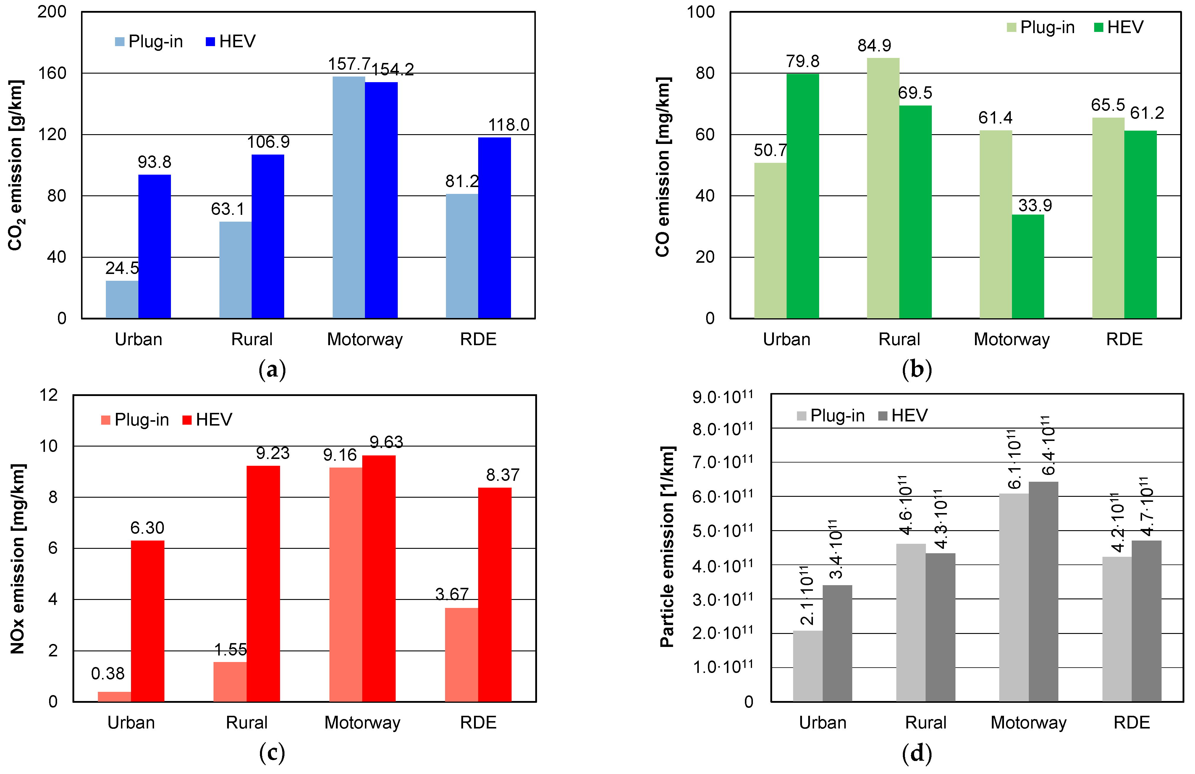
4.2.2. Comparison of Plug-in and HEV Vehicles under Road Test Conditions

Considering the correctness of the test methodology, only after the feasibility of the tests had been checked and their dynamic correctness verified, it was possible to proceed to an ecological comparison of the vehicles. This comparison was made on the basis of emission maps in the vehicle velocity–acceleration coordinates. The choice was dictated by the possibility of evaluating the rate of emission of the considered component of exhaust gases, among others, depending on the dynamic parameters of the vehicle and on the part of the RDE test.
Analysing the rate of CO2 emissions (Figure 31), it is noticeable that the distribution of these values is similar, especially in the rural and motorway parts of the test. Significant differences are observed in the urban part of the test, where the plug-in vehicle’s engine works much less (Figure 30a). For the HEV (Figure 31b), a high rate of CO2 emissions (2–3 g/s) is observed for vehicle speeds in the range of 30–50 km/h and maximum acceleration.
The authors also reported the possibility of estimating a range of vehicle velocity and acceleration such that the CO2 rate of the RDE test is consistent with the WLTC test result. This can be used to approximate the correlation between these indices in different tests. For the exhaust emission under consideration, the range of agreement (mean value of about 1.8 g/s) is found during the rural phase (speed in the 60–90 km/h range) and acceleration in the 0–1 m/s2 range. These ranges are similar for both types of tested vehicles—marked in blue in Figure 31.
A similar analysis was carried out for the CO emission rate. From the data presented, similar conclusions to the previous ones can be drawn for this component. In this example, there is no increased CO emission rate (Figure 32a) for the plug-in vehicle in the urban part for high acceleration values in comparison to the HEV (Figure 32b). This is mainly due to the possibility of support of the combustion engine by the electric motor. Conversely, a much higher rate of CO emissions occurs in the motorway section (at high vehicle acceleration). The estimated ranges of occurrence of a similar rate of CO emission in the RDE test in relation to the WLTC test also overlap. They occur in the rural portion for similar acceleration ranges.
The NOx emission rate characteristics are also different for the plug-in vehicle and the HEV. For the plug-in vehicle, there is a reduced NOx emission rate mainly in the urban and rural part (Figure 33a). However, in the motorway part, it is higher (0.3–0.4 mg/s) than for the HEV vehicle (0.2–0.3 mg/s).
The analysis on particle number rate shows similarity. For the plug-in vehicle (Figure 34a) and HEV (Figure 34b), a similar particle number rate is observed in the highway part, while in the rural part, it is about two-fold smaller for the plug-in. When considering the urban part, the particle number rate is about 5–10 smaller for the plug-in vehicle compared to the HEV. The practical aspect is that the plug-in vehicles can compete to a large extent for low mileage with zero-emission vehicles in city centres (assuming driving starts). However, their utility on rural and motorway routes is similar to HEVs. The estimated values of the ranges of speed and acceleration in which the particle number rate of the WLTC and RDE tests for both vehicles are similar occur for the speed of 50–70 km/h and acceleration from 0.5 to 1.0 m/s2 (plug-in), while for HEV, it is in the acceleration range of 0–0.5 m/s2.
By using the MAW (Mowing Average Window) algorithm and knowing the instantaneous on-road emissions of CO2, CO, NOx, and PN, the on-road emissions of each exhaust emission compound can be determined. The final result can be obtained for each test phase (urban, rural, motorway) and for the entire RDE test. Using this procedure, the on-road emissions of the various compounds were determined for the plug-in vehicle and the HEV.
Comparing the on-road emissions of carbon dioxide (Figure 35a), the plug-in vehicle emits almost 70% less carbon dioxide in the urban phase and 40% less in the rural phase. This is the result of combining the energy from the combustion engine and the electric motor. In the motorway phase, the differences are negligible, as both vehicles use an internal combustion engine. The total on-road CO2 emissions in the RDE test are a weighted average of the three phases; thus, the final emissions are about 30% less for the plug-in vehicle compared to the HEV.
The situation is slightly different for carbon monoxide emissions. Due to the first cold start of the plug-in vehicle engine in the rural phase, the emissions in this part are much higher (by 20%) than for the HEV (Figure 35b). This situation also affects the next phase—the motorway phase. The HEV running in the early urban phase has time to reach a sufficient temperature of the aftertreatment systems; thus, the oxidation of CO to CO2 occurs with greater efficiency. This is also reflected in the total on-road emissions, which are 6% higher for the plug-in vehicle compared to the HEV. However, the on-road carbon monoxide emission values (60–65 mg/km) are well below the Euro 6d-Temp emission limit of 1000 mg/km.
The comparison of on-road emissions of nitrogen oxides shows significant advantages for the plug-in vehicle (Figure 35c). These emissions in the urban phase are minimal for the plug-in vehicle (0.38 mg/km) and are only a few percent of the emission value for the HEV (6.30 mg/km). The situation is similar for the rural phase—starting the plug-in vehicle’s internal combustion engine in this phase does not result in too high of on-road emissions (1.55 mg/km), as the result is offset by electric mode operation. For the HEV, the on-road emission of nitrogen oxides is 9.23 mg/km, which is about six times higher than the plug-in vehicle. The highway phase is characterized by similar emission values, resulting in a final value for the plug-in vehicle of about 50% lower than for the HEV. Such values are within the permissible limit of the RDE test (1.43 × 60 mg/km = 86 mg/km).
Comparing the particle number for plug-in and HEV vehicles (Figure 35d), there is a high similarity between the values in the different phases of the study. The values are not close in the urban phase (a difference of about 50% in favour of the plug-in vehicle), while the other phases show differences of about 10%. This situation has consequences in the emissions of the entire RDE test, where the plug-in vehicle recorded only a 10% lower value than the HEV vehicle. This is mainly due to the lack of a particulate filter in these vehicles, which does not prevent them from meeting the permissible limits in the RDE test (increasing the limit by a value of 1.5, which translates into a permissible level of 1.5 × 6∙1011 1/km = 9∙1011 1/km).

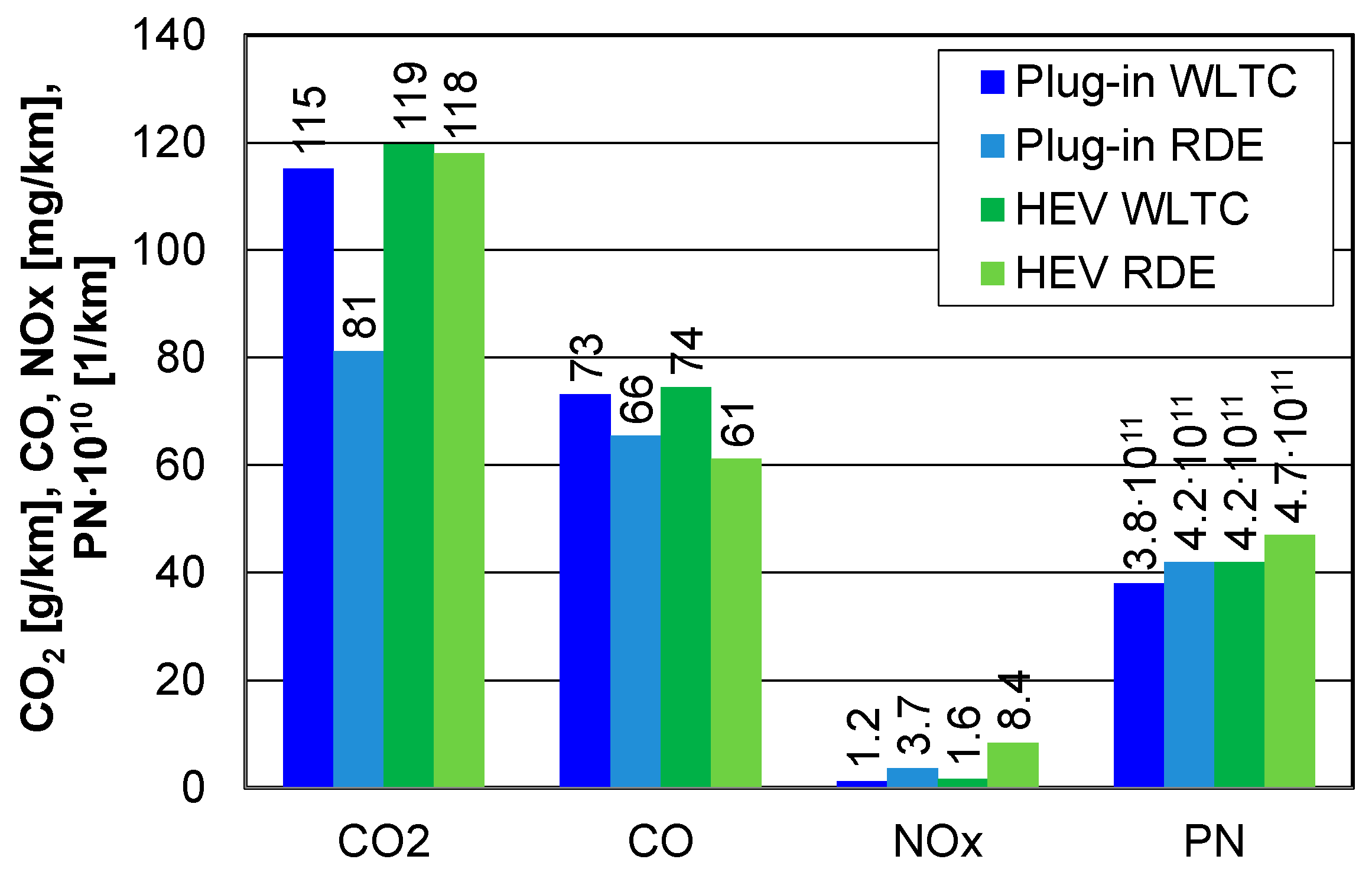
4.2.3. Comparison of Emission Results in the WLTC and RDE Test

The comparison of road emission factors was made under the assumption of determining the relative distance of the test under consideration. To standardise different lengths of the distance in the test, a comparative index was defined, which can be described as the total road emission from the beginning of the test (bi,j) in relation to the final road emission (bj). The index will make the qualitative changes visible, which will be the basis for making a statement about the environmental performance of the drive during the research test. Unfortunately, the disadvantage of such a solution is its “memory”, as it understates the value of the road emission for the plug-in vehicle. This is the result of the initial period of operation of such a vehicle, which is electric mode.
For the plug-in vehicle, the start of the internal combustion engine can be observed, regardless of the test. In the WLTC test, this is the moment for which the relative distance value is 0.27 (Figure 36a). The nature of the changes in the relative emissions of CO, NOx, and PN is abrupt in the first stage but does not exceed a value of 2. This means that the road emission of a component is not two times the final value obtained in the entire WLTC test. After the sharp increase, a decrease in relative emissions is observed, but such a trend does not occur for the road emission of carbon dioxide. In this case, the nature of the changes is incremental, which is due to the proportional consumption of fuel as a function of vehicle velocity. For the same vehicle in the RDE test (Figure 36c), the relative emission rate changes in a similar manner, but does not exceed a value equal to one. This is a result of the later (relative to the road) start of the internal combustion engine (di/d = 0.4). However, the nature of the changes in relative CO emissions is similar to the previous one—the increase is sharp, suggesting high carbon monoxide emissions directly after engine start-up in both cases. The relative emissions of the other components change in a similar but less rapid manner.
The relative on-road emissions for the HEV have a completely different characteristic, which is due to the almost immediate start of the internal combustion engine after the start of the test. During the initial period of the WLTC test (Figure 36b), a significant increase in the rates of all exhaust components is apparent, which is due to the fact that the increase in mass of the harmful compounds is much greater than the increase in distance. The effect is also exacerbated by cold starting and engine load. Increasing the load on the engine also has a positive effect—it shortens the warm-up period of the engine and at the same time accelerates the moment in which the exhaust aftertreatment systems reach their highest efficiency. The first period of the WLTC test (up to a value of di/d < 0.3) is characterized by a value of bi/b > 2, which is where the HEV emits the most—the plug-in vehicle moves with the use of an electric motor. Similar characteristics of change were also present for the HEV during the RDE test (Figure 36d). Initially, significantly high relative CO emissions were observed, which is typical for all test cases. The relative on-road NOx emissions had a different pattern—they gradually increased, which was due to the low concentration of this compound from the beginning of the engine start (the influence of cold start). In the next period, NOx emissions increased because of higher engine load, which was not effectively compensated by the catalytic reactor. The highest relative emission of compounds occurred during the first 10% of the RDE test distance (about 10 km).
In order to comprehensively develop and comment on the changes in emissions for the plug-in and HEV vehicles, the above study needs to be supplemented with a comment on electrical performance. The plug-in vehicle uses a battery with an energy capacity of 8.8 kWh, while the HEV uses a battery with an energy capacity of 3.3 kWh. Such significant differences in battery energy capacity must reflect the ecological characteristics of the vehicles.
Plug-in vehicle tests were performed with the battery at maximum charge (SOC = 80–85%), and during the test, the battery was discharged to a value of 15% (RDE) or 16% (WLTC). For the WLTC test (Figure 37a), battery discharge occurred at a relative distance value of di/d = 0.3 (about 7 km), and in the RDE test (Figure 36b), at a value of di/d = 0.4 (about 40 km). The differences in absolute distance values are due to the possibility of energy recovery—in the RDE test, such states (braking) were much higher than in the WLTC test. When the battery was discharged, it was followed by micro-discharges due to the operation of the internal combustion engine or the energy recovery capability.
The HEV was equipped with a system that did not allow for initial SOC formation. The initial SOC values regardless of the test were in the 40–50% range. During the WLTC test, the values varied from 30% to a value of 70% and were highly dependent on the energy management strategy of the vehicle (Figure 37a). For the RDE test, changes in SOC in the urban and rural part and a flat course (minimum SOC values) in the motorway part are characteristic. However, reducing the vehicle speed in the final phase of the RDE test allowed the battery to recharge quickly to SOC values > 60%.

5. Conclusions

The results obtained for the emissions related to the load of the road and the operability of the dynamometer are enriching for research and development departments of the industry. All the parameters analysed, including the real values of speed, emissions, the competitive options between the combustion engine and the electric motor, the acceleration and deceleration events existing during the test, and the other factors, are references for this type of advancement in the world of vehicle development with minimum power engagement.
Tests conducted on exhaust emissions from plug-in and HEV vehicles confirmed the long observed assumption of similar exhaust emissions from such vehicles. However, careful analysis reveals detailed correlations that—reported only as final results in the WLTC test—differ slightly. The results of the analysis indicate that the on-road CO2 emissions for the plug-in vehicle are about 3% lower compared to the HEV (Figure 38). The remaining results of pollutant emissions obtained for the tested vehicles show that lower emissions of pollutants prevailed for the plug-in vehicle (CO2—3%, CO—2%, NOx—25%, THC—13%, PN—10%, FC—3%), despite the fact that it was a vehicle with a higher curb weight. This is mainly due to the operation of the electric motor in the first stage of the test; the inclusion of the internal combustion engine to drive the vehicle in the second stage of the WLTC test results in faster thermal stabilization of the engine and the catalytic reactor, which significantly reduces emissions of all other exhaust components. However, the weight of the plug-in vehicle was about 170 kg, which translated into a higher electrical capacity of the battery pack by about 7.5 kWh.
Significantly greater differences are observed in actual traffic conditions, where the plug-in vehicle emits about 30% less carbon dioxide. In addition, for this type of vehicle, there are lower nitrogen oxide emissions (by 50%) compared to the HEV, as well as particulate matter numbers (about 10% lower). There were higher carbon monoxide emissions in the RDE test by about 6% for the plug-in vehicle compared to the HEV. The test results obtained clearly indicate that the potential for reducing emissions and fuel consumption is much higher for plug-in vehicles when used for short routes with a significant proportion of electric engine use.
The exhaust emissions and energy intensity results presented in this paper relate to the two specific vehicles tested. However, points should be noted regarding:
  • Performing WLTC tests with the assumption that the tests on a chassis dynamometer take place under repeatable conditions—the test results are transferable to other (similar) hybrid vehicles;
  • In RDE, the conditions do not allow for free variation of the test conditions—the feasibility conditions must be fulfilled and the criteria defined by their acceptable ranges. The state of charge in plug-in vehicles is arbitrary. The initial state of charge will determine the test results, and the knowledge of the initial state of charge is often decisive for the economic operation of such vehicles—this issue has also been raised in other studies [92,93,94].

Author Contributions

Conceptualization, J.P., K.S. (Kinga Skobiej), and K.S. (Krzysztof Siczek); methodology, J.P., K.S. (Kinga Skobiej), K.S. (Krzysztof Siczek), and P.K.; software, K.S. (Kinga Skobiej) and J.P.; validation, K.S. (Krzysztof Siczek), K.S. (Kinga Skobiej), and J.P.; formal analysis, J.P., K.S. (Kinga Skobiej), and P.K.; investigation, K.S. (Krzysztof Siczek) and M.W.; resources, M.W.; data curation, J.P.; writing—original draft preparation, K.S. (Krzysztof Siczek) and J.P.; writing—review and editing, K.S. (Kinga Skobiej) and K.S. (Krzysztof Siczek); visualization, J.P., K.S. (Kinga Skobiej), and K.S. (Krzysztof Siczek). All authors have read and agreed to the published version of the manuscript.

Funding

This research received no external funding.

Institutional Review Board Statement

Not applicable.

Informed Consent Statement

Not applicable.

Data Availability Statement

MDPI Research Data Policies.

Conflicts of Interest

The authors declare no conflict of interest.

Abbreviations

aAcceleration Vehicle
bRoad Exhaust Emission
BEVBattery Electric Vehicle
CFConformity Factor
EExhaust Emission Rate
EMElectric Motor
EVElectric Vehicle
FCFuel Consumption
GNGGeneralized Reduced Gradient
hDriving Test Altitude
HEVHybrid Electric Vehicle
ICEInternal Combustion Engines
MMotorway
NEDCNew European Driving Cycle
PEMSPortable Emission Measurement System
PHEVPlug-in Hybrid Electric Vehicle
PNParticle number
RRural
RDEReal Driving Emissions
RPARelative Positive Acceleration
SDistance
tTime
uShare
UUrban
vVehicle Velocity
WLTCWorldwide-harmonized Light duty Vehicles Test Cycle
WLTPWorldwide-harmonized Light duty Vehicles Test Procedure

References

  1. Hybrids Are 14 Times Better than Battery Electric Vehicles at Reducing Real-World Carbon Dioxide Emissions. Emissions Analytics Newsletter. 14 June 2019. Available online: https://www.emissionsanalytics.com/news/hybrids-are-better (accessed on 9 November 2021).
  2. Jung, H.; Li, C. Emissions from Plug-In Hybrid Electric Vehicle (PHEV) during Real World Driving Under Various Weather Conditions; UC Davis: National Center for Sustainable Transportation: Davis, CA, USA, 2018; Available online: https://escholarship.org/uc/item/0c4842fp (accessed on 15 November 2021).
  3. Wu, X.; Zhang, S.; Wu, Y.; Li, Z.; Ke, W.; Fu, L.; Hao, J. On-road Measurement of Gaseous Emissions and Fuel Consumption for Two Hybrid Electric Vehicles in Macao. Atmos. Pollut. Res. 2015, 6, 858–866. [Google Scholar] [CrossRef]
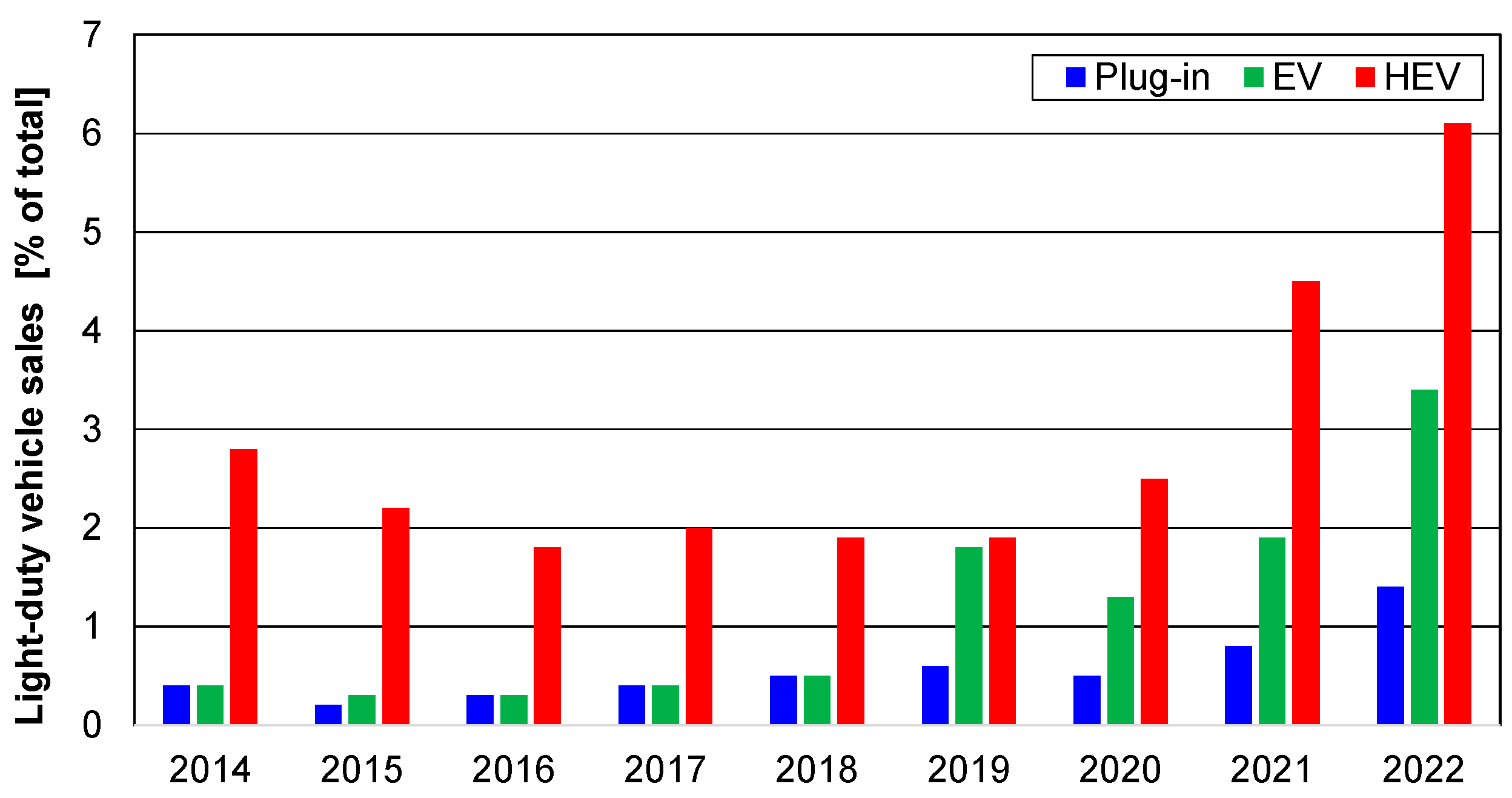
  4. Electric Vehicles and Hybrids Surpass 10% of U.S. Light-Duty Vehicle Sales. Today in Energy, U.S. Energy Information Administration. Available online: https://www.eia.gov/todayinenergy/detail.php?id=51218# (accessed on 8 March 2022).
  5. Pielecha, J.; Skobiej, K.; Kurtyka, K. Exhaust Emissions and Energy Consumption Analysis of Conventional, Hybrid, and Electric Vehicles in Real Driving Cycles. Energies 2020, 13, 6423. [Google Scholar] [CrossRef]
  6. Bielaczyc, P.; Merkisz, J.; Pielecha, J.; Woodburn, J. A Comparison of Gaseous Emissions from a Hybrid Vehicle and a Non-Hybrid Vehicle under Real Driving Conditions; Technical Paper 2018-01-1272; SAE International: Warrendale, PA, USA, 2018. [Google Scholar] [CrossRef]
  7. Greenwood, S. Hybrid Vehicles—A Simple Guide. Aathornton. September 2017. Available online: https://www.aathornton.com/hybrid-vehicles-simple-guide/ (accessed on 9 November 2021).
  8. Galassi, M.C.; Stutenberg, K.; Garcia Otura, M.; Trentadue, G.; Scholz, H.W.; Carriero, M. Electric and Hybrid Vehicle Testing: BMWi3 Performance Assessment in Realistic Use Scenarios; EUR 29035 EN, JRC109797; Publications Office of the European Union: Luxembourg, 2018. [Google Scholar] [CrossRef]
  9. Cieslik, W.; Szwajca, F.; Zawartowski, J.; Pietrzak, K.; Rosolski, S.; Szkarlat, K.; Rutkowski, M. Capabilities of Nearly Zero Energy Building (nZEB) Electricity Generation to Charge Electric Vehicle (EV) Operating in Real Driving Conditions (RDC). Energies 2021, 14, 7591. [Google Scholar] [CrossRef]
  10. Machado, P.G.; Teixeira, A.C.R.; de Almeida Collaço, F.M.; Hawkes, A.; Mouette, D. Assessment of Greenhouse Gases and Pollutant Emissions in the Road Freight Transport Sector: A Case Study for São Paulo State, Brazil. Energies 2020, 13, 5433. [Google Scholar] [CrossRef]
  11. Temporelli, A.; Carvalho, M.L.; Girardi, P. Life Cycle Assessment of Electric Vehicle Batteries: An Overview of Recent Literature. Energies 2020, 13, 2864. [Google Scholar] [CrossRef]
  12. Höltl, A.; Macharis, C.; de Brucker, K. Pathways to Decarbonise the European Car Fleet: A Scenario Analysis Using the Backcasting Approach. Energies 2018, 11, 20. [Google Scholar] [CrossRef] [Green Version]
  13. Palencia, J.C.G.; Nguyen, V.T.; Araki, M.; Shiga, S. The Role of Powertrain Electrification in Achieving Deep Decarbonization in Road Freight Transport. Energies 2020, 13, 2459. [Google Scholar] [CrossRef]
  14. Fulton, L. A Publicly Available Simulation of Battery Electric, Hybrid Electric, and Gas-Powered Vehicles. Energies 2020, 13, 2569. [Google Scholar] [CrossRef]
  15. Zhuang, W.; Zhang, X.; Peng, H.; Wang, L. Simultaneous Optimization of Topology and Component Sizes for Double Planetary Gear Hybrid Powertrains. Energies 2016, 9, 411. [Google Scholar] [CrossRef]
  16. Pielecha, I.; Cieslik, W.; Szalek, A. Impact of Combustion Engine Operating Conditions on Energy Flow in Hybrid Drives in RDC Tests; Technical Paper 2020-01-2251; SAE International: Warrendale, PA, USA, 2020. [Google Scholar] [CrossRef]
  17. Folkson, R. Alternative Fuels and Advanced Vehicle Technologies for Improved Environmental Performance: Towards Zero Carbon Transportation; Woodhead Publishing Limited: Cambridge, UK, 2014. [Google Scholar] [CrossRef]
  18. Shen, C.; Shan, P.; Gao, T. A Comprehensive Overview of Hybrid Electric Vehicles. Int. J. Veh. Technol. 2011, 2011, 571683. [Google Scholar] [CrossRef]
  19. Li, P.; Yan, J.; Tu, Q.; Pan, M.; Xue, J. A Novel Energy Management Strategy for Series Hybrid Electric Rescue Vehicle. Math. Probl. Eng. 2018, 2018, 8450213. [Google Scholar] [CrossRef] [Green Version]
  20. Liu, C.; Liu, Y. Energy Management Strategy for Plug-In Hybrid Electric Vehicles Based on Driving Condition Recognition: A Review. Electronics 2022, 11, 342. [Google Scholar] [CrossRef]
  21. Vu, T.M.; Moezzi, R.; Cyrus, J.; Hlava, J.; Petru, M. Parallel Hybrid Electric Vehicle Modelling and Model Predictive Control. Appl. Sci. 2021, 11, 10668. [Google Scholar] [CrossRef]
  22. Chen, P.-T.; Yang, C.-J.; Huang, K.D. Dynamic Simulation and Control of a New Parallel Hybrid Power System. Appl. Sci. 2020, 10, 5467. [Google Scholar] [CrossRef]
  23. Fu, Z.; Wang, B.; Song, X.; Liu, L.; Wang, X. Power-Split Hybrid Electric Vehicle Energy Management Based on Improved Logic Threshold Approach. Math. Probl. Eng. 2013, 2013, 840648. [Google Scholar] [CrossRef]
  24. Nazari, S.; Siegel, J.; Middleton, R.; Stefanopoulou, A. Power Split Supercharging: A Mild Hybrid Approach to Boost Fuel Economy. Energies 2020, 13, 6580. [Google Scholar] [CrossRef]
  25. Bonfiglio, A.; Lanzarotto, D.; Marchesoni, M.; Passalacqua, M.; Procopio, R.; Repetto, M. Electrical-Loss Analysis of Power-Split Hybrid Electric Vehicles. Energies 2017, 10, 2142. [Google Scholar] [CrossRef] [Green Version]
  26. Son, H.; Park, K.; Hwang, S.; Kim, H. Design Methodology of a Power Split Type Plug-In Hybrid Electric Vehicle Considering Drivetrain Losses. Energies 2017, 10, 437. [Google Scholar] [CrossRef] [Green Version]
  27. Chen, Z.; Hu, H.; Wu, Y.; Xiao, R.; Shen, J.; Liu, Y. Energy Management for a Power-Split Plug-In Hybrid Electric Vehicle Based on Reinforcement Learning. Appl. Sci. 2018, 8, 2494. [Google Scholar] [CrossRef] [Green Version]
  28. Dinh, T.Q.; Marco, J.; Niu, H.; Greenwood, D.; Harper, L.; Corrochano, D. A Novel Method for Idle-Stop-Start Control of Micro Hybrid Construction Equipment—Part A: Fundamental Concepts and Design. Energies 2017, 10, 962. [Google Scholar] [CrossRef] [Green Version]
  29. Capata, R.; Sciubba, E. Study, Development and Prototyping of a Novel Mild Hybrid Power Train for a City Car: Design of the Turbocharger. Appl. Sci. 2021, 11, 234. [Google Scholar] [CrossRef]
  30. Benevieri, A.; Carbone, L.; Cosso, S.; Kumar, K.; Marchesoni, M.; Passalacqua, M.; Vaccaro, L. Series Architecture on Hybrid Electric Vehicles: A Review. Energies 2021, 14, 7672. [Google Scholar] [CrossRef]
  31. León, R.; Montaleza, C.; Maldonado, J.L.; Tostado-Véliz, M.; Jurado, F. Hybrid Electric Vehicles: A Review of Existing Configurations and Thermodynamic Cycles. Thermo 2021, 1, 134–150. [Google Scholar] [CrossRef]
  32. Koreny, M.; Simonik, P.; Klein, T.; Mrovec, T.; Ligori, J.J. Hybrid Research Platform for Fundamental and Empirical Modeling and Analysis of Energy Management of Shared Electric Vehicles. Energies 2022, 15, 1300. [Google Scholar] [CrossRef]
  33. Mierlo, J.V. Special Issue “Plug-In Hybrid Electric Vehicle (PHEV)”. Appl. Sci. 2019, 9, 2829. [Google Scholar] [CrossRef] [Green Version]
  34. Lee, S.; Choi, J.; Jeong, K.; Kim, H. A Study of Fuel Economy Improvement in a Plug-in Hybrid Electric Vehicle using Engine on/off and Battery Charging Power Control Based on Driver Characteristics. Energies 2015, 8, 10106–10126. [Google Scholar] [CrossRef] [Green Version]
  35. Yang, Y.; Ali, K.; Roeleveld, J.; Emadi, A. State-of-the-art Electrified Powertrains-Hybrid, Plug-in, and Electric Vehicles. Int. J. Powertrains 2016, 5, 1. [Google Scholar] [CrossRef]
  36. What Is a Hybrid Car and How Do They Work? Car and Driver. 2019. Available online: https://www.caranddriver.com/features/a26390899/what-is-hybrid-car/ (accessed on 9 November 2021).
  37. Oleksowicz, S.; Burnham, K. Assessment of Hybrid Vehicle Braking Technologies. Mech. Tech. Trans. 2012, 109, 157–168. [Google Scholar]
  38. Duoba, M.; Anderson, J.; Ng, H. Issues in Emissions Testing of Hybrid Electric Vehicles; Argonne National Laboratory: Du Page County, IL, USA, 2000; Available online: https://digital.library.unt.edu/ark:/67531/metadc705904/ (accessed on 28 October 2021).
  39. WLTP Facts. Available online: https://www.wltpfacts.eu/what-is-wltp-how-will-it-work/ (accessed on 9 November 2021).
  40. Fly, A. Are Plug-in Hybrid Cars Worse for Environment than Factory Tests Suggest? It depends how you drive them. The Conversation. 21 September 2020. Available online: https://theconversation.com/are-Plug-in-hybrid-cars-worse-for-environment-than-factory-tests-suggest-it-depends-how-you-drive-them-146598 (accessed on 19 November 2021).
  41. Marignetti, F.; D’Aguanno, D.; Volpe, G. Design and Experiments of a Test Equipment for Hybrid and Electric Vehicle Drivetrains. In Proceedings of the 2017 Twelfth International Conference on Ecological Vehicles and Renewable Energies (EVER), Monte Carlo, Monaco, 11–13 April 2017; pp. 1–6. [Google Scholar] [CrossRef]
  42. Figenbaum, E.; Weber, C. Experimental Testing of Plug-In Hybrid Vehicles. CO2-Emission, Energy Consumption and Local Pollution; TØI Report 1539/2016; Norwegian Centre for Transport Research, Institute of Transport Economics: Oslo, Norway, 2016. [Google Scholar]
  43. Cubito, C.; Millo, F.; Boccardo, G.; Di Pierro, G.; Ciuffo, B.; Fontaras, G.; Serra, S.; Otura Garcia, M.; Trentadue, G. Impact of Different Driving Cycles and Operating Conditions on CO2 Emissions and Energy Management Strategies of a Euro-6 Hybrid Electric Vehicle. Energies 2017, 10, 1590. [Google Scholar] [CrossRef]
  44. Cheng, Y.-H.; Lai, C.-M. Control Strategy Optimization for Parallel Hybrid Electric Vehicles Using a Memetic Algorithm. Energies 2017, 10, 305. [Google Scholar] [CrossRef] [Green Version]
  45. Francfort, J.E.; Slezak, L.A. Electric and Hybrid Vehicle Testing; Technical Paper 2002-01-1916; SAE International: Warrendale, PA, USA, 2002. [Google Scholar] [CrossRef] [Green Version]
  46. Karner, D.; Francfort, J. Hybrid and Plug-in Hybrid Electric Vehicle Performance Testing by the US Department of Energy Advanced Vehicle Testing Activity. J. Power Sources 2007, 174, 69–75. [Google Scholar] [CrossRef]
  47. Espig, M.; Stapelbroek, M.; Zander, R.; Glados, F. FEV Hybrid System. Benchmarking. Synergetic Testing, Simulation and Design Assessment. Spectr. FEV Cust. Mag. 2017, 62, 12–19. [Google Scholar]
  48. Li, Z.; Deng, Y.; Xin, J.; Xiong, X.; Xu, P.; Li, Z.; Jin, W. Research of the Hybrid Power Train Dynamic Test System. World Electr. Veh. J. 2010, 4, 635–641. [Google Scholar] [CrossRef] [Green Version]
  49. Demuynck, J.; Favre, C.; Bosteels, D.; Andersson, J.; Jemma, C.; de Vries, S. Real Driving Emissions from a Gasoline Plug-in Hybrid Vehicle with and without a Gasoline Particulate Filter. AVL International Gas and Particulate Emissions Forum, Ludwigsburg. 2018. Available online: https://www.aecc.eu/wp-content/uploads/2020/07/180221-AECC-Real-Driving-Emissions-from-a-Gasoline-Plug-in-Hybrid-AVL-Forum.pdf (accessed on 15 January 2022).
  50. Campino, M.; Henriques, N.; Duarte, G. Energy Assessment of a Plug-in Hybrid Vehicle Propulsion Management System. KnE Eng. 2020, 5, 833–845. [Google Scholar] [CrossRef]
  51. Nazir, M.S.; Ahmad, I.; Khan, M.J.; Ayaz, Y.; Armghan, H. Adaptive Control of Fuel Cell and Supercapacitor Based Hybrid Electric Vehicles. Energies 2020, 13, 5587. [Google Scholar] [CrossRef]
  52. Nguyễn, B.-H.; Trovão, J.P.F.; German, R.; Bouscayrol, A. Real-Time Energy Management of Parallel Hybrid Electric Vehicles Using Linear Quadratic Regulation. Energies 2020, 13, 5538. [Google Scholar] [CrossRef]
  53. Wu, W.; Partridge, J.; Bucknall, R. Development and Evaluation of a Degree of Hybridisation Identification Strategy for a Fuel Cell Supercapacitor Hybrid Bus. Energies 2019, 12, 142. [Google Scholar] [CrossRef] [Green Version]
  54. Capata, R. Urban and Extra-Urban Hybrid Vehicles: A Technological Review. Energies 2018, 11, 2924. [Google Scholar] [CrossRef] [Green Version]
  55. Solouk, A.; Shahbakhti, M. Energy Optimization and Fuel Economy Investigation of a Series Hybrid Electric Vehicle Integrated with Diesel/RCCI Engines. Energies 2016, 9, 1020. [Google Scholar] [CrossRef] [Green Version]
  56. Mocera, F.; Somà, A. Analysis of a Parallel Hybrid Electric Tractor for Agricultural Applications. Energies 2020, 13, 3055. [Google Scholar] [CrossRef]
  57. Karabasoglu, O.; Michalek, J. Influence of Driving Patterns on Lifecycle Cost and Emissions of Hybrid and Plug-in Electric Vehicle. Energy Policy 2013, 60, 445–461. [Google Scholar] [CrossRef]
  58. UK Briefing: The Plug-In Hybrid Con. On the 5th Anniversary of Diesel Gate Car Makers New Cheats Exposed; Transport & Environment: Brussels, Belgium, September 2020.
  59. Tong, F.; Jaramillo, P.; Azevedo, I.M.L. Comparison of Life Cycle Greenhouse Gases from Natural Gas Pathways for Light-Duty Vehicles. Energy Fuels 2015, 29, 6008–6018. [Google Scholar] [CrossRef]
  60. Westbrook, M.H. The Electric and Hybrid Electric Car; SAE: London, UK, 2001. [Google Scholar]
  61. Wipke, K.; Cuddy, M.; Burch, S. ADVISOR 2.1: A User-Friendly Advanced Powertrain Simulation Using a Combined Backward/Forward Approach; National Renewable Research Laboratory: Golden, CO, USA, 1999; NREL/JA-540-26839. [Google Scholar]
  62. Aceves, S.M.; Smith, J.R. A Hybrid Vehicle Evaluation Code and Its Application to Vehicle Design; Technical Paper 950491; SAE International: Warrendale, PA, USA, 1995. [Google Scholar]
  63. Cuddy, M. A Comparison of Modelled and Measured Energy Use in Hybrid Electric Vehicles; Technical Paper 950959; SAE International: Warrendale, PA, USA, 1995. [Google Scholar]
  64. Cole, G.H. SIMPLEV: A Simple Electric Vehicle Simulation Program; Version 2.0; EG&G Idaho Inc.: Idaho Falls, ID, USA, 1993. [Google Scholar]
  65. Braun, C.; Busse, D. A Modular Simulink Model for Hybrid Electric Vehicles; Technical Paper 961659; SAE International: Warrendale, PA, USA, 1996. [Google Scholar]
  66. Butler, K.; Stevens, K.; Ehsani, M. A Versatile Computer Simulation Tool for Design and Analysis of Electric and Hybrid Drive Trains; Technical Paper 970199; SAE International: Warrendale, PA, USA, 1997. [Google Scholar]
  67. Taymaz, I.; Benli, M. Emissions and Fuel Economy for a Hybrid Vehicle. Fuel 2014, 115, 812–817. [Google Scholar] [CrossRef]
  68. Schouten, N.J.; Salman, M.A.; Kheir, N.A. Fuzzy Logic Control for Parallel Hybrid Vehicles. IEEE Trans. Control Syst. Technol. 2002, 10, 460–468. [Google Scholar] [CrossRef]
  69. Schouten, N.J.; Salman, M.A.; Kheir, N.A. Energy Management Strategies for Parallel Hybrid Vehicles Using Fuzzy Logic. Int. Fed. Autom. Control IFAC J. Control Eng. Prac. 2003, 11, 171–177. [Google Scholar] [CrossRef]
  70. Kheir, N.A.; Salman, M.A.; Schouten, N.J. Emissions and Fuel Economy Trade-Off for hybrid Vehicles Using Fuzzy Logic. Math. Comput. Simul. 2004, 66, 155–172. [Google Scholar] [CrossRef]
  71. Orecchini, F.; Santiangeli, A.; Zuccari, F. Real Drive Well-to-Wheel Energy Analysis of Conventional and Electrified Car Powertrains. Energies 2020, 13, 4788. [Google Scholar] [CrossRef]
  72. Capata, R.; Tatti, F. Designing, Prototyping, Assembling and Costs Analysis of a Gas Turbine Hybrid Vehicle. Energies 2020, 13, 4611. [Google Scholar] [CrossRef]
  73. Shivappriya, S.N.; Karthikeyan, S.; Prabu, S.; de Prado, R.P.; Parameshachari, B.D. A Modified ABC-SQP-Based Combined Approach for the Optimization of a Parallel Hybrid Electric Vehicle. Energies 2020, 13, 4529. [Google Scholar] [CrossRef]
  74. Qiao, Y.; Song, Y.; Huang, K. A Novel Control Algorithm Design for Hybrid Electric Vehicles Considering Energy Consumption and Emission Performance. Energies 2019, 12, 2698. [Google Scholar] [CrossRef] [Green Version]
  75. Bozza, F.; de Bellis, V.; Malfi, E.; Teodosio, L.; Tufano, D. Optimal Calibration Strategy of a Hybrid Electric Vehicle Equipped with an Ultra-Lean Pre-Chamber SI Engine for the Minimization of CO2 and Pollutant Emissions. Energies 2020, 13, 4008. [Google Scholar] [CrossRef]
  76. Frey, H.C.; Zheng, X.; Hu, J. Variability in Measured Real-World Operational Energy Use and Emission Rates of a Plug-In Hybrid Electric Vehicle. Energies 2020, 13, 1140. [Google Scholar] [CrossRef] [Green Version]
  77. Konečný, V.; Gnap, J.; Settey, T.; Petro, F.; Skrúcaný, T.; Figlus, T. Environmental Sustainability of the Vehicle Fleet Change in Public City Transport of Selected City in Central Europe. Energies 2020, 13, 3869. [Google Scholar] [CrossRef]
  78. Xiong, S.; Ji, J.; Ma, X. Comparative Life Cycle Energy and GHG Emission Analysis for BEVs and PHEVs: A Case Study in China. Energies 2019, 12, 834. [Google Scholar] [CrossRef] [Green Version]
  79. Finesso, R.; Misul, D.; Spessa, E.; Venditti, M. Optimal Design of Power-Split HEVs Based on Total Cost of Ownership and CO2 Emission Minimization. Energies 2018, 11, 1705. [Google Scholar] [CrossRef] [Green Version]
  80. Lehtoranta, K.; Murtonen, T.; Vesala, H.; Koponen, P.; Piimäkorpi, P.; Isotalo, M.; Alanen, J.; Kuittinen, N.; Rönkkö, T.; Saarikoski, S. New Technologies for Gas Combustion Emissions: Final Report; VTT Research Report No. VTT-R-00482-19; VTT Technical Research Centre of Finland: Espoo, Finland, 2019. [Google Scholar]
  81. Feinauer, M.; Ehrenberger, S.; Epple, F.; Schripp, T.; Grein, T. Investigating Particulate and Nitrogen Oxides Emissions of a Plug-In Hybrid Electric Vehicle for a Real-World Driving Scenario. Appl. Sci. 2022, 12, 1404. [Google Scholar] [CrossRef]
  82. Kazemzadeh, E.; Koengkan, M.; Fuinhas, J.A. Effect of Battery-Electric and Plug-In Hybrid Electric Vehicles on PM2.5 Emissions in 29 European Countries. Sustainability 2022, 14, 2188. [Google Scholar] [CrossRef]
  83. Jung, H. Fuel Economy of Plug-In Hybrid Electric and Hybrid Electric Vehicles: Effects of Vehicle Weight, Hybridization Ratio and Ambient Temperature. World Electr. Veh. J. 2020, 11, 31. [Google Scholar] [CrossRef] [Green Version]
  84. Wróblewski, P.; Kupiec, J.; Drożdż, W.; Lewicki, W.; Jaworski, J. The Economic Aspect of Using Different Plug-In Hybrid Driving Techniques in Urban Conditions. Energies 2021, 14, 3543. [Google Scholar] [CrossRef]
  85. The New Corolla Model Range. February 2019. Available online: https://newsroom.toyota.eu/2019-the-toyota-corolla/ (accessed on 15 January 2022).
  86. European Union. Commission Regulation (EU) 2016/427 of 10 March 2016 amending Regulation (EC) No. 692/2008 as regards emissions from light passenger and commercial vehicles (Euro 6), Verifying Real Driving Emissions. Off. J. Eur. Union 2016, L 82, 1–98. Available online: http://data.europa.eu/eli/reg/2016/427/oj (accessed on 20 January 2022).
  87. European Union. Commission Regulation (EU) 2016/646 of 20 April 2016 amending Regulation (EC) No. 692/2008 as regards emissions from light passenger and commercial vehicles (Euro 6), Verifying Real Driving Emissions. Off. J. Eur. Union 2016, L 109, 1–22. Available online: http://data.europa.eu/eli/reg/2016/646/oj (accessed on 20 January 2022).
  88. European Union. Commission Regulation (EU) 2017/1154 of 7 June 2017 amending Regulation (EU) 2017/1151 supplementing Regulation (EC) No 715/2007 of the European Parliament and of the Council on type-approval of motor vehicles with respect to emissions from light passenger and commercial vehicles (Euro 5 and Euro 6) and on access to vehicle repair and maintenance information, amending Directive 2007/46/EC of the European Parliament and of the Council, Commission Regulation (EC) No 692/2008 and Commission Regulation (EU) No 1230/2012 and repealing Regulation (EC) No 692/2008 and Directive 2007/46/EC of the European Parliament and of the Council as regards real-driving emissions from light passenger and commercial vehicles (Euro 6). Off. J. Eur. Union 2017, L 175, 708–732. Available online: http://data.europa.eu/eli/reg/2017/1154/oj (accessed on 20 January 2022).
  89. Pielecha, J.; Gis, M. The use of the mild Hybrid System in Vehicles with Regard to Exhaust Emissions and their Environmental Impact. Arch. Transp. 2020, 55, 41–50. [Google Scholar] [CrossRef]
  90. Costagliola, M.A.; Prati, M.V.; Mariani, A.; Unich, A.; Morrone, B. Gaseous and Particulate Exhaust Emissions of Hybrid and Conventional Cars over Legislative and Real Driving Cycles. Energy Power Eng. 2015, 7, 181–192. [Google Scholar] [CrossRef] [Green Version]
  91. Skobiej, K.; Pielecha, J. Plug-in hybrid ecological category in real driving emission. Energies 2021, 14, 2340. [Google Scholar] [CrossRef]
  92. Prati, M.V.; Costagliola, M.A.; Giuzio, R.; Corsetti, C.; Beatrice, C. Emissions and Energy Consumption of a Plug-in Hybrid Passenger Car in Real Driving Emission (RDE) Test. Transp. Eng. 2021, 4, 100069. [Google Scholar] [CrossRef]
  93. Krajinska, A. Plug-in Hybrids: In Europe Heading for a New Dieselgate? Transport & Environment, European Federation for Transport and Environment AISBL: Brussels, Belgium, 2020. [Google Scholar]
  94. Anselma, P.G.; Kollmeyer, P.; Lempert, J.; Zhao, Z.; Belingardi, G.; Emadi, A. Battery State-of-health Sensitive Energy Management of Hybrid Electric Vehicles: Lifetime Prediction and Ageing Experimental Validation. Appl. Energy 2021, 285, 116440. [Google Scholar] [CrossRef]
Figure 1. Electric and hybrid light-duty vehicles sales in the US (2014–2021) [4].
Energies 15 02423 g001
Figure 2. Hybrid power split drivetrain: (a) FWD: 1, Power Split Device; 2, Diff; 3, MG1; 4, MG2; 5, battery; 6, ICE. (b) AWD: 1, Clutch; 2, Battery; 3, MG; 4, 5, 6, Diff; 7, ICE.
Energies 15 02423 g002
Figure 3. The scheduled velocity of the vehicles during WLTC driving cycle for: (a) plug-in; (b) HEV.
Energies 15 02423 g003
Figure 4. Temperature of dry air versus time for: (a) plug-in; (b) HEV.
Energies 15 02423 g004
Figure 5. Temperature of dry air versus actual velocity for: (a) plug-in; (b) HEV.
Energies 15 02423 g005
Figure 6. The absolute humidity versus time for: (a) plug-in; (b) HEV.
Energies 15 02423 g006
Figure 7. The absolute humidity versus actual velocity for: (a) plug-in; (b) HEV.
Energies 15 02423 g007
Figure 8. The relative humidity versus time for: (a) plug-in; (b) HEV.
Energies 15 02423 g008
Figure 9. The CO2 concentration versus time for: (a) plug-in; (b) HEV.
Energies 15 02423 g009
Figure 10. The CO2 concentration versus actual velocity for: (a) plug-in; (b) HEV.
Energies 15 02423 g010
Figure 11. The CO concentration versus time for: (a) plug-in; (b) HEV.
Energies 15 02423 g011
Figure 12. The CO concentration versus actual velocity for: (a) plug-in; (b) HEV.
Energies 15 02423 g012
Figure 13. The NOx concentration versus time for: (a) plug-in; (b) HEV.
Energies 15 02423 g013
Figure 14. The NOx concentration versus actual velocity for: (a) plug-in; (b) HEV.
Energies 15 02423 g014
Figure 15. Concentration versus time of the THC: (a) plug-in; (b) HEV.
Energies 15 02423 g015
Figure 16. The THC concentration versus actual velocity for: (a) plug-in; (b) HEV.
Energies 15 02423 g016
Figure 17. The CO2 mass versus time for: (a) plug-in; (b) HEV.
Energies 15 02423 g017
Figure 18. The CO mass versus time for: (a) plug-in; (b) HEV.
Energies 15 02423 g018
Figure 19. The NOx mass versus time for: (a) plug-in; (b) HEV.
Energies 15 02423 g019
Figure 20. The THC concentration versus time for: (a) plug-in; (b) HEV.
Energies 15 02423 g020
Figure 21. The fuel consumption (FC) versus time for: (a) plug-in; (b) HEV.
Energies 15 02423 g021
Figure 22. The PN versus time for: (a) plug-in; (b) HEV.
Energies 15 02423 g022
Figure 23. Emission rate of the plug-in and HEV vehicles of individual emissions compounds and fuel consumption: (a) carbon dioxide, (b) carbon monoxide, (c) nitrogen oxides, (d) hydrocarbons, (e) particle number, and (f) fuel consumption.
Energies 15 02423 g023
Figure 24. On-road emissions of the plug-in and HEVs of individual exhaust compounds and fuel consumption: (a) carbon dioxide, (b) carbon monoxide, (c) nitrogen oxides, (d) hydrocarbons, (e) particle number, and (f) fuel consumption.
Energies 15 02423 g024
Figure 25. Contributions of each test phase to total on-road emissions and mileage fuel consumption in the WLTC test during plug-in vehicle testing: (a) carbon dioxide, (b) carbon monoxide, (c) nitrogen oxides, (d) hydrocarbons, (e) particle number, and (f) fuel consumption.
Energies 15 02423 g025
Figure 26. The contribution of each test phase to the total on-road emissions and mileage fuel consumption of the WLTC test during HEV testing: (a) carbon dioxide, (b) carbon monoxide, (c) nitrogen oxides, (d) hydrocarbons, (e) particle number, and (f) fuel consumption.
Energies 15 02423 g026
Figure 27. The scheduled velocity of vehicle during the real driving emissions test for: (a) plug-in; (b) HEV.
Energies 15 02423 g027
Figure 28. Test route to comply with the real driving emissions test requirements for both hybrid vehicles (legend: —0–50 km/h, —51–90 km/h, —91–130 km/h).
Energies 15 02423 g028
Figure 29. Comparison of the 95th percentile multiplication of velocity and acceleration from the RDE and WLTC tests for: (a) plug-in; (b) HEV.
Energies 15 02423 g029
Figure 30. Comparison of the RPA rate in the RDE and WLTC tests for: (a) plug-in; (b) HEV.
Energies 15 02423 g030
Figure 31. Carbon dioxide emission rate (ECO2) in the RDE test for: (a) plug-in; (b) HEV.
Energies 15 02423 g031
Figure 32. Carbon monoxide (ECO) emission rate in the RDE test for: (a) plug-in; (b) HEV.
Energies 15 02423 g032
Figure 33. Emission rate of nitrogen oxides (ENOx) in the RDE test for: (a) plug-in; (b) HEV.
Energies 15 02423 g033
Figure 34. Particle number rate (EPN) in the RDE test for: (a) plug-in; (b) HEV.
Energies 15 02423 g034
Figure 35. On-road emissions of plug-in and HEVs in the RDE test: (a) carbon dioxide, (b) carbon monoxide, (c) nitrogen oxides, and (d) particle number.
Energies 15 02423 g035
Figure 36. Relative on-road emissions of exhaust compounds of plug-in and HEVs in the RDE test: (a) plug-in—WLTC; (b) HEV—WLTC; (c) plug-in—RDE test; (d) HEV—RDE test.
Energies 15 02423 g036
Figure 37. Comparison of SOC for plug-in and HEV vehicles in the test: (a) WLTC; (b) RDE.
Energies 15 02423 g037
Figure 38. Comparison of on-road emissions of plug-in and HEV vehicles in WLTC and RDE tests.
Energies 15 02423 g038
Table 1. The chosen characteristics of hybrid vehicles tested.
ComponentUnitsPlug-inHEV
ICE volumedm31.81.8
ICE powerkW72/5200 rpm72/5200 rpm
ICE torqueNm142/3600 rpm142/3600 rpm
EM powerkW5353
EM torqueNm163163
BatterykWh8.81.3
Vehicle weightkg15361370
Weight/Power of vehiclekg/kW21.3319.06
Mileagekm35,00027,000
Model Year20202020
Table 2. Specific requirements of the RDE test [86,87,88].
ParameterRequirement
temperature (ta)normal range: 0 °C ≤ ta ≤ 30 °
Cupper extended range: 30 °C < ta ≤ 35 °C
driving stylerelative positive acceleration (RPA): move than RPAmin; the product of velocity and acceleration (v ∙ a+): less than v ∙ a+max (for all road conditions)
old startduration of the cold start period is defined from engine start to first of 5 min; total stop time during cold start < 90 s
any vehicle stop0–180 s
test requirements90–120 min
urban test phase requirementsshare: 29–44%; distance: >16 km; vehicle speed: 0–60 km/h; average speed: 15–40 km/h; vehicle stop: 6–30%
rural test phase requirementsshare: 23–43%; distance: >16 km; vehicle speed: 60–90 km/h
motorway test phase requirementsshare 23–43%; distance: >16 km; vehicle velocity: 90–145 km/h; vehicle velocity over 100 km/h for at least 5 min; vehicle speed over 145 km/h no more than 3% of the test phase time
Table 3. Uncertainty of indications of measurement modules of the Semtech DS analyser.
Uncertainty NDIR Analyser IndicationsNDUV Analyser Indications
ComponentCarbon MonoxideCarbon DioxideNitrogen OxideNitrogen Dioxide
measuring range0–8%0–20%0–2500 ppm0–500 ppm
extended uncertainty of measurement±3% reading (or 50 ppm CO)±3% of reading (or 0.1% CO2)±3% reading (or 15 ppm)±3% reading (or 10 ppm)
whichever is greater
Publisher’s Note: MDPI stays neutral with regard to jurisdictional claims in published maps and institutional affiliations.

