Article

Frequency Dynamics in Fully Non-Synchronous Electrical Grids: A Case Study of an Existing Island

by
Mariano G. Ippolito
,
Rossano Musca
*,
Eleonora Riva Sanseverino
and
Gaetano Zizzo
*
Engineering Department, University of Palermo, 90128 Palermo, Italy
*
Authors to whom correspondence should be addressed.
Energies 2022, 15(6), 2220; https://doi.org/10.3390/en15062220
Submission received: 7 February 2022 / Revised: 15 March 2022 / Accepted: 17 March 2022 / Published: 18 March 2022

Abstract

:
The operation of a power system with 100% converter-interfaced generation poses several questions and challenges regarding various aspects of the design and the control of the system. Existing literature on the integration of renewable energy sources in isolated systems mainly focuses on energy aspects or steady-state issues, and only a few studies examine the dynamic issues of autonomous networks operated with fully non-synchronous generation. A lack of research can be found in particular in the determination of the required amount of grid-forming power, the selection of the number and rated power of the units which should implement the grid-forming controls, and the relative locations of the grid-forming converters. The paper aims to address those research gaps starting from a theoretical point of view and then by examining the actual electrical network of an existing island as a case study. The results obtained from the investigations indicate specific observations and design opportunities, which are essential for securing the synchronization and the stability of the grid. Possible solutions for a fully non-synchronous operation of autonomous systems, in terms of dynamic characteristics and frequency stability, are presented and discussed.

1. Introduction

The continuous integration of generated energy from renewable energy sources is significantly changing the operation paradigm of electrical power systems. This transition process raises questions and challenges regarding the dynamic characteristics of the system which expand beyond the classical definitions of stability, introducing the perspective of power systems fully operated by 100% converter-interfaced energy generation [1,2,3,4,5,6,7,8]. In [3], the viability of an all converter-interfaced generation system operating at constant frequency is investigated. The study considers grid-forming converters to enable the grid operation at constant frequency, also taking into account power sharing between the different sources in the system. The work in [4] presents a short-term voltage stability assessment of the Great Britain synchronous area, demonstrating how the application of the grid-forming control can improve the voltage stability of the system under 100% power electronics interfaced generation. The work in [5] investigates the dynamic behavior of the all-island Irish transmission system in the assumed scenario of 100% non-synchronous generation. The study considers a virtual synchronous generator control scheme for the grid-forming converters. The work in [6] formulates a small-signal model of isolated electrical networks with 100% converter-interfaced generation, identifying the critical factors for the determination of the converter-interfaced generation sources to be designated as grid-forming. In [7], the influence of the load dynamics on converter-dominated isolated power systems is examined, proposing control strategies to achieve operational scenarios with 100% penetration of converter-based generation. The work in [8] presents a dynamic analysis of an isolated power system where a single grid-forming unit is sized with a minimum required power capacity to ensure the stability of the system. The perspective of fully non-synchronous generation can be particularly relevant for autonomous power systems, such as microgrids and electrical networks of geographical islands. In this case, the availability of renewable energy sources and the integration of energy storage systems can accelerate the change, moving from a traditional synchronous nature of the system toward a complete non-synchronous generation scenario [9,10,11,12,13,14,15,16]. The operation of an electrical system involving exclusively generation sources interfaced through power electronics is expected to be characterized by specific constraints and requirements, pushing for a re-thinking of the overall characteristics of the system and new ways of designing them. In this context, the specific capabilities which can be offered by the power converters are recognized as key enablers for a successful transition to systems with 100% converter-interfaced generation. Most of power converters are integrated in the systems with conventional grid-following controls. In a system with only non-synchronous generation sources, the converters are requested to provide all those services and supportive actions which have been traditionally provided by synchronous machines. Grid-following controls can provide voltage and frequency support to the system, with the implementation of specific additional controls. However, for a system with 100% interfaced generation, the grid-following control concept cannot sustain a stable and self-sufficient operation of the system. The power converters are then required to have the specific capability of determining independently voltage and frequency, and thus providing an inherent synchronization mechanism to the system. Power converters with this particular capability belong to the category of grid-forming: the basic characteristics of these controls is in fact to form the voltage with controlled magnitude and angle, without the need for an already “formed” grid. Grid-forming controls offer a wide range of fundamental features and applications, and for that reason, this emerging control concept has attracted significant attention in recent years in both academia and industry.
In general, it is possible to notice that there are some works in the literature dealing with the topic of 100% converter-dominated power systems. These works usually refer to standard benchmarking systems, and only very few refer to existing electrical networks. There is therefore a need for more studies and analyses performed on actual power systems. Another research gap is the dimensioning of the proportion between grid-following and grid-forming in a fully non-synchronous electrical grid. In some works, only the interactions between grid-following and grid-forming are studied, but the determination of the required grid-forming power and the selection of the units which should implement the grid-forming controls are not addressed. In addition, the location of the grid-forming converters are typically fixed in the system, and the aspects related to the positions of the units with grid-forming capabilities are not fully investigated. In this context, the oscillatory stability and the damping characteristics of autonomous systems operated exclusively with converter-interfaced generation are also other aspects which require further and more specific investigations.
This work presents a study of the power–frequency dynamics for autonomous power systems with 100% interfaced generation. To ensure a stable and reliable operation of these systems, it is fundamental to assess which generation sources should be designated to be grid-forming and which specific characteristics must be realized by the converters controls. The design of a power system completely operated by interfaced generation has not been yet fully explored. The main contribution of the paper is in proposing and describing a possible approach for the design of autonomous power networks, with the definition of a few basic principles specifically related to the power–frequency dynamics. According to the given design principles, it is possible to determine how much grid-forming power is required in an autonomous system, and the total amount of inertial effect which should be synthetically provided by the interfaced generation sources. The next step of the design would be then to determine how many converters should implement grid-forming capabilities and where they should be located in the system. A possible approach to address these points is presented in the paper, and it is based on the identification of the most relevant factors which can have a critical impact on the power–frequency dynamics of the system. These aspects are identified by the formulation of the small-signal model of an autonomous system, including multiple grid-forming units interconnected with each other. The main aspects identified in the analysis are number and rated powers of the grid-forming converters, location and mutual electrical distances between them, and certainly relevant control parameters, such as the inertia time constant and the virtual impedance. The assessment of the additional design requirements is realized through the examination of the identified critical aspects for a specific case study: concepts and investigation factors derived in the preliminary analysis are applied to the existing power network of a Mediterranean island. The system of the island is considered in different configurations, assuming a future scenario where the load demand is completely supplied by converter-interfaced generation. The system is analyzed with a positive sequence RMS simulation model, focusing on the interactions between the power–frequency controls of the grid-forming converters. The capability of realizing a quick and successful synchronization between the oscillating grid-forming converters is recognized in the analysis as the essential aspect for the power–frequency dynamics of the system, suggesting the potential risk of instability and indicating at the same time the opportunity for specific system design and configurations.

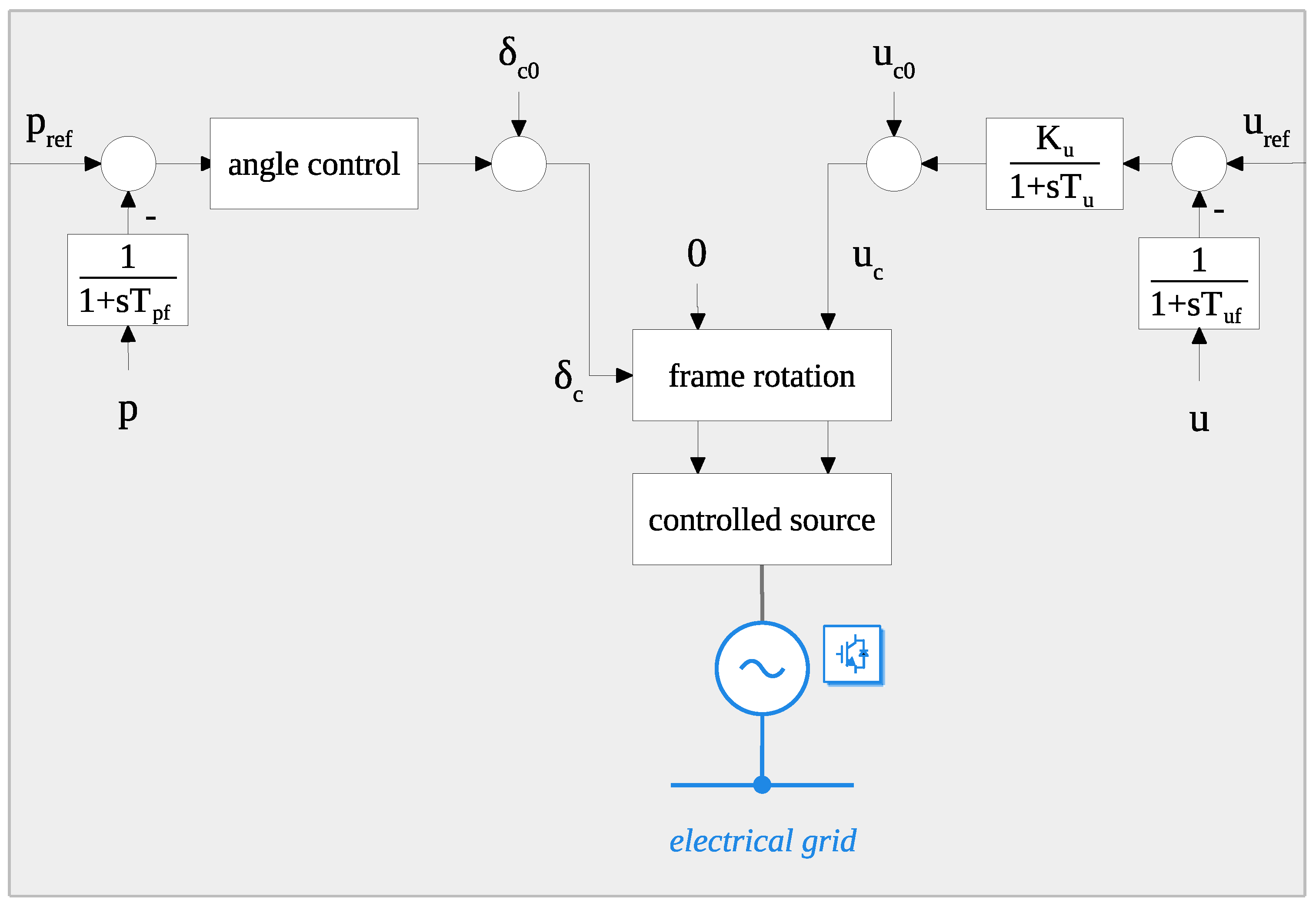
2. Grid-Forming Models for Phasor RMS Simulations

The control schemes which belong to the category of grid-forming are various. Different control schemes and variations have been in fact studied and proposed in the literature [17,18,19,20,21,22,23,24]. Two of the most common grid-forming controls are the virtual synchronous machine (VSM) and the droop-based control. The VSM can be found in a variety of control schemes and variations [25,26,27,28,29], and it is based on the emulation of the swing dynamics of the synchronous machines. The droop-based control was originally designed for converter-dominated microgrids and it provides grid-forming functionalities through droop regulators for voltage and frequency [30,31,32]. The grid-forming control considered in this work is represented in Figure 1. The angle control can implement either a virtual synchronous machine scheme (Figure 2a) or a power-synchronization control (Figure 2b). In the diagram, u c and δ c are, respectively, magnitude and angle of the converter voltage; u ref and p ref are the references for terminal voltage and active power; u and p are the voltage and the power measured at the converter output; ω n is the rated angular frequency; H is the time constant of the integral action responsible for the realization of the inertial effect, while R is the gain applied on the frequency deviation realizing the droop control for primary frequency reserve; K u and T u are, respectively, gain and time constant of the given voltage control; T pf and T uf are the time constants of the low-pass filters applied on the measurements.
The considered grid-forming control consists of two main parts, the angle control loop and the AC voltage controller. The angle control provides the reference angle δ c for the internal frame transformations of the converter, and it realizes the fundamental capabilities of the grid-forming control. For the VSM, the power-angle control implements the emulation of the swing dynamics of synchronous machines, and it includes a droop control on the frequency error. The integrator time constant realizes synthetically the inertial effect physically provided by synchronous machines. The coefficient of the droop control is instead equivalent to the frequency droop R of the turbine/governor connected to synchronous machines. In the droop-based control, the power-angle control implements a simple droop control on the deviation of the measured active power from the reference value, realizing the intrinsic synchronization mechanism without the provision of any inertial effect. It can be then easily demonstrated that the two considered formulations of virtual synchronous machine and power-synchronization control become equivalent when considering H = 0 and K i = ω n R . The AC voltage controller provides the reference magnitude u c of the voltage at the converter output for the internal generation of the modulation index, and it implements a simple droop control on the deviation of the voltage measured at the converter terminal from the reference value. Since the simulation model considered in this work is a dynamic model formulated in the phasor RMS domain, the output variables u c and δ c respectively determined by the two main control loops directly provide the real and imaginary parts of the controlled voltage expressed in the common dq0 rotating frame of the system. The converter control also contains an intrinsic dependence on the local measurement of electrical quantities such as voltage, current, and power. For that, low-pass filters (LPF) are often added to filter out the noise, to avoid attaching to harmonics, and to limit signal jumps. The measurements of voltage and active power are included in the mathematical model passing the measured electrical quantity through a first-order LPF with a given cut-off frequency. From the point of view of model implementation, the equations describing the mathematical model of the overall power system are typically referred to as a common per unit system with base power S b = 100 MVA. The equations describing the model of the interfaced generation source are instead usually expressed per unit of the rated power S r of the converter. It is, therefore, necessary to have a base change as conversion between the two per unit systems.
The considered grid-forming model does not represent the DC side of the converter and it does not include fast inner control loops for current and voltage regulation. These assumptions were considered in the work since they are not expected to have a significant impact on the frequency dynamics and generally on the slow transients of the system, which are the main focus of the presented investigations.
The phasor RMS model used in this work is developed in the power systems analysis tool NEPLAN [33]. The validation of the model to the specific purposes of the study is made comparing the phasor RMS implementation with a detailed EMT dynamic model developed in the specialized toolbox Simscape of MATLAB/Simulink [34]. The results are reported for comparison in Figure 3. It can be seen that a difference exists between the RMS and the EMT implementations. However, the results of the simulation in the two time domains indicate a substantial match for the considered events and time scales. For investigations of frequency dynamics and slow transients, the phasor RMS models of grid-forming converters appear therefore to be appropriate.

3. Frequency Dynamics of a Fully Non-Synchronous Autonomous System

The main purpose of this section is the identification of the factors which can have a critical impact on the frequency dynamics of an autonomous power system with 100% converter-interfaced generation. These factors can be identified referring to a small-signal model of the system and considering the representative case of coupled oscillators. The general case of multiple grid-forming converters interconnected between each other is reduced to a simple equivalent representation, focusing the analytical approach for the derivation of specific considerations about the frequency dynamics of a fully non-synchronous autonomous system operated with grid-forming technologies.

3.1. Identification and Study of Critical Factors

The general case of an autonomous system with multiple oscillating grid-forming units can be studied as a system composed by pairs of coupled oscillators (Figure 4a), and then focusing the attention on a generic pair i-j of oscillating sources (Figure 4b).
The active power exchanged between i and j can be expressed as:
p i j = U i U j Y i j cos   δ θ i j
where the difference between the two phase angles δ i and δ j is indicated as δ for compact notation. In (1), θ i j is the angle of the complex impedance Z ˙ i j representing the network interconnection between the two oscillators:
Z ˙ i j = R i j + j X i j = Z i j e θ i j
This representation is general and it takes into account the resistive-inductive nature of the grid interconnections which typically characterize small autonomous electric systems. It is also important to note that the total impedance Z ˙ i j between the coupled oscillators i and j can include the impedances of the physical components interconnecting the two elements and the impedances which can be virtually realized by the corresponding control systems. For the study of small-signal deviations, the expression of the active power in (1) can be linearized around an initial steady-state operating point characterized by δ 0 as follows:
Δ p i j = p i j δ | δ 0 Δ δ = U i U j Y i j sin δ 0 cos θ i j + cos δ 0 sin θ i j Δ δ
and then:
Δ p i j = U i U j Y i j sin   ( θ i j δ 0 ) Δ δ = K s Δ δ
The factor K s can be referred to as the synchronizing coefficient between the oscillators i and j, and it can be regarded as the expression of the elastic restoring torques between pairs of coupled oscillating elements which enforce the synchronization [35].
The mathematical representation of the two oscillators in Figure 4b can be formulated with different degrees of complexity and detail. Since the purpose of the work is the investigation of the frequency dynamics of the system, an analytical approach can be focused on the equations governing the power-angle control of the considered sources. Proceeding in this way, the system in Figure 4b can be described by the following mathematical system of differential-algebraic equations:
d Δ ω j d t = 1 2 H j Δ p ref j Δ p j i S b S r j 1 R j Δ ω j
d Δ δ j d t = ω n Δ ω j
d Δ ω i d t = 1 2 H i Δ p ref i Δ p i j m S b S r i 1 R i Δ ω i
d Δ δ i d t = ω n Δ ω i
Δ p i j m d t = 1 T pf Δ p i j Δ p i j m
Δ p i j = K s Δ δ i Δ δ j
Δ p j i = K s Δ δ j Δ δ i
where the active power exchanges Δ p i j and the factor K s are given by (4). In the mathematical representation of the oscillator i, Equation (9) has been additionally considered. This equation represents the low-pass filter of the active power measurement included in the grid-forming control (Figure 1). The mathematical model also considers the required conversion between the common per unit system with base power S b = 100 MVA and the local per unit system of the element model with rated power S r as base power. For the study of the system given in Figure 4b, it is possible in fact to note that the oscillator i represents the specific grid-forming converter, while the oscillator j describes a generic swinging element characterized by a first-order dynamic. For the sake of a more straightforward notation, the quantities related to the generic swinging element will be denoted with the subscript g, while for the grid-forming converter the subscript c will be used. It is then possible to express the small-signal model of the system (5)–(11) in a state-space formulation where the matrix A and the state vector Δ x are given by:
A = 1 2 H g R g K s 2 H g S b S g 0 K s 2 H g S b S g 0 ω n 0 0 0 0 0 0 1 2 H c R c 0 1 2 H c 0 0 ω n 0 0 0 K s T pf S b S c 0 K s T pf S b S c 1 T pf Δ x = Δ ω g Δ δ g Δ ω c Δ δ c Δ p m
The first two rows of the matrix A correspond to the dynamic representation of the generic swinging element, while the remaining rows correspond to the small-signal model of the angle control of the grid-forming element (Figure 4b). From the coefficients of the matrix, it can be immediately observed that they depend on:
  • rated power of the grid-forming converter ( S c );
  • inertial effect of the grid-forming angle control ( H c );
  • frequency droop of the grid-forming angle control ( R c );
  • time constant of the low-pass filter on the active power measurement ( T pf );
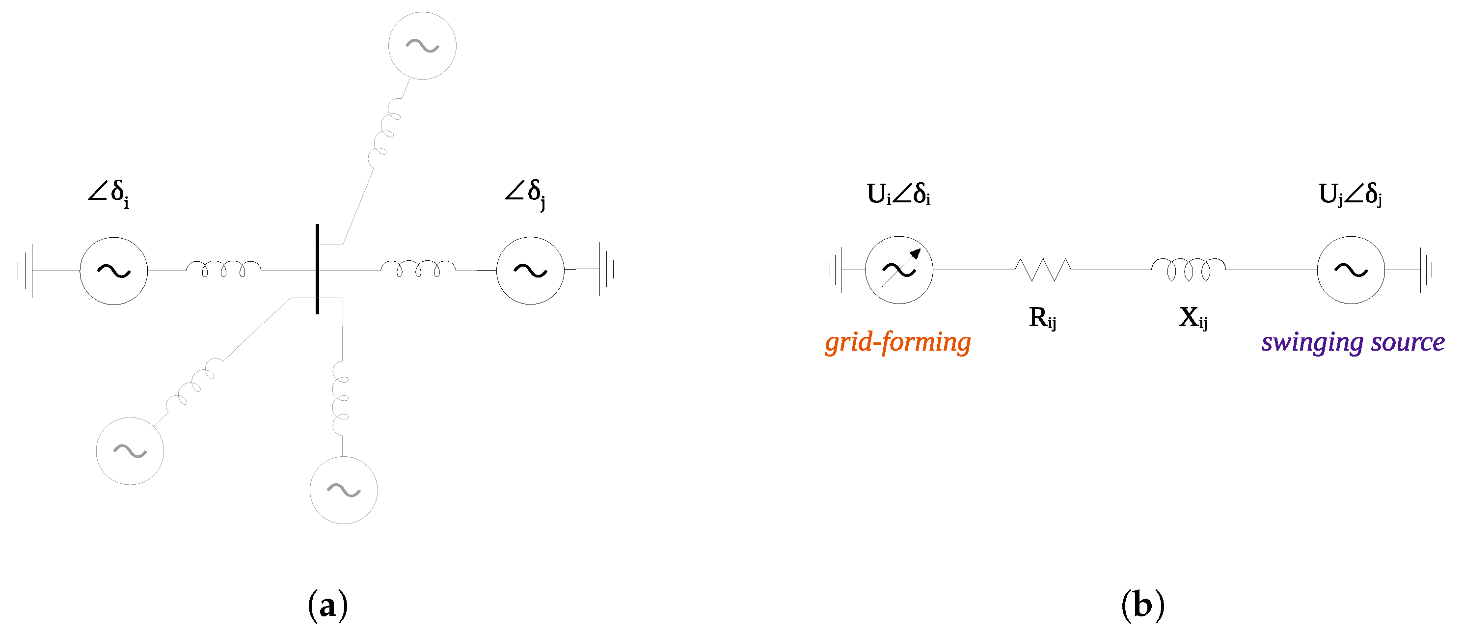
  • the characteristics of the interconnections ( K s );
  • strength of the network ( S g ).
The computation of the eigenvalues of the matrix A can be performed to provide a deeper insight on the possible impact of the factors listed before. In particular, the calculation of the eigenvalues can be iteratively repeated for a parametric analysis with a sweep of the identified relevant parameters. For the analysis, the parameter S g characterizing the strength of the network is fixed to three values: infinite bus, 1000 MVA, and 10 MVA. The last two values can cover two possible conditions of autonomous electrical systems, high strength (relatively large network, several oscillating sources) and low strength (small network, limited number of oscillating sources). The infinite bus case is considered only for the sake of comparison. All the other parameters are related to the grid-forming converter: for them, a sweep in a typical range of values is considered. The results of the computations are summarized in Figure 5.
From the results, a first general observation is that the strength of the grid S g has the expected impact on the impedance magnitude and angle, and also on the sensitivities of the grid-forming droop and of the measurement LPF time constant. The sensitivities of inertial effect and converter rated power are instead marginally affected by the value of S g . From the plot of Figure 5a, it is possible to notice that an increase of the inertial effect has a negative impact on the stability of the system. It can be however observed that a further increase of the inertia H c of the grid-forming eliminates the instability phenomenon, as is indicated by the eigenvalues of the system coming back in the left-hand side of the plane. From the plots of Figure 5b,d, it can be seen that increasing the grid-forming droop R c and the time constant of the active power measurement filter T pf can definitely determine the instability of the system. From the plot of Figure 5c, it can be immediately observed that small grid-forming converters can make the system unstable: since the grid-forming must act as a reference for the system, a converter with a small rated power might not be strong enough to contribute positively to the frequency dynamics. From the plot of Figure 5e, it is possible to notice that an increase of the impedance modulus has a positive impact on the stability of the considered oscillators system. This result suggests that a grid-forming converter close to another oscillating source might experience difficulties for successfully operating in stable conditions. The plot of Figure 5f examines the sensitivity of the resistive-inductive nature of the network interconnections, sweeping from a purely resistive grid (impedance angle 0 ) to a purely inductive grid (impedance angle 90 ). It can be observed that the presence of a resistive component has a positive impact on the stability of the system, contributing to a relevant increase of the damping.
In summary, the small-signal model of the controls governing the frequency dynamics of a multiple oscillators system and the parametric analysis of the selected parameters indicate a specific impact on the dynamics of fully non-synchronous autonomous networks, suggesting a potential instability of the system under particular conditions. Certainly, combinations and variations of the identified critical factors can determine specific results and further considerations. This aspect will be addressed in the analysis of the case study discussed in Section 5.
The root cause of the observed instability can be ultimately identified in the time constant T pf of the LPF applied on the active power measurement of the converter. This is a known issue with LPF and active power control in grid-forming converters [36,37,38,39]. For a better illustration of this issue, the simple case of a single oscillator connected to an infinite bus can be used as illustrative example (Figure 6).
In the diagram, the feedback pathway includes the representation of the network interconnection with the coefficient K s and the effects of the LPF on the active power measurement. The components of synchronizing and damping coefficients due to network interconnection and low-pass filter can be isolated employing a similar approach to the one followed in the case of synchronous machines for the change in the electrical torque due to field flux variations caused by angle changes [40]. The open-loop transfer function between Δ p m and Δ δ in the feedback pathway of the model can be expressed by:
Δ p m Δ δ = K s G L P F = K s ω f ω f + s
where ω f = 1/ T pf .
The transfer function in (13) can be regarded as the variation of Δ p m caused by a change in the angle Δ δ . The expression in (13) can be rearranged multiplying numerator and denominator by ω f s , resulting in:
Δ p m = K s ω f 2 ω f 2 s 2 Δ δ K s ω f ω f 2 s 2 s Δ δ
Recalling that the derivative of the angle is the frequency through s Δ δ = ω n Δ ω and substituting s = j ω in (14), the variation of Δ p m caused by a change in the frequency Δ ω can be expressed by:
Δ p m Δ ω = ω n K s ω f ω f 2 + ω 2
which represents the component of the damping coefficient due to network interconnection and low-pass filter. The term given in (15) immediately indicates that the contribution provided by the feedback component is negative, causing therefore a reduction of the damping provided by the whole control. The reduction is clearly due to the presence of the LPF on the feedback pathway of the system, and it is affected by the cut-off frequency ω f of the filter. The magnitude of the reduction is also determined by the given oscillation frequency ω and by the coefficient K s . Recalling the dependence of the synchronizing coefficients, it can be observed that small rated powers and close electrical distances would result in severe damping reduction, possibly threatening the stability of the system. These two factors have, therefore, an additional specific impact on the power–frequency dynamics, referring in particular to the damping characteristics of the system.

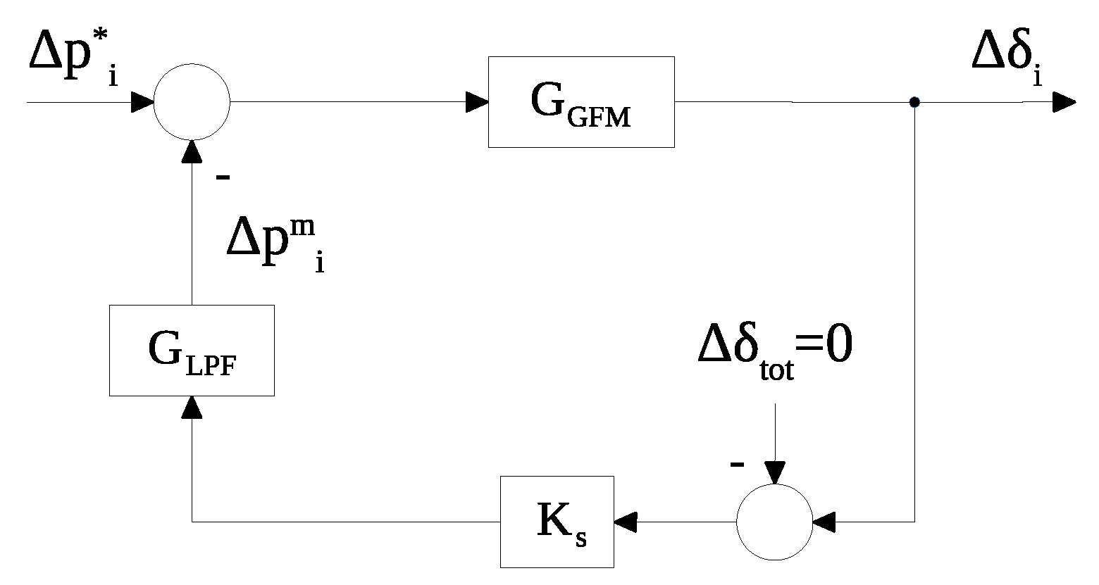
3.2. Discussion about Stability and Damping

The factors identified in the previous sections are summarized in Table 1. The number of oscillating grid-forming units connected to the system, their mutual distances and their rated powers are main aspects which can affect the dynamic interactions during a frequency transient. The characteristics of the grid-forming controls governed by specific parameters such as the inertia time constant and the virtual impedances are also factors to consider, since they certainly affect the power–frequency dynamics of the system. As observed in the previous analysis, all these factors can have a critical impact on the system stability. The aspects related to damping and oscillatory stability of power systems dominated by power converters are addressed in several works [36,37,38,39,41,42]. In [41], it is remarked that grid-forming controls should be properly implemented, as they could result in a poorly damped closed-loop system. In [36], the effects related to LPF within the active power loop of the converter control are analytically investigated and recognized as a potential source of a critical lack of damping, leading to instability and loss of synchronization. Other works and research propose specific solutions to this problem [37,38,39]. More generally, the issue of damping provision by power converters is widely discussed in several papers and technical reports [42,43,44,45,46,47,48,49,50,51]. While this article focuses on the frequency stability of an autonomous system operated with multiple grid-forming converters, other various aspects related to the dynamic interactions between grid-forming converters are addressed from different points of view and hierarchical control levels [52,53,54,55,56,57,58,59,60,61,62].

4. Design Principles for Fully Non-Synchronous Autonomous Systems

4.1. Reference Hypothesis

The design of an autonomous system completely operated with interfaced generation is an aspect which has been explored only in very few cases, often in the context of pilot projects and experimental test cases. In general, the design objectives for an autonomous system with 100% converter-interfaced generation can be various and are dependent on the given characteristics of the system. In this work, a general design approach is proposed. The method is a three-step procedure and it is focused on fundamental aspects of the frequency dynamics, targeting both steady-state and transient frequency performance as design principles. As an initial step, it is fundamental to define a specific design hypothesis for the system under planning. The purpose of this design objective is the determination of a reference power imbalance Δ p * , which will be used in the next steps of the design process. The definition of a reference incident might be made according to several methods and criteria. For instance, a possible design hypothesis for Δ p * could be the loss of the biggest generation unit in the system, adopting an N-1 criterion. Another possibility could be to assign Δ p * in the range of 3–5% of the maximum system load: a power imbalance in that range is in fact already considered as a large disturbance for the system [63]. More advanced techniques might be based on probabilistic methods, including considerations about the availability of the generation sources interfaced by the converters. In this work, the approach based on the designation of the reference power imbalance as percentage of the maximum load of the system will be considered, fixing Δ p * to 5% of the maximum load.

4.2. Total Required Grid-Forming

One first point which should be surely addressed is how much grid-forming power is required in an autonomous system. This point can be subjected to several different constraints and addressed from several points of view. For instance, some works indicate that there is a minimum amount of non-synchronous generation sources with grid-forming capabilities required to guarantee the stability of the system [5,8,64]. To keep the design process simple, the determination of the total required grid-forming is exclusively derived for the realization of the given steady-state conditions on frequency dynamics, leaving the consideration related to transient performance to the other design step. The design principle will be then focused, in this case, on the realization of proper active power sharing between the generation sources. This will also give an idea of the possible proportion between grid-forming and grid-following units in the system. For the determination of the total rated power, which must summed up by all the converters with grid-forming capabilities, it is necessary to fix two design targets: the frequency deviation at steady-state Δ f s * which should correspond to the reference power imbalance Δ p * , and the frequency droop gain R which will govern the power sharing of the grid-forming sources. The target value of the frequency deviation at steady-state Δ f s * can be fixed according to the grid code specifications existing for the autonomous system under design. The value of the frequency droop R is instead typically assigned in the range from 1 to 10% of the rated power of the element: if the per unit frequency droop will be assumed equal for all the generation sources participating in the primary reserve with the grid-forming control, a given power imbalance in the system will be thus shared between them proportionally. For the design, it is assumed that the other interfaced generation sources are operated as grid-following without implementing any frequency droop control. This is a conservative assumption, since in many cases grid-following units can participate in the primary reserve while operating in frequency sensitive mode. For an autonomous system where the generation sources are limited, it is, however, reasonable to think that some units will not be always available for participation in the primary frequency control. For fixed values of the reference power imbalance Δ p * and of the target frequency deviation at steady-state Δ f s * , the total required power S tot * can be expressed as:
S tot * = f n R Δ p * Δ f s *
Using (16), it is possible to determine the minimum total required amount of grid-forming converters to match the steady-state performance design. The number of grid-forming converters and the subdivision of the total required power between them are aspects which can be determined according to additional constraints and further considerations. For that, some insights will be provided by the investigations of the critical factors for frequency dynamics described in Section 5.

4.3. Total Required Inertia

Another point which should also be considered in the design concerns the transient performance of the power–frequency dynamics of the system. The main aspects are the total required amount of inertial effect, the maximum/minimum allowed instantaneous frequency deviation and the maximum allowed absolute frequency rate. These aspects are interrelated, since the inertial effect taking place in the very first instants of the transient affect both the frequency rate and the instantaneous deviation of the frequency. The design principle can be then focused on the realization of a predefined inertial effect, synthetically provided by the interfaced generation sources which will be operated as grid-forming. For the design, it is assumed that the other interfaced generation sources operated as grid-following will not implement any synthetic inertia control. Like the case of primary reserve, this assumption is conservative because grid-following units can generally provide synthetic inertia through specific additional controls. For the determination of the total amount of inertial effect which must be provided by the converters with grid-forming capabilities, the approach can be based on the concepts of the center of inertia and aggregated swing dynamics. Contrarily to large interconnected power systems, in the case of autonomous networks, it is reasonable to assume that the dynamics of all the oscillating elements can be concentrated at the center of inertia, with a unique coherent frequency for the whole system. Two alternative design targets can be then fixed: the total required inertia can be in fact determined either considering the maximum allowed frequency rate or the maximum/minimum allowed instantaneous frequency deviation. While for large interconnected systems both targets would likely require a complex and elaborated design procedure, for small autonomous power systems the design can be easily kept simple in both cases: if the target is either the limitation of the frequency rate or the containment of the instantaneous frequency deviation, the possibility of assuming the dynamics of the system concentrated at the center of inertia makes both design targets viable. In this work, the total required amount of inertial effect will be determined assuming the maximum frequency rate as design target. The alternative of considering the instantaneous frequency deviation is discarded: since the frequency dynamics of a multiple grid-forming autonomous system can be essentially characterized by a first-order dynamics, no significant differences between instantaneous and steady-state frequency deviations are expected, and therefore the inertia would only have a limited effect on this design target. For fixed values of the reference power imbalance Δ p * and of the target frequency rate ρ max * , the total required inertial effect can be expressed in terms of total inertia constant H tot * as:
H tot * = f n Δ p * 2 ρ max * S tot *
Using (17), it is possible to determine the minimum required amount of inertial effect which should be provided by grid-forming converters to meet the specific transient performance design. It is worth noting that the inertial effect synthetically provided by grid-forming converters has also a particular impact on the synchronization mechanism between the oscillating grid-forming generation sources, and consequently on the oscillatory characteristics of the system. For that, some additional insights will be provided by the investigations of the critical factors for frequency dynamics described in Section 5.

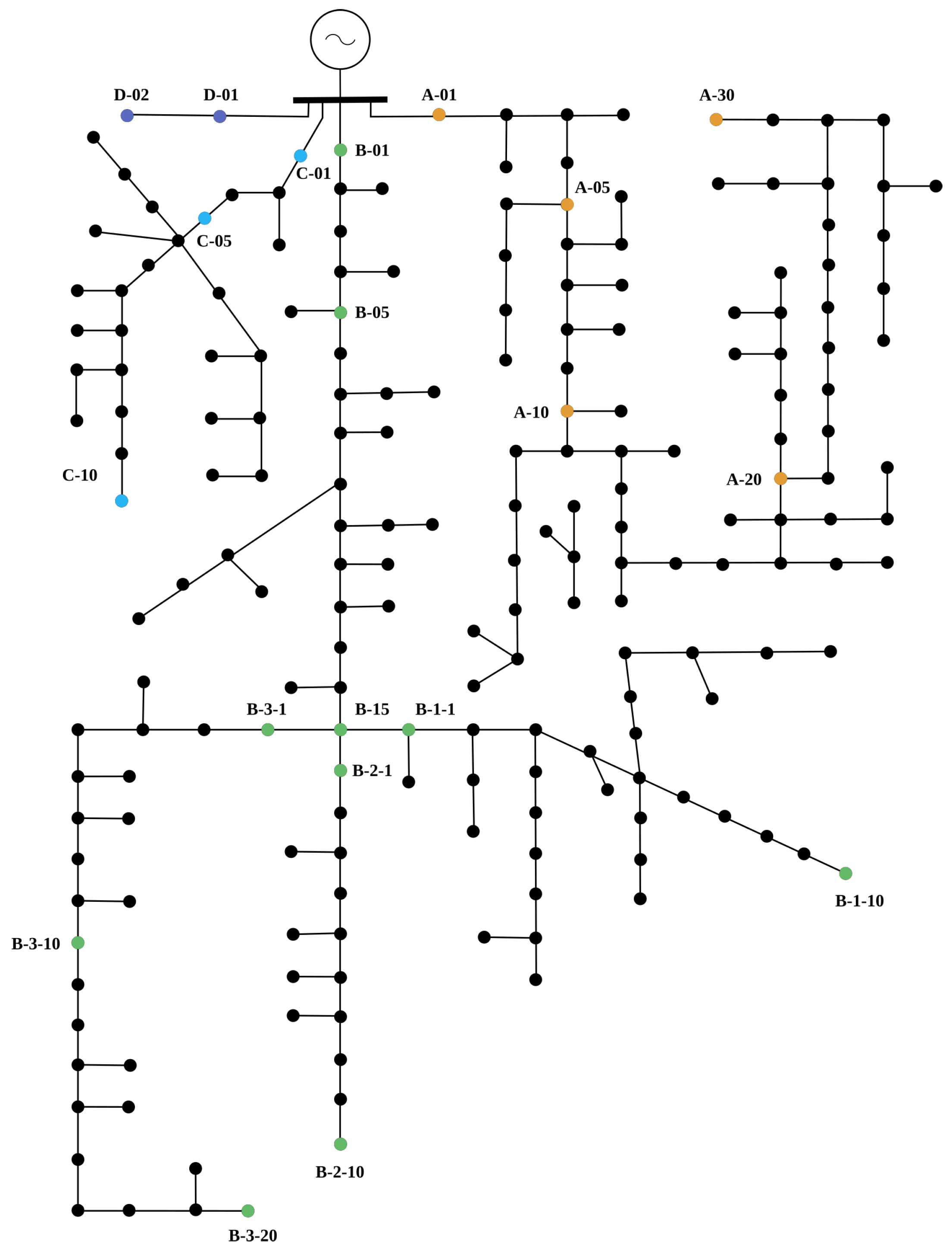
5. Case Study: Application to the Existing Power System of a Mediterranean Island

The system considered as case study is the medium voltage network of Pantelleria, an island in the Mediterranean sea. The total demand of the island strongly depends on the period of the year, and it varies from a minimum of around 4 MW to a maximum of around 8 MW. The load demand is currently supplied by a thermal generation power plant, composed by diesel generators and located close to the urban center. The island is therefore dependent on external sources of energy. The power is delivered to the loads through four main feeders, all departing from the thermal power plant. The total lengths of the medium voltage feeders span from 14 km for the longest lines to 4 km for the shortest. The lines are mainly cables, with resistance in the range 0.33–0.47 Ω /km, reactance 0.23–0.31 Ω /km and capacitance 0.1–0.24 μ F/km. There are only a few photovoltaic plants installed in the system, mainly in the urban center: the total active power is around 300 kW, so the photovoltaic plants represent just a minor generation share over the total load of the island. A schematic outline of the system is shown in Figure 7.
The autonomous system of the island is then imagined in future operating conditions, characterized by the complete phase out of all synchronous machines of the diesel power plant and the corresponding integration of the necessary amount of renewable power generation to guarantee the load supply. In the considered scenario, the electric system of the island would be therefore powered by 100% converter-interfaced generation. This scenario is then formulated in several different potential combinations and configurations. The interfaced generation sources integrated in the system of the island will vary in number and rated power, they will be assumed to be installed at different locations across the system, and they will either implement a grid-following or a grid-forming control, considering also different tuning of the control parameters. All the particular combinations and configurations will be adapted depending on the aspects to be investigated. For an efficient management of all the various system configurations and simulation cases, the handling of the calculations is automated with a stand-alone application written in C#. The utility accesses externally the functionalities of the powers systems analysis software NEPLAN [33] by calling the available APIs of the software. The application makes then possible to manage all the elements and the models of the system in a custom-defined and automatic way, run consecutive simulations programmatically and post-process the results for statistics. For the simulations, the power system of the island is represented with a positive sequence RMS dynamic model. The models of the converter-interfaced generation sources are implemented according to the control structure presented in Section 2, and they are developed as user-written dynamic models with SYMDEF (SYMbolic DEFinition), proprietary modeling language of NEPLAN. In all the considered configurations, the power system is simulated in perturbed conditions, characterized by an uniform disturbance identically applied to all the loads of the network. For that, a step change of Δ p d = 1% in the initial active power of all the loads is applied in the time-domain simulations. The value of the load step is selected as a relatively small perturbation for the system, considering that a load change in the range 3–5% is already regarded as a large disturbance [63]. Moreover, the approach of considering a uniform distributed disturbance for all the loads allows to investigate the effects of different percentages and locations of non-synchronous generation sources with inertial and damping capabilities on the system dynamics [65]. For the simulation model, the parameters have the following default values: H = 2 s, R = 0.05 pu, K u = 1 pu, T u = 0.001 s, X v = 0.1 pu, ω f = 100 rad/s.

5.1. System Design for Frequency Dynamics
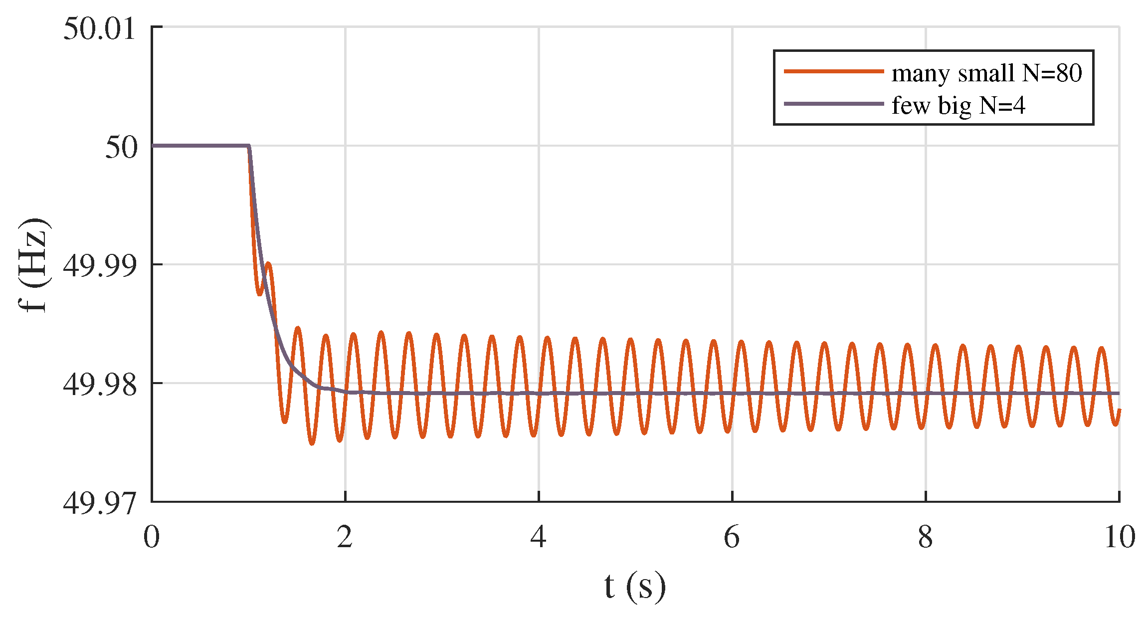
The design of the power system of Pantelleria island for a future scenario with 100% converter-interfaced generation can be made according to the methods introduced in Section 4. The maximum load of the system is P max = 8.1 MW, observed in the summer season due to the influx of tourists. The reference power imbalance Δ p * can be then calculated as 5% of the maximum load, resulting in Δ p * = 0.05 · P max = 400 kW. For the frequency control, it is decided to fix the frequency droop to 5% for all the generation sources participating in the primary reserve. The aggregated frequency droop R is thus equal to R = 5/100 = 0.05 pu, in per unit of the given grid-forming converter rated power. The design targets are the steady-state frequency deviation, fixed to Δ f s * = 50 49 = 1 Hz, and the maximum absolute value of the frequency rate, fixed to ρ max = 5 Hz/s. Applying (16) with all the previous values for the design targets, it is possible to calculate the total amount of rated power S tot * which should implement grid-forming capabilities as:
S tot * = f n R Δ p * Δ f s * = 50 × 0.05 × 0.4 1 = 1 MVA
Applying (17), it is possible to calculate the total amount of inertial effects in terms of inertia constant H tot * which should be guaranteed in the system approximately as:
H tot * = f n Δ p * 2 ρ max * S tot * = 50 × 0.4 2 × 5 × 1 = 2 s
The calculated value of S tot * represents the minimum total amount of grid-forming converters required to guarantee the steady-state frequency performance, while the calculated value represents the total inertial effect which should be provided by the grid-forming converters to meet the specific transient performance assumed as design target.

5.2. Impact of Size

The impact of the size of grid-forming converters is investigated with the following system configuration: only two interfaced generation sources are operated as grid-forming units, while all the remaining interfaced generation sources are controlled as grid-following. The two grid-forming units are connected at the nodes A-01 and A-05, at locations close to the same feeder (Figure 7). Different combinations of the rated powers of the two grid-forming converters are examined. The first combination considers two big grid-forming units, both with rated power S r = 4 MVA. The second combination considers instead two relatively small grid-forming units, with rated power S r = 1 MVA each. Finally, the third combination considers a big and a small grid-forming units, with S r = 4 MVA and S r = 1 MVA, respectively. In this analysis case, the size of S r = 4 MVA is considered to be a big generation unit in comparison with the total load of the system ( P max = 8.1 MW), while the size of S r = 1 MVA is assumed to be instead a small generation unit as conventionally equal to or smaller than about 10% of the total load. The simulation of the described system configurations give the results shown in Figure 8. The results indicate that small grid-forming units in an autonomous system might lead to a detrimental oscillatory instability. In fact, it can be noticed that two small units are not capable of realizing a successful synchronization in the system. In other words, the small sized grid-forming units are not strong enough to impose the frequency of the voltage at their terminals, and having comparable sizes, they will “compete” with each other for synchronism without success. It can also be observed that it is not only the rated power of the single oscillating grid-forming converter which matters, but it is rather the ratio between the rated powers of the grid-forming units involved in the oscillations which can have a significant impact. In the case of one big unit and one small unit, the system response is in fact unstable. The phenomenon of the oscillatory instability is mitigated and eventually compensated for by bigger sizes of the grid-forming converters: for the given system configurations with two big sized grid-forming units, the system response is stable. In that case, the oscillating units are strong enough to sustain a reference frequency for the terminal voltage, thus contributing to a successful synchronization process.

5.3. Impact of Number

The impact of the number of grid-forming converters is investigated with the following two configurations. In the first configuration, only four relatively big converter-interfaced generation sources are connected to the network, representing the whole generation of the system. All four converter-interfaced generation sources implement grid-forming capabilities, and they have a rated power of S r = 2 MVA each. The four grid-forming units are assumed to be connected in the middle of the four feeders of the network, located not too close to each other. In the second configuration, 80 small converter-interfaced generation units are distributed all across the autonomous system, with a rated power of S r = 100 kVA each. All the generation units are controlled with the grid-forming scheme: almost every medium voltage substation of the network has, therefore, a generation source with grid-forming control. In both configurations, the grid-forming units cover the total load demand of the island, providing also the same amount of inertial effect. The two configurations are then equivalent from the point of view of generated power, total rated power and total inertial effect. The results of the time-domain simulations are shown in Figure 9. It can be immediately observed that an high number of small grid-forming converters puts the system at the edge of the stability, generating sustained oscillations in the transient response after a perturbation. The system does not experience the oscillatory instability in this case because the distribution of oscillating grid-forming units across the grid is so dense that they are very close with each other, and therefore able to reach the synchronism. If instead the grid-forming capabilities are provided by a few units concentrated in the network, the dynamic behavior of the system is stable and exhibits better transient performance. The results confirm then the observations made about the impact of the rated power of grid-forming units, indicating the opportunity of having only a few big generation units operated as grid-forming, instead of many small oscillating grid-forming distributed in the system.

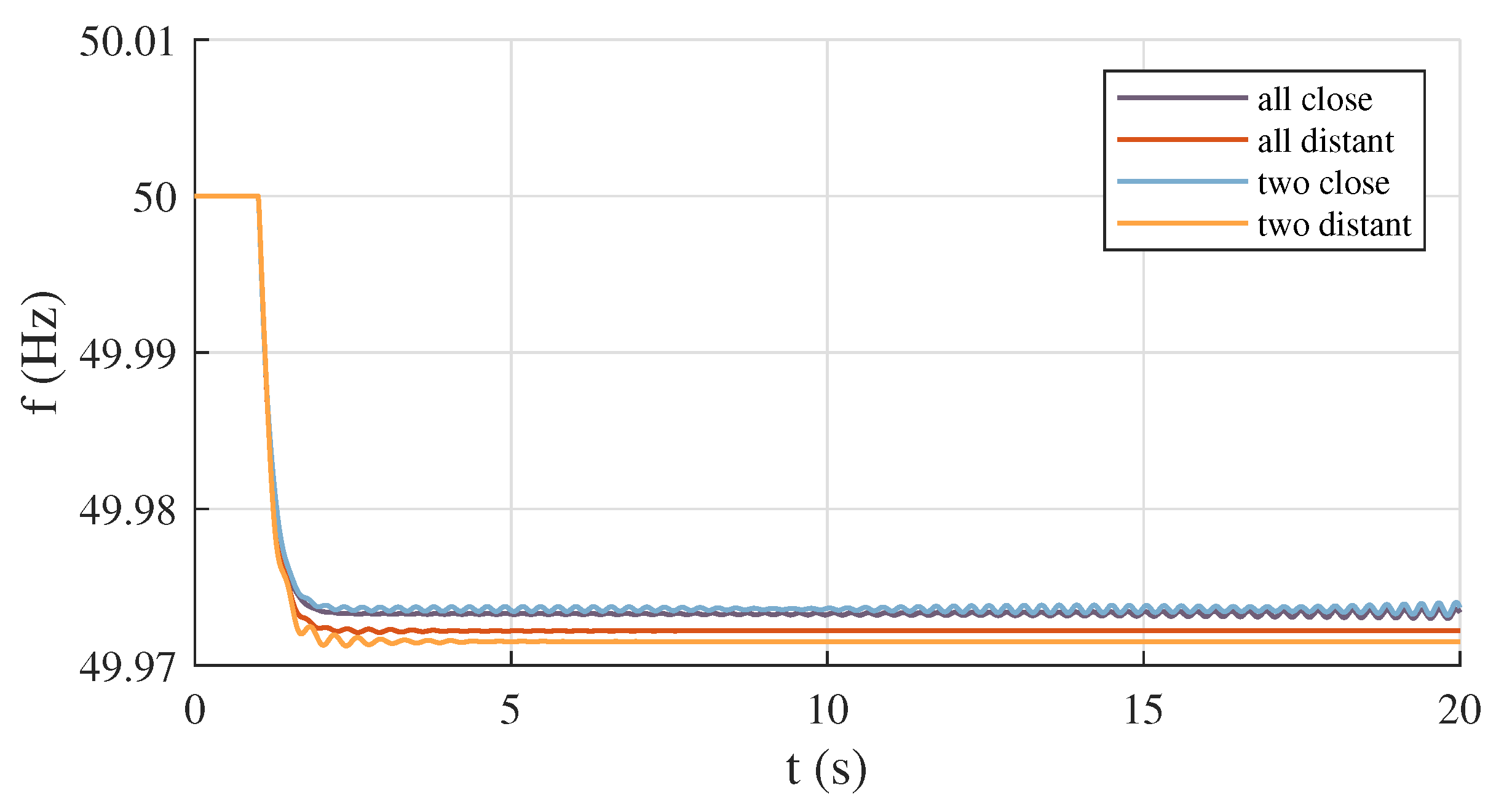
5.4. Impact of Location

The impact of electrical distances and mutual locations between grid-forming converters is investigated with the following system configurations. The first configuration considers three grid-forming units installed at the most close locations in the grid: the selected nodes with the grid-forming controls are then A-01, B-01 and C-01 (Figure 7). The second configuration considers the same three grid-forming units installed at the most distant locations between each other: the selected nodes are in this case A-30, B-3-20 and C-10. The third configuration considers two of the three grid-forming units installed close to each other, while the third grid-forming unit is connected far from the other two. The selected nodes are in this case A-01, B-01 and C-10. The fourth and last configuration considers two of the three grid-forming units installed at very distant locations from each other, while the third grid-forming unit is connected in an intermediate position between the other two. The selected nodes are in this case A-30, B-01 and C-10. In all the configurations, the grid-forming units have a rated power of S r = 2 MVA each. The simulation of the four system configurations give the results shown in Figure 10. The results indicate that the location of the grid-forming units can have a critical impact on the oscillatory stability of the system. It can be in fact observed that when two or more oscillating grid-forming converters are electrically close in the network, they might not be capable to realize the synchronization, “competing” with each other through sustained oscillations and eventually leading to the instability of the system. In the case of grid-forming units electrically far from each other, they can successfully reach the synchronism and the response of the system is stable. It can be additionally observed that the case of a grid-forming converter in an intermediate position between the other two grid-forming distant from each other shows some initial oscillations at the beginning of the frequency transient (yellow line in Figure 10), indicating already an alteration of the power–frequency dynamics of the system. It is clear that the location of generation sources is subject to several constraints, and it is not a factor of free decision in the system operation. However, the understanding and the considerations about the impact of electrical distances between grid-forming converters might be useful in supporting a more careful selection and design of the converters implementing a grid-forming control in autonomous power systems.

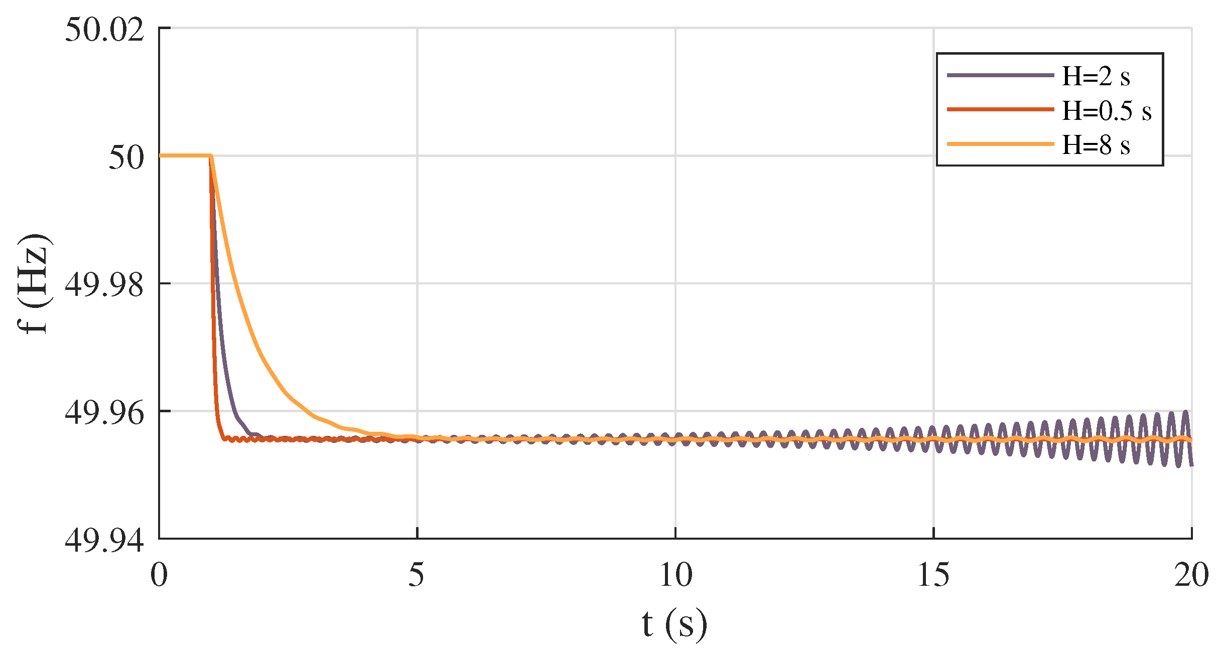
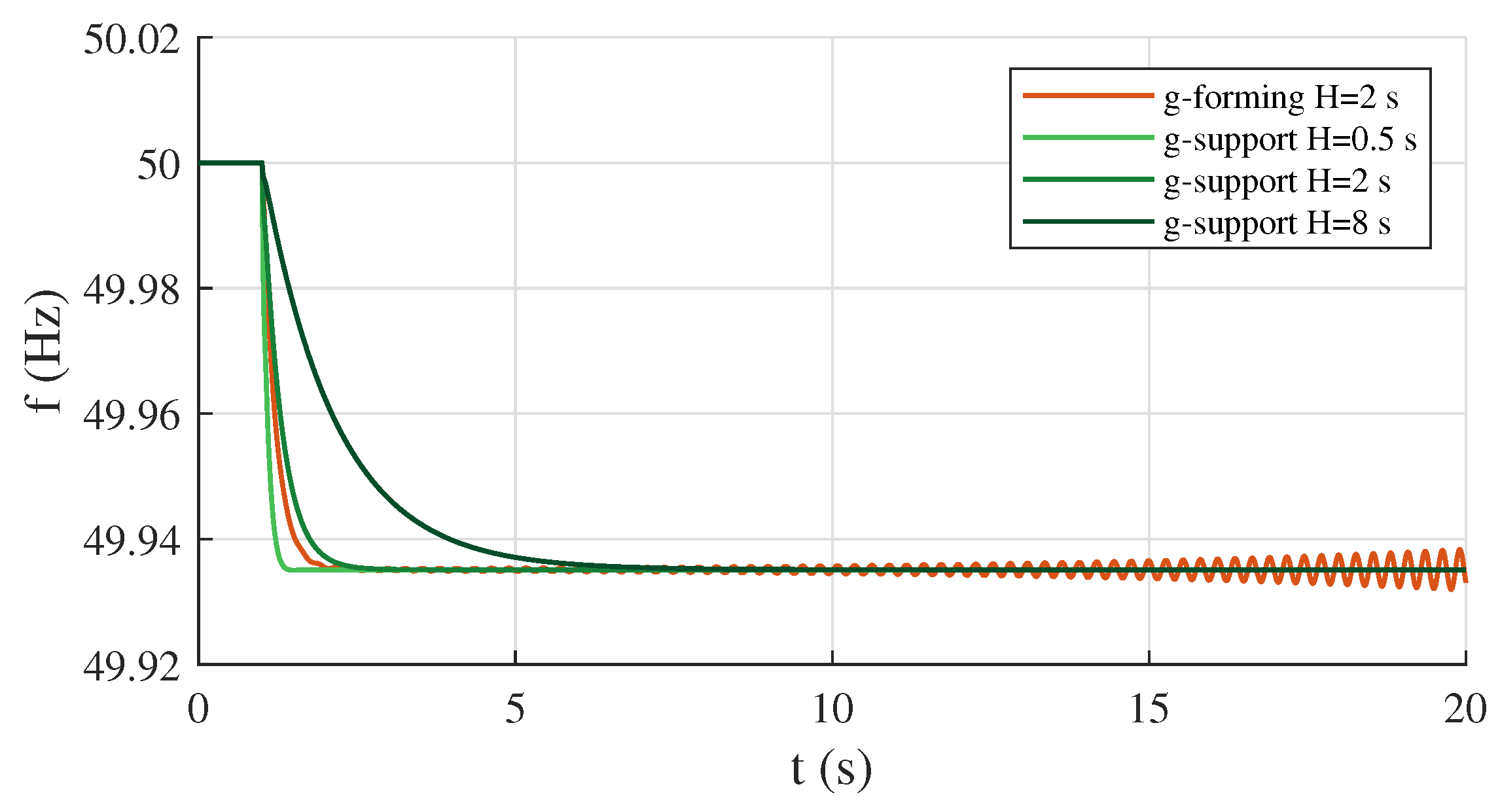
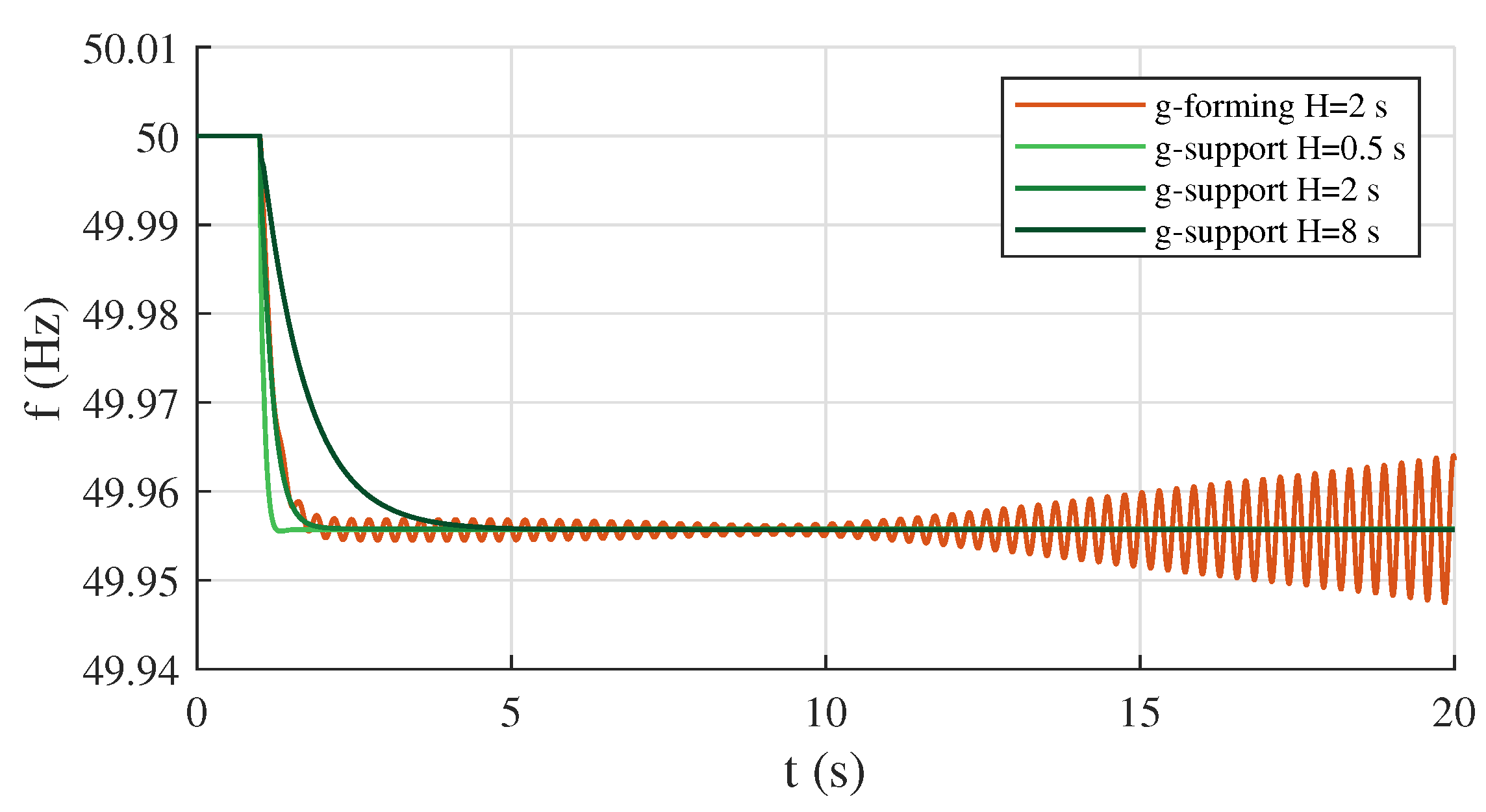
5.5. Impact of Inertial Effect

The most relevant parameter of the considered grid-forming control is the time constant of the first integrator. This parameter is in fact responsible for the realization of the inertial effect provided by the control, and it also significantly affects the inherent synchronization mechanism between grid-forming units. The impact of the inertial effect provided by the control is investigated considering again the case of three grid-forming units connected at the most close locations in the system, and performing a parametric analysis by simulating the system with different values of the inertia time constant H. The considered values are the inertia constant of the base case (H = 2 s), and then four times smaller (H = 0.5 s) and four times bigger (H = 8 s) inertia constants. The simulation results are shown in Figure 11. The base case with H = 2 s corresponds to the instability observed in the previous section, when the grid-forming units are electrically near and they swing against each other without reaching a successful synchronization. For the same system configuration, if the inertia time constant of all the grid-forming converters is reduced by reducing the constant H, the control actions become faster and more damped, realizing a swift synchronization between the oscillating units. With the reduction of the inertial effect, the implemented control approaches the zero-inertia grid-forming model proposed in [20,28], and it would also correspond to other inertia-less grid-forming schemes, such as the power-synchronization control or droop-based controls without low-pass filters [21,66]. In the simulated case, a reduced inertia time constant of H = 0.5 s can already ensure a stable transient operation of the autonomous system. If instead the inertial effect is increased by increasing the time constant H of the integrator, the phenomenon of the oscillatory instability becomes mitigated for as well. For the simulations, a value of H = 8 s has been considered. In this case, the increased inertial effect makes the control actions slower, introducing a sort of temporal margin which gives flexibility in the synchronization process between the grid-forming units. The response of the system in this case would be still oscillatory, with the tendency to stabilize. From the results, it appears the possible existence of a range of inertia time constant, where the oscillating grid-forming units with given rated powers engage themselves increasing oscillations, eventually leading to the instability of the system.
Given the recognized relevance of the inertial effect on the frequency dynamics of the system, a more detailed analysis is dedicated to the impact of this factor, considering four additional simulation cases. The configuration used to investigate the impact of different rated powers of the grid-forming units is here analyzed again, assuming different values of the inertia time constant. Two grid-forming units are then connected at relatively close locations in the grid (nodes A-01 and A-05 in Figure 7), considering different values and combinations of the rated powers. The results of the time-domain simulations are summarized in Table 2. To complete the previous considerations, it can be further observed that the reduction of the inertial effect is more effective when applied to grid-forming unit with relatively big rated power, or, in a specular way, that the increase of the inertial effect producing a temporal lag as margin for synchronization is more effective when applied to grid-forming units with relatively small rated power.
It is worth observing that the proposed methodology for the determination of the total amount of inertial effect can be effectively used for the realization of the desired design target, with the containment of the frequency rate within a given maximum value, but the oscillatory characteristics and the power–frequency control of the system can be also significantly affected. For that, more elaborated design techniques of the inertial effect could be applied.

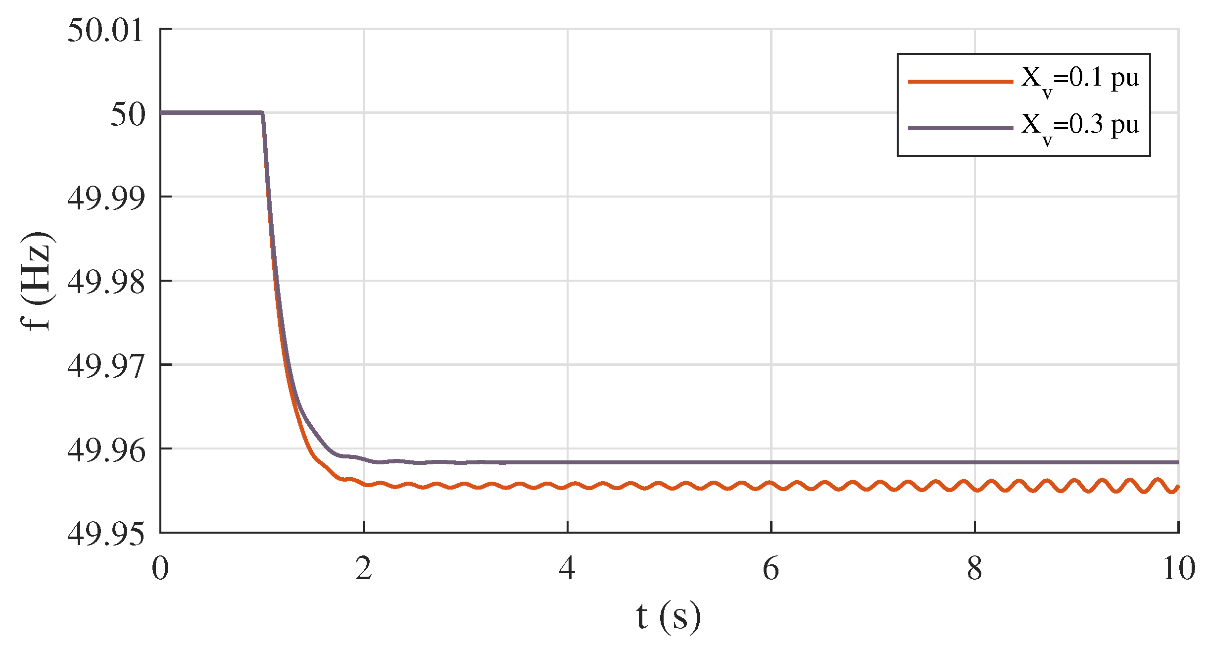
5.6. Impact of Virtual Impedance

The virtual impedance of a grid-forming scheme is another control parameter such as the inertia time constant which can have a significant impact on the dynamic response of the system [67,68,69]. As with what was achieved for the inertia time constant, the impact of the virtual impedance is investigated considering the case of three grid-forming units connected at the most close locations in the system, performing a parametric analysis with different values of the virtual impedance X v implemented in the control. The simulation results are reported in Figure 12. The base case with X v = 0.1 pu corresponds to the phenomenon observed studying the impact of location, when the grid-forming units are electrically near and they swing against each other eventually leading to the instability of the system. If the virtual impedance X v is increased, the grid-forming converters become virtually more distant, the positive effect of long electrical distances is emulated, and the power–frequency dynamics of the system becomes stable. In this case, the increased virtual impedance makes the couplings between the oscillating grid-forming units looser, enabling a more flexible synchronization process. According to the previous considerations, the increase of X v determines in fact a reduction of the synchronizing coefficients K s . This reduction however is not critical for the frequency dynamics of the system, but it rather introduces a sort of elasticity which allows the grid-forming units to successfully reach the synchronism after a perturbation. The difference observed in the steady-state frequency between the two cases with different virtual impedances is related to the self-regulating effect of the loads: the implementation of a virtual impedance modifies in fact the voltage control realized at the terminal of the converters, and consequently the loads produce different changes in the power according to the different values of the voltage.

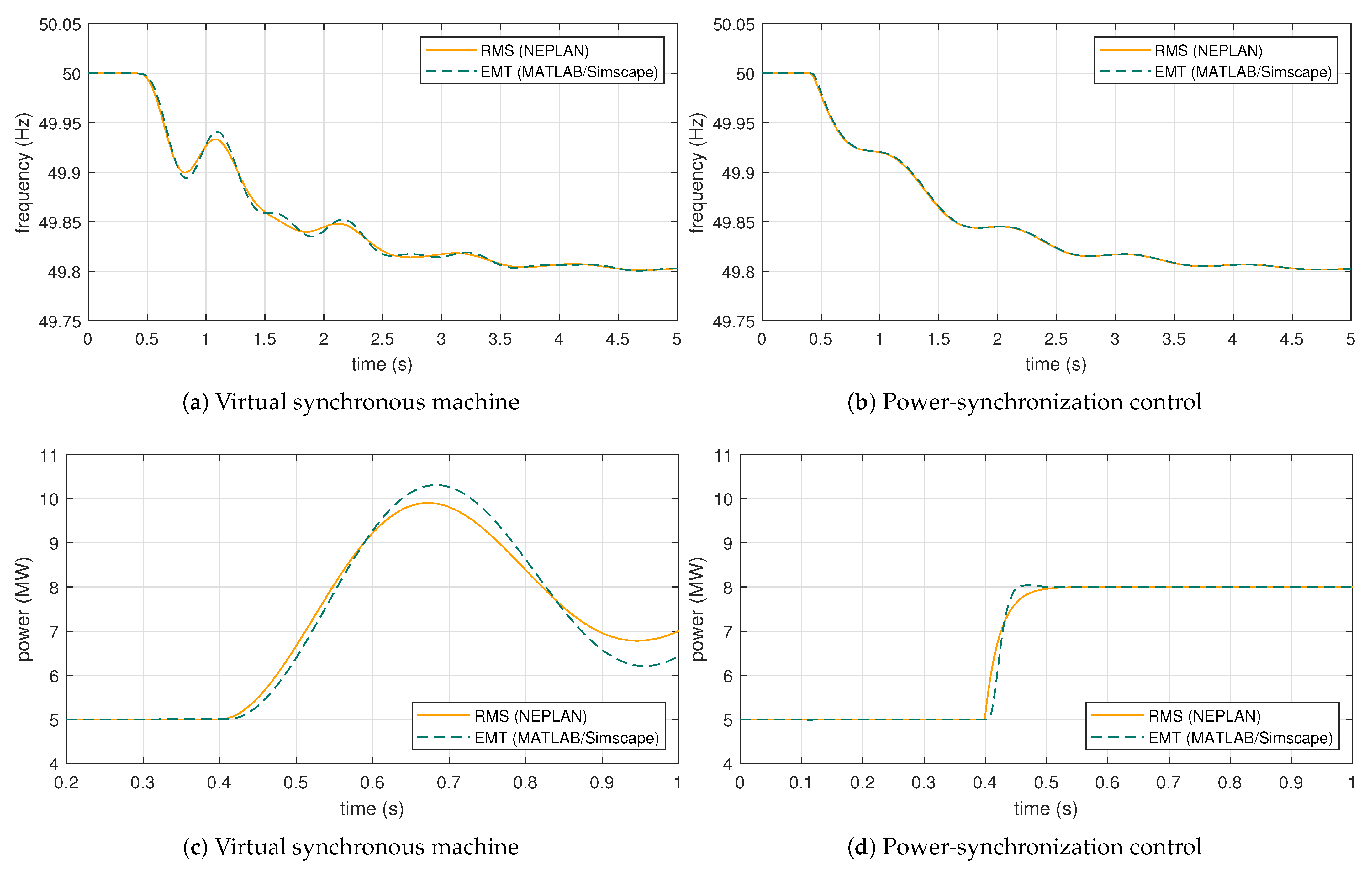
5.7. Impact of Control Strategy

The possible contribution of converter-interfaced generation sources implementing grid-supporting controls is investigated considering two critical cases identified in the previous analyses. As observed, the realization of the inertial effect in grid-forming controls through an internal synthetic oscillator can significantly affect the power–frequency dynamics of an autonomous system. If the inertial effect is reduced, the control action of the grid-forming converters becomes faster and all the oscillating units can rapidly reach a successful synchronization between each other. Implementing inertia-less grid-forming schemes such as droop-based controls, the frequency dynamics of the system would be clearly stabilized. However, a given amount of inertia might still be required. A possible alternative for the realization of the inertial effect would be to call the other grid-following units to participate in the power–frequency dynamics of the system. This category of converters control can in fact realize the synthetic inertia in different ways, i.e., emulating the principle of synchronous machines through derivative-based methods on the frequency acquired by the phase-locked loop, but in any case without the need for including a grid-independent internal oscillator in the control. This possibility is here investigated for two different system configurations.
In the first configuration, the system includes only two grid-forming units, with relatively small rated powers and connected at close locations in the network. The two units have a rated power of S r = 2 MVA each, and they are connected at close locations to the same feeder (A-01 and A-05 in Figure 7). As seen, small rated powers and short electrical distances can have a critical impact on the frequency dynamics of the system. In contrast to the previous simulation cases, the grid-following units are assumed this time to be capable of supporting the grid with specific frequency services. For that, they implement a derivative-based control to synthetically provide an inertial effect in the dynamic response. The analysis is performed for different values of the inertia provided by the grid-supporting units. The simulation results are shown in Figure 13. It can be immediately observed that the exclusion of the inertial action from the grid-forming controls has a positive effect on the power–frequency dynamics of the system, allowing a successful synchronization between the oscillating grid-forming units. The provision of inertial effect by the grid-supporting units does not undermine the oscillatory stability of the system, but it rather contributes positively to obtain the required performance in the frequency dynamics.
In the second configuration, many small grid-forming units are distributed across the system, amounting to the 30% of the total required generation. As seen, a high number of grid-forming with small rated powers is a critical condition for the frequency dynamics of the system. The system includes only one grid-forming unit relatively bigger than the other, connected to guarantee an appropriate primary reserve. The small units have a rated power of S r = 100 kVA each. Similarly to the previous case, the interfaced generation sources implement a grid-supporting control scheme, with the capability of providing synthetic inertia to the system. The analysis is performed for different values of the inertia provided by the grid-supporting units. Even if this configuration is less likely than the first one, it is reported in the analysis for the sake of completeness. The simulation results are shown in Figure 14. The results basically confirm the opportunity of including inertia-less grid-forming units in the system. In this case, the grid-forming units are assigned the task of realizing an effective synchronization process through fast control actions. The task of providing the required inertial effect is left instead to the grid-supporting units, ensuring a stable frequency dynamics of the system.

6. Conclusions

The power–frequency dynamics of autonomous systems with 100% converter-interfaced generation has been analyzed, starting from a theoretical point of view and then examining the existing electrical network of Pantelleria island as a case study. For a fully non-synchronous operation of the system, basic design principles for the determination of the required amount of grid-forming power are proposed and applied to the case study. The considerations obtained from the investigations and the possible solutions for a fully non-synchronous operation of autonomous systems can be summarized as follows. The selection of a few big units with grid-forming capabilities appears to be generally preferable. The few selected grid-forming must be ideally reliable sources with relatively high rated powers, such as storage systems or large wind power plants. Small grid-forming converters might not be able to effectively synchronize with each other, since they would not be strong enough to impose the frequency at their terminals. Many small grid-forming units distributed across the system might introduce sustained oscillations and experience critical issues in the synchronization process, competing for synchronism with each other and in the worst cases leading to the instability of the system. For the units implementing the grid-forming control, electrical distances and relative locations in the grid, fast control actions and the reduction of the inertial effect are all recognized as essential aspects for securing the synchronization and the stability of the system. For a good system design, grid-forming units should implement fast control actions with small inertial time constants, while the required inertial effect could be provided by grid-following units participating in the frequency control.
It is finally worth underlying the importance of this kind of study from the perspective of a full and effective integration of renewable energy sources on small islands. Indeed, studies in the literature are mainly focused on energy aspects or steady-state issues (power losses, voltage regulation, etc.) related to the integration of renewable energy sources in isolated systems, and only a few authors discuss the dynamic issues of fully non-synchronous autonomous networks. The proposed study aims to address some of the research gaps discussed in the introduction, and it demonstrates that much effort must still be made in the definition of an effective way to size and design autonomous systems dominated by converter-interfaced generation, while preserving their stability and security of supply.

Author Contributions

Conceptualization, methodology, collection and processing of data, R.M. and G.Z.; Model development and simulations, R.M.; Writing—original draft, R.M.; Writing—review and editing, G.Z.; Supervision, M.G.I. and E.R.S. All authors have read and agreed to the published version of the manuscript.

Funding

This research received no external funding.

Conflicts of Interest

The authors declare no conflict of interest.

References

  1. Ackermann, T.; Prevost, T.; Vittal, V.; Roscoe, A.J.; Matevosyan, J.; Miller, N. Paving the Way: A Future without Inertia Is Closer Than You Think. IEEE Power Energy Mag. 2017, 15, 61–69. [Google Scholar] [CrossRef] [Green Version]
  2. Matevosyan, J.; Badrzadeh, B.; Prevost, T.; Quitmann, E.; Ramasubramanian, D.; Urdal, H.; Huang, S.; Vital, V.; O’Sullivan, J.; Quint, R. Grid-Forming Inverters: Are They the Key for High Renewable Penetration? IEEE Power Energy Mag. 2019, 17, 89–98. [Google Scholar] [CrossRef]
  3. Ramasubramanian, D.; Farantatos, E.; Ziaeinejad, S.; Mehrizi-Sani, A. Operation paradigm of an all converter interfaced generation bulk power system. IET Gener. Transm. Distrib. 2018, 12, 4240–4248. [Google Scholar] [CrossRef]
  4. Ndreko, M.; Rüberg, S.; Winter, W. Grid forming control scheme for power systems with up to 100% power electronic interfaced generation: A case study on Great Britain test system. IET Renew. Power Gener. 2020, 14, 1268–1281. [Google Scholar] [CrossRef]
  5. Chen, J.; Liu, M.; Milano, F.; O’Donnell, T. 100% Converter-Interfaced generation using virtual synchronous generator control: A case study based on the irish system. Electr. Power Syst. Res. 2020, 187, 106475. [Google Scholar] [CrossRef]
  6. Kouzelis, K.; Musca, R. A Study of Power-Frequency Dynamics in Isolated Power Networks with 100% Converter-Interfaced Generation. In Proceedings of the 19th Wind Integration Workshop, Virtual Conference, 11–12 November 2020. [Google Scholar]
  7. Gouveia, J.; Moreira, C.L.; Peças Lopes, J.A. Influence of Load Dynamics on Converter-Dominated Isolated Power Systems. Appl. Sci. 2021, 11, 2341. [Google Scholar] [CrossRef]
  8. Gouveia, J.; Moreira, C.L.; Peças Lopes, J.A. Grid-Forming Inverters Sizing in Islanded Power Systems—A stability perspective. In Proceedings of the 2019 International Conference on Smart Energy Systems and Technologies (SEST), Porto, Portugal, 9–11 September 2019. [Google Scholar]
  9. Bongiorno, M.; Favuzza, S.; Ippolito, M.G.; Musca, R.; Navia, M.S.N.; Sanseverino, E.R.; Zizzo, G. An Analysis of the Intertial Response of Small Isolated Power Systems in Presence of Generation from Renewable Energy Sources. In Proceedings of the IEEE 4th International Forum on Research and Technologies for Society and Industry, Palermo, Italy, 10–13 September 2018. [Google Scholar]
  10. Delille, G.; François, B.; Malarange, G. Dynamic Frequency Control Support by Energy Storage to Reduce the Impact of Wind and Solar Generation on Isolated Power System’s Inertia. IEEE Trans. Sustain. Energy 2012, 3, 931–939. [Google Scholar] [CrossRef]
  11. Horne, J.; Flynn, D.; Littler, T. Frequency Stability Issues for Islanded Power Systems. In Proceedings of the IEEE PES Power Systems Conference and Exposition, New York, NY, USA, 10–13 October 2004. [Google Scholar]
  12. Yuan, C.; Xie, P.; Yang, D.; Xiao, X. Transient Stability Analysis of Islanded AC Microgrids with a Significant Share of Virtual Synchronous Generators. Energies 2018, 11, 44. [Google Scholar] [CrossRef] [Green Version]
  13. Bongiorno, M.; Favuzza, S.; Ippolito, M.G.; Musca, R.; Navia, M.S.N.; Sanseverino, E.R.; Zizzo, G. System Stability of a Small Island’s Network with Different Levels of Wind Power Penetration. In Proceedings of the IEEE 4th International Forum on Research and Technologies for Society and Industry, Palermo, Italy, 10–13 September 2018. [Google Scholar]
  14. Eskandari, M.; Li, L.; Moradi, M.; Siano, P. A nodal approach based state-space model of droop-based autonomous networked microgrids. Sustain. Energy Grids Netw. 2019, 18, 100216. [Google Scholar] [CrossRef]
  15. Krismanto, A.; Mithulananthan, N.; Krause, O. Stability of Renewable Energy based Microgrid in Autonomous Operation. Sustain. Energy Grids Netw. 2018, 13, 134–147. [Google Scholar] [CrossRef] [Green Version]
  16. Oureilidis, K.O.; Demoulias, C. A decentralized impedance-based adaptive droop method for power loss reduction in a converter-dominated islanded microgrid. Sustain. Energy Grids Netw. 2016, 5, 39–49. [Google Scholar] [CrossRef]
  17. Unruh, P.; Nuschke, M.; Strauß, P.; Welck, F. Overview on Grid-Forming Inverter Control Methods. Energies 2020, 13, 2589. [Google Scholar] [CrossRef]
  18. Weise, B.; Korai, A.; Constantin, A. Comparison of Selected Grid-Forming Converter Control Strategies for Use in Power Electronic Dominated Power Systems. In Proceedings of the 18th Wind Integration Workshop, Dublin, Ireland, 16–18 October 2019. [Google Scholar]
  19. Zhong, Q.C.; Weiss, G. Synchronverters: Inverters that mimic synchronous generators. IEEE Trans. Ind. Electron. 2011, 58, 1259–1267. [Google Scholar] [CrossRef]
  20. Roscoe, A.J.; Yu, M.; Dyśko, A.; Booth, C.; Ierna, R.; Zhu, J.; Urdal, H. A VSM (Virtual Synchronous Machine) Convertor Control Model Suitable for RMS Studies for Resolving System Operator Owner Challenges. In Proceedings of the 15th Wind Integration Workshop, Vienna, Austria, 15–17 November 2016. [Google Scholar]
  21. Zhang, L.; Harnefors, L.; Nee, H.P. Power-Synchronization Control of Grid-Connected Voltage-Source Converters. IEEE Trans. Power Syst. 2010, 25, 809–820. [Google Scholar] [CrossRef]
  22. Rocabert, J.; Luna, A.; Blaabjerg, F.; Rodriguez, P. Control of Power Converters in AC Microgrids. IEEE Trans. Power Electron. 2012, 27, 4734–4749. [Google Scholar] [CrossRef]
  23. Tayyebi, A.; Groß, D.; Anta, A.; Kupzog, F.; Dörfler, F. Interactions of Grid-Forming Power Converters and Synchronous Machines—A Comparative Study. arXiv 2019, arXiv:1902.10750. [Google Scholar]
  24. Zuo, Y.; Yuan, Z.; Sossan, F.; Zecchino, A.; Cherkaoui, R.; Paolone, M. Performance assessment of grid-forming and grid-following converter-interfaced battery energy storage systems on frequency regulation in low-inertia power grids. Sustain. Energy Grids Netw. 2021, 27, 100496. [Google Scholar] [CrossRef]
  25. Bevrani, H.; Ise, T.; Miura, Y. Virtual synchronous generators: A survey and new perspectives. Electr. Power Syst. Res. 2014, 54, 244–254. [Google Scholar] [CrossRef]
  26. Mohammed, O.O.; Otuoze, A.O.; Salisu, S.; Ibrahim, O.; Rufa’i, N.A. Virtual Synchronous Generator: An Overview. Niger. J. Technol. 2019, 38, 153–164. [Google Scholar] [CrossRef]
  27. D’Arco, S.; Suul, J.A.; Fosso, O.B. A Virtual Synchronous Machine implementation for distributed control of power converters in SmartGrids. Electr. Power Syst. Res. 2015, 122, 180–197. [Google Scholar] [CrossRef]
  28. Yu, M.; Roscoe, A.J.; Booth, C.D.; Dysko, A.; Ierna, R.; Zhu, J.; Urdal, H. Use of an Inertia-less Virtual Synchronous Machine within Future Power Networks with High Penetrations of Converters. In Proceedings of the 2016 Power Systems Computation Conference (PSCC), Genoa, Italy, 20–24 June 2016. [Google Scholar]
  29. Hesse, R.; Turschner, D.; Beck, H.P. Micro grid stabilization using the Virtual Synchronous Machine (VISMA). In Proceedings of the International Conference on Renewable Energies and Power, Valencia, Spain, 15–17 April 2009. [Google Scholar]
  30. Pogaku, N.; Prodanovic, M.; Green, T.C. Modeling, Analysis and Testing of Autonomous Operation of an Inverter-Based Microgrid. IEEE Trans. Power Electron. 2007, 22, 613–625. [Google Scholar] [CrossRef] [Green Version]
  31. Brabandere, K.D.; Bolsens, B.; den Keybus, J.V.; Woyte, A.; Driesen, J.; Balmans, R. A voltage and frequency droop control method for parallel inverters. IEEE Trans. Power Electron. 2007, 22, 1107–1115. [Google Scholar] [CrossRef]
  32. Khaledia, A.; Golkar, M.A. Analysis of droop control method in an autonomous microgrid. J. Appl. Res. Technol. 2017, 15, 371–377. [Google Scholar] [CrossRef]
  33. NEPLAN Power Systems Analysis Software. Available online: https://www.neplan.ch/en-products/ (accessed on 2 February 2022).
  34. MATLAB Scientific Computation Software. Available online: https://mathworks.com/products/matlab.html (accessed on 2 February 2022).
  35. Dörfler, F.; Bullo, F. Synchronization in complex networks of phase oscillators: A survey. Automatica 2014, 50, 1539–1564. [Google Scholar] [CrossRef] [Green Version]
  36. Pan, D.; Wang, X.; Liu, F.; Shi, R. Transient Stability of Voltage-Source Converters With Grid-Forming Control: A Design-Oriented Study. IEEE J. Emerg. Sel. Top. Power Electron. 2020, 8, 1019–1033. [Google Scholar] [CrossRef]
  37. Liu, J.; Miura, Y.; Ise, T. Comparison of Dynamic Characteristics between Virtual Synchronous Generator and Droop Control in Inverter-Based Distributed Generators. IEEE Trans. Power Electron. 2016, 31, 3600–3611. [Google Scholar] [CrossRef]
  38. Pan, R.; Sun, P. Extra transient block for virtual synchronous machine with better performance. IET Gener. Transm. Distrib. 2020, 14, 1186–1196. [Google Scholar] [CrossRef]
  39. Qoria, T.; Gruson, F.; Colas, F.; Denis, G.; Prevost, T.; Guillaud, X. Inertia Effect and Load Sharing Capability of Grid Forming Converters Connected to a Transmission Grid. In Proceedings of the 15th IET International Conference on AC and DC Power Transmission, Coventry, UK, 5–7 February 2019. [Google Scholar]
  40. Kundur, P.; Balu, N.J.; Lauby, M.G. Power System Stability and Control; McGraw-Hill: New York, NY, USA, 1994. [Google Scholar]
  41. Harnefors, L.; Hinkkanen, M.; Riaz, U.; Rahman, F.M.M.; Zhang, L. Robust Analytic Design of Power-Synchronization Control. IEEE Trans. Ind. Electron. 2019, 66, 5810–5819. [Google Scholar] [CrossRef] [Green Version]
  42. High Penetration of Power Electronic Interfaced Power Sources and the Potential Contribution of Grid Forming Converters; ENTSO-E Technical Report; ENTSO-E: Brussels, Belgium, January 2020.
  43. Liu, J.; Miura, Y.; Ise, T. A Comparative Study on Damping Methods of Virtual Synchronous Generator Control. In Proceedings of the 21st European Conference on Power Electronics and Applications (EPE19), Genova, Italy, 2–6 September 2019. [Google Scholar]
  44. Gao, B.; Xia, C.; Chen, N.; Cheema, K.M.; Yang, L.; Li, C. Virtual Synchronous Generator Based Auxiliary Damping Control Design for the Power System with Renewable Generation. Energies 2017, 10, 1146. [Google Scholar] [CrossRef]
  45. Pipelzadeh, Y.; Chaudhuri, B.; Green, T.C. Control Coordination Within a VSC HVDC Link for Power Oscillation Damping: A Robust Decentralized Approach Using Homotopy. IEEE Trans. Control Syst. Technol. 2013, 21, 1270–1279. [Google Scholar] [CrossRef] [Green Version]
  46. Ndreko, M.; van der Meer, A.A.; Rawn, B.G.; Gibescu, M.; van der Meijden, M.A.M.M. Damping Power System Oscillations by VSC-Based HVDC Networks: A North Sea Grid Case Study. In Proceedings of the International Workshop on Large-Scale Integration of Wind Power into Power Systems as well as on Transmission Networks for Offshore Wind Power Plants, London, UK, 22–24 October 2013. [Google Scholar]
  47. Dong, S.; Chen, Y.C. Adjusting Synchronverter Dynamic Response Speed via Damping Correction Loop. IEEE Trans. Energy Convers. 2017, 32, 608–619. [Google Scholar] [CrossRef]
  48. Ebrahimi, M.; Khajehoddin, S.A.; Karimi-Ghartemani, M. An Improved Damping Method for Virtual Synchronous Machines. IEEE Trans. Sustain. Energy 2019, 10, 1491–1500. [Google Scholar] [CrossRef]
  49. Bongiorno, M.; Ippolito, M.G.; Musca, R.; Zizzo, G. Damping Provision by Different Virtual Synchronous Machine Schemes. In Proceedings of the 20th International Conference on Environment and Electrical Engineering and 4th Industrial and Commercial Power Systems Europe (EEEIC/I&CPS Europe), Madrid, Spain, 9–12 June 2020. [Google Scholar]
  50. Bongiorno, M.; Musca, R.; Zizzo, G. Grid Forming Converters in Weak Grids: The Case of a Mediterranean Island. In Proceedings of the 18th Wind Integration Workshop, Dublin, Ireland, 16–18 October 2019. [Google Scholar]
  51. Huang, L.; Xin, H.; Wang, Z. Damping Low-Frequency Oscillations Through VSC-HVDC Stations Operated as Virtual Synchronous Machines. IEEE Trans. Power Electron. 2019, 34, 5803–5818. [Google Scholar] [CrossRef]
  52. Bao, F.; Guo, J.; Wang, W.; Wang, B. Cooperative Control Strategy of Multiple VSGs in Microgrid Based on Adjacent Information. IEEE Access 2021, 9, 125603–125615. [Google Scholar] [CrossRef]
  53. Zhang, L.; Zheng, H.; Wan, T.; Shi, D.; Lyu, L.; Cai, G. An integrated control algorithm of power distribution for islanded microgrid based on improved virtual synchronous generator. IET Renew. Power Gener. 2021, 15, 2674–2685. [Google Scholar] [CrossRef]
  54. Liu, X.; Gong, R. A control strategy of microgrid-connected system based on VSG. In Proceedings of the 2020 IEEE International Conference on Power, Intelligent Computing and Systems (ICPICS), Shenyang, China, 28–30 July 2020. [Google Scholar] [CrossRef]
  55. Kim, J.Y.; Jeon, J.H.; Kim, S.K.; Cho, C.; Park, J.H.; Kim, H.M.; Nam, K.Y. Cooperative control strategy of energy storage system and microsources for stabilizing the microgrid during islanded operation. IEEE Trans. Power Electron. 2010, 25, 3037–3048. [Google Scholar] [CrossRef]
  56. Choopani, M.; Hosseinian, S.H.; Vahidi, B. New transient stability and LVRT improvement of multi-VSG grids using the frequency of the center of inertia. IEEE Trans. Power Syst. 2020, 35, 527–538. [Google Scholar] [CrossRef]
  57. Choopani, M.; Hosseinain, S.H.; Vahidi, B. A novel comprehensive method to enhance stability of multi-VSG grids. Int. J. Electr. Power Energy Syst. 2019, 104, 502–514. [Google Scholar] [CrossRef]
  58. Zhenao, S.; Fanglin, Z.; Xingchen, C. Study on a Frequency Fluctuation Attenuation Method for the Parallel Multi-VSG System. Front. Energy Res. 2021, 9, 310. [Google Scholar] [CrossRef]
  59. Du, W.; Chen, Z.; Schneider, K.P.; Lasseter, R.H.; Nandanoori, S.P.; Tuffner, F.K.; Kundu, S. A Comparative Study of Two Widely Used Grid-Forming Droop Controls on Microgrid Small-Signal Stability. IEEE J. Emerg. Sel. Top. Power Electron. 2020, 8, 963–975. [Google Scholar] [CrossRef]
  60. Chen, M.; Zhou, D.; Blaabjerg, F. Active Power Oscillation Damping Based on Acceleration Control in Paralleled Virtual Synchronous Generators System. IEEE Trans. Power Electron. 2021, 36, 9501–9510. [Google Scholar] [CrossRef]
  61. Guo, J.; Chen, Y.; Liao, S.; Wu, W.; Zhou, L.; Xie, Z.; Wang, X. Analysis and Mitigation of Low-Frequency Interactions Between the Source and Load Virtual Synchronous Machine in an Islanded Microgrid. IEEE Trans. Ind. Electron. 2021, 69, 3732–3742. [Google Scholar] [CrossRef]
  62. Beires, P.P.; Moreira, C.L.; Peças Lopes, J.A. Grid-forming inverters replacing Diesel generators in small-scale islanded power systems. In Proceedings of the 2019 IEEE Milan PowerTech, Milan, Italy, 23–27 June 2019. [Google Scholar]
  63. Fang, J.; Li, H.; Tang, Y.; Blaabjerg, F. Distributed Power System Virtual Inertia Implemented by Grid-Connected Power Converters. IEEE Trans. Power Electron. 2018, 33, 8488–8499. [Google Scholar] [CrossRef] [Green Version]
  64. MIGRATE Deliverable D1.1. Report on Systemic Issues. December 2016. Available online: https://ec.europa.eu/research/participants/documents/downloadPublic?documentIds=080166e5af08ecd7&appId=PPGMS (accessed on 2 February 2022).
  65. Poolla, B.K.; Groß, D.; Dörfler, F. Placement and Implementation of Grid-Forming and Grid-Following Virtual Inertia and Fast Frequency Response. IEEE Trans. Power Syst. 2019, 34, 3035–3046. [Google Scholar] [CrossRef] [Green Version]
  66. D’Arco, S.; Suul, J. Equivalence of Virtual Synchronous Machines and Frequency-Droops for Converter-Based MicroGrids. IEEE Trans. Smart Grid 2014, 5, 394–395. [Google Scholar] [CrossRef]
  67. Rodríguez-Cabero, A.; Roldán-Pérez, J.; Prodanovic, M. Virtual Impedance Design Considerations for Virtual Synchronous Machines in Weak Grids. IEEE J. Emerg. Sel. Top. Power Electron. 2020, 8, 1477–1489. [Google Scholar] [CrossRef]
  68. Suul, J.A.; D’Arco, S.; Rodriguez, P.; Molinas, M. Extended stability range of weak grids with Voltage Source Converters through impedance-conditioned grid synchronization. In Proceedings of the 11th IET International Conference on AC and DC Power Transmission, Birmingham, UK, 10–12 February 2015. [Google Scholar]
  69. Wang, X.; Taul, M.G.; Wu, H.; Liao, Y.; Blaabjerg, F.; Harnefors, L. Grid-Synchronization Stability of Converter-Based Resources—An Overview. IEEE Open J. Ind. Appl. 2020, 1, 115–134. [Google Scholar] [CrossRef]
Figure 1. Block diagram of the grid-forming control.
Energies 15 02220 g001
Figure 2. Detail of the angle control block: (a) Virtual synchronous machine; (b) Power-synchronization control.
Energies 15 02220 g002
Figure 3. Comparison and validation of grid-forming simulation models: (a,b) frequency transients caused by the application of a power imbalance; (c,d) step in the active power reference of the grid-forming controls.
Energies 15 02220 g003
Figure 4. Autonomous systems with multiple grid-forming units: (a) Outline of a generic multiple oscillators electric system; (b) Pair of coupled oscillators belonging to the multiple oscillators system.
Energies 15 02220 g004
Figure 5. Plot of system eigenvalues for different parametric sweeps: starting from stars, ending to squares. (a) Inertia Hc (0.01–10 s); (b) Droop Rc (0.01–0.1 pu); (c) Converter rated power Sc (0.1–10 MVA); (d) Measurement time constant Tpf (0–0.05 s); (e) Impedance magnitude (0.1–10 pu); (f) Impedance angle (0–90 degrees).
Energies 15 02220 g005
Figure 6. Small-signal block diagram for the study of a single oscillator dynamics.
Energies 15 02220 g006
Figure 7. Current network scheme of Pantelleria island, with selected nodes in the 4 feeders.
Energies 15 02220 g007
Figure 8. Impact of size of grid-forming units.
Energies 15 02220 g008
Figure 9. Impact of number of grid-forming units.
Energies 15 02220 g009
Figure 10. Impact of location of grid-forming units.
Energies 15 02220 g010
Figure 11. Impact of inertial effect in grid-forming converters.
Energies 15 02220 g011
Figure 12. Impact of virtual impedance in grid-forming converters.
Energies 15 02220 g012
Figure 13. Contribution of grid-supporting controls with two grid-forming converters.
Energies 15 02220 g013
Figure 14. Contribution of grid-supporting controls with many grid-forming converters.
Energies 15 02220 g014
Table 1. Investigation factors with critical impact.
Key FactorDescription
Number and sizeShare of grid-forming converters and rated powers
LocationElectrical distances and impedances
Control parametersInertial effect and virtual impedance
Table 2. Impact of rated powers and inertial effect.
Sr (MVA)System Response
GFM1GFM2H1 = H2H1 ≪ H2H1 ≫ H2
11unstablemarginally stablemarginally stable
44stablestablestable
14unstablemarginally stablestable
41unstablestablemarginally stable
Publisher’s Note: MDPI stays neutral with regard to jurisdictional claims in published maps and institutional affiliations.

