Article

Active Power Control to Mitigate Frequency Deviations in Large-Scale Grid-Connected PV System Using Grid-Forming Single-Stage Inverters

by
Ali Q. Al-Shetwi
1,
Walid K. Issa
1,
Raed F. Aqeil
1,
Taha Selim Ustun
2,*,
Hussein M. K. Al-Masri
3,
Khaled Alzaareer
4,
Maher G. M. Abdolrasol
5 and
Majid A. Abdullah
6
1
Electrical Engineering Department, Fahad Bin Sultan University, Tabuk 47721, Saudi Arabia
2
Fukushima Renewable Energy Institute, AIST (FREA), National Institute of Advanced Industrial Science and Technology (AIST), Koriyama 963-0298, Japan
3
Department of Electrical Power Engineering, Yarmouk University, Irbid 21163, Jordan
4
Electrical Engineering Department, Faculty of Engineering, Philadelphia University, Amman 19392, Jordan
5
Department of Electrical Engineering, Universiti Kebangsaan Malaysia, Bangi 43600, Malaysia
6
Department of Electrical and Electronics Engineering, Community College, University of Hafr Al Batin, Hafr Al-Batin 31991, Saudi Arabia
*
Author to whom correspondence should be addressed.
Energies 2022, 15(6), 2035; https://doi.org/10.3390/en15062035
Submission received: 4 February 2022 / Revised: 5 March 2022 / Accepted: 7 March 2022 / Published: 10 March 2022
(This article belongs to the Collection Young Researchers in Electrical Power and Energy System)

Abstract

:
Over the last few years, the number of grid-connected photovoltaic systems (GCPVS) has expanded substantially. The increase in GCPVS integration may lead to operational issues for the grid. Thus, modern GCPVS control mechanisms should be used to improve grid efficiency, reliability, and stability. In terms of frequency stability, conventional generating units usually have a governor control that regulates the primary load frequency in cases of imbalance situations. This control should be activated immediately to avoid a significant frequency variation. Recently, renewable distribution generators such as PV power plants (PVPPs) are steadily replacing conventional generators. However, these generators do not contribute to system inertia or frequency stability. This paper proposes a control strategy for a GCPVS with active power control (APC) to support the grid and frequency stability. The APC enables the PVPP to withstand grid disturbances and maintain frequency within a normal range. As a result, PVPP is forced to behave similar to traditional power plants to achieve frequency steadiness stability. Frequency stability can be achieved by reducing the active power output fed into the grid as the frequency increases. Additionally, to maintain power balance on both sides of the inverter, the PV system will produce the maximum amount of active power achievable based on the frequency deviation and the grid inverter’s rating by working in two modes: normal and APC (disturbance). In this study, a large-scale PVPP linked to the utility grid at the MV level was modeled in MATLAB/Simulink with a nominal rated peak output of 2000 kW. Analyses of the suggested PVPP’s dynamic response under various frequency disturbances were performed. In this context, the developed control reduced active power by 4%, 24%, and 44% when the frequency climbed to 50.3 Hz, 50.8 Hz, and 51.3 Hz, respectively, and so stabilized the frequency in the normal range, according to grid-code requirements. However, if the frequency exceeds 51.5 Hz or falls below 47.5 Hz, the PVPP disconnects from the grid for safety reasons. Additionally, the APC forced the PVPP to feed the grid with its full capacity generated (2000 kW) at normal frequency. In sum, the large-scale PVPP is connected to the electrical grid provided with APC capability has been built. The system’s capability to safely ride through frequency deviations during grid disturbances and resume initial conditions was achieved and improved. The simulation results show that the given APC is effective, dependable, and suitable for deployment in GCPVS.

1. Introduction

Solar photovoltaic (PV) demand is spreading and developing as it becomes the most cost-effective choice for energy generation in many areas, such as home-energy systems, off-grid microgrids or utility-scale projects [1,2,3]. Since 2013, power generated by PV has been the highest among renewable sources [4]. The generation of electricity from solar energy has witnessed a significant increase, with new installations totaling an estimated 130 GW by the end of 2020. In this regard, penetration of PV power plants (PVPPs) into electrical power systems has been increased dramatically, as shown in Figure 1 [5]. Because of the high integration levels of PV systems into the electrical grid, new rules have been put in place for power system operators and some grid codes (GCs) that should be met [6]. The new integration requirements stipulate PVPPs to act similar to traditional power plants and play a key role in improving frequency and voltage stability, withstanding diverse disturbances, and enhancing the utility grid stability, reliability, security, and power quality [7]. For instance, during grid faults, new GCs need PVPPs to withstand the fault and support the voltage stability using reactive power injection, as in the case of conventional power generators [8], and the research shows that PVPPs are not capable of doing that under certain conditions, e.g., fault conditions or frequency swings may cause inverters to disconnect or cease generation momentarily [9].
For grid frequency stability, the generation capacity should be equivalent to the required load; otherwise, frequency problems may occur and thus lead to service disconnection [10]. Conventional generators (such as steam, diesel and gas), which are generally equipped with a governor control, can stabilize the deviation in grid frequency (50 or 60 Hz) by reducing their output power through active power control [11]. Consequently, the demanding efforts to replace conventional power generators with PV systems necessitate embedding such features for stable renewable power generation.
PVPPs have a lot of qualities that are different from conventional power plants. As a result, GCPVS are faced with a slew of novel issues. Moreover, the high penetration of renewable power sources affects the operation of power systems [12]. In the past, when PVPP penetration level was low, all regulations required these plants to disconnect directly as soon as a grid fault or disturbance occurred. Nevertheless, because of the high penetration of PV systems, disconnections occurring simultaneously with grid disturbances would pose stability and operational issues and may even result in a blackout [13]. In terms of frequency stability, traditional generation units have a governor control that functions as a primary load-frequency control during frequency deviations. To avoid big deviations in the frequency, this control must be turned on right away. It will reduce the amount of active power that is injected into the grid to keep the frequency stable [14].
Recently, distribution generators such as PVPPs, which have no governor control, are gradually replacing conventional generators [15]. Thus, problems with frequency stability will arise, necessitating immediate resolution. In this regard, recent studies have confirmed that major frequency deviations and instability issues are to be expected [16,17,18]. For instance, several new GCs require frequency management capability in the future generation of PV systems to assure network stability. Frequency control can be done by reducing the amount of active power that is put into the grid when the frequency goes up. This is called “active power control” (APC). A power ramp rate limiter is also being added in various GCs, which presents a barrier for PVPP integration due to the absence of inertia in their systems [19]. To solve these issues, APC capability is becoming an essential capability of the modern power system to enforce the PVPPs to behave similar to traditional power plants and contribute towards achieving frequency stability. When the grid frequency exceeds 50.2 Hz to 51.5 Hz, PVPPs must reduce the produced active power by a factor of 40% per Hz of the supplied PV power, according to the German GC. If the grid frequency is less than 50.2 Hz, the available active power generated by PVPP should immediately increase [20,21]. The US GC requires PVPPs to govern frequency deviation by active power control in the same way as traditional generators, with a drop characteristic of 5% [22].
According to the new Malaysian regulation, PVPPs must operate continuously in the 47–50.5 Hz frequency range. However, the PVPP is projected to lower its active power by 40% per Hz if the system frequency surpasses 50.5 Hz during over-frequency events [23]. In terms of China GC, the use of an APC may not be required. However, the PVPPs must endure the over-frequency occurrence (50.2–50.5 Hz) within 2 min. Otherwise, the disconnection of PVPPs from the power grid is required [24]. Even though the capability of APC requirements for GVPVs is extremely critical for frequency stability, it is not explicitly described in various grid codes. The APC is also delegated to distribution or transmission system operators in several countries, such as South Africa [25]. Overall, the German grid code imposes the strictest restrictions in terms of ACP for PV system integration. APC is expected to become a necessity for additional countries in the near future as renewable energy deployment increases.
In the literature, numerous studies have been conducted to meet the requirements of various grid codes. For instance, the feedback linearization approach (FLS) was suggested in [26]. In this study, the inverter can ride-through grid faults by maintaining current levels within its set limits, ensuring that it is safe to operate during disturbances. A new fault-ride-through control scheme that limits fault current within the limits of the system is presented in [27]. Some other studies focused on fulfilling other requirements such as harmonics [28], voltage unbalance [29], and voltage stability [30]. These studies, however, ignored the APC capability. Although most of the above studies focused on voltage stability regarding the PV pentation of the electric grid, only a few studies investigated the frequency stability. Predictive PV inverter control, for example, has been presented in [31] for fast and precise management of active power. However, the APC was not exactly used to change according to the frequency variation.
There have been some studies focusing on the use of smart inverters and their impact on grid stability [32]. However, these are performed at distribution level for individual households and not in large-scale power plants [33]. Grid-code requirements can be met using a two-second time window ramp rate restriction for PV plants incorporating energy storage devices, as demonstrated in [19]. However, this method depends on weak battery behavior, while power oscillations could occur. Frequency synchronization of GCPVS using a frequency droop control (FDC) strategy is proposed in [34]. The FDC of PVPP showed good performance in stabilizing the frequency at the connection point. However, the ACP concept during over-frequency according to the standard requirements is not taken into consideration. In [35], active power analysis of wind farms based on the frequency domain using closed-loop control is conducted. However, only the frequency impact on the operation of the wind turbine was investigated, while this study overlooked the reduction of output power once the frequency is increased. A hierarchical control architecture for over-frequency support in large-scale PVPP is introduced in [36]. In [37], authors established a frequency control with the coordination of a fractional-order PID (FOPID) controller and electric vehicles (EVs) in interconnected smart-grid power systems to improve the frequency response under changing load conditions. The proposed control was compared to PI and PID controllers and proved that the FOPID controller has better performance. However, this study does not deal with APC to reduce the frequency increase according to the new grid-code requirements. Moreover, no renewable source is connected and feeding power into the grid for frequency stability testing. As the main purpose of APCs is to enforce renewable source to behave similar to traditional power plants, which reduce their injected power according to the frequency increase, FOPID enhances the tuning frequency response and overlocked the grid frequency stability. A comprehensive review of FO controllers is given in [38] for frequency control. None of the papers are about an APC developed for renewable energy-based generation for frequency control, i.e., the main theme of the work presented herein. In addition, a smart solar inverter enables active power curtailment, as well as volt–watt and frequency–watt management systems for mitigating voltage and frequency aberrations in a smart power grid, and is presented in [39]. However, the APC based on the recent integration standards is not taken into consideration in these studies. Moreover, the behavior of renewable sources integrated into the power sector similar to traditional power plants is overlooked, which needs further investigation. Therefore, these methods do not sufficiently deal with APC to achieve efficient and comprehensive frequency stability concerning grid-code compliance. In addition, APC-capable photovoltaic inverters have yet to be commercially manufactured, and related research on the topic is in its infancy. Thus, this paper attempts to overcome the reported drawbacks and fill the gap. In view of the problem statement and literature gap, the objectives of this research can be summarized as follows:
  • To develop a complete control method that will allow large-scale PVPPs to tolerate frequency increases by rapidly reducing the necessary active power under a variety of frequency deviation scenarios to meet the standard criteria (GCs).
  • To design power control for frequency support at the grid during frequency deviation and enforce the PVPPs to behave as traditional power plants towards smooth integration and grid stability.
  • To add a new and simple control aspect to the existing single-stage inverter controller to work at normal and abnormal conditions without additional or extra elements. The controller is aimed at mitigating the frequency deviation according to the recent integration requirements during abnormal conditions.

2. Grid-Connected PV System

For an accurate design, the overall performance and reliability of the PV system is important. Consequently, proper modeling and control design permit the development and smooth performance of APC. Figure 2 depicts the power stage of a 2000 kW single-stage PVPP that was modeled in this research by means of Matlab/Simulink. The solar PV array, maximum power point tracking (MPPT), DC-link control, the inverter with its management, the filter, and the transformer that connected to the medium-voltage (MV) side of the distribution grid were all part of a three-phase GCPVS. The PV array generates 2000 kV at STC. To obtain maximum available power, the MPPT controller based on the “Perturb and Observe” technique is used. This MPPT system automatically varies the VDC reference signal of the inverter VDC regulator to obtain a DC voltage which will extract maximum power from the PV array. The DC-link is used to link between the PV system and the inverter. The converter is modeled using a 3-level IGBT bridge PWM-controlled. The inverter choke RL and a small harmonics filter C are used to filter the harmonics generated by the IGBT bridge. The inverter controller consists of an inner and outer loop to control the current and voltage, respectively. VDC regulator is developed to determine the required Id (active current) reference for the current regulator. The current references Id and Iq (reactive current) are controlled via the current regulator. The regulator determines the required reference voltages for the inverter. In this model, the Iq reference is set to zero. A three-phase transformer is used to connect the inverter to the utility distribution system. On the MV side of the distribution grid, the proposed PVPP is connected to 11 kV bus-bar in the distribution system via the step-up transformer (0.4/33) kV. For control and analysis purposes, the control structure of the three-level voltage source inverter (VSI), including the mathematical modeling, inner and outer loops of the control and the pulse width modulation (PWM) of VSI control, are synchronized to the distribution system of the power grid via a synchronous rotating reference frame-phase locked loop (SFR-PLL) based on the (d-q) synchronous reference frame [40]. The 3-ph voltage vectors are transformed from the natural reference frame (abc) to the rotating reference frame (d-q) using Park’s transformation. Multiple current and voltage control loops were used to regulate output current and voltage from the PV inverter stage to the distribution network [41]. The following subsections describe the process of designing, scaling, and testing a PV power station that is connected to the electricity grid on a model basis.

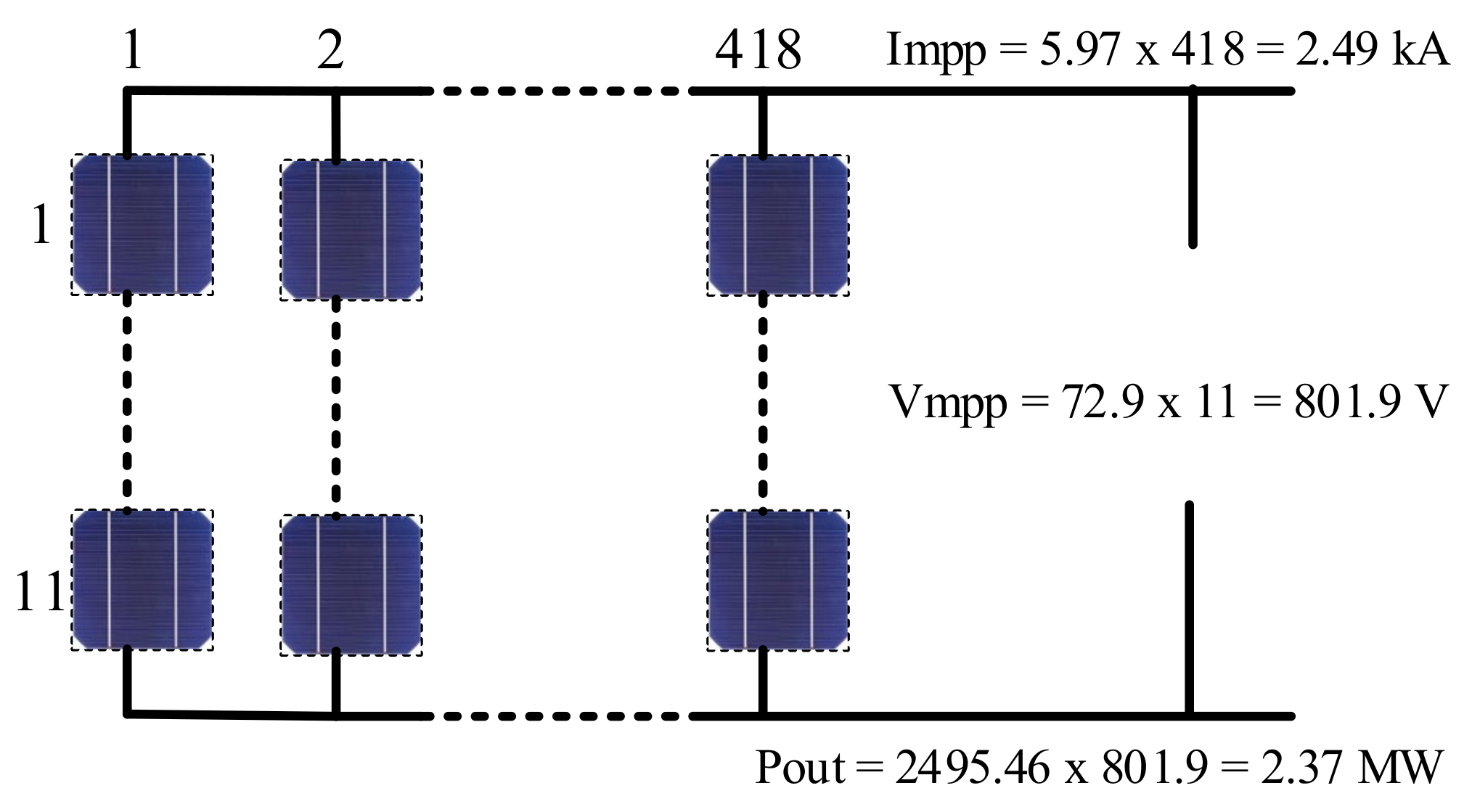
2.1. PV Array Modeling and Sizing

To study the PV system in GCPVS, modeling and analysis of the PV module of the array system are essential. The PV array is the complete power generating unit, comprising many modules linked in series and/or parallel together to yield high voltage, current, and power. In this research, a SunPower SPR-435NE-WHT-D PV Monocrystalline module has been selected for the proposed PVPP design. Every single module produces a maximum power of 435 W at standard test conditions (STC). The other electrical and mechanical specifications of the module, such as ideal factor of diode (m), short-circuit current (Isc), open-circuit voltage (Voc), maximum power current (Imp) maximum power voltage (Vmp), along with temperature coefficients of open-circuit voltage and short-circuit current (αv, αi), respectively, are provided in the datasheet by the manufacturers as listed in Table 1.
This module is used for the construction of the 2 MW PVPP. To build the proposed 2 MW PV plant, the appropriate number of PV panels could be found by dividing the maximum required power (2 MW) by maximum output power of each module. (2 × 10⁻⁶/ 435) = 4597 modules distributed as 418 parallel strings and 11 series modules [42]. Reduced output current ripple and stable voltage on the DC side of the inverter are achieved using an 800 V DC-link in this configuration [43]. In line with this, dividing the voltage of DC-link by the maximum voltage of the panel gives the number of series PV modules needed (800/72.9) = 11 series modules, and thus the parallel strings are 418 strings. Therefore, to produce 2 MW of power at STC, a 4589 unit with a maximum output of 435 W was employed and distributed as 418 parallel strings and 11 series modules, as illustrated in Figure 3. The output voltage, current, and power are 801.9 V, 2495.46 A, and 2,001,109.73 W, respectively.

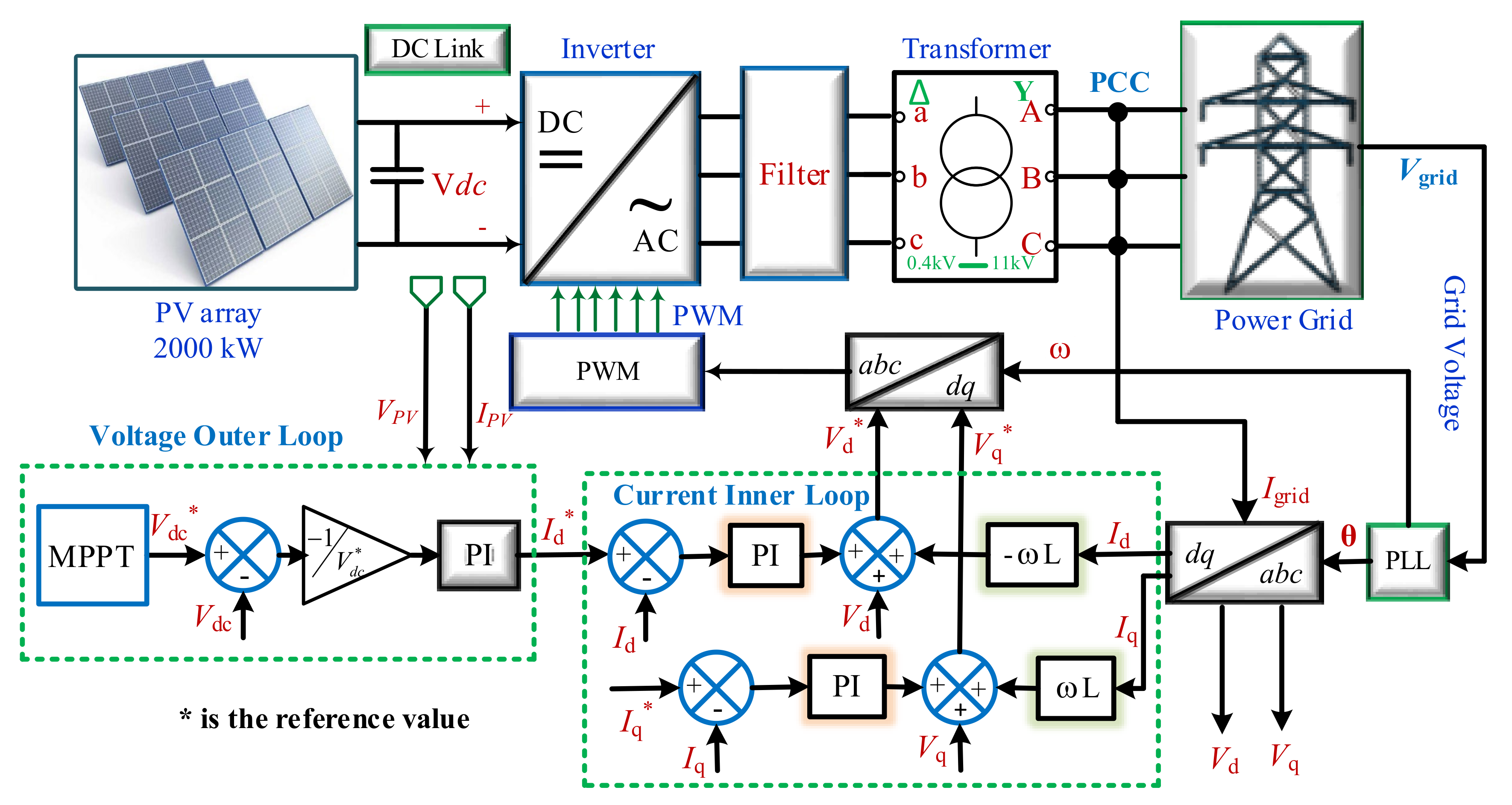
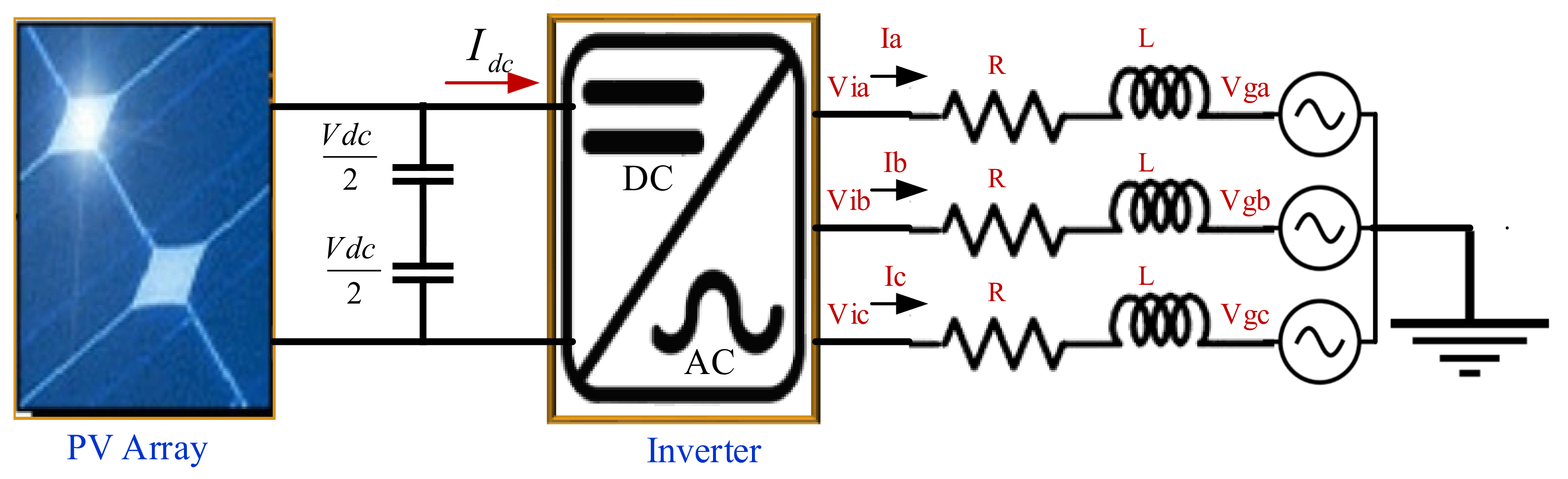
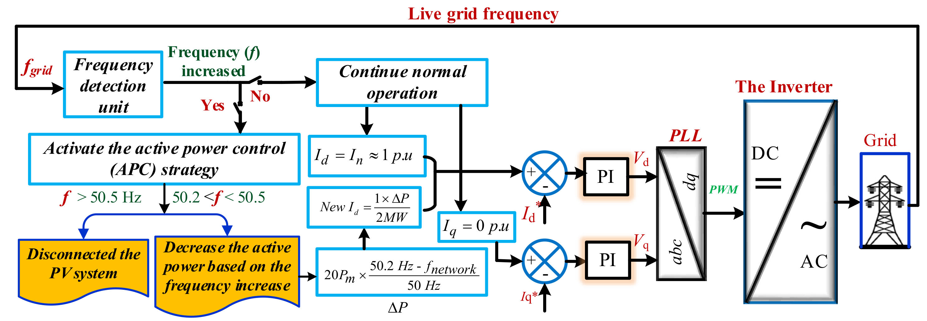
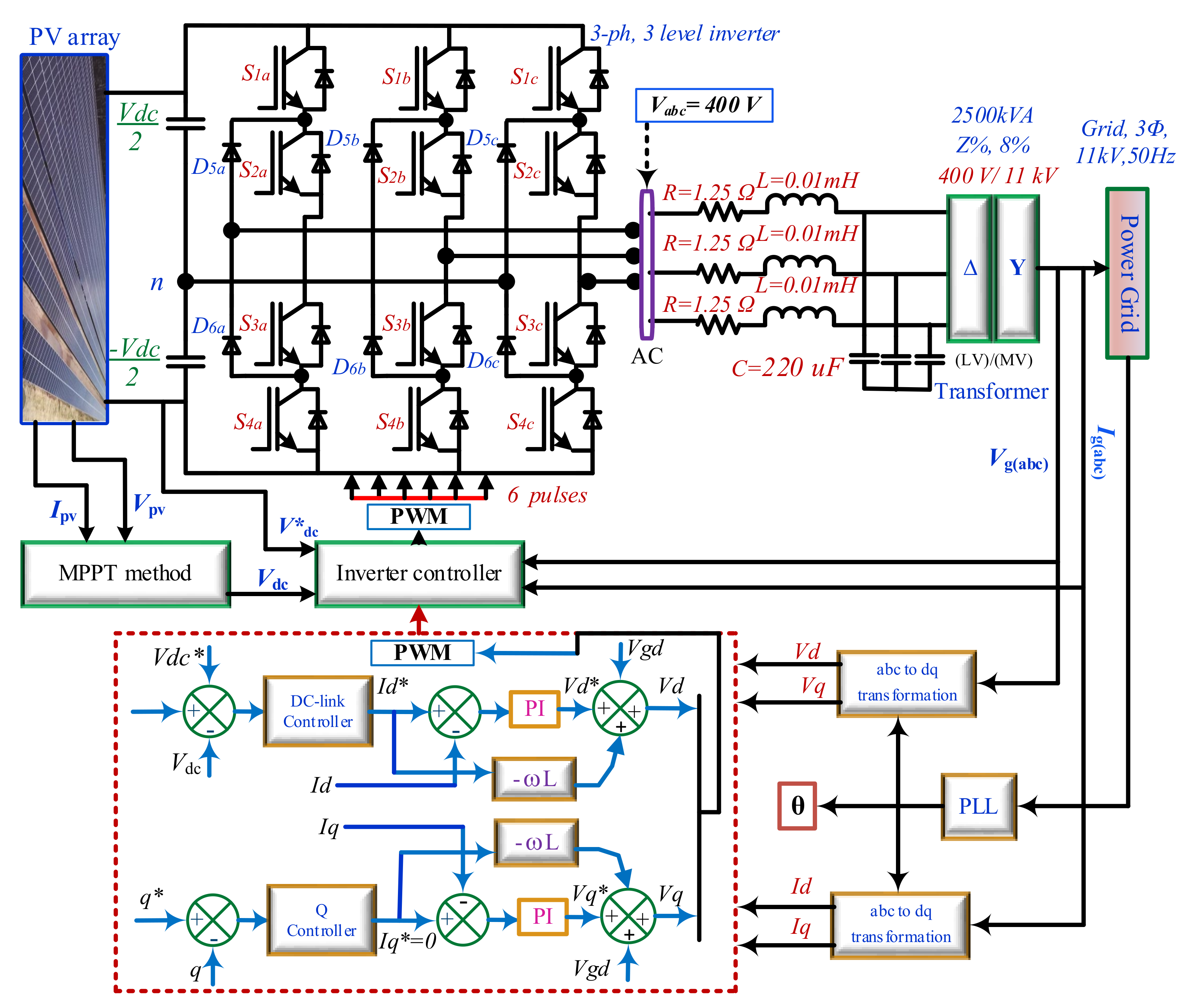
2.2. Control Strategy of PV Inverter

GCPVS (grid-connected photovoltaic system) integration into the power grid relies heavily on the inverter. There are different controllers for three inverters, such as the fractional-order proportional-integral-derivative (FOPID) controller to remove the amplitude and phase shift error while decreasing the total harmonic distortion of the current. However, the control based on PI is easier in implementation with less complexity. Control optimization and power conversion is carried out in the proposed architecture using a self-commutated VSI. The converter is represented using a PWM-controlled three-level IGBT bridge. The harmonics generated by the IGBT bridge are filtered using the inverter choke RL and a small harmonics filter C, as shown in Figure 4. Using a three-level inverter gives advantages such as producing lower output current ripple without necessarily using high switching frequency and applying lower voltage stress on inverter switches. From a system perspective, the benefits of using three-level converters are not only limited to the converter itself, but there are additional positive impacts on increased power ratings, enhanced power quality, low switching losses and reduced harmonic distortion. Thus, for a grid-connected PV system to be compatible with an MV connection, the inverter control frame must include all the basic control needs [44]. In a single-stage VSI inverter, the voltage of DC-link must be in the 550–850-volt range [45]. Therefore, the selected DC-link voltage of the system is 800 V. The selected DC-link voltage is close to the array’s maximum output voltage (796.4 V) to maintain a steady supply of voltage at the inverter’s DC side and reduce current ripple. A schematic representation of the inverter control is presented in Figure 4. Double-loop control modes are employed in this control system. It is made up of two parts: an inner current loop (which includes both reactive current (Iq) and active current (Id)) and an outer voltage loop. It is common practice to use proportional-integral (PI) controllers to regulate the DC-link voltage and grid current [46]. The typical PI controllers are used in both loops to regulate the grid current and the DC-link voltage. For easier control of active and reactive current parameters, the feed-forward decoupling strategy is applied.
The DC-link voltage (Vdc) is stabilized or managed by the outer loop. It is vital to note that during normal operation, the voltage loop output is used as the active current reference ( I d * ), but the reactive current reference ( I q * ) is kept at a value of zero. A leading or lagging power factor of 0.9 or more is required by the new integration requirement. Therefore, grid inverters will run at a unity power factor (PF) condition to meet this new need [47]. To simplify the controller design, especially for APC capability, a feed-forward decoupling control strategy is adopted in the inner loop control to decouple the active and reactive currents. The control system collects the instantaneous value of DC-link voltage, grid-connected current and grid voltage in a timely fashion, and then calculates the control pulse width of each bridge arm, and tracks the given value of grid-connected power obtained by dc voltage outer loop. Table 2 provides an overview of the most important parameters of the inverter-connected power grid. The phase locked loop (PLL) dependent on the d-q synchronous reference frame (SRF-PLL) is used for the purpose of grid voltage and phase angle synchronization. θPLL is attained via the SRF-PLL transformation that is used to convert abc to dq0.
The inner PI controllers loop generates both active and reactive voltage references (V∗d and V∗q). The dq0 to abc transformation uses both active and reactive references voltages to obtain Vabc. It is now time to feed the PWM signal generator Vabc so that the VSI can generate switching pulses. When considering a filter (R + jωL) with access to the power grid as illustrated in Figure 5, grid inverter voltage equations are driven as follows:
V ia = L di a dt + Ri a + V ga
V ib = L di b dt + Ri b + V gb
V ic = L di c dt + Ri c + V gc
The “Via, Vib, and Vic”, are the inverter voltages of phase a, b, and c, respectively. “ia, ib, and ic”, are the inverter current of phase a, b, and c, respectively. “Vga, Vgb, and Vgc” are grid voltage of phase a, b and c, respectively. Following the rotational transformation, the following is the mathematical model of the grid inverter in d-q synchronous frame at the line frequency:
V id = L di d dt + Ri d + V gd
V iq = L di q dt + Ri q + V gq
As for grid-side power equations in space vector form, here are the active and reactive power equations:
P = 1.5   ( V gd   I d + V qd   I q )  
Q = 1.5   ( - V gd   I q + V qd   I d )  
where “Iq, Vqd” and “Id, Vgd” represent the current and voltage along the d and q axis at the grid side in the d-q synchronous reference frame, respectively. As indicated previously, the system must operate at a power factor of unity during normal operation. Then, if power losses are ignored, Vqd equals 0 for a balanced system. As a result, Equations (6) and (7) become the following:
P = 1.5   V gd   I d
Q = - 1.5   V gd   I q

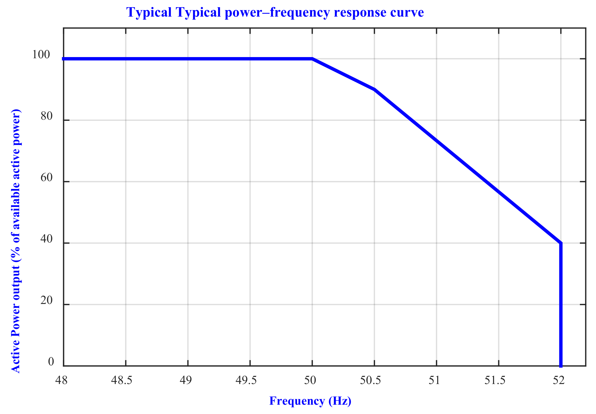
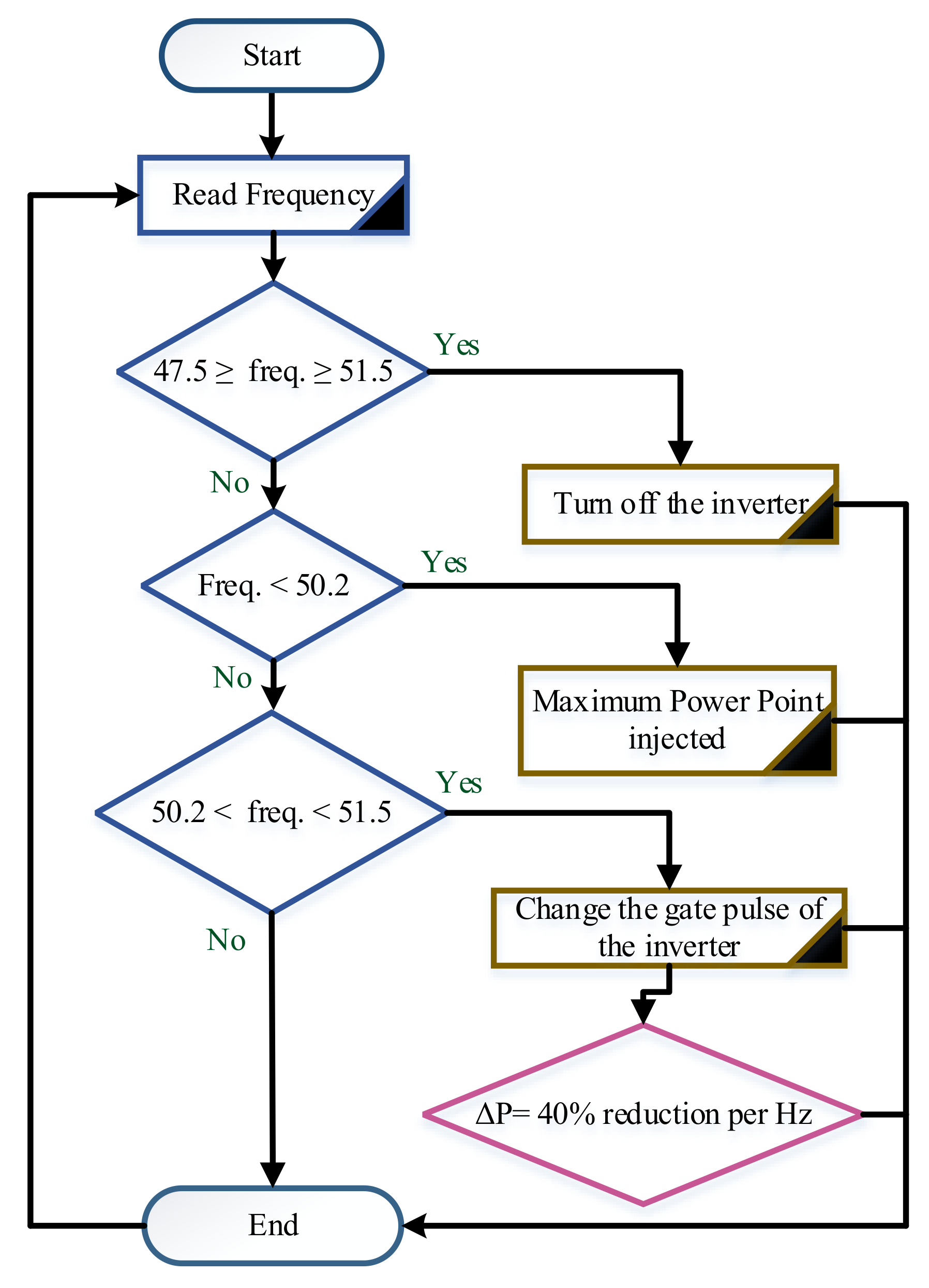
3. Active Power Control

It is well known that the frequency in power systems must stay consistent (50 or 60 Hz). Consequently, at any point in time, the active power supply should be capable of meeting the load demand. When the electrical grid experiences a power imbalance, the frequency deviates from its nominal value. By reducing the amount of active power output fed into the grid, frequency control can be achieved. This capability is referred to as APC. Figure 6 illustrates a typical power–frequency (APC) curve for GCPVs. It demonstrates the necessity of reducing active power when the system’s frequency increases [48].
Based on the German grid code, when the grid frequency exceeds 50.2 Hz till 51.5 Hz, PVPPs are required to decrease the generated active power (P) by a gradient of 40% per Hz of the available PV power, as depicted in Figure 7. If the frequency falls below 50.2 Hz, the PVPP should inject the maximum available power into the utility grid and operate at full capacity [8]. In this study, the German GC will be used as a reference to achieve the APC of the large-scale GCPVs. The controller is designed for this system of supplying solar power into the main distribution line using an inverter that inverts the induced DC voltage and current in solar panels into three phases of AC voltage and current. As a result, the designed controller in this study must supply power into the grid according to the following three cases:
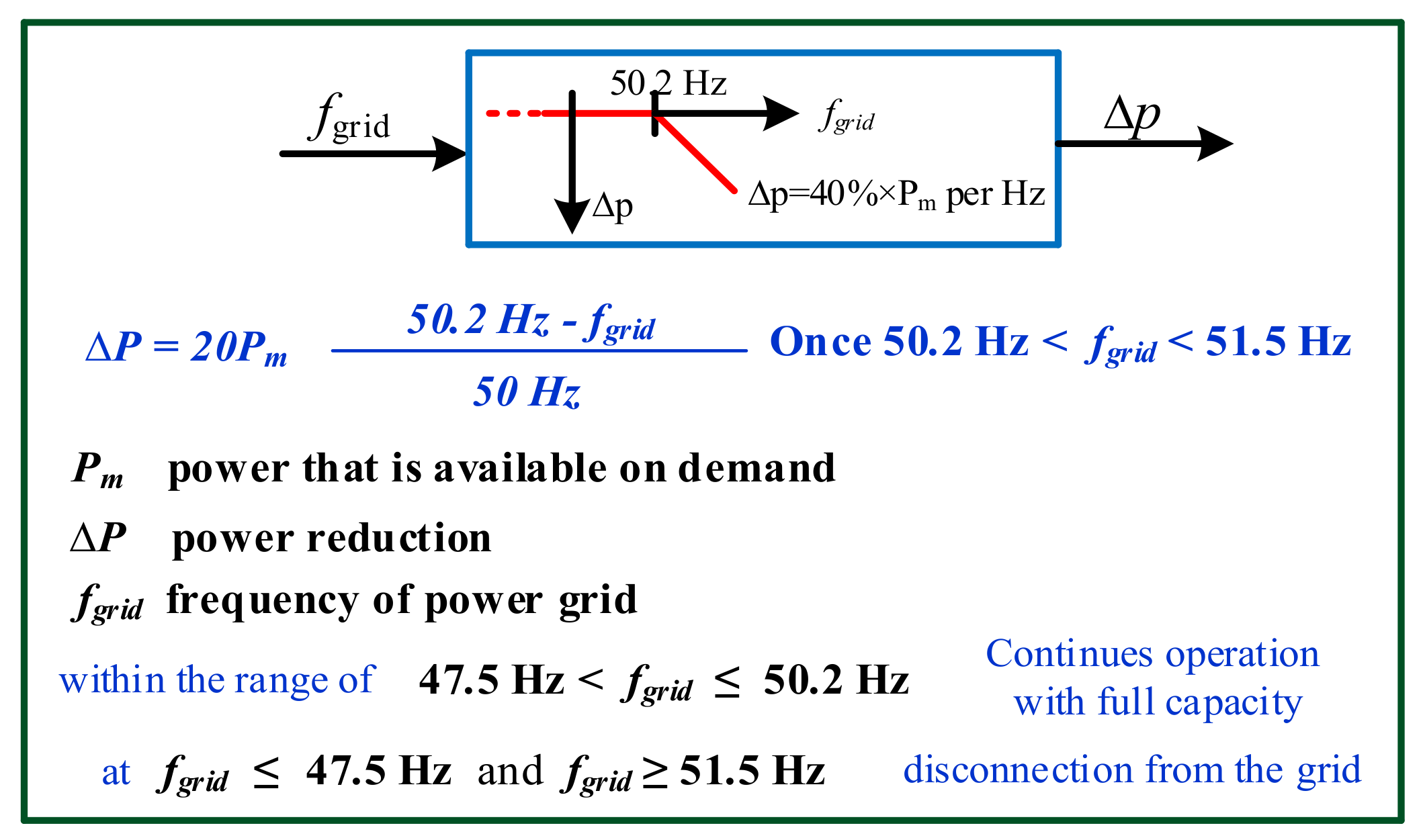
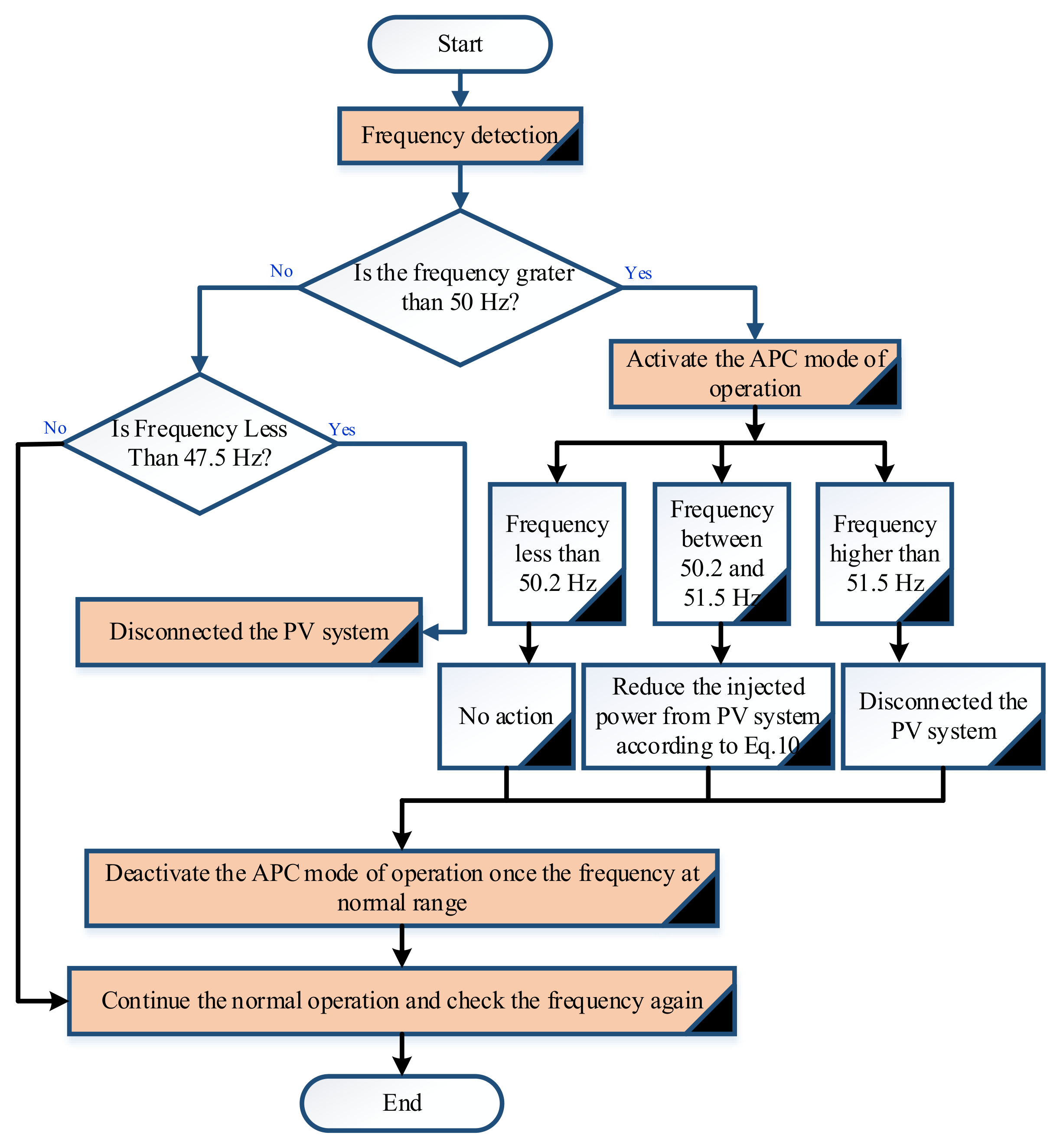
  • First case: if the line frequency is less than 50.2 Hz and greater than 47.5 Hz, the PV output power is totally inverted and supplied into the utility grid.
  • Second case: if the main line frequency increased above 50.2 Hz until 51.5 Hz, the quantity of PV generated injected power into the grid must be decreased according to the following equation:
    Δ P = 20 P m × 50.2   Hz   -   f n e t w o r k 50   Hz
  • Third case: if the main line frequency goes below 47.5 Hz or above 51.5 Hz, the DC power inverted is totally cut.
All the above three cases are achieved using a proportional-integral controller that depends on a sensor that measures the main line frequency. The APC control should be activated accordingly based on the measured value of frequency and the predefined values. The controller should inject the maximum power via connecting all solar panels to the inverter as frequency detected in the first case. However, if the frequency is detected in the second case, the controller sends commands to remove several solar panels that are connected in parallel. However, if the frequency is detected as per the third case, the controller sends commands to turn off the inverter itself. Figure 8 shows the flowchart algorithm of the controller.
The grid voltage is transformed in the d-q coordinate system, while its output generates the commanded VSC voltages. Such an approach allows the full use of the advantages of PI controllers. After backward transformation, the three voltages are delivered to PWM, generating switching signals for an inverter. PI controllers are found in the simulation step response. This non-systematic and hard action becomes more complex and time-consuming, particularly in complex applications. Consequently, the formulation of controller tuning as an optimization problem is a promising resolution. These circuits are composed mostly of a direct current source, a power inductor, a power IGBT, a capacitor, a power diode, a DC voltage sensor power, and a resistor acting as a load. For examining the performance of multi-source chopper circuits, two distinct DC voltage sources are attached to the circuits. This scenario will occur in a real-world environment, such as in photovoltaic power systems. A proportional-integral controller was used to regulate the output voltage of chopper circuits. The output voltage is sensed by the voltage sensor, and its value is returned and compared to the reference value. To control the IGBT switch, errors will indeed be modulated using a triangle carrier signal, as shown in Figure 9. Overall, Figure 10 shows the flowchart of the APC controller operation flow.

4. Results and Discussion

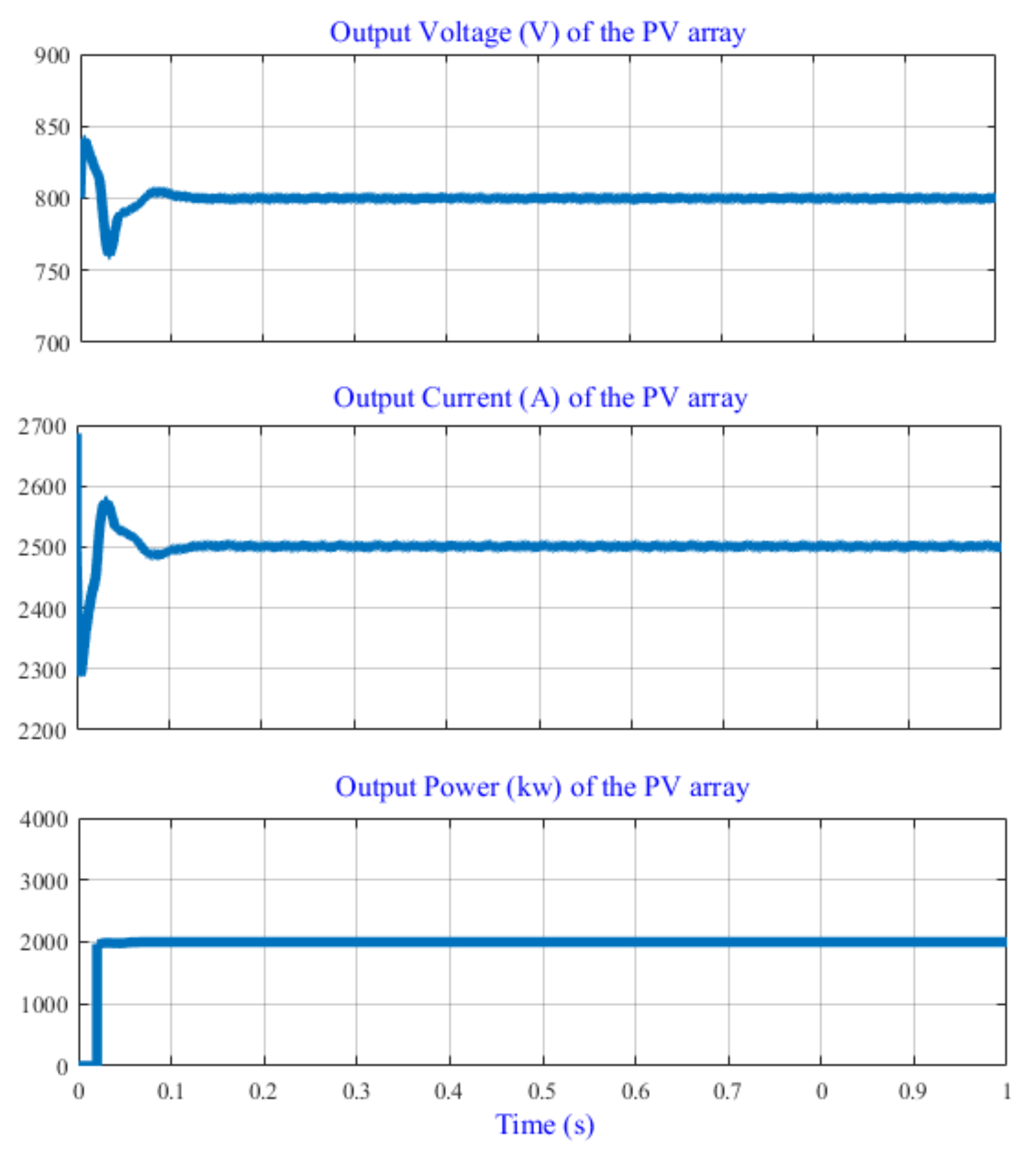
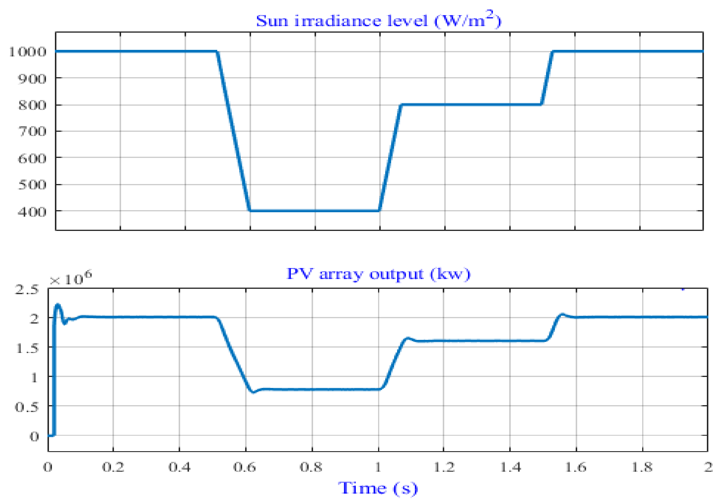
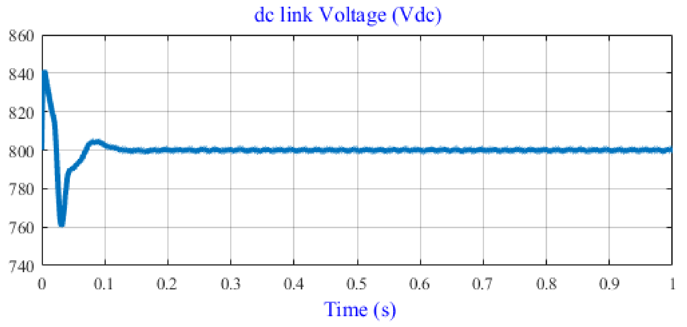
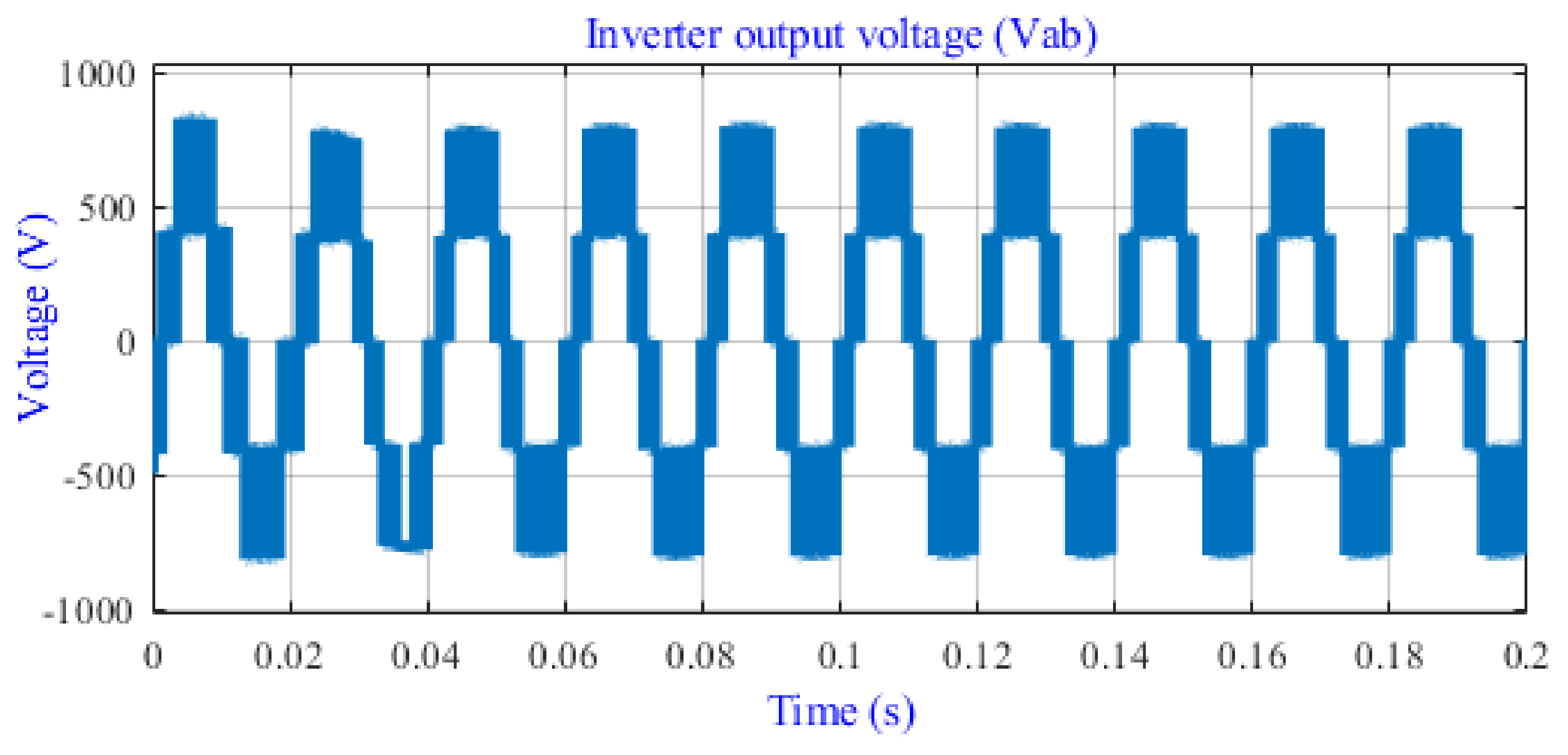
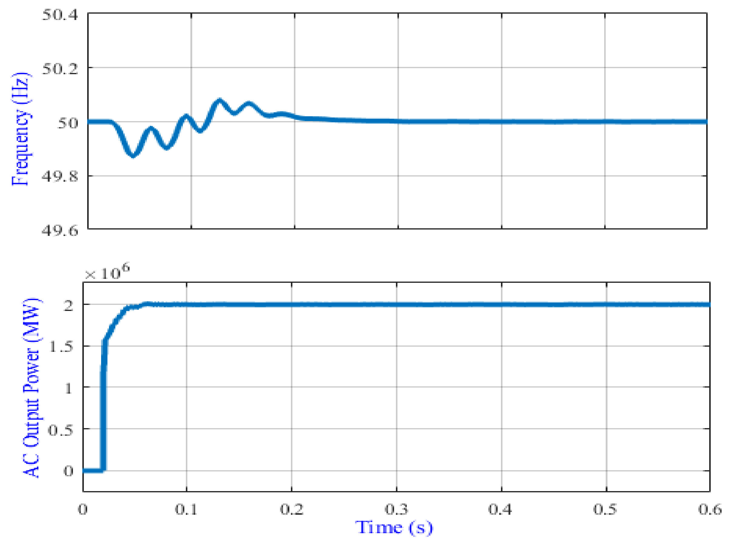
4.1. Simulation Results of the Large-Scale PVPP

Figure 11 illustrates that the PV array can provide 2000 kW of power at STC. In addition, the maximum current and voltage are 2495.46 A and 801.45 V, respectively. These simulation results have proven that the PV array has a true maximum PV array current of Impv = 2495.46 A, maximum PV array voltage of Vmpv = 801.9 V, and an output DC power Pmpp equal to around 2 MW, which complies with the system sizing described above. Figure 12 shows the output power of the PV system at three different levels of radiation. It starts at 1000 W/m2, drops to 400 W/m2, rises to 800 W/m2, and then back to 1000 W/m2 with a temperature of 25 °C. The generated power under STC is around 2000 kW, whereas the maximum power is 800 kW and 1600 kW when the radiation levels are 400 W/m2 and 800 W/m2, respectively. In conclusion, the simulation results based on the mathematical modeling described above have been matched.
A large-scale single-stage PV power plant should use a DC-link with a value close to the optimum voltage of the system array to minimize output current ripple and provide a stable DC supply for grid inverter operation [49]. The DC-link comprises of two capacitors, C1 and C2, which are split into ± 400 V. As the array’s open-circuit voltage (Voc = 938.3 V) falls within the inverter voltage range, the inverter operates at the same nominal voltage as the DC-link and must be compatible with the array’s current and voltage to sustain its maximum values. Thus, the DC-link voltage was designed with 800 V in this research, as shown in Figure 13. This voltage matched the output voltage of the PV array (801.9 V).
In Figure 14, the inverter’s output voltage is shown as an unfiltered output with switching effects. Through zero, the amplitude of the peak voltage switched between −800 V and +800 V. The output of the inverter will flip from the positive to the negative peak of the DC-link voltage when all the parameters in the inverter reach a steady state. This voltage is then filtered using a filter developed specifically for this investigation to reduce distortions.

4.2. Simulation Results of the APC

The generation units have a very important role in controlling their injected output power when the frequency deviates from 50 Hz (e.g., because of a loss-of-loads event or faults). As described earlier, the ability to reduce the increase in grid frequency by more than 50.2 Hz is achieved by reducing the output power through active power control. APC is one of the issues that large-scale PV power stations confront while integrating into the electrical grid, and it has yet to be completely researched. Therefore, this section presents the results of the comprehensive control strategy of PVPP to improve the APC capability following the standards requirements and modern GCs interconnection rules. Using Matlab/Simulink, the whole GCPVS model previously described is used to test the proposed APC control technique. The PV power plant system is linked to the MV with an optimal voltage of 11 kV. The following case studies show the results of the APC with different levels of frequency deviation. Therefore, a suitable amount of active power is reduced during the deviation according to the standard requirements described. It is worth mentioning that all tests have been done at STC.

4.2.1. Normal Operation

To maintain grid frequency stability, the generation capacity should be equal to the necessary load. If this is not done, frequency issues may arise, which could also result in the service being disconnected. Changes in the supply and demand of electricity have the potential to have a significant impact on the frequency of the networks. For instance, if demand for electricity exceeds supply, the frequency will decrease. On the other hand, if there is too much supply, the frequency will increase. In a normal case, the frequency should oscillate around 50 Hz and then the supplied power should stay at the normal level. This case is shown in Figure 15 in which the PVPP should supply the grid with 2 MW and the frequency is stable at 50 Hz.

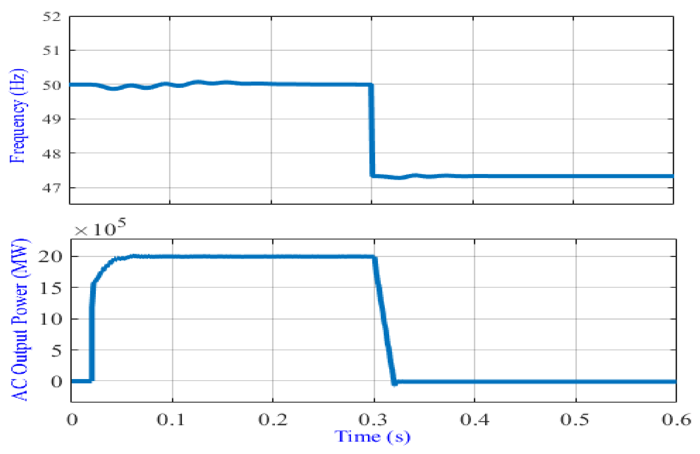
4.2.2. Frequency Less Than 47.5 Hz

According to the new requirements of grid codes, if the grid frequency is at 50 Hz, the PV power plant should inject the maximum available power into the power grid. However, if the grid frequency decreases to less than 47.5 Hz, the PV power plant should speedily disconnect from the utility grid for safety. To test the effectiveness of the developed control according to the standards requirements, a fault occurred at the distribution system for 0.3 s, leading the frequency to decrease to 47.4 Hz. As can be seen in Figure 16, the output power is equal to 2 MW (full generation capacity) once the grid frequency is at 50 Hz. This is the normal case where the grid is at the normal mood of operation, and the controller takes no action. However, once the fault is activated, the frequency drops to less than 47.5 Hz and thus, the PV power plant is disconnected accordingly, which meets the standard requirements stated by the grid codes.

4.2.3. Frequency Ranging from 50.2–51.5 Hz
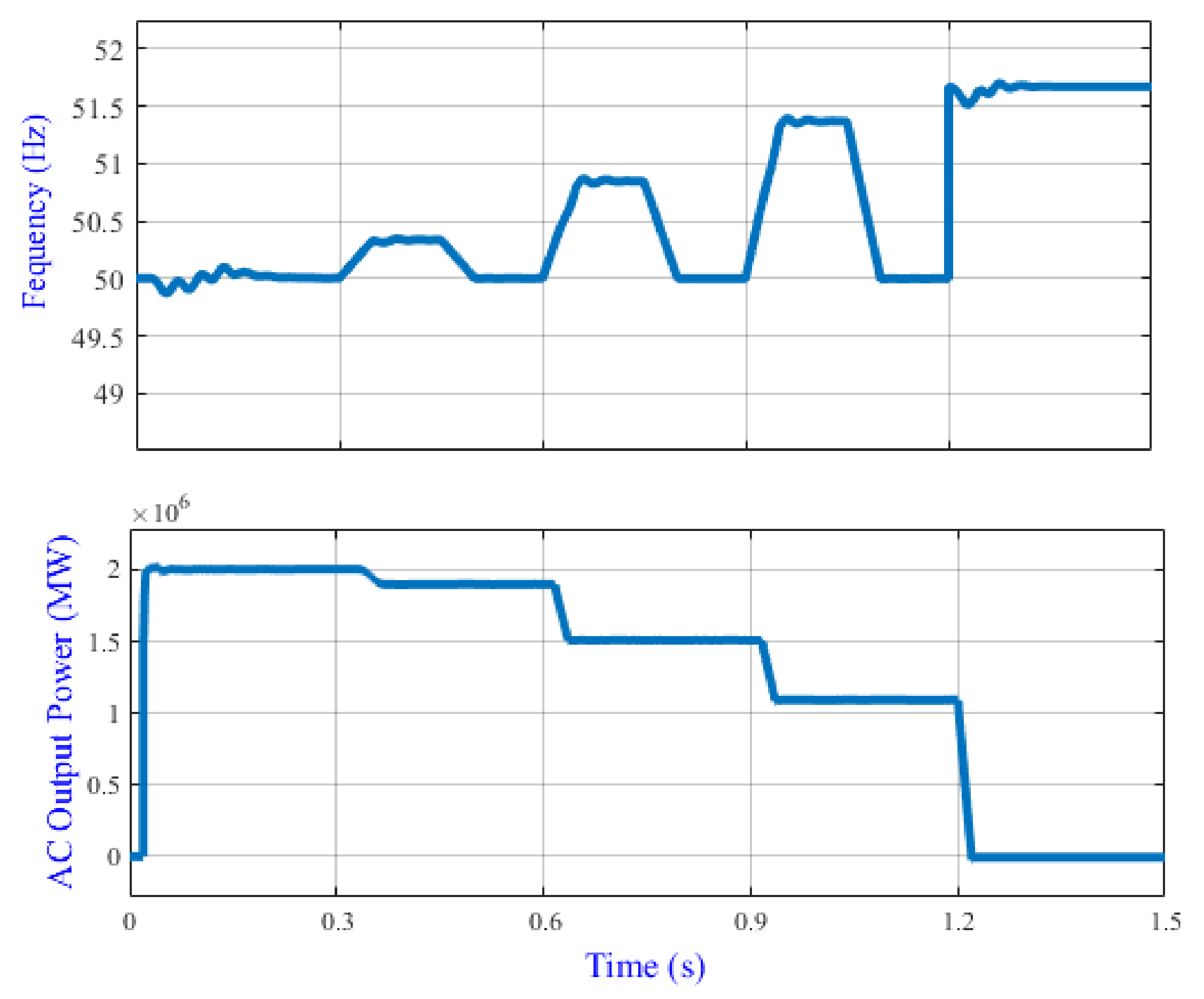
For grid frequency stability, in the case that frequency is between 50.2 Hz and 51.5 Hz, the APC should act and decrease the power injected into the power grid accordingly and thus stabilize the frequency at normal range (50 Hz). In this case, different scenarios are tested below, and the results are shown in Figure 17.
(1)
From 0 to 0.3 s, the frequency is in the range of 50 Hz and therefore there is no action done by the controller.
(2)
From 0.3 s to 0.5 s the frequency is increased up to 50.3 Hz, so the APC is activated, and the output power is reduced by around 80 kW and the PV power plant supplies the grid with 1.92 MW. Thus, the frequency recovers to nominal operation between 0.5 s and 0.6 s.
Δ p = 20 × 50.2 50.3 50 × 2 × 10 6 = 80000 80000 + 2 × 10 6 = 1.92 MW
(3)
From 0.6 s to 0.8 s the frequency is increased up to 50.8 Hz, so the APC is activated, and the output power is reduced by around 480 kW and the PV power plant supplies the grid with 1.52 MW. Thus, the frequency recovers to nominal value between 0.8 s and 0.9 s.
Δ p = 20 × 50.2 50.8 50 × 2 × 10 6 = 480000 480000 + 2 × 10 6 = 1.52 MW
(4)
From 0.9 s to 1.1 s the frequency is increased up to 51.3 Hz, so the APC is activated, and the output power is reduced by around 880 kW and the PV power plant supplies the grid with 1.12 MW. Thus, the frequency recovers to nominal value between 1.1 s and 1.2 s.
Δ p = 20 × 50.2 51.3 50 × 2 × 10 6 = 880000 880000 + 2 × 10 6 = 1.12 MW
(5)
At 1.2 s, the frequency is increased to above 51.5 Hz, and then the APC is activated to disconnect the PV power plant.

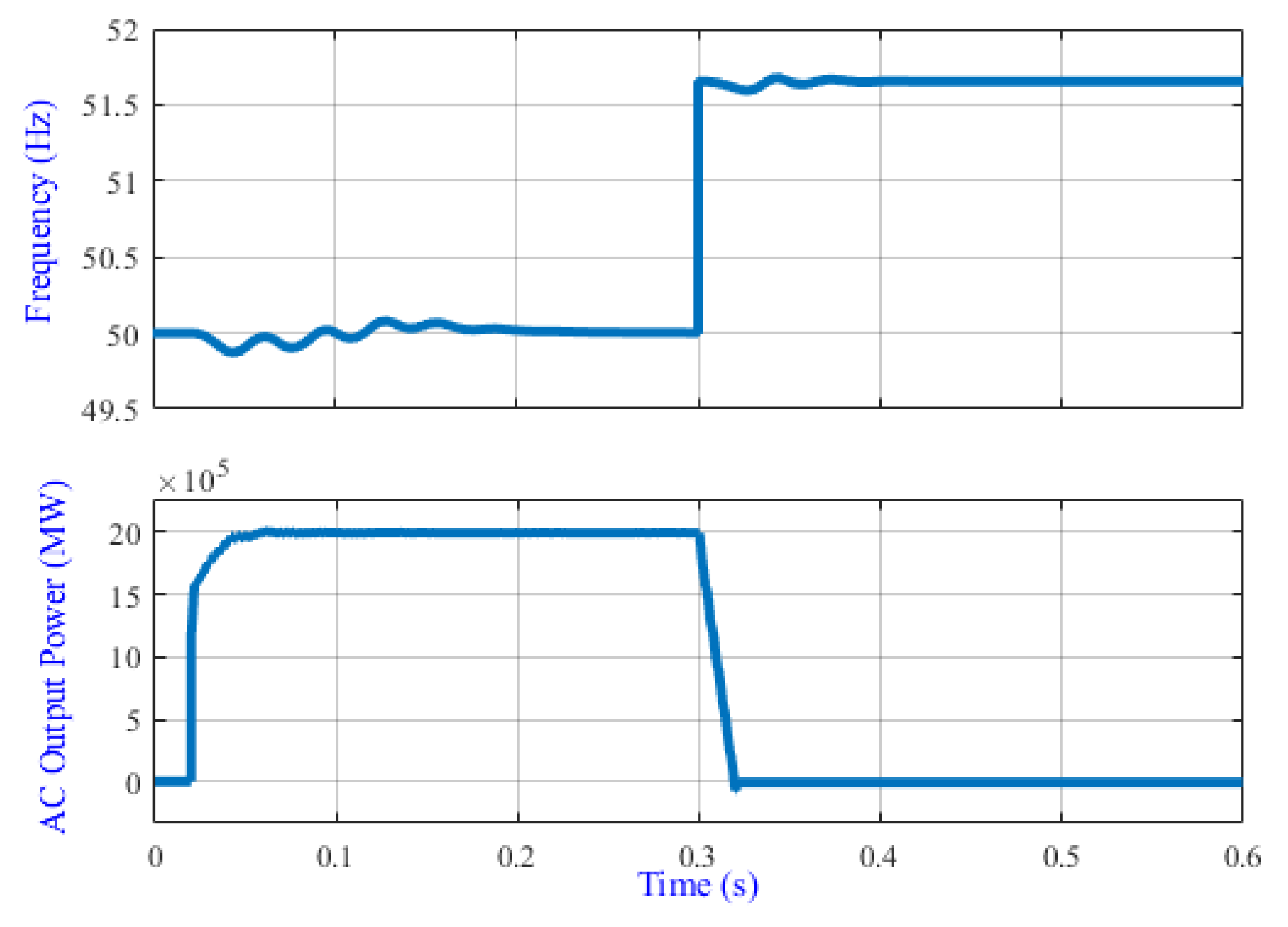
4.2.4. Frequency Higher Than 51.5 Hz

For safety concerns, the disconnection of the system should happen when the frequency increases to more than 51.5 Hz. Therefore, the APC should act and disconnect the PV power plant. Figure 18 shows the effectiveness of the proposed control in which the PVPP is disconnected accordingly.

4.2.5. Different Rates of Changes of the Frequency at Same Time

To show the effectiveness of the system operation with APC more clearly, the frequency has deviated either up or down and the output power followed this increasing and decreasing accordingly (as per APC requirements). To enhance the system safety, the grid will disconnect when the frequency reaches a value above 51.5 Hz and below 47.5 Hz. All the cases (cases 1 to 4) are summarized in Figure 19. It can be noticed that the APC is working effectively to stabilize the grid frequency according to the new standard requirements.
By comparing the results of the introduced APC strategy with the recent studies, the proposed method showed good performance, simplicity, and met the grid-code standard requirements. In sum, the presented results were compatible with the recent requirements, which is an important indicator of the results’ verification. In addition, as compared to existing methods described in Table 3, the proposed method effectively enhanced the frequency stability at different levels of frequency deviation with possible low complexity. Table 3 shows a comparison between the existing and proposed methods.

5. Conclusions

Based on frequency stability requirements as result of the growing integration of PV power systems into electrical power grids, a large-scale, 3-ph PV power plant (PVPP) connected to a utility grid under frequency deviation was examined in this study. The primary goals of this research were to construct a high-efficiency grid-connected PV system and to develop advanced frequency control, namely active power control (APC). The APC allowed the PVPP to resist grid disruptions while maintaining a regular frequency range to improve the grid-connected PV system’s efficiency and grid frequency stability. Moreover, the APC aimed to make the PVPPs operate similar to conventional power plants and help restore the frequency in the event of disturbances.
To achieve this goal, the inverter operated in two modes: steady-state mode with a normal frequency (50 Hz) and abnormal mode when the frequency increases or decreases away from 50 Hz. APC is activated to stabilize the frequency, in the case of a disturbance. To apply the APC capability control based on the standard requirements, the design and development of large-scale PVPP integrated into medium- and low-voltage networks have been achieved. The APC method introduced some amendments to allow the PVPP to ride through the frequency disturbances according to the requirements of the standards imposed by different grid codes. These adjustments include a frequency-detection unit to inform the control to convert from normal operation mode into a disturbance mode of operation. When the system is switched to grid disturbance operation mode, the proposed control is effective because it allows the PVPP to continue producing power while reducing frequency increase. Additionally, once the disturbance is cleared, all parameters are restored to their pre-disturbance levels and ride through the frequency increase smoothly.
This control also achieved an essential feature imposed by some GCs for enhancing the APC capability via reducing the active power injected into the power network to support power grid and frequency recovery. Consequently, the grid-connected PVPP offered ancillary capability during frequency deviation via APC. These ancillary services can doubtlessly prevent cascading events, which can cause blackouts, and enhance the recovery process from the disturbance event, improving power–frequency stability.
The simulation results validated the proposed control ability to solve transient behavior and ride through the frequency. It is shown that the proposed control methods have excellent performance in terms of frequency detection, keeping the inverter connected or disconnected based on frequency situation, and reducing the amount of active power (for frequency ranging from 50.2–51.5 Hz) to support frequency recovery until different types of disturbance are safely ridden through, as demonstrated by simulations of various scenarios. It can be concluded that the proposed APC is effective to help the PVPP behave similar to a traditional power plant for a stable, reliable, and efficient future of the PV system-connected power grid.

Author Contributions

Conceptualization: A.Q.A.-S. and W.K.I.; Investigation: R.F.A., T.S.U., H.M.K.A.-M., K.A., M.G.M.A. and M.A.A.; Project Administration: T.S.U. and A.Q.A.-S.; Resources: W.K.I., R.F.A. and H.M.K.A.-M.; Supervision: T.S.U., A.Q.A.-S. and M.A.A.; Visualization: H.M.K.A.-M., T.S.U., K.A. and M.G.M.A.; Writing—Original Draft: A.Q.A.-S. and W.K.I.; Writing—Review and Editing: H.M.K.A.-M., T.S.U., A.Q.A.-S. and K.A.; Funding Acquisition: T.S.U. All authors have read and agreed to the published version of the manuscript.

Funding

This research received no external funding.

Institutional Review Board Statement

Not applicable.

Informed Consent Statement

Not applicable.

Data Availability Statement

Not applicable.

Conflicts of Interest

The authors declare that they have no known competing financial interest or personal relationships that could have appeared to influence the work reported in this paper.

References

  1. Nkiriki, J.; Ustun, T.S. Mini-grid policy directions for decentralized smart energy models in Sub-Saharan Africa. In Proceedings of the 2017 IEEE PES Innovative Smart Grid Technologies Conference Europe (ISGT-Europe), Turin, Italy, 26–29 September 2017; pp. 1–6. [Google Scholar]
  2. Javed, K.; Ashfaq, H.; Singh, R.; Hussain, S.M.S.; Ustun, T.S. Design and Performance Analysis of a Stand-alone PV System with Hybrid Energy Storage for Rural India. Electronics 2019, 8, 952. [Google Scholar] [CrossRef] [Green Version]
  3. Dos Santos, F.C.; Thornburg, J.; Ustun, T.S. Automated Planning of Rooftop PV Systems with Aerial Image Processing. In Proceedings of the 2018 IEEE PES Asia-Pacific Power and Energy Engineering Conference (APPEEC), Kota Kinabalu, Malaysia, 7–10 October 2018; pp. 736–740. [Google Scholar]
  4. Oteng, D.; Zuo, J.; Sharifi, E. A scientometric review of trends in solar photovoltaic waste management research. Sol. Energy 2021, 224, 545–562. [Google Scholar] [CrossRef]
  5. International Renewable Energy Agency. IRENA Renewable Power Capacity Growth. Available online: https://bit.ly/3Gs9jRJ (accessed on 1 February 2022).
  6. Japan Electrical Safety and Environment Technology Laboratories, Low-Voltage Grid-Connected Inverter Certification. Available online: https://www.jet.or.jp/en/products/protection/index.html (accessed on 4 February 2022).
  7. Panigrahi, R.; Mishra, S.K.; Srivastava, S.C.; Srivastava, A.K.; Schulz, N.N. Grid integration of small-scale photovoltaic systems in secondary distribution network—A review. IEEE Trans. Ind. Appl. 2020, 56, 3178–3195. [Google Scholar] [CrossRef]
  8. Al-Shetwi, A.Q.; Sujod, M.Z. Grid-connected photovoltaic power plants: A review of the recent integration requirements in modern grid codes. Int. J. Energy Res. 2018, 42, 1849–1865. [Google Scholar] [CrossRef]
  9. Ustun, T.S.; Sugahara, S.; Suzuki, M.; Hashimoto, J.; Otani, K. Power Hardware in-the-Loop Testing to Analyze Fault Behavior of Smart Inverters in Distribution Networks. Sustainability 2020, 12, 9365. [Google Scholar] [CrossRef]
  10. Cheng, Y.; Azizipanah-Abarghooee, R.; Azizi, S.; Ding, L.; Terzija, V. Smart frequency control in low inertia energy systems based on frequency response techniques: A review. Appl. Energy 2020, 279, 115798. [Google Scholar] [CrossRef]
  11. Tayyebi, A.; Groß, D.; Anta, A.; Kupzog, F.; Dörfler, F. Frequency stability of synchronous machines and grid-forming power converters. IEEE J. Emerg. Sel. Top. Power Electron. 2020, 8, 1004–1018. [Google Scholar] [CrossRef] [Green Version]
  12. Hashimoto, J.; Ustun, T.S.; Suzuki, M.; Sugahara, S.; Hasegawa, M.; Otani, K. Advanced Grid Integration Test Platform for Increased Distributed Renewable Energy Penetration in Smart Grids. IEEE Access 2021, 9, 34040–34053. [Google Scholar] [CrossRef]
  13. Honrubia-Escribano, A.; Ramirez, F.J.; Gómez-Lázaro, E.; Garcia-Villaverde, P.M.; Ruiz-Ortega, M.J.; Parra-Requena, G. Influence of solar technology in the economic performance of PV power plants in Europe. A comprehensive analysis. Renew. Sustain. Energy Rev. 2018, 82, 488–501. [Google Scholar] [CrossRef]
  14. Christie, R.D.; Bose, A. Load frequency control issues in power system operations after deregulation. IEEE Trans. Power Syst. 1996, 11, 1191–1200. [Google Scholar] [CrossRef]
  15. Datta, M.; Senjyu, T.; Yona, A.; Funabashi, T.; Kim, C.-H. A frequency-control approach by photovoltaic generator in a PV–diesel hybrid power system. IEEE Trans. Energy Convers. 2011, 26, 559–571. [Google Scholar] [CrossRef]
  16. Liu, L.; Li, H.; Xue, Y.; Liu, W. Decoupled active and reactive power control for large-scale grid-connected photovoltaic systems using cascaded modular multilevel converters. IEEE Trans. Power Electron. 2015, 30, 176–187. [Google Scholar]
  17. Stimoniaris, D.; Tsiamitros, D.; Dialynas, E. Improved energy storage management and PV-active power control infrastructure and strategies for microgrids. IEEE Trans. Power Syst. 2016, 31, 813–820. [Google Scholar] [CrossRef]
  18. Latif, A.; Hussain, S.M.S.; Das, D.C.; Ustun, T.S. Optimum Synthesis of a BOA Optimized Novel Dual-Stage PI − (1 + ID) Controller for Frequency Response of a Microgrid. Energies 2020, 13, 3446. [Google Scholar] [CrossRef]
  19. Bullich-Massagué, E.; Aragüés-Peñalba, M.; Sumper, A.; Boix-Aragones, O. Active power control in a hybrid PV-storage power plant for frequency support. Sol. Energy 2017, 144, 49–62. [Google Scholar] [CrossRef] [Green Version]
  20. Yang, Y.; Enjeti, P.; Blaabjerg, F.; Wang, H. Suggested grid code modifications to ensure wide-scale adoption of photovoltaic energy in distributed power generation systems. In Proceedings of the Industry Applications Society Annual Meeting, Lake Buena Vista, FL, USA, 6–11 October 2013; pp. 1–8. [Google Scholar]
  21. Troester, E. New German grid codes for connecting PV systems to the medium voltage power grid. In Proceedings of the 2nd International Workshop on Concentrating Photovoltaic Power Plants: Optical Design, Production, Grid Connection, Darmstadt, Germany, 9–10 March 2009; pp. 9–10. [Google Scholar]
  22. Gevorgian, V.; Booth, S. Review of Technical Requirements for Interconnecting Wind and Solar Generation; National Renewable Energy Laboratory: Golden, CO, USA, 2013. [Google Scholar]
  23. Energy Commission Malaysia (ECM). Grid Code for Peninsular Malaysia. Available online: http://st.gov.my (accessed on 16 June 2021).
  24. Wu, Y.-K.; Chang, S.-M.; Mandal, P. Grid-connected wind power plants: A survey on the integration requirements in modern grid codes. IEEE Trans. Ind. Appl. 2019, 55, 5584–5593. [Google Scholar] [CrossRef]
  25. Liu, Y.; Zhu, L.; Zhan, L.; Gracia, J.R.; King, T., Jr.; Liu, Y. Active power control of solar PV generation for large interconnection frequency regulation and oscillation damping. Int. J. Energy Res. 2016, 40, 353–361. [Google Scholar] [CrossRef]
  26. Zhang, Y.; Ma, L.; Zheng, T.Q. Application of feedback linearization strategy in voltage fault ride-through for photovoltaic inverters. In Proceedings of the IECON 2011-37th Annual Conference on IEEE Industrial Electronics Society, Melbourne, VIC, Australia, 7–10 November 2011; pp. 4666–4671. [Google Scholar]
  27. Jayakrishnan, R.; Sruthy, V. In Fault ride through augmentation of microgrid, Advancements in Power and Energy (TAP Energy). In Proceedings of the 2015 International Conference on Technological Advancements in Power and Energy (TAP Energy), Kollam, India, 24–26 June 2015; pp. 357–362. [Google Scholar]
  28. Rath, D.; Kar, S.; Patra, A.K. Harmonic distortion assessment in the single-phase photovoltaic (PV) system based on spwm technique. Arab. J. Sci. Eng. 2021, 41, 9601–9615. [Google Scholar] [CrossRef]
  29. Nour, A.M.; Helal, A.A.; El-Saadawi, M.M.; Hatata, A.Y. A control scheme for voltage unbalance mitigation in distribution network with rooftop pv systems based on distributed batteries. Int. J. Electr. Power Energy Syst. 2021, 124, 106375. [Google Scholar] [CrossRef]
  30. Yang, F.; Ling, Z.; Wei, M.; Mi, T.; Yang, H.; Qiu, R.C. Real-time static voltage stability assessment in large-scale power systems based on spectrum estimation of phasor measurement unit data. Int. J. Electr. Power Energy Syst. 2021, 124, 106196. [Google Scholar] [CrossRef]
  31. Hoke, A.F.; Shirazi, M.; Chakraborty, S.; Muljadi, E.; Maksimovic, D. Rapid active power control of photovoltaic systems for grid frequency support. IEEE J. Emerg. Sel. Top. Power Electron. 2017, 5, 1154–1163. [Google Scholar] [CrossRef]
  32. Kikusato, H.; Ustun, T.S.; Hashimoto, J.; Otani, K. Aggregate Modeling of Distribution System with Multiple Smart Inverters. In Proceedings of the 2019 International Conference on Smart Energy Systems and Technologies (SEST), Porto, Portugal, 9–11 September 2019; pp. 1–6. [Google Scholar]
  33. Ustun, T.S.; Aoto, Y. Analysis of Smart Inverter’s Impact on the Distribution Network Operation. IEEE Access 2019, 7, 9790–9804. [Google Scholar] [CrossRef]
  34. Long, J.; Qu, L.; Zhang, S.; Li, L. In Frequency control strategy and test technology of photovoltaic power plant. In Proceedings of the 2019 IEEE 3rd Conference on Energy Internet and Energy System Integration (EI2), Changsha, China, 8–10 November 2019; pp. 1695–1698. [Google Scholar]
  35. Chen, Z.; Liu, J.; Lin, Z.; Duan, Z. Closed-loop active power control of wind farm based on frequency domain analysis. Electr. Power Syst. Res. 2019, 170, 13–24. [Google Scholar] [CrossRef]
  36. Madorell-Batlle, Q.; Bullich-Massagué, E.; Cheah-Mañé, M.; Gomis-Bellmunt, O. Over-frequency support in large-scale photovoltaic power plants using non-conventional control architectures. Int. J. Electr. Power Energy Syst. 2021, 127, 106679. [Google Scholar] [CrossRef]
  37. Padhy, S.; Sahu, P.R.; Khadanga, R.K.; Prusty, B.R.; Panda, S. MPA-Tuned Fractional Order PID Controller for Frequency Control of Interconnected Smart Grid Power System. In Proceedings of the 2021 Innovations in Power and Advanced Computing Technologies (i-PACT), Kuala Lumpur, Malaysia, 27–29 November 2021; pp. 1–5. [Google Scholar]
  38. Latif, A.; Hussain, S.S.; Das, D.C.; Ustun, T.S.; Iqbal, A. A review on fractional order (FO) controllers’ optimization for load frequency stabilization in power networks. Energy Rep. 2021, 7, 4009–4021. [Google Scholar] [CrossRef]
  39. Howlader, A.M.; Sadoyama, S.; Roose, L.R.; Chen, Y. Active power control to mitigate voltage and frequency deviations for the smart grid using smart PV inverters. Appl. Energy 2020, 258, 114000. [Google Scholar] [CrossRef]
  40. Olita, F. Advanced Control and Condition Monitoring PV Systems. Master Thesis, Aalborg University Institute of Energy Technology Denmark, Aalborg, Denmark, 2012. [Google Scholar]
  41. Jana, J.; Saha, H.; Bhattacharya, K.D. A review of inverter topologies for single-phase grid-connected photovoltaic systems. Renew. Sustain. Energy Rev. 2016, 72, 1256–1270. [Google Scholar] [CrossRef]
  42. Al-Shetwi, A.Q. Design and economic evaluation of electrification of small villages in rural area in Yemen using stand-alone PV system. Int. J. Renew. Energy Res. (IJRER) 2016, 6, 289–298. [Google Scholar]
  43. Menzi, D.; Kolar, J.W.; Anderson, J.A.; Kasper, M.J. New third-harmonic injection modulation reducing the dc-link energy buffer requirement of phase-modular three-phase isolated pfc ac/dc converter systems. In Proceedings of the 2021 IEEE 22nd Workshop on Control and Modelling of Power Electronics (COMPEL), Cartagena, Colombia, 2–5 November 2021. [Google Scholar]
  44. Basso, T. IEEE 1547 and 2030 Standards for Distributed Energy Resources Interconnection and Interoperability with the Electricity Grid; National Renewable Energy Lab. (NREL): Golden, CO, USA, 2014. [Google Scholar]
  45. Orłowska-Kowalska, T.; Blaabjerg, F.; Rodríguez, J. Advanced and Intelligent Control in Power Electronics and Drives; Springer: New York, NY, USA, 2014; Volume 531. [Google Scholar]
  46. Villalva, M.G.; Gazoli, J.R.; Ruppert Filho, E. Comprehensive approach to modeling and simulation of photovoltaic arrays. IEEE Trans. Power Electron. 2009, 24, 1198–1208. [Google Scholar] [CrossRef]
  47. Nwaigwe, K.; Mutabilwa, P.; Dintwa, E. An overview of solar power (PV systems) integration into electricity grids. Mater. Sci. Energy Technol. 2019, 2, 629–633. [Google Scholar] [CrossRef]
  48. Ali, Q.; Muhamad Zahim, S.; Noor Lina, R. A review of the fault ride through requirements in different grid codes concerning penetration of PV system to the electric power network. ARPN J. Eng. Appl. Sci. 2015, 10, 9906–9912. [Google Scholar]
  49. Lee, J.-S.; Lee, K.B. Variable dc-link voltage algorithm with a wide range of maximum power point tracking for a two-string PV system. Energies 2013, 6, 58–78. [Google Scholar] [CrossRef] [Green Version]
Figure 1. Growth trend of PV energy 2010–2020.
Energies 15 02035 g001
Figure 2. Large-scale PV power station interconnected to the utility grid.
Energies 15 02035 g002
Figure 3. The PVPP array configuration.
Energies 15 02035 g003
Figure 4. Synchronized rotating frame control of the three-phase three-level inverter: Schematic diagram.
Energies 15 02035 g004
Figure 5. Three-phase view of a grid-connected voltage source inverter.
Energies 15 02035 g005
Figure 6. Controlling active power in a typical manner via frequency control.
Energies 15 02035 g006
Figure 7. The reduction in active power in the event of an over-frequency.
Energies 15 02035 g007
Figure 8. Flowchart algorithm of controller.
Energies 15 02035 g008
Figure 9. Controller structure of the APC-based grid-connected PV system.
Energies 15 02035 g009
Figure 10. The system flowchart containing controller structure of the PV system with APC.
Energies 15 02035 g010
Figure 11. The PVPP array output at STC.
Energies 15 02035 g011
Figure 12. Output power of the PVPP array (dc generators) at different levels of radiation.
Energies 15 02035 g012
Figure 13. DC-link voltage of the PVPP.
Energies 15 02035 g013
Figure 14. Inverter voltage (Vab).
Energies 15 02035 g014
Figure 15. Active power control behavior during normal frequency.
Energies 15 02035 g015
Figure 16. Active power control behavior during normal and less than 47.5 Hz frequency.
Energies 15 02035 g016
Figure 17. Active power control behavior during different levels of frequency disturbances.
Energies 15 02035 g017
Figure 18. Active power control behavior during normal frequency and the frequency greater than 51.5 Hz.
Energies 15 02035 g018
Figure 19. Active power control behavior during frequency deviation.
Energies 15 02035 g019
Table 1. SunPower SPR-435 NE-WHT-D module specifications.
The ParametersThe ValueThe ParametersThe Value
Maximum powerPmax = 435.21 WNumbers of cells per moduleNcell = 128
Maximum currentImp = 5.97 ATemperature coefficient of Iscαi = 0.0307/Cº
Maximum voltageVmp = 72.9 VTemperature coefficient of Vocαv = −0.0229/Cº
Short-circuit currentIsh = 6.43 AParallel and series resistance (Rp,Rs)419.77 Ω, 0.537 Ω
Open-circuit voltageVoc = 85.6 VIdeally factor of the diodem = 0.872
Table 2. Overview of the most important parameters of the inverter-connected power grid.
Inverter ParametersThe Value
Grid voltage (Vg)11 kV
Grid frequency (f)50 Hz
Voltage of DC-link (Vdc)800 V
Capacitor of DC-link (Cdc)0.2130 F
Grid angular frequency (ɷ)2π × 50 rad/s
Filter parameters (R and L)1.25 Ω, 0.1 mH
inverter Switching frequency (fs)2 kHz
Current loop parameter of PI (Kp, Ki)0.3, 20
Voltage loop parameter of PI (Kp, Ki)2, 400
Transformer (n = Vp/Vs)0.4/11 kV
Table 3. Comparison between the proposed and existing methods.
Ref.ControllerMain FindingLimitation/Remarks
[19]Direct ramp rate controlThe frequency drop is supported using an energy storage device (battery to fulfill grid requirements).Power oscillations could occur.
Power ripple in the MPP.
Extra device and then extra cost.
Low response
[34]frequency droop control strategyPV power plant has a good performance on frequency droop control.ACP concept according to the standard requirements not taken into consideration.
[35]Close-loop controlEnhance the wind turbine disturbance suppression capability and power tracking dynamic performance during frequency deviation at the connection point.Studied the effect of frequency impacts on the operation of wind turbine.
Overlooked the power reduction based on grid frequency deviation.
[36]Hierarchical control architectureThe proposed control obtained a fast and accurate response and was robust against communication failures.More focus is paid on the fast response rather than the achievement of grid-code requirements and APC.
Cannot support the operation under different faults.
Proposed APCActive power control using grid-forming invertersEnforce the PV system to behave similar to a traditional power plant during frequency deviation towards frequency stability.The proposed APC is effective to help the PVPP behave similar to a traditional power plant for a stable, reliable, and efficient future of PV systems-connected power grid.
Publisher’s Note: MDPI stays neutral with regard to jurisdictional claims in published maps and institutional affiliations.

