
Virtual Prototyping of the Cement Transporter Including Strength Criterion Based on Geotechnical Boundary Conditions

 , , , and
Abstract
:1. Introduction
2. Materials and Methods
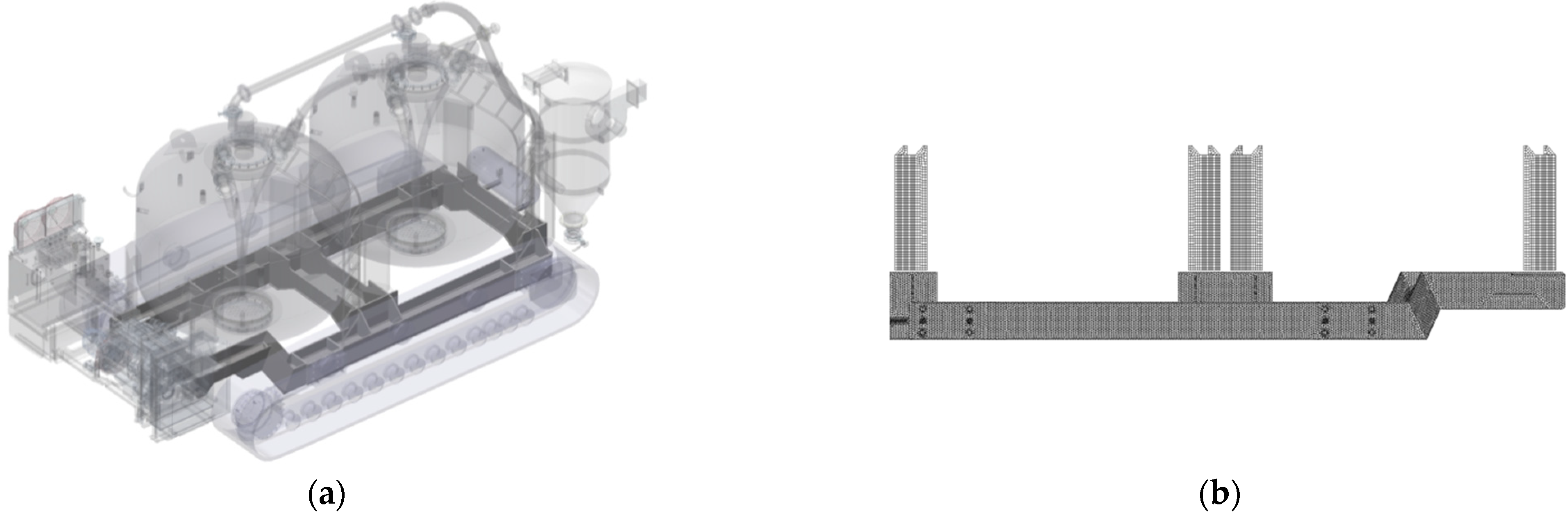
2.1. CAD 3D Models
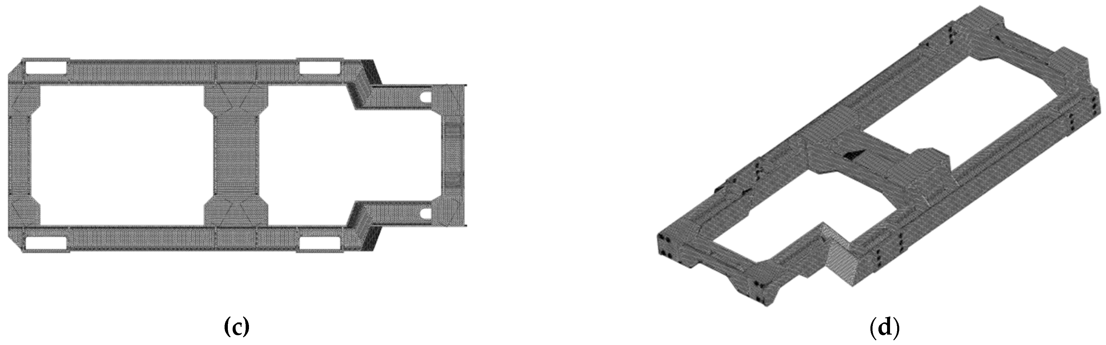
2.2. FEM Computational Models
2.2.1. D Mesh
- Aspect: ratio of the height of the element to the square root of the opposing face area.
- Edge angle: the absolute value of the angle between the two faces meeting at an edge, subtracted from 70.529°.
- Face skew (carried out for each triangular face of the tetrahedral element)—two vectors are constructed: one from a vertex to the mid-point of the opposite edge, and the other between the mid-points of the adjacent edges. The difference results from the angle between these two vectors and 90°. This procedure is repeated for the other two vertices. The largest of the three computed angles is reported as the skew angle for that element.
- Collapse: An indicator of near-zero volume tetrahedral elements. The test takes the ratio of the height of a vertex to the square root of the area of the opposing face.
2.2.2. Material Model
- Young modulus, E = 205 GPa,
- Poisson’s ratio, ν = 0.3,
- Density, ρ = 7850 kg/m3.
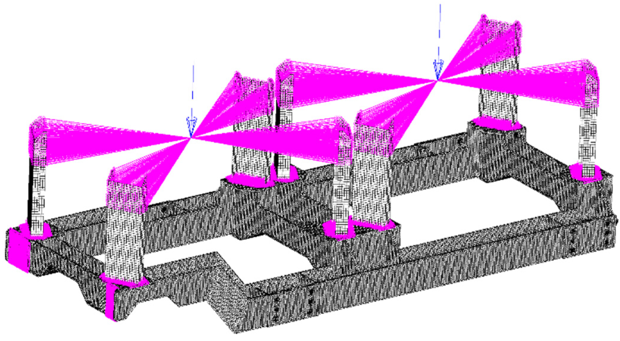
2.2.3. Boundary Conditions
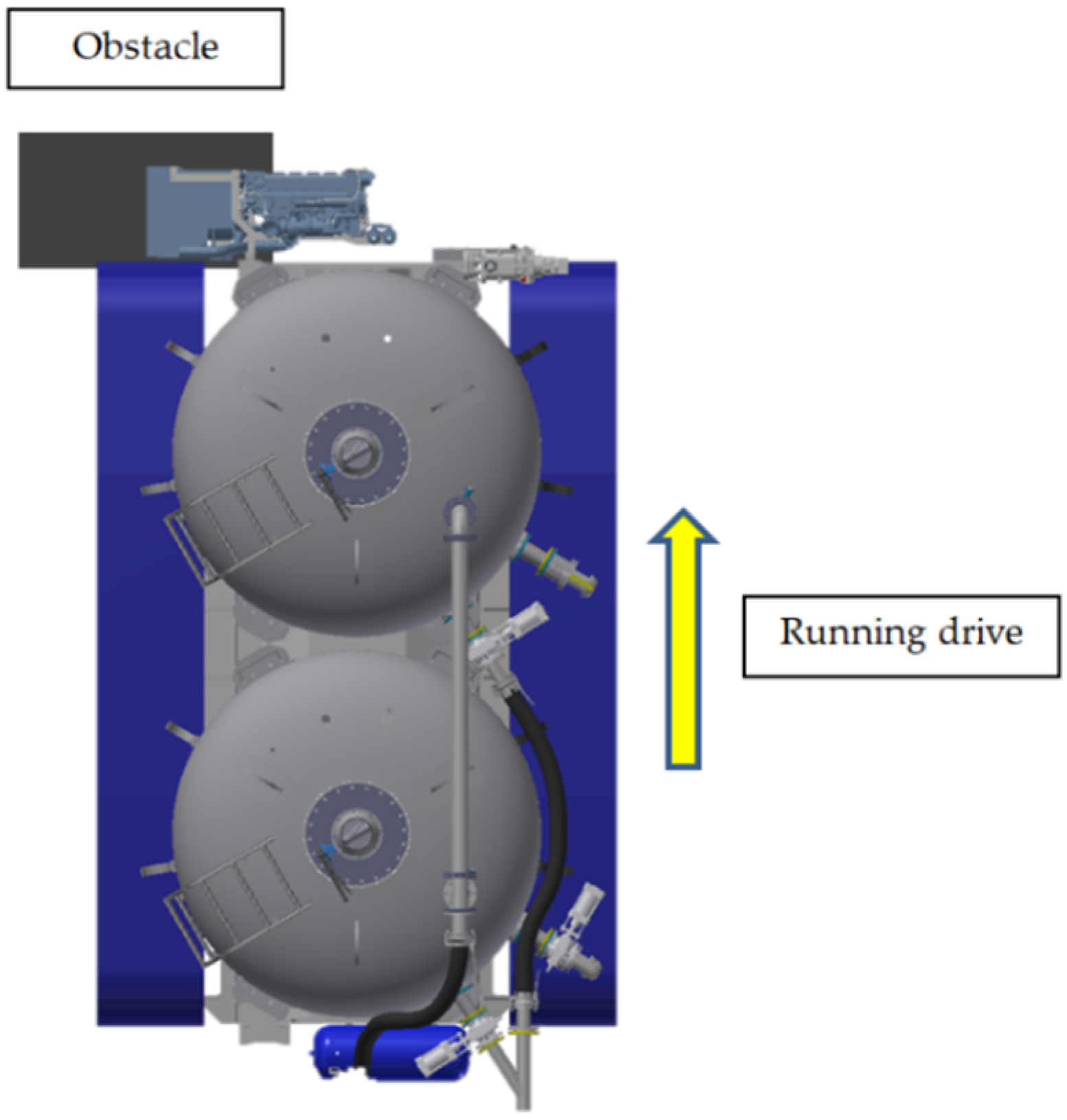
- Case 1—blocking of the left track while the right track drives on. The blocking may occur when old foundations have not been removed from the working platform. Such an obstacle is rigid and will stop the machine. This concerns the criterial state in which the vehicle hits (at a low speed) a non-deformable obstacle on the left side and the drive is activated on the right side. The assumed highest tractive force results from the achieved torque, while not exceeding the permissible values specified by the manufacturer of the drive sprocket (Figure 5).
- Case 2—drive over a convex unevenness such as a hose for pneumatic transport of cement under working pressure. The first track roller is supported on the left side and the penultimate one on the right side. Due to the fact that the vehicle is asymmetrically loaded, it was necessary to carry out a few preliminary numerical calculations in order to find the equilibrium point and select the correct roller that was fixed (Figure 6).
- Case 3—a set of fixations similar to Case 2; however, due to the asymmetrical location of the center of gravity, the first roller on the right and the last roller on the left were supported.
3. Results
4. Discussion and Conclusions
Author Contributions
Funding
Institutional Review Board Statement
Informed Consent Statement
Data Availability Statement
Acknowledgments
Conflicts of Interest
References
- Jendrysik, K.; Rybak, J. Analysis of numerical model parameters for dry-mixed soil-cement composite with high content of organic matter. IOP Conf. Ser. Mater. Sci. Eng. 2020, 869, 052007. [Google Scholar] [CrossRef]
- Jendrysik, K.; Jończyk, M.; Kanty, P. Mass stabilization as a modern method of substrate strengthening. Mater. Today Proc. 2021, 38, 2068–2072. [Google Scholar] [CrossRef]
- Varius Authors Including BRE. Design Guide for Soft Soil Stabilization. EuroSoilStab: Development of Design and Construction Methods to Stabilise Soft Organic Soils; BRE Press: Bracknell, UK, 2002. [Google Scholar]
- Directive 2006/42/EC of the European Parliament and of the Council of May 2006 on Machinery and Amending Directive 95/16/EC. Available online: https://eur-lex.europa.eu/legal-content/EN/TXT/?uri=celex%3A32006L0042 (accessed on 20 February 2021).
- PN-EN 16228-1:2014-07; Drilling and Foundation Equipment—Safety—Part 1: Common Requirements. Polish Committee for Standardization: Warsaw, Poland, 2014.
- PN-EN 16228-6:2014-07; Drilling and Foundation Equipment—Safety—Part 6: Jetting, Grouting and Injection Equipment. Polish Committee for Standardization: Warsaw, Poland, 2014.
- EFFC/DFI. EFFC/DFI Guide to Working Platforms 1st Edition January 2020. Available online: https://www.effc.org/content/uploads/2020/07/EFFC-DFI_Guide_For_Working_Platforms_July2020_Edition_1_LowRes.pdf (accessed on 18 October 2021).
- BRE. Working Platforms for Tracked Plant: Good Practice Guide to the Design, Installation, Maintenance and Repair of Ground-Supported Working Platforms. Available online: https://www.brebookshop.com/samples/146444.pdf (accessed on 18 October 2021).
- TWf. Working Platforms Design of Granular Working Platforms for Construction Plant A Guide to Good Practice. Available online: https://www.twforum.org.uk/HigherLogic/System/DownloadDocumentFile.ashx?DocumentFileKey=f74318ff-716b-79a3-f483-77f77a584e05&forceDialog=0 (accessed on 18 October 2021).
- Urbanski, A.; Richter, M. Stability analysis of drilling rigs moving on a weak subsoil. Selected case studies. Arch. Civ. Eng. 2020, 66, 303–319. [Google Scholar] [CrossRef]
- Urbanski, A.; Richter, M. Stability analysis of heavy machinery moving on weak subsoil. Analytical solution. Eng. Struct. 2021, 241, 112152. [Google Scholar] [CrossRef]
- Bunieski, S.; Quandalle, B. A Practical Example of Data Exchange and Expert System Applied to Ground Improvement Works. In Proceedings of the 3rd International Conference on Information Technology in Geo-Engineering, Guimarães, Portugal, 29 September–2 October 2019. [Google Scholar]
- Patran Complete FEA Modeling Solution. Available online: https://www.mscsoftware.com/product/patran (accessed on 6 October 2021).
- Zienkiewicz, O.C.; Taylor, R.L.; Zhu, J.Z. The Finite Element Method: Its Basis and Fundamentals, 7th ed.; Butterworth-Heinemann: Oxford, UK, 2013; ISBN 9781856176330. [Google Scholar]
- MSC Nastran Multidisciplinary Structural Analysis. Available online: https://www.mscsoftware.com/product/msc-nastran (accessed on 6 October 2021).
- Kalita, M.; Tokarczyk, J. Designing and virtual prototyping of the structures protecting the mining machines operators. Min. Mach. 2019, 1, 3–11. [Google Scholar] [CrossRef]
- Alliez, P.; Cohen-Steiner, D.; Yvinec, M.; Desbrun, M. Variational Tetrahedral Meshing. ACM Trans. Graph. 2005, 24, 617–625. [Google Scholar] [CrossRef] [Green Version]
- Ramos, A.; Simões, J.A. Tetrahedral versus hexahedral finite elements in numerical modelling of the proximal femur. Med. Eng. Phys. 2006, 28, 916–924. [Google Scholar] [CrossRef] [PubMed]
- Tadepalli, S.C.; Erdemir, A.; Cavanagh, P.R. Comparison of hexahedral and tetrahedral elements in finite element analysis of the foot and footwear. J. Biomech. 2011, 44, 2337–2343. [Google Scholar] [CrossRef] [PubMed]
- Rolek, J.; Utrata, G. Optimisation of the FE Model Based on the No-Load Test Measurement for Estimating Electromagnetic Parameters of an Induction Motor Equivalent Circuit Including the Rotor Deep-Bar Effect. Energies 2021, 14, 7562. [Google Scholar] [CrossRef]
- Gajewski, T.; Garbowski, T.; Staszak, N.; Kuca, M. Crushing of Double-Walled Corrugated Board and Its Influence on the Load Capacity of Various Boxes. Energies 2021, 14, 4321. [Google Scholar] [CrossRef]
- Chang, S.; Jeon, B.; Kwag, S.; Hahm, D.; Eem, S. Seismic Performance of Piping Systems of Isolated Nuclear Power Plants Determined by Numerical Considerations. Energies 2021, 14, 4028. [Google Scholar] [CrossRef]


| Number of Load Case | Displacements | Reduced Stresses |
|---|---|---|
| 1 | 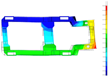 | 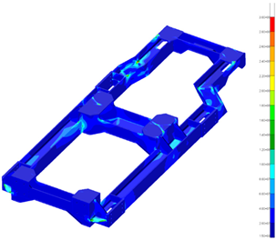 |
| Maximum value of displacements: 5.58 mm | Maximum value of reduced stresses: ~300 MPa | |
| 2 |  |  |
| Maximum value of displacements: 5.40 mm | Maximum value of reduced stresses: ~200 MPa | |
| 3 | 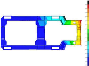 | 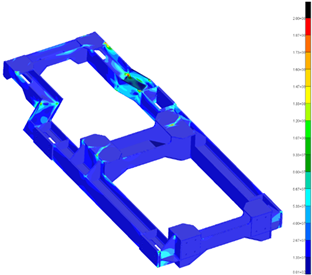 |
| Maximum value of displacements: 5.53 mm | Maximum value of reduced stresses: ~200 MPa |
| Number of Load Case | Maximum Principal Stress | Iso-Surfaces |
|---|---|---|
| 1 |  | 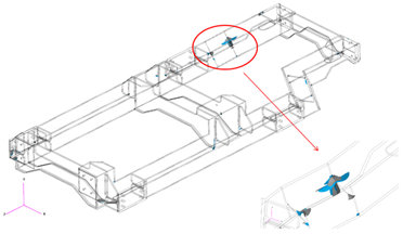 |
| Maximum value of principal stress: 300 MPa | Iso-surface of maximum stresses equal to 100 MPa | |
| 2 | 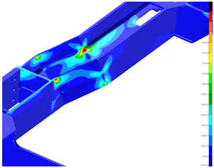 |  |
| Maximum value of principal stress: ~200 MPa | Iso-surface of maximum stresses equal to 100 MPa | |
| 3 | 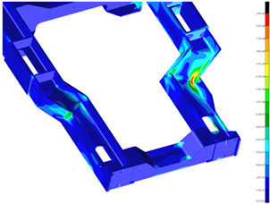 |  |
| Maximum value of principal stress: ~200 MPa | Iso-surface of maximum stresses equal to 100 MPa |
Publisher’s Note: MDPI stays neutral with regard to jurisdictional claims in published maps and institutional affiliations. |
© 2022 by the authors. Licensee MDPI, Basel, Switzerland. This article is an open access article distributed under the terms and conditions of the Creative Commons Attribution (CC BY) license (https://creativecommons.org/licenses/by/4.0/).
Share and Cite
Nieśpiałowski, K.; Tokarczyk, J.; Bartoszek, S.; Kanty, P.; Kurek, N.; Dymarek, A.; Dzitkowski, T. Virtual Prototyping of the Cement Transporter Including Strength Criterion Based on Geotechnical Boundary Conditions. Energies 2022, 15, 1742. https://doi.org/10.3390/en15051742
Nieśpiałowski K, Tokarczyk J, Bartoszek S, Kanty P, Kurek N, Dymarek A, Dzitkowski T. Virtual Prototyping of the Cement Transporter Including Strength Criterion Based on Geotechnical Boundary Conditions. Energies. 2022; 15(5):1742. https://doi.org/10.3390/en15051742
Chicago/Turabian StyleNieśpiałowski, Krzysztof, Jarosław Tokarczyk, Sławomir Bartoszek, Piotr Kanty, Norbert Kurek, Andrzej Dymarek, and Tomasz Dzitkowski. 2022. "Virtual Prototyping of the Cement Transporter Including Strength Criterion Based on Geotechnical Boundary Conditions" Energies 15, no. 5: 1742. https://doi.org/10.3390/en15051742
APA StyleNieśpiałowski, K., Tokarczyk, J., Bartoszek, S., Kanty, P., Kurek, N., Dymarek, A., & Dzitkowski, T. (2022). Virtual Prototyping of the Cement Transporter Including Strength Criterion Based on Geotechnical Boundary Conditions. Energies, 15(5), 1742. https://doi.org/10.3390/en15051742