Article

Correction Mechanism for Balancing Driving Torques in an Opencast Mining Stacker with an Induction Motor and Converter Drive System

by
Mariusz Jabłoński
* and
Piotr Borkowski
Department of Electrical Apparatus, Faculty of Electrical, Electronic, Computer and Control Engineering, Lodz University of Technology, 90-537 Lodz, Poland
*
Author to whom correspondence should be addressed.
Energies 2022, 15(4), 1282; https://doi.org/10.3390/en15041282
Submission received: 1 December 2021 / Revised: 26 January 2022 / Accepted: 3 February 2022 / Published: 10 February 2022
(This article belongs to the Special Issue The KOMTECH-IMTech 2021 Mining Technologies Future)

Abstract

:
This article describes a correction mechanism for balancing torques in moving drives. The steering system is controlled by a programable logic controller (PLC), a field-oriented control (FOC) algorithm in the drive inverter system, Process Fieldbus (PROFIBUS), and a Decentralized Peripherals (DP) network. The mechanism was applied in an opencast mining stacker with an induction motor and converter drive system. The mechanism was realized using SIMOLINK (Siemens Motion Link, SL) via fiber optic cables. Motor torque correction was applied in each electrical drive of the stacker machine. The main results presented in this paper were obtained directly from the machine. Selected digital control problems related to open mining stackers are discussed.

1. Introduction

Modern automated drive systems, in which the induction motors are powered by converter systems, have gradually displaced DC motors in most applications [1,2]. The majority of engineering machines are now equipped with inverter drive systems containing induction AC motors. The main advantages of using these motors in modern drive systems are simplicity of design, lower cost, and high reliability. Regulated electric drives using alternating current squirrel-cage motors are still the subject of intensive experimental research in both scientific and industrial centers. The most modern drive systems are controlled with the help of digital signal processors (DSP) and modern steering algorithms [3,4]. In the chosen open mining machine, an analog control technique was replaced with a digital control system, based on a PLC controller, industrial communication networks (PROFIBUS, SIMOLINK), and inverter drive systems (Siemens SIMOVERT MasterDrives Vector Control) [5]. The main goals were to improve the working stability and maneuverability of the construction, to extend the service life and exploitation time. We also aimed to improve the safety and controllability of the machine. The machine belongs to a group of the self-propelled stackers used in global opencast mining [6]. The technical and technological parameters of the stacker, its scope of work, and details of its performance, as well as assessments its safety level, stability, and operationality, have been discussed in numerous publications e.g., [7,8].

2. Materials and Methods

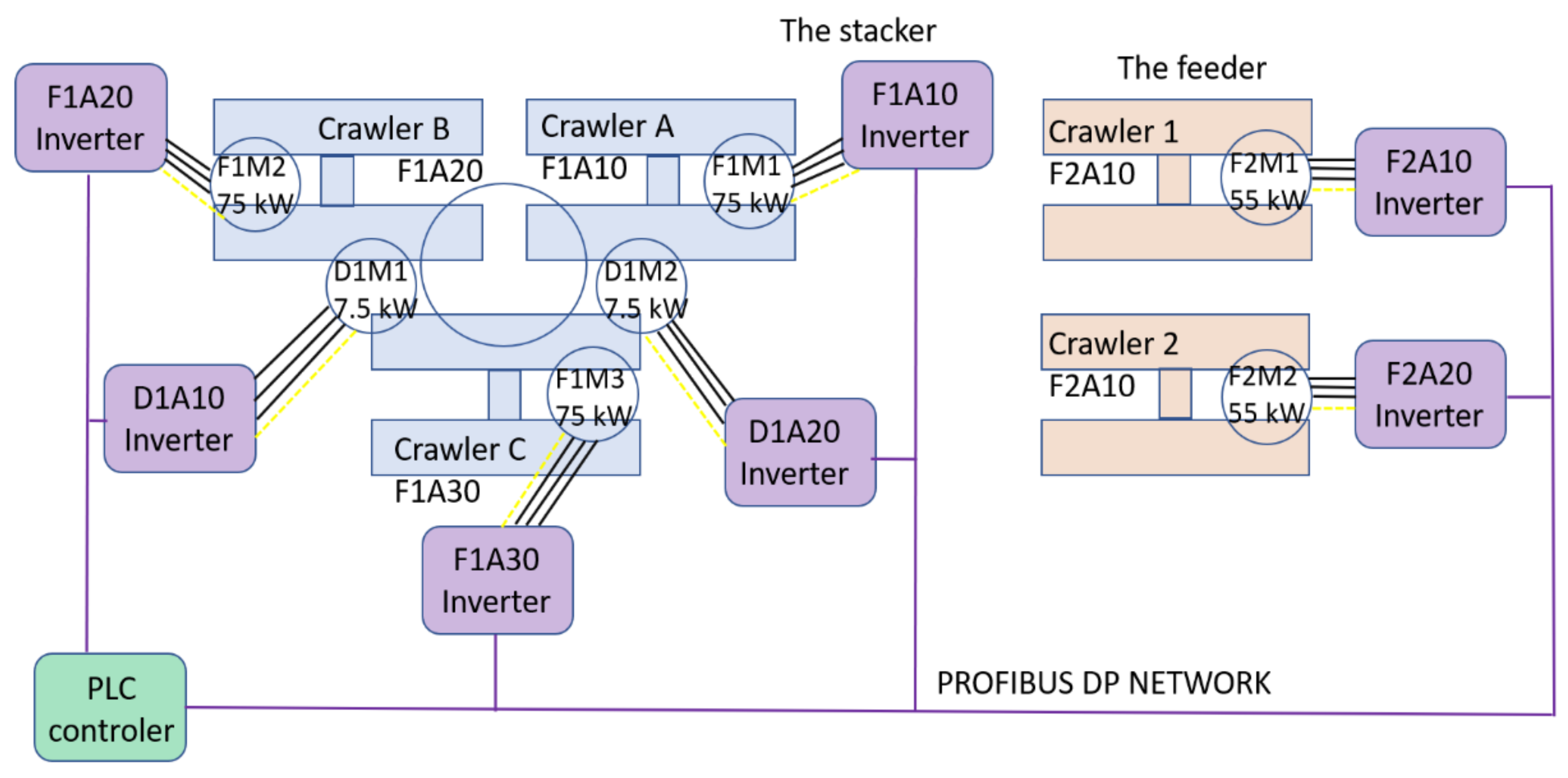
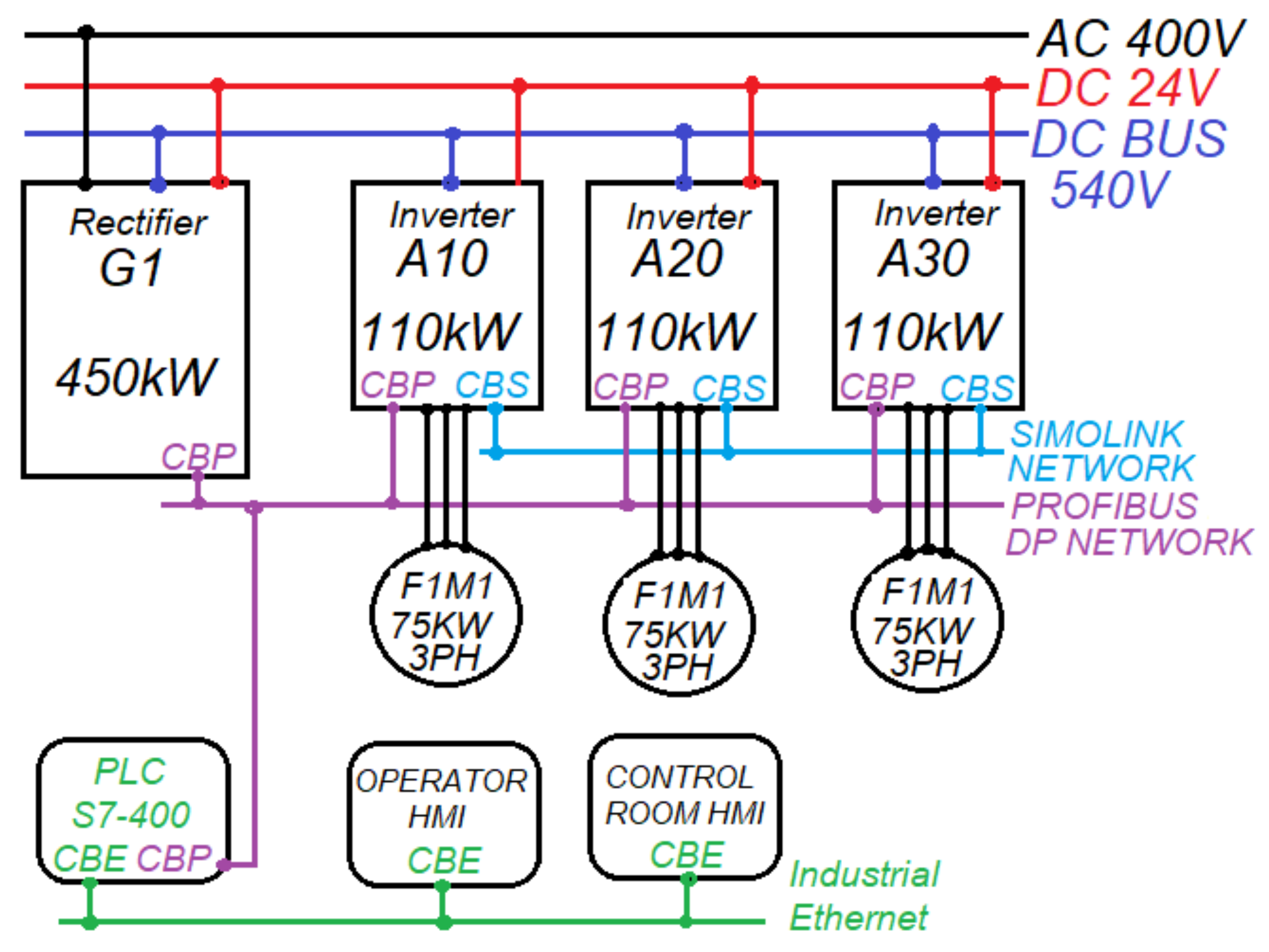
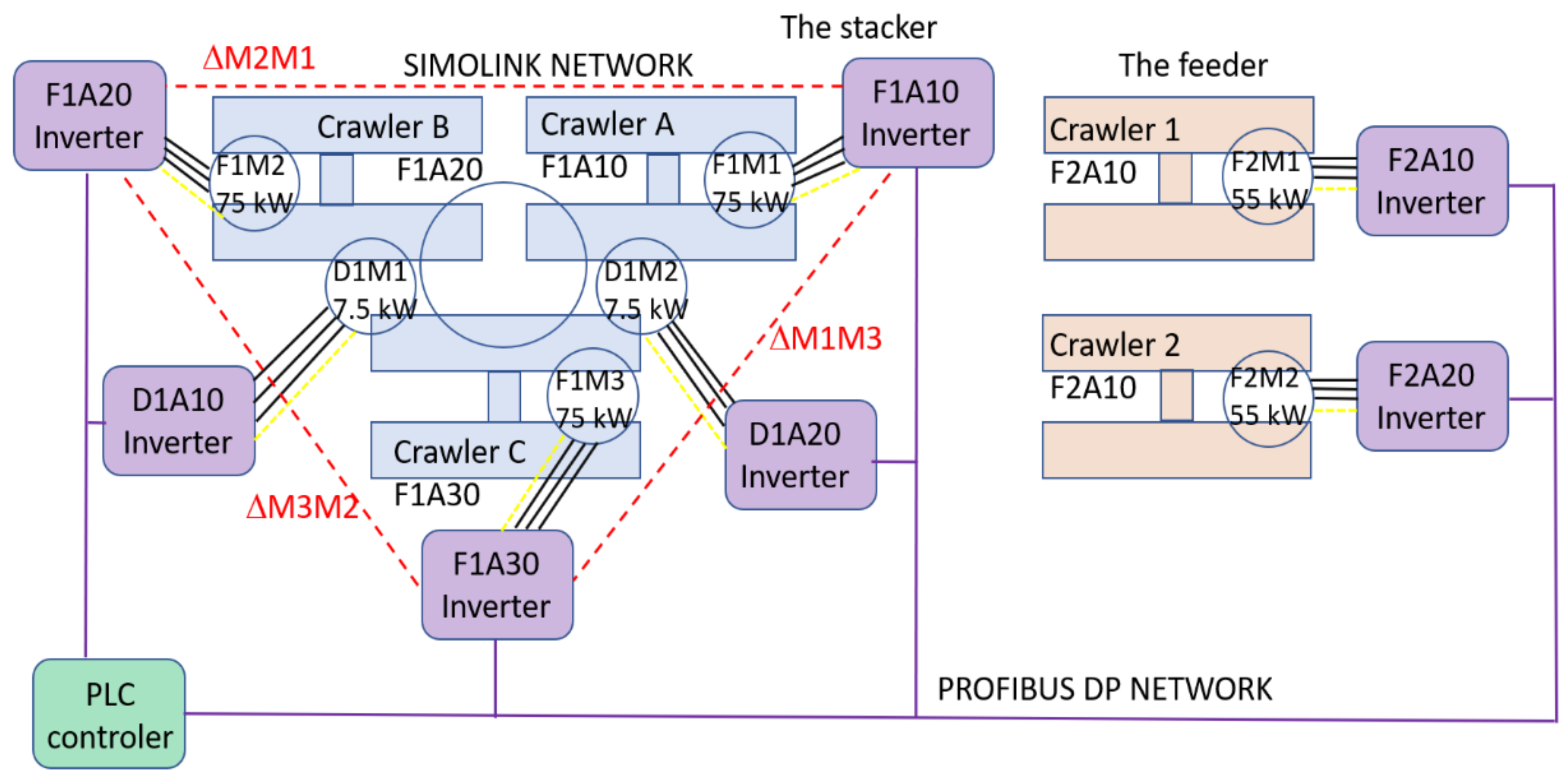
2.1. Structure of the Control System

Figure 1 presents a block diagram of the drive system solutions used in the stacker machine. The drive system of the stacker consists of three electromechanical drives with a common rectifier. Isolated gate bipolar transistor (IGBT) inverters and three AC induction motors are used for the diving part, and two electromechanical drives with two IGBT inverters and two AC induction motors are used for the rotation part. The part of the drive system for the feeder consists of two electromechanical drives with a common rectifier, two IGBT inverters, and two AC induction motors. The control part for the feeder was not the main object of our investigations and implementations.
Three inverters (F1A10, F1A20, F1A30) are used for the control stacker induction motors (F1M1, F1M2, F1M3) with nominal power PN = 75 kW. To tune the stacker, we use two inverters (D1A10, D1A20) and two induction motors (D1M1, D1M2) with nominal power PN = 7.5 kW. For the feeder, we have two inverters (F2A10, F2A20) which control the induction motors (F2M1, F2M2) with nominal power PN = 55 kW. All of the inverters use the FOC method with a closed loop control algorithm for motor control [9,10,11].
Figure 2 presents the control system of the stacker which consists of the main PLC controller, inverters, induction AC motors with encoders, object sensors, and industrial networks (Ethernet, Profibus DP, Simolink). The main PLC controller counts the main control program and sends all necessary information to the electrical drives for processing by the control algorithms [12,13]. The algorithms enable very precise regulation of the rotation speed and the driving torque in the machine motors. The application based on the space vector motor description requires knowing the parameters of the equivalent induction motor scheme [14].
The development of digital electronics and energy electronics has enabled the implementation of the latest methods of parameter identification. Drives give us completely new possibilities for immediate analysis. The values of parameters and dynamic states of the whole control system, with the investigated induction motors cooperating with the inverter drive systems, can be immediately measured by the electrical drive tool [4,5]. This is the result of a very complicated control structure. There are many possibilities for programming drives and solutions implemented in drive software require detailed parametrization. Built-in procedures for setting all parameters are used according to the data and calculated values. The described solution was implemented in 2011, as a whole modernized control system with AC drives in a mining stacker machine. The machine continues to operate without any serious faults.

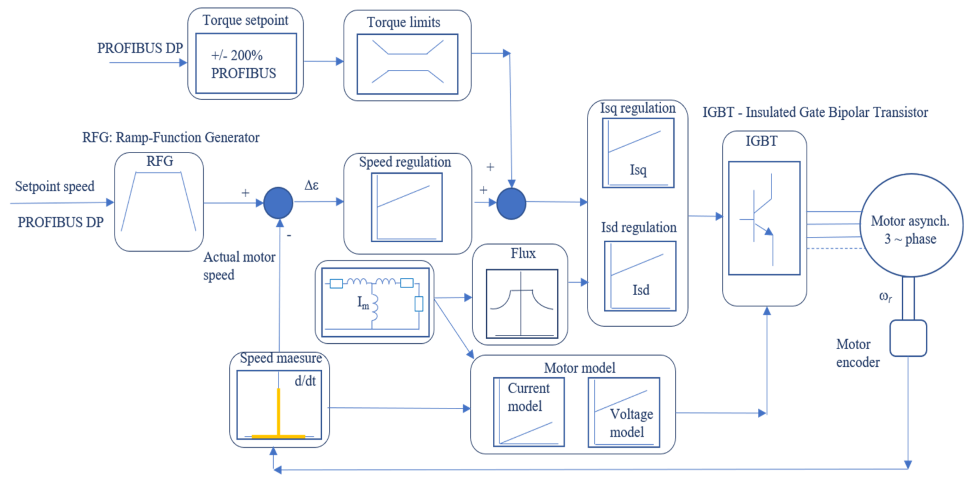
2.2. Control Algorithm for Electrical Inverter Drives

Control algorithms for drive systems with induction motors based on the FOC method have been implemented widely. The principle relies on determining the stator current components of the motor and the whole equivalent motor schema [15,16]. Additionally, it is necessary to measure or evaluate the angular position of the coupled flux vector in the machine. Information is required about the status of variables and values inaccessible to measurement, such as the flux in the rotor of the induction motor. In the practical realization of the steering or control algorithms, vector control captures the dynamic states of the whole driving system. Control signals and signals from the closed-loop part can be improved by choosing shorter times for computational cycles (Figure 3). In the main channel, we have a set point value, the Ramp-function generator (RFG) block, a proportional integrated (PI) speed regulator, torque and power limits, and the stator current components (Isd, Isq) for PI regulation, where Isd is responsible for the flux and the Isq is responsible for the torque. The motor model is very important. The ramp-function generator block (RFG) is a default located in the setpoint channel of the chosen control algorithm. It is always switched on. The RFG block limits in the setpoint channel the rate of the speed setpoint changes. As a consequence, the controlled motor accelerates and brakes more softly, for times defined by a functional parameter. This reduces the stress on the mechanical system of the driven machine. The ramp-function generator is not active if the technology controller in the inverter specifies the speed setpoint. It is possible to select between two different ramp-function generator types: an extended ramp-function generator or a basic ramp-function generator. The extended ramp-function generator limits acceleration and jerk, but the basic ramp-function generator limits acceleration, without changing the rate of acceleration [17].
This control system uses two equivalent models of induction motor: the current motor model and the voltage motor model (EMF). The current model acts from start to about 10% (default) of the setpoint value in closed-loop operation. In open-loop operation the current setpoint is used as the linear setpoint value. However, above 10% the EMF (voltage) model is used. Vector control has been found to be preferable, due to improved control characteristics—e.g., acceleration along the current limit and also lower risk of stalling [18]. An equivalent motor model with constant parameters was developed in direct studies of an induction machine. In the dynamic states, registered on site, we found that its behavior was similar to the response of a real motor, despite limitations of the model such as the omission of hysteresis, acceptance of permanent saturation of the magnetic circuit, and omission of current pushing out in the wires of windings for the motor [19]. Depending on whether the motor rotational speed is measured with an encoder or estimated from the current measurement system, starting waveforms in the control algorithm will also be quite different (Figure 4 and Figure 5). For the system without speed coupling (Figure 4), there were very large delays in establishing the transient processes of the electromagnetic state in the motor. This can be seen very clearly in Figure 4, for example during the start-up process in the part of the feeder for the stacker machine. It is also possible to examine the time curves obtained from the converter (e.g., output current, motor torque, steering error signal, speed of the motor).
The developed mechanism of control is applied in every case where the quality of control influences the quality of the technological process. The previously described state change for the equivalent motor model is clearly visible in the brown circuit schema in Figure 4. The waveforms have been included to emphasize the essence of the issues that should be taken into account in this type of work, where experiments are made directly on real objects. The results are a pure immediately real implementation of the developed solutions. All the performed works concern an actual machine, which is over 150 m long, over 40 m high, and which weighs nearly 900 tons [11]. All regulatory works performed on such an industrial facility must first be agreed with the designer, computationally verified, simulated and pre-tested in laboratories, and implemented with great care. Any damage to the mechanical part could be dangerous and disable the machine for many weeks [20].
All curves (marked with numbers from 1 to 8) given in Figure 4 are on the same percentage scale. The value of the Isd (No. 7) current component, defined in the inverter system parameters, has a decisive influence on the shaping and duration of transient states in the start-up process. The measurement time for the induction motor with electrical power of 55 kW with three pole pairs is about Δt = 2197 ms. This is quite a long time between the operator switching on the start signal and the machine starting. The system uses more than 50% of the time needed to start the process in the RFG block of the inverter (No. 2 red curve). This problem affects any application for machines controlled with the aid of an inverter system with an AC induction motor. The transient states of the start-up process in inverters with induction AC motors have been widely tested and described [1,2,3,4].
Both Isd and Isq current components in the FOC algorithm are regulated in PI blocks with the possibility for parameterization of the control settings. The values of the settings for the regulation are also important and have an influence on the dynamic states of the control machine. As a result, each switch of the power section in the inverter directly dependents on the electromagnetic construction and the control parameters in the inverters for the controlled motor. The switches are determined from the calculations of the stator flux and motor torque. For better control, such as in the driving part of stacker drives, it is necessary to measure the actual speed of the motor using a tachometric generator or encoder to evaluate the angular position of the coupled flux vector in the machine. Information is required about the status of variables inaccessible to measurement. The analyzed and expected start-up delays will be much shorter than the expected start start-up delays [21].

2.3. Basic Equation for Motor and Drive Control

To describe the dynamic states of an induction machine, a system of differential equations is formulated that constitute a mathematical model [14]. When establishing these equations, a number of simplifying assumptions are usually made, thanks to which the induction motor can be represented as a control object with equivalent and constant parameters (resistances and inductances) [15]. This corresponds to a description of ordinary differential equations with constant coefficients [16]. The associated fluxes of the stator and rotor windings depend on the currents in the windings and the self and mutual inductances. The vector-matrix equations constitute the complete system of voltage and flux-current equations of a three-phase AC induction motor in the natural coordinate system. Additionally, a formula for the electromagnetic torque of the motor is used to derive the equations of the simulation model [17]: Transforming the equations into any rectangular coordinate system rotating with the angular speed ωk and also with the instantaneous values, the following is obtained, [14,15,16,17,18]:
u sk = i sk R s + d Ψ sk dt + j ω k Ψ sk u rk = i rk R r + d Ψ rk dt + j ω k ω Ψ rk Ψ sk = i sk L s + i rk L m Ψ rk = i sk L m + i rk L r J p d ω dt = 3 2 p Ψ s i s M o
where: ωk—electric angular speed of the coordinate system; ω—angular electric speed of the rotor, Lm—mutual inductance between the stator and rotor windings, reduced to the stator circuit; Lr—self inductances depending on the scattering factor stator and rotor windings; us—stator voltages; ur—the rotor voltages; is—stator currents, ir—rotor currents; Rs—stator winding resistance; Rr—rotor winding resistance, reduced to the stator circuit; Ψs—associated stator flux; Ψr—associated rotor fluxes; Mo—load motor torque; p—pole pair number; J—moment of inertia.
The relationships between the power supply conditions, voltage, and current waveforms of the individual phases of the stator and rotor windings, as well as the magnetic fluxes associated with these windings, and the torque developed by the motor, are described by the above system of equations. The space vector of the stator current Is rotates with respect to the fixed stator at the speed ωs, similarly to the voltage Us and flux vectors. On the other hand, the space vectors of the rotor current Ir, the rotor flux, rotate in relation to the rotor at the speed ωr. For this reason, it is profitable to define the stator and rotor vectors in a common coordinate system k, which can be associated with the rotor (rotating with electric angular speed ω), stationary (associated with the stator), or rotating at a certain constant angular speed ωk ≠ ω. The electromagnetic torque was determined by substituting the flux associated and the stator current expressed by its components. Finally, after the transformations, we obtain the formula for the electromagnetic torque of the motor, depending on the individual components for axes d and q:
M e = 3 2 p L m L r Ψ rd i sq Ψ rq i sd
The full equation of the motor dynamics is described by Equations (3) and (4) [15,16,21,22]:
M d = M e     M o
d ω dt = p J 3 2 p L m L r Ψ rd i sq Ψ rq i sd M o
where: Me—electromagnetic motor torque; Md—dynamic motor torque; Mo—load motor torque; Ψrd—actual component of rotor fluxes in d axe; Ψrq—actual component of rotor fluxes in the q axis; isd—actual component of stator current in the d axis; isq—actual component of the stator current in the q axis; p—pole pair number; J—moment of inertia.
The dependencies above constitute a set of equations describing an induction motor in dynamic states. They were the basis for changing the control algorithms and building a simulation model of the induction motor in the coordinate system (d, q). In the mathematical model of the motor, the variables are the components of the spatial vector of the stator current (isd, isq), the components of the rotor flux vector (Ψrd, Ψrq), and the rotational mechanical speed ωm. The excitations are components of the spatial vector of the stator voltages (usd, usq) and components of the spatial vector of the rotor voltages (urd, urq). The whole system is considered in a rectangular coordinate system, rotating at the angular speed ωk. The amplitude of the stator current Is, the frequency of the stator voltage fs, the field-oriented components of the stator current Isd and Isq, and the relationship between the output quantities of the frequency converter, have no direct mathematical equations [21]. The slip frequency fr of the rotor, as a control variable, used in simple control methods and in the classical theory of electrical machines, is not present in the direct mathematical notation. On the other hand, the motor slip pulsation ωr can be calculated taking into account the d and q components of the stator current, according to the following equation [18,19]:
ω r = i sq t L m T r Ψ rd t
The relations between the output quantities of the frequency converter and the field-oriented components Isd and Isq can be determined when we have information about the angular position of the flux vector [12]. The above relationships constitute a complete set of equations describing an induction motor in dynamic states and were the basis for building an equivalent model of the motor in FOC [5].

3. Results

3.1. Investigation of Inverter Drive Systems in an Opencast Mining Stacker

In use, the drives work under frequently changing electromechanical conditions, depending on changing loads and different control supply voltages [2,3]. Higher technical requirements are put on these systems in terms of dynamics and efficiency [1,7]. In the design stage, it is therefore necessary to take into account the dynamic characteristics. Models and simulations of the transient electromagnetic processes are useful tools [4,15]. When the system is working with the chosen control algorithms (scalar or vector) and manually set parameters in the inverter control system, special attention should be paid to avoid dangerous settings (e.g., frequencies, torques, electric power) that may cause the whole mechanical structure to vibrate, possibly leading to resonance [8,13,20]. All curves (marked with numbers from 1 to 8) in Figure 5 are on the same percentage scale related to the defined inverter parameter system, the rated nominal values, and the quantity values. The presented working characteristics fall into dangerous oscillations during start-up and remain with less intensity until the stacker mining machine stops. The measured actual torque oscillations (No. 6) during normal work are from −15% Mn up to 130% Mn of the nominal motor torque value Mn. The measured oscillations for motor speed are from 85% to 110% nn of the nominal speed (No. 2).
On the basis of the analyzed characteristics, it can be concluded that normal safe operation of the machine will not be possible in this state. Corrections to the control algorithm and changes in the parameter settings are necessary. Additionally, the analyzed motor had a problem with the magnetizing current component (No. 7 Isd). The defined value of the magnetizing current was wrong and the Isd current component was too low. The characteristic curve shows how the system is trying to react by regulating both the Isd current component (No. 7) and the Isq component (No. 8). Generally, the electromagnetic state in the motor should be stable and only Isq should be controlled and changed. Of course, the motor flux corresponds to Isd and should be nearly constant. Because it is not, we see additional effects of improper regulation and increasing torque oscillation. The Isq current component, like the torque component, coincides with the torque curve, reacting to changes in the set value and the actual value in the PI regulator of the current Isq component, which is incorrectly regulated. A breakthrough is presented as an example illustrating the influence of the incorrect settings on the control parameters in the inverter, finally resulting in vibrations throughout the whole machine—Figure 5.
The problem of resonance vibrations in opencast mining machines has been the subject of many studies [2,21]. According to the commonly known formula, we can define the general external excitation [8]:
F (t) = mx (t) + cx (t) + kx (t)
where: F (t)—external excitation; m—mass; c—damping; k—stiffness.
Equation (6) is provided to indicate which components appear on the object as excitations inducing vibrations. Analysis indicated that these negative effects occur due to the frequency change in the control system of the selected machine drive, when the control algorithm is used with wrong regulators settings. The intensity will depend on the selection of parameters and limits. There are several ways to move the system and the machine out of the resonance area [8]:
-
by changing the frequency of dumps
-
by changing the weight of the body
-
by increasing the stiffness of the body
Changing the weight of the body is in our case impossible. Increasing the stiffness of the system is also not possible and troublesome. Of course, depending on the weather, environment, and external temperatures, we could make changes in the settings of parameters influencing damping and stiffness. It would be necessary to take into account our settings and check their functional parameters within the set limits. It turns out that the simplest and most frequently used solution is a change of the excitation frequency. When we use inverter drive solutions with induction motors, we can change its functional parameters in the control algorithm settings [4]. We could use a function such as the skip frequency band in the setpoint channel. The function of skip value for the setpoint channel guarantees bypassing undesirable frequency values in front of the ramp-function generator in steady-state operation. These values will not appear in the range of the positive and negative values for the skip frequency functionality [5,10,22]. Changing the setpoint frequency value for the controlled quantity in the main setpoint channel can also be obtained by changing the basic settings of the PI regulators located in the speed control section and the stator current components. The mechanical structure of the mining machine is also a very sensitive receiver of all sources generating additional vibrations, [23]. The superimposition of these phenomena may result in undesirable disturbances of the whole construction [7,19,23]. Therefore, we limited the value of the torque correction ΔM to 10% Mn using the influence on the motor torque through the indirect channel (additional speed > torque > Isq component) and not the direct channel (Isq component) [4,5].

3.2. Correction Mechanism for the Balancing Driving Torques

Figure 6 presents the correction mechanism for the balancing driving torques in the converter drive system of the opencast mining stacker. From the inverter system and industrial communication, the PLC system receives actual torques for the induction motors used as a driving system in the stacker machine. Next, instantaneous average values are calculated for the motor torques. For the F1M1 and F1M2 motors, we have the correction value ΔM2M1, for F1M1 and F1M3 motors we have the correction value ΔM2M3, for F1M3 and F1M2 motors we have the correction value ΔM3M2.
The process of data exchange between the SIMATIC S7-400 controller and connected rectifiers, inverters, and converters is realized via a PROFIBUS DP network with a communication and operation speed of 1.5 Mbps. Cyclic communication occurs in both directions, from the PLC to the drive and from the drive to the PLC. For all inverters and rectifiers, a process parameter object (PPO) type 5 data structure was used. The structures of the sent and received process data (PZD) could be adapted for each device. The parameter data area (PKW) is not used in the implemented solution, as it is acyclic and causes unnecessary communication delays [5]. In the analyzed fragment of the network, there are 5 slaves, each of which uses 10 PZD areas, which are 16-bit. For each device, the process data structure is sent and received via DB blocks located in the Simatic S7-400 controller. When the operator gives the start signal for all inverters, after confirmation of the torque generation in the motors a signal releases the brake of the retarder. The PLC controller sends setpoints values and receives actual values with the aid of the PROFIBUS DP network in both directions: from the network Master (PLC) to the network slaves (inverters) and from the network slaves to the network master (PLC), at a rate of 1.5 Mbit/s. This communication is carried out cyclically at up to 10 ms (cycle time), which is guaranteed by the built-in mechanisms of operation of the PROFIBUS DP networks in versions V0, V1, and V2. This gives us feedback on the electrical and non-electrical quantities of the control algorithm and connected motors, which are sent directly from the inverters to the PLC and back.
The whole technological process can be visualized as electrical and non-electrical curves. Using the detailed human machine interface (HMI), the operator can set the main process values and limits. The HMI monitors the operation of the entire system, verifies current values, and acknowledges alarms. Additional screens verifying changes in the waveforms for the regulated variables have been developed. The settings and torque equalization functionality can be turned on or off and changed by the operator via the HMI. All currently measured signals from the sensors are displayed on HMI.
Using the optical fiber network SIMOLINK with a communication speed of up to 12Mb/s, the torque corrections are cyclically sent at about up to 3.2 ms (cycle time) to particular drives and finally to the electrical motors. This cyclic communication occurs in both directions (from drive to drive and vice versa). The modified system has two operating modes, selected via the PROFIBUS DP network. In each of the two modes, the inverters work independently, but depending on the function selected the following states are provided [1,6,19]:
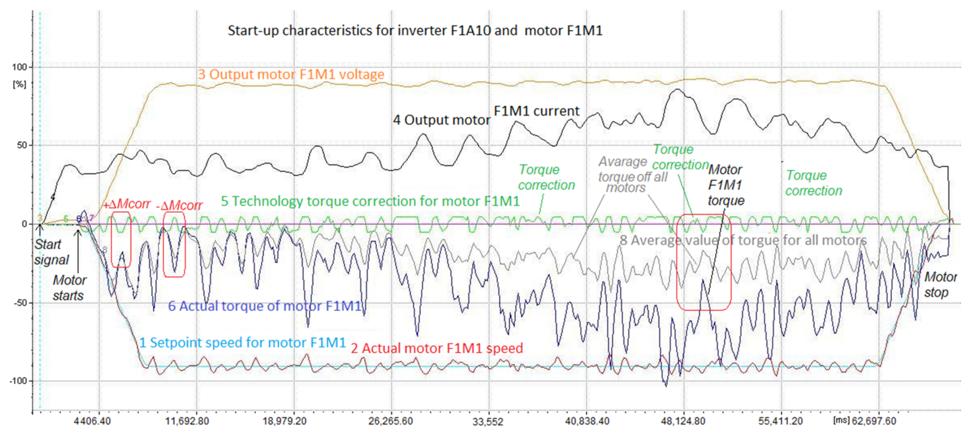
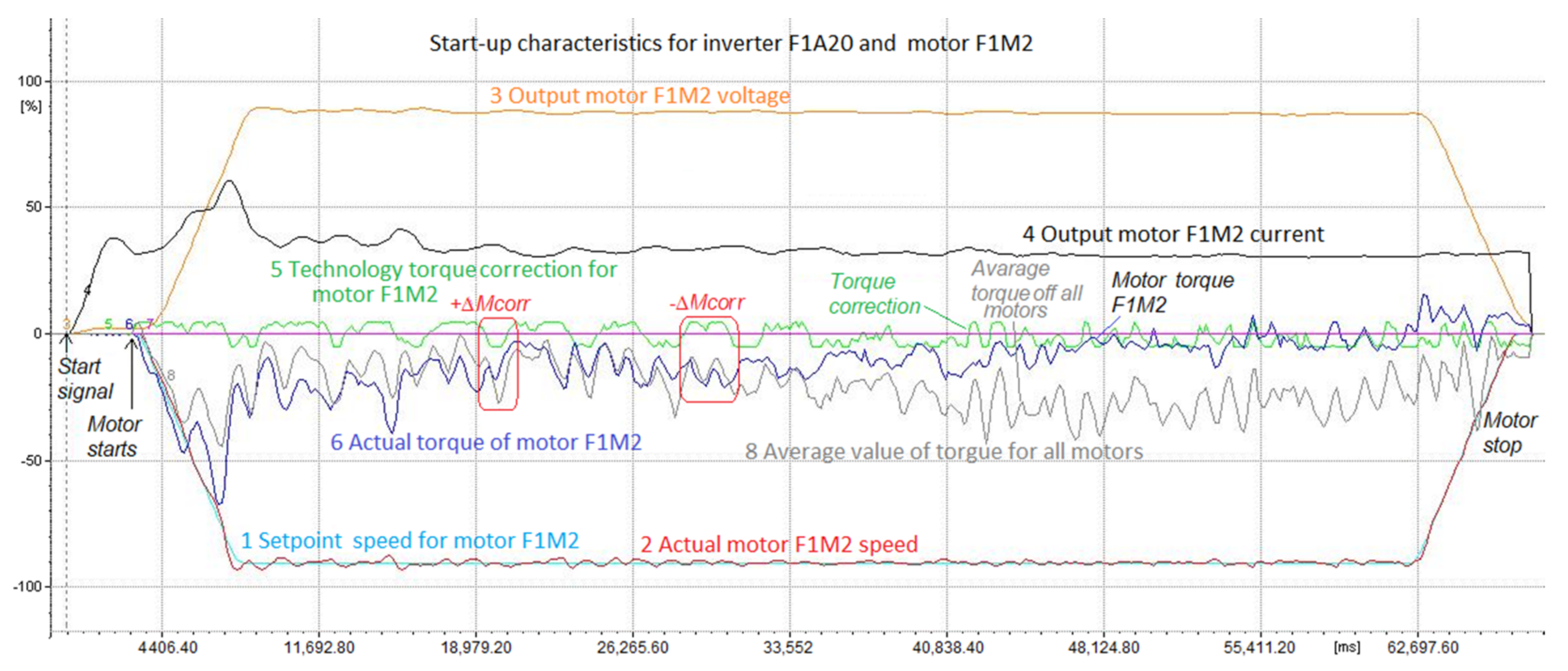
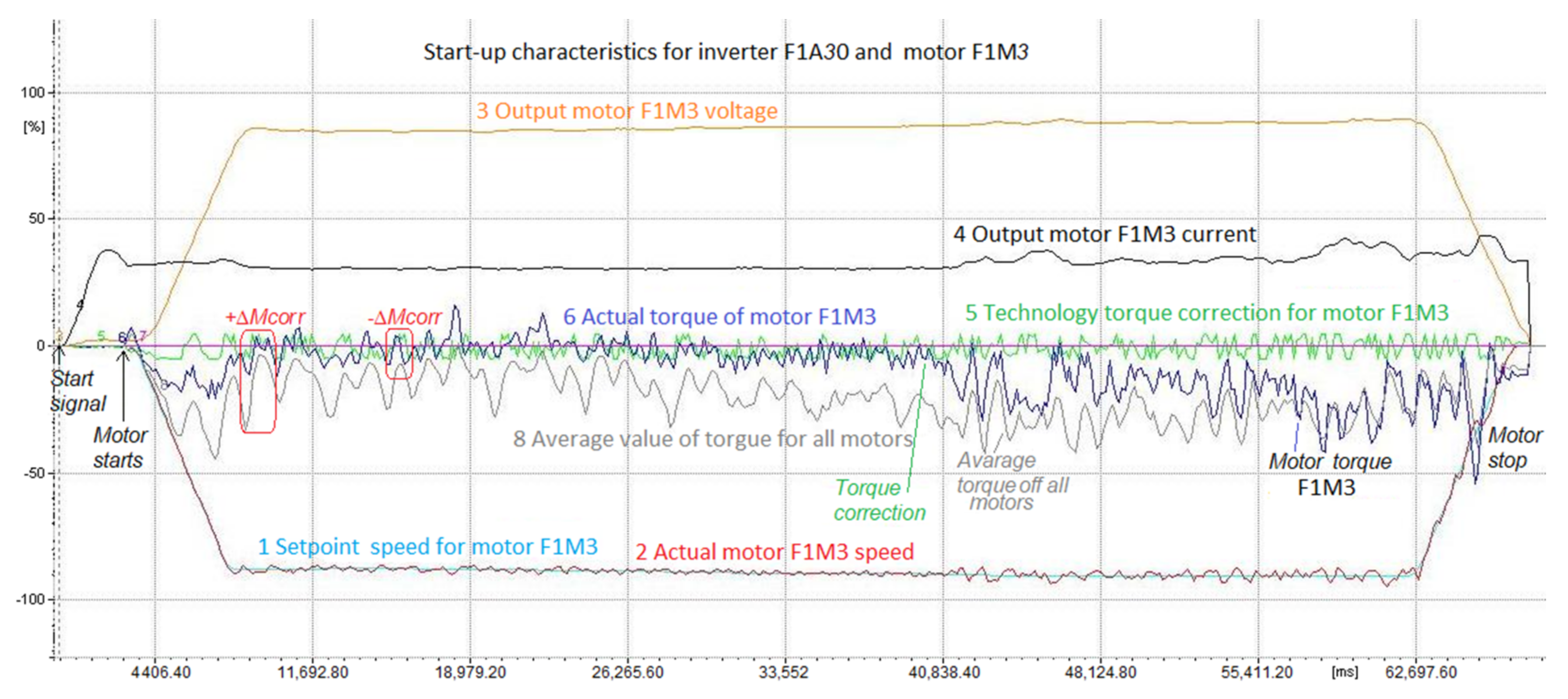
  • Speed control mode (Figure 3), where each inverter receives a set speed value from the PLC controller, resulting from the geometry of the current track alignment, and the driving speed is given by the operator.
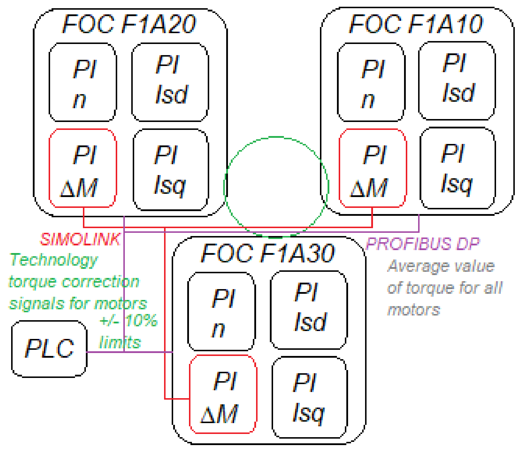
  • Speed control mode, with torque corrections (Figure 6 colored in red), where each inverter receives a set speed value from the controller, resulting from the geometry of the current track settings, and the driving speed is set by the operator. Based on the deviation of the actual drive torque from the average value of all drives, each inverter generates an appropriate correction of the set speed to equalize the torques. The amount of the correction related to the controller setpoint is set at ± 10% (empirically selected during start-up). The mean torque value for all drives was calculated, using the SIMOLINK network in the F1A10 inverter for sending process data. The average torque value from the F1A10 inverter is transferred to all other inverters via the SIMOLINK network.
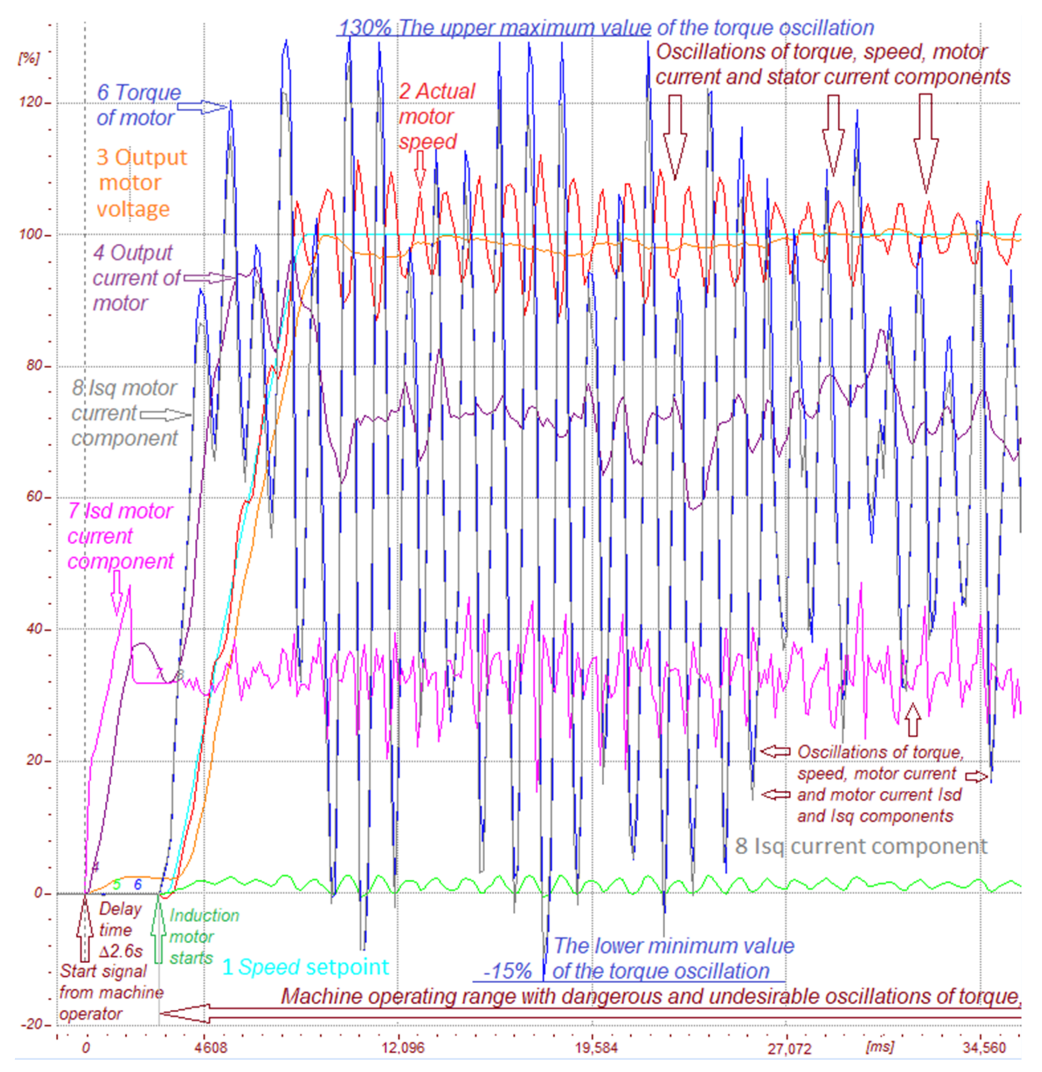
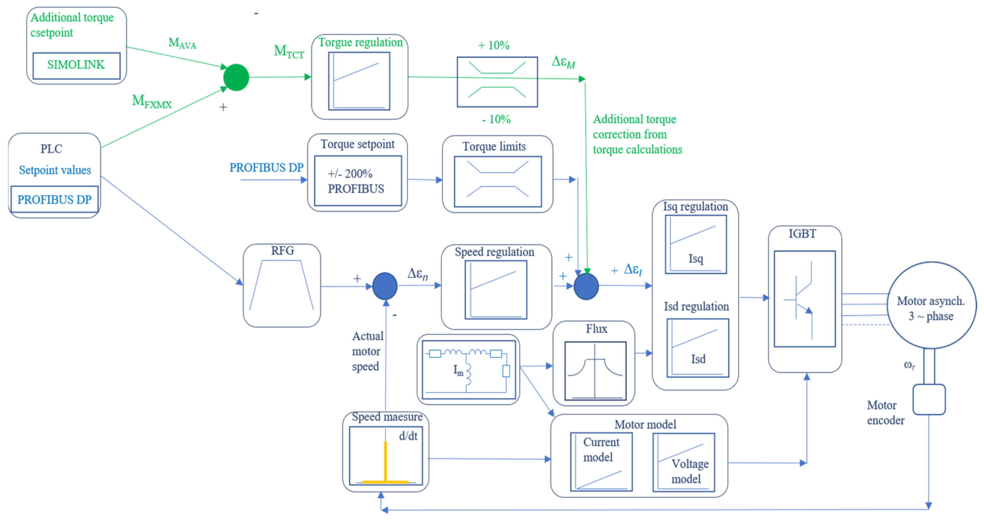
  • Torque boost mode, where by changing the torque limitations the torque boost function is additionally provided. This mode is realized by transmitting the torque limit value from the PLC to the inverter control algorithm. The torque limit values for normal and forced operation were established based on documentation and tests, then stored in the PLC (Figure 7).
The mechanism of introducing torque correction, added or subtracted from individual drives (the sign depends on the sign value of the average value), the sign/direction/value of which depends on the currently calculated average values, enables the distribution of machine loads to be changed. In the new modified solution of the control algorithm (Figure 6), we have the following dependences for torque in the drives:
MFXMX − MAVA = MTCT
where: MFXMX—one of three torques of the used motors; MAVA—average value of torque for all motors; MTCT—technology correction torque value added to the control algorithm.
The practical realization was made with aid of Siemens BICO (binector-connector) graphical technology and programed immediately in the inverter using a whole dedicated structure for free blocks and the regulator. Finally, the torque correction value MTCT was added to the control algorithm, given to the PID Technology controller input, and regulated. The regulator settings were applied empirically. As a result, a signal shown in Fig. 8 as signal No. 5 (the technology correction factor) was obtained. This is the correction signal which most strongly influenced the actual value of the motor torque. Based on experience gained over about 10 years and for safety reasons related to the regulations, the mechanism of torque correction was applied through the main channel of the set point value, which is an intermediate solution. However, it ensures greater stability of the regulation, and the introduced corrections did not adversely affect the operation of the machine structure. We add torque correction in the same way as the additional speed value:
ω r = ω SET +   ω ADD = > i sq t L m T r Ψ rd t = ω SET +   ω ADD
where: ω SET —rotor pulsation setpoint speed; ω ADD —additional rotor pulsation speed. The indicator of the selection of settings was the verification of changes in mileage, deviations, adjustment, and comfort of operating the drive machine, which was each time tested on a different surface and in a regime corresponding to real operating conditions.
All curves (marked with numbers from 1 to 8) shown in Figure 8 are on the same percentage scale, related to the rated nominal values and quantity values defined in the inverter parameter system. The measurements were repeated after several runs backwards and forwards. It is clear from Figure 8 that the F1A10 track is unevenly loaded when driving forward, because it takes over the drive of the machine. The F1A20 caterpillar behaves in the same way when driving backwards: the courses are shown later in this section.
Figure 8 shows how the torque correction mechanism acts. The torque correction is always generated to balance the unequal load. The presented breakdown is the result of several months of work in the field, during which hundreds of verification tests were performed, including monitored and supervised production after implementation. The curves are not random characteristics, but the effect of the precisely selected settings for the objects, so that machine vibrations could be avoided. For comparison, Figure 5 shows results for the same machine but without any verification and implementation measures.
All curves given in Figure 9 (marked with numbers from 1 to 8) are on the same percentage scale, related to the rated nominal values and quantities defined in the inverter parameter system.
The torque correction value was programmed as a function that can be turned on or off by the machine operator. Additionally, on the HMI panels located in the operator’s cabin and in the switching station with inverters, a visualization was developed of the curves as waveforms. This allowed us each time to observe, verify, and check the effectiveness of the implemented changes. Due to the asymmetrical structure and triangular arrangement of the caterpillars, the selection of parameter settings required a large expenditure of time and intermittent service verification. In particular, the change of seasons has a strong impact on the operation of the machine, changing the ambient temperature and the temperature of the ground.
In Figure 10 all curves (marked with numbers from 1 to 8) are given on the same percentage scale, related to the rated nominal values and quantities defined in the inverter parameter system.
Comparing the operation of the mechanism in a system of three asymmetrical tracks, it is clear that the load is also asymmetrical and is the largest for drive F1A10 and motor F1 M1. The mechanism introduced for the correction of stresses coming from the driving torques of the induction motors was initiated by the maintenance services of the opencast mine and together with these services was implemented and tested in the open mining pit.
Figure 11 shows a block diagram of the implemented solution. We use both PROFIBUS and the SIMOLINK network for PZD data exchange and the internal software of each inverter to program the new solution. With the aid of BICO, we programmed a new PID regulator to regulate torque correction. All values were limited to ±10% of the nominal torque value.
Based on the literature and the authors’ own research and experience, the approach to the construction of new opencast mining machines based on inverter drives with induction motors as well as the modernization of existing machines should be changed. Industry 4.0 solutions, model verification, and the construction of prototype models are needed. Mapping the most important substitute parameters in an advanced control algorithm for a controlled object, such as a dumping machine, is a very complex task. The values of the introduced parameters have a significant impact on electromechanical states, transient processes, and stability of control systems.

4. Discussion and Verification of Method Implementation

Verification tests were made in 2021, after the machine had 10 years of heavy industrial operation. During this time, the machine had continued to work properly without any major failures or downtime. Following repairs at the end of the operating time, it was necessary to make adjustments. The equivalent parameters, the correction values, and the PI settings were checked and reset (Figure 12). All curves (marked with numbers from 1 to 8) in Figure 12 are on the same percentage scale, related to the rated nominal values and the quantities defined in the inverter parameter system.
Based on experience and knowledge of the control algorithms of inverter systems, a change to the solution concerning the introduction of a cortex of moments into the control algorithm can be proposed. Instead of entering an additional value in the speed channel (adjustable), it may be entered after the speed controller in the torque channel, which will greatly speed up the swap response. In this configuration, the SIMOLINK network is eight times faster than the PROFIBUS network, so information about changes in the moment in the torque channel will appear much faster. Using the same vector control, the correction will be applied in the term directly to the stator current Isq component (torque component). The torque equation is
M d = 3 2 p L m L r Ψ rd i sq Ψ rq i sd M o + M TCT
Future plans for modifying the torque correction mechanism with immediate implementation on mining machines are shown in Figure 13. We will also verify delays arising in the control loops of control structures for industrial communication, such as those affecting feedback signals, which may cause temporary loss of stability in the control systems of mining machines. We will carry out analyses of possible failures and electromechanical damage occurring in facilities, locating the causes and verifying the operation time, especially after failures causing long downtime or the need to replace mechanical elements with new or regenerated ones after only a short period of use. The cyclical recording of drive characteristics will be investigated in digitally controlled machines and the received data will be verified. We will also verify the value of the magnetizing current introduced into the inverters control algorithms and the parameters of the equivalent diagrams of the motors. The settings of the speed and stator current regulators as well as the limits of static and dynamic settings and other functions should be adjusted, depending on the season, ambient temperatures, and weather. Full analysis of the motion characteristics in the frequency domain will also be conducted.
The solutions described in this paper were applied in 2010. The performance of the operational opencast stacker has confirmed the effectiveness of the method. An additional aim of this article has been to indicate possible opportunities for development of the method. In future work, solutions will be introduced to further improve safety and machine operating conditions (better maneuverability, torque forcing, torque correction, summer and winter settings), as well as to extend maintenance intervals.

5. Conclusions

-
The analyzed machine has a triangular drive system, which is asymmetrical. This affects the stability of the machine and the load distribution in the system.
-
The implementation of the torque balancing load mechanism improved the drive parameters of the machine.
-
Model parameters responsible for electromagnetic transient processes were improved and the settings of the regulators and limits were selected.
-
The machine is not subject to vibrations resulting from the influence of the frequency of the control system.
-
Failure to take into account the dynamic overloads when estimating the durability of a gear train may cause its premature failure.
-
Application of the objective function that lowers the maximum contact stresses and stresses at the base of the mechanical teeth of the band in the optimization process effectively increases the durability and reliability of the driveline.
-
A whole problem-oriented control algorithm could be designed using the main FOC principles and for example a fuzzy or neuron controller. It is very important to select the control settings and limits for the measured signals. The mechanism should be calculated, simulated, and tested before its practical implementation.

Author Contributions

Conceptualization, M.J. and P.B.; methodology, M.J.; software, M.J.; validation, M.J., P.B.; formal analysis, P.B.; investigation, M.J.; resources, M.J.; data curation, M.J.; writing—original draft preparation, M.J.; writing—review and editing, P.B.; visualization, M.J.; supervision, M.J.; project administration, M.J.; funding acquisition, P.B. All authors have read and agreed to the published version of the manuscript.

Funding

This research received no external funding.

Institutional Review Board Statement

Not applicable.

Informed Consent Statement

Not applicable.

Conflicts of Interest

The authors declare no conflict of interest.

References

  1. Hertel, L. Technika przekształtnikowa w napędach jazdy i obrotu na maszynach podstawowych—doświadczenia eksploatacyjne. Górnictwo Odkryw. 2008, 49, 38–41. (In Polish) [Google Scholar]
  2. Jabłoński, M.; Borkowski, P. Wymiana systemów sterowania wraz z implementacją cyfrowej falownikowej techniki napędowej w maszynach górnictwa odkrywkowego. Praca zbiorowa. Monografia. KOMTECH 2020, 1, 6–22. (In Polish) [Google Scholar]
  3. Jabłoński, M.; Borkowski, P. Industrial implementations of control algorithms for voltage inverters supplying induction motors. Arch. Electr. Eng. 2021, 70, 475–491. (In English) [Google Scholar]
  4. Jabłoński, M. The Analysis of Functional Parameters and Modification of Steering Algorithms in Vector Control Converter drive with an Induction Motor; Technical University of Łódź: Łódź, Poland, 2007. (In English) [Google Scholar]
  5. Siemens-Technical Documentation, Engineering Manual and Compendium for SIMOVERT MASTERDRIVES, Automation and Drives, Variable-Speed Drive Systems, Erlangen 1999–2012, Siemens AG (2020). (In English). Available online: https://support.industry.siemens.com/cs/attachments/109736629/vc34_kompend_f.pdf?download=true (accessed on 30 November 2021).
  6. Borczyk, Z.; Trajdos, M. Sterowanie jazdą maszyn górniczych regulacja prędkości z korekcją momentu. Górnictwo Odkrywkowe 2008, 49, 21–25. (In Polish) [Google Scholar]
  7. Hertel, L.; Nowacki, H. Algorytmy sterowania napędami na modernizowanych koparkach. Czas. Górnictwo Odkryw. 2014, 55, 39–43. (In Polish) [Google Scholar]
  8. Huss, W. Problems of Bucket-Wheel Excavators Body in Hardly-Workable Grounds in Polish Open Pit Mines. In Proceedings of the 12th International Symposium Continuous Surface Mining; Aachen, Germany, 24–27 September 2014, Niemann-Delius, C., Ed.; Lecture Notes in Production Engineering; Springer: Cham, Switzerland, 2015. (In English) [Google Scholar]
  9. Blaschke, F. Das Verfahren der Feldorientierung zur Regelung der Asynchronenmaschine. Siemens Forsch. Und Entwickl. 1972, 1, 184–193. (In German) [Google Scholar]
  10. Jabłoński, M.; Borkowski, P. Metody poprawy algorytmów sterowania systemów napędów maszyn górnictwa odkrywkowego. KOMTECH 2021, 1, 139–148. (In Polish) [Google Scholar]
  11. Wocka, N. Możliwości zaspokojenia popytu na wysokowydajne krajowe maszyny podstawowe dla przyszłych potrzeb górnictwa węgla brunatnego. Górnictwo I Geoinżynieria 2010, 4, 537–546. (In Polish) [Google Scholar]
  12. Trajdos, M.; Leśniewski, K. Zastosowanie napędów regulowanej prędkości w odkrywkowych zakładach górniczych—Zagadnienia wybrane. Górnictwo Odkryw. 2012, 53, 9–13. (In Polish) [Google Scholar]
  13. Jabłoński, M. Ekspertyza Przenośnika Samojezdnego PGOT-4500. Protokół z Wykonanych Prac Zlecenie HP/AG-W26/09; PGE KWB Turów S.A.: Bogatynia, Poland, 2021. (In Polish) [Google Scholar]
  14. Paszek, W. Dynamika Maszyn Elektrycznych Prądu Przemiennego; Helion: Gliwice, Poland, 2011. (In Polish) [Google Scholar]
  15. Kalus, M.; Skoczkowski, T. Sterowanie Napędami Asynchronicznymi I Prądu Stałego; Pracownia Komputerowa J. Skalmierskiego: Gliwice, Poland, 2003. (In Polish) [Google Scholar]
  16. Pełczewski, W.; Krynke, M. Metoda Zmiennych Stanu W Analizie Dynamiki Układów Napędowych; WNT: Warsawa, Poland, 1984. (In Polish) [Google Scholar]
  17. Tunia, H.; Kaźmierkowski, M. Automatyka Napędu Przekształtnikowego; PWN: Warszawa, Poland, 1987. (In Polish) [Google Scholar]
  18. Vas, P. Sensorless Vector and Direct Torque Control; Oxford University Press: Oxford, UK, 1998. (In English) [Google Scholar]
  19. Leśniewski, K. Hamowanie dynamiczne silników indukcyjnych na przenośnikach taśmowych o ujemnym kącie nachylenia w PGE GiEK S.A. Oddział KWB Turów. Górnictwo Odkryw. 2011, 52, 45–54. (In Polish) [Google Scholar]
  20. Szewerda, K.; Świder, J.; Herbuś, K. Control algorithm concept conveyor capacity longwall. Control, monitoring and diagnostics system. Masz. Górnicze 2016, 4, 93–103. (In Polish) [Google Scholar]
  21. Świtoński, E.; Chuchnowski, W. Optymalizacja cech konstrukcyjnych mechatronicznych układów napędowych maszyn górniczych. Masz. Górnicze 2008, 4, 23–30. (In Polish) [Google Scholar]
  22. Drwięga, A.; Szewerda, K.; Tytko, S. Zagadnienia regulacji obciążeń napędów w wysokowydajnym przenośniku zgrzebłowym kompleksu ścianowego. In Nowoczesne Metody Eksploatacji Węgla I Skał Zwięzłych; Monografia, Akademia Górniczo-Hutnicza im Stanisława Staszica: Kraków, Poland, 2013; pp. 375–384. (In Polish) [Google Scholar]
  23. Herbuś, K.; Ociepka, P. Mapping of the Characteristics of a Drive Functioning in the System of CAD Class Using the Integration of a Virtual Controller with a Virtual Model of a Drive. In Applied Mechanics and Materials; Trans Tech Publications Ltd.: Baech, Switzerland, 2015; pp. 1249–1254. (In English) [Google Scholar]
Figure 1. Block diagram of the electrotechnical drive system used in the stacker machine [1,6,7].
Energies 15 01282 g001
Figure 2. Part of the electrical control supply schema for the stacker machine [1,6,7].
Energies 15 01282 g002
Figure 3. Block diagram of FOC control algorithm, [5,18].
Energies 15 01282 g003
Figure 4. Starting process of the inverter drive system in the feeder machine.
Energies 15 01282 g004
Figure 5. Working characteristics during start-up of the stacker machine with control settings resulting in dangerous oscillations.
Energies 15 01282 g005
Figure 6. Block diagram of the electrotechnical drive system used in the stacker machine [6].
Energies 15 01282 g006
Figure 7. Block diagram of the FOC control algorithm with torque correction for an induction motor in the speed channel.
Energies 15 01282 g007
Figure 8. Starting curves of the F1M1 stacker motor with torque correction.
Energies 15 01282 g008
Figure 9. Starting curves of the F1M2 stacker motor with torque correction.
Energies 15 01282 g009
Figure 10. Starting curves of the F1M3 stacker motor with torque correction.
Energies 15 01282 g010
Figure 11. Communication model after torque correction.
Energies 15 01282 g011
Figure 12. Starting curves of the mining stacker with torque correction after 10 years of service.
Energies 15 01282 g012
Figure 13. Block diagram of the FOC control algorithm with torque correction for the induction motor in the torque channel.
Energies 15 01282 g013
Publisher’s Note: MDPI stays neutral with regard to jurisdictional claims in published maps and institutional affiliations.

