
Concept, Feasibility of Cylindrical Bar Winding for Low Voltage Permanent Magnet Synchronous Motor


Abstract
1. Introduction
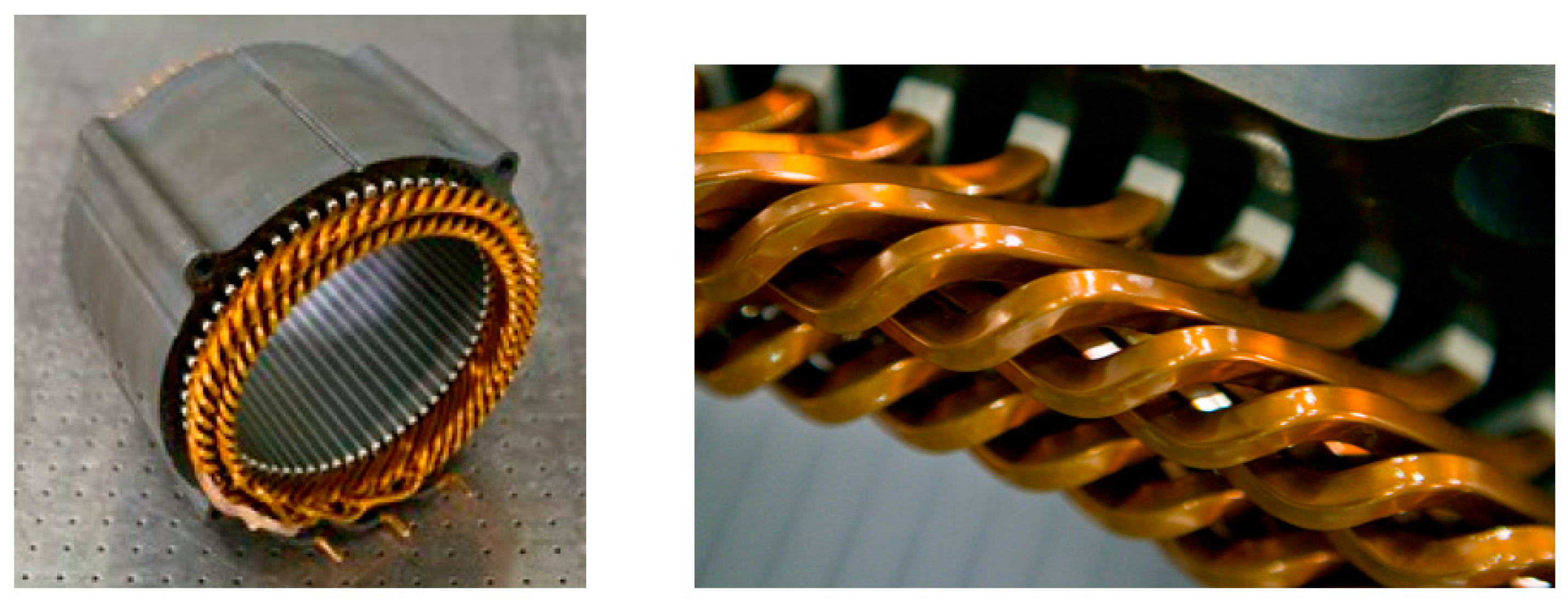
2. Bar Winding
2.1. Slot and Bar Winding
- -
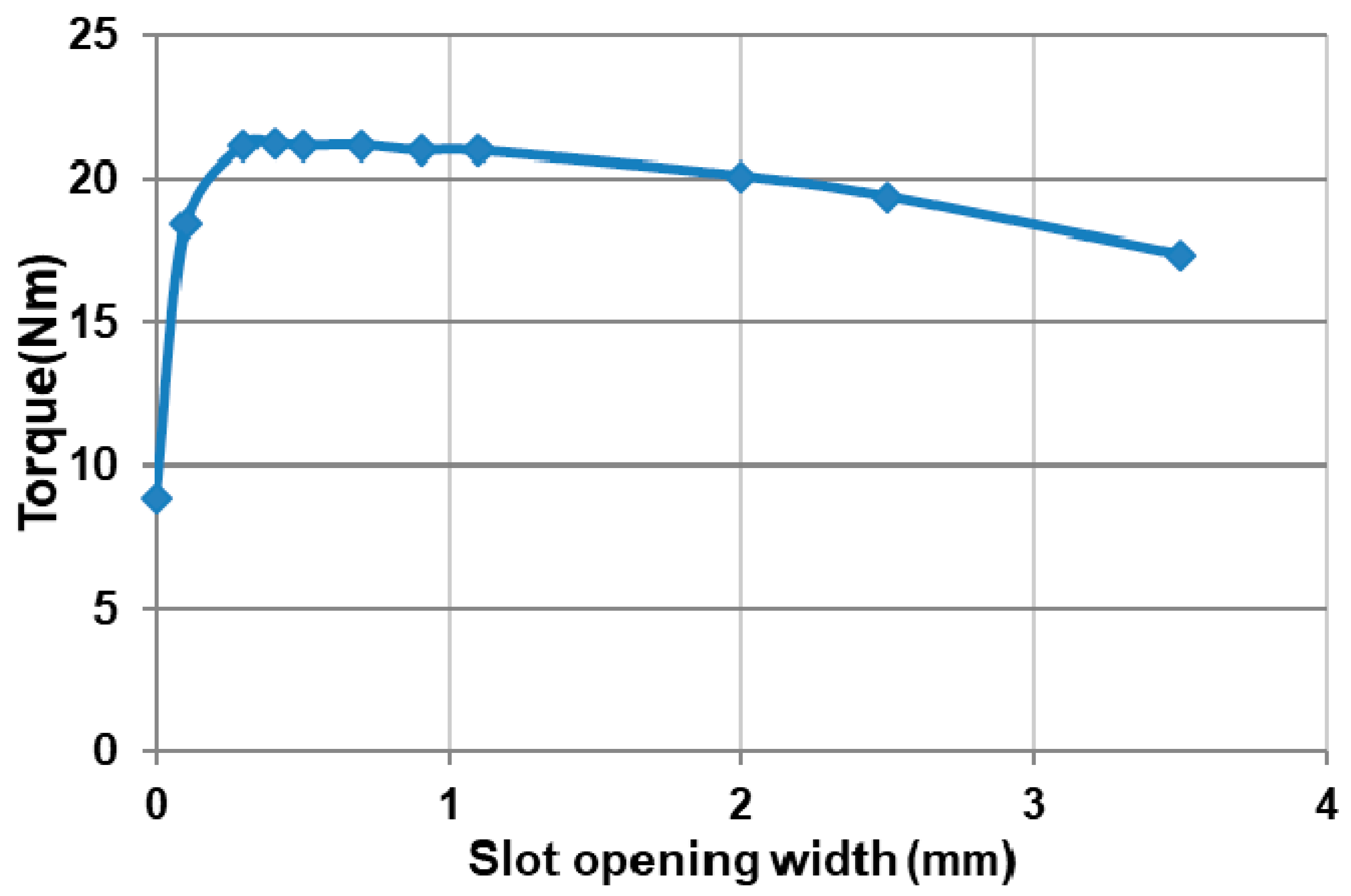
- The output torque, because the field modulations produced due to the stator slots, impacts the fundamental of the magnetic induction;
- -
- The cogging torque, due to the interaction between the magnet and the tooth, creates a smoother stator (closed slot) although that of the cogging torque is low. This can also lead to improvements in the vibratory and acoustic behavior of the motor;
- -
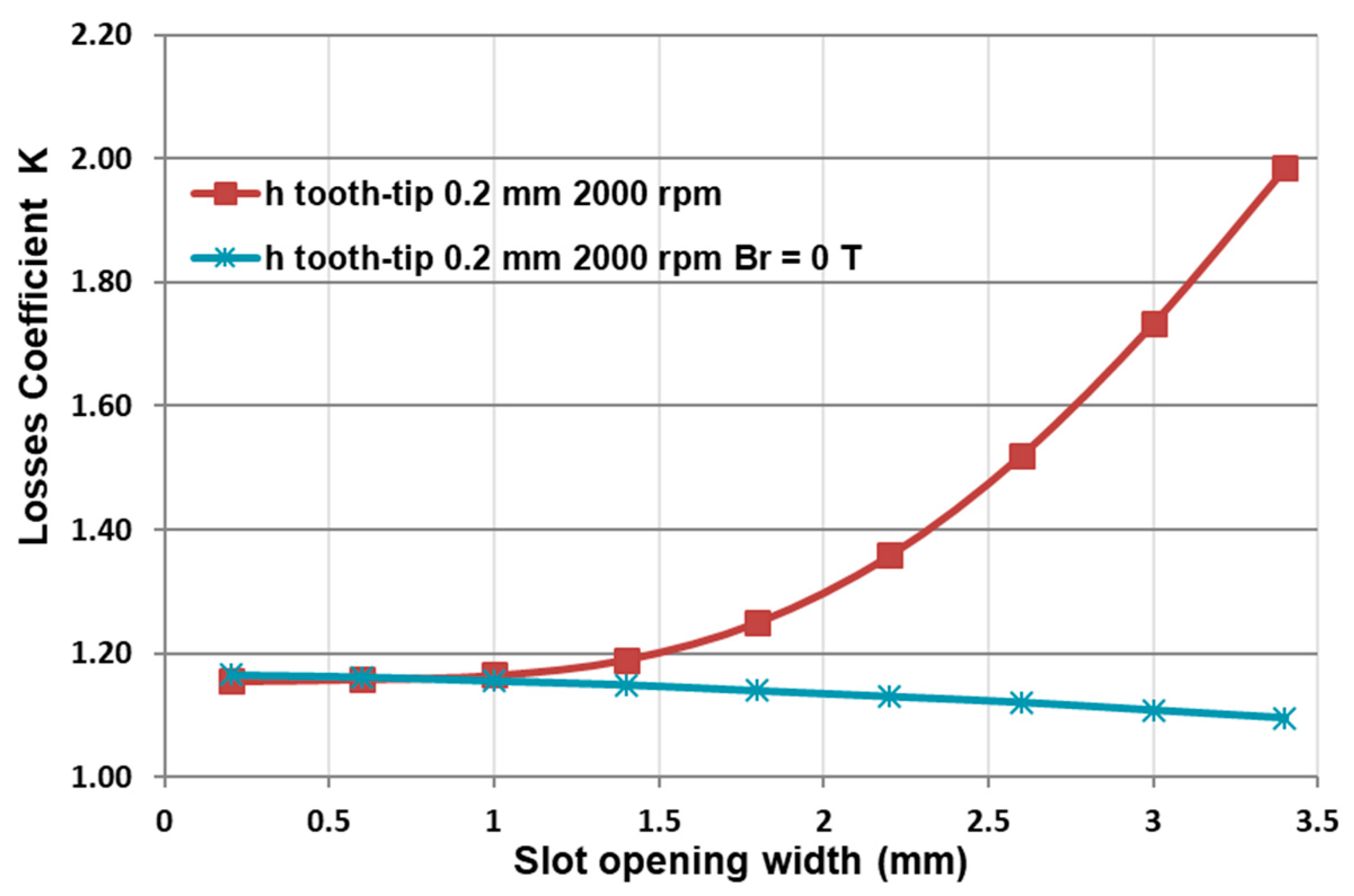
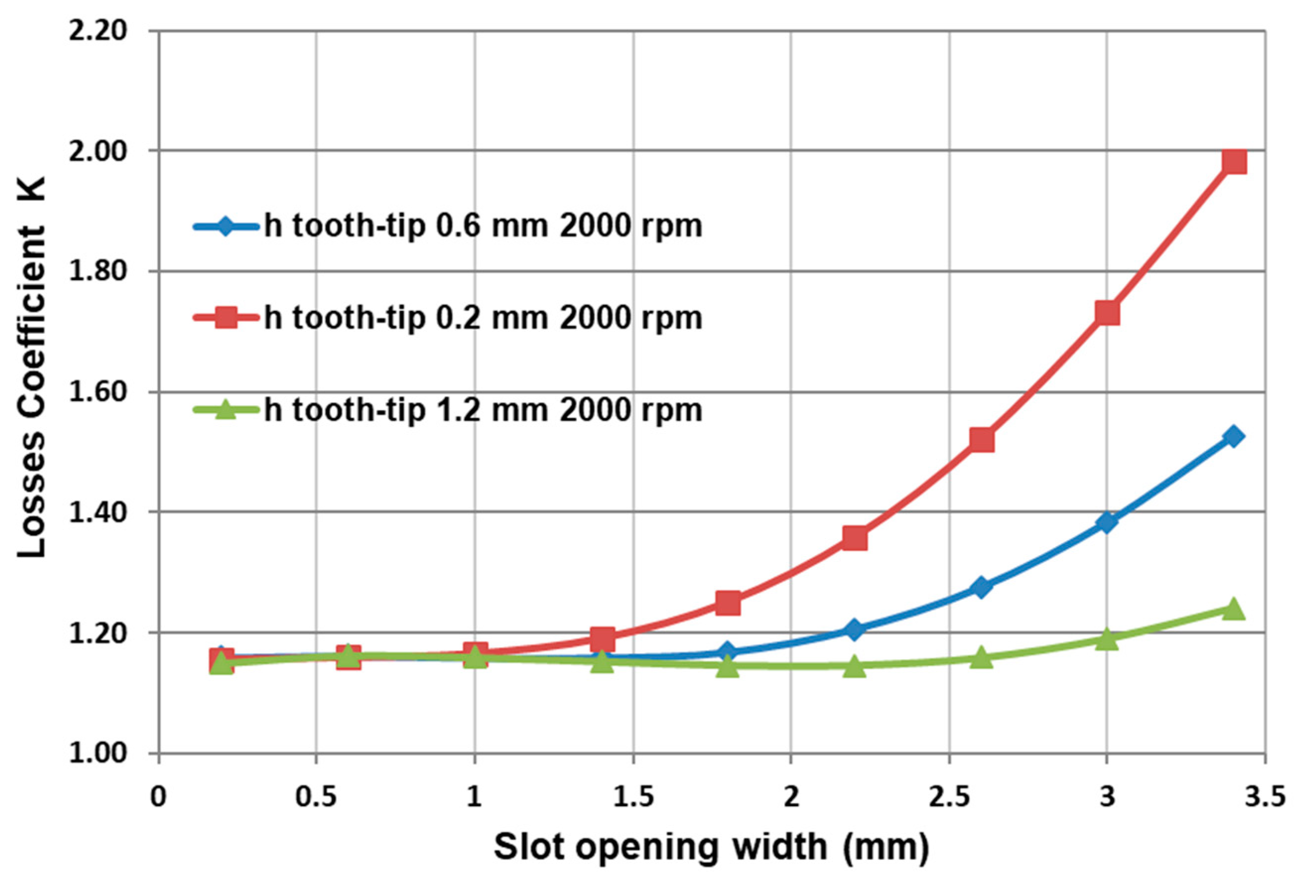
- Losses by induced currents in the magnets or a small slot opening significantly attenuates the variation of the permeance seen by the rotor and consequently less losses by induced currents, less heating and better motor efficiency. We have the same problem when the motor has a conductive metal sleeve (e.g., Inconel which has a high resistivity).
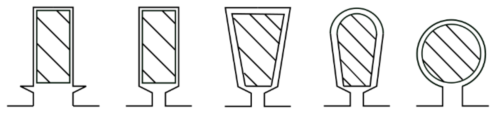
2.2. Additional Losses in the Bar
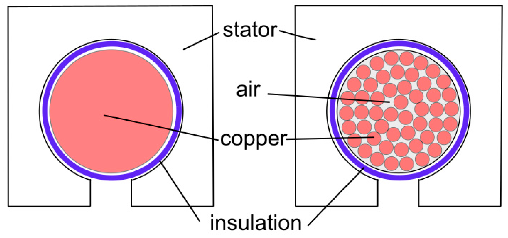
- High filling rate (80% filling instead of 30%);
- Reduced iron-copper thermal resistance;
- The slot can be very closed;
- Very compact coil heads;
- Simplified winding design, robustness and reliability.
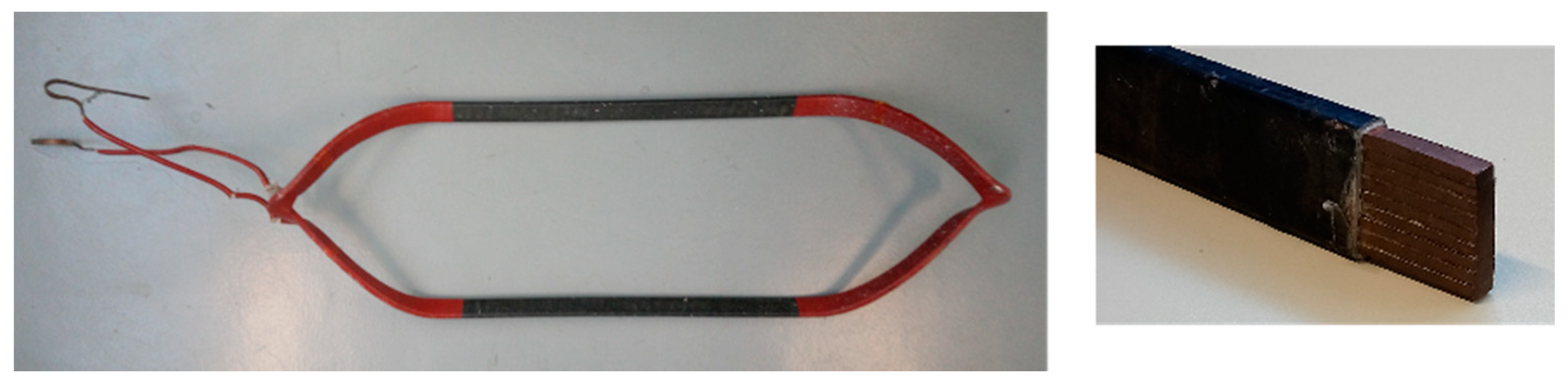
2.3. Winding Overhang for the Bar Winding
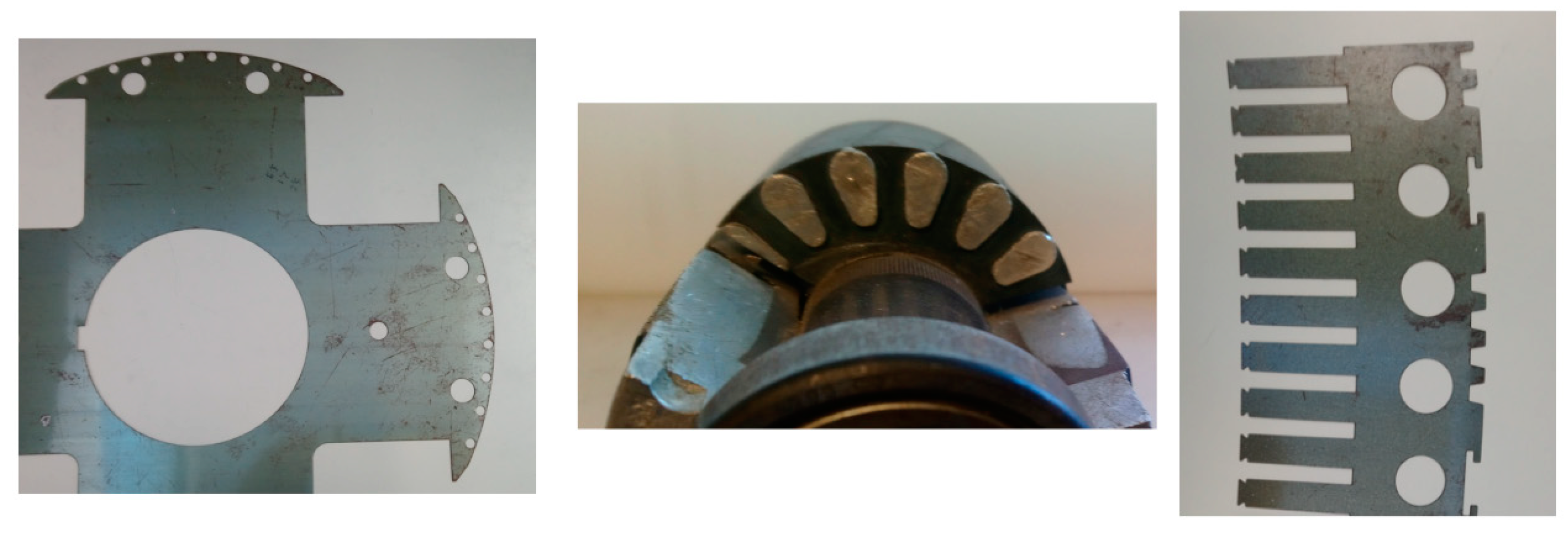
3. Application-Prototype
3.1. Motor Characteristics
- Improved energy efficiency;
- Flexible design capability;
- Reduced internal volume;
- Excellent maneuverability;
- Significant reduction in the size and weight of the machinery on board the boat;
- Use of the thruster as a rudder;
- Simplification of the propeller machine linkage.
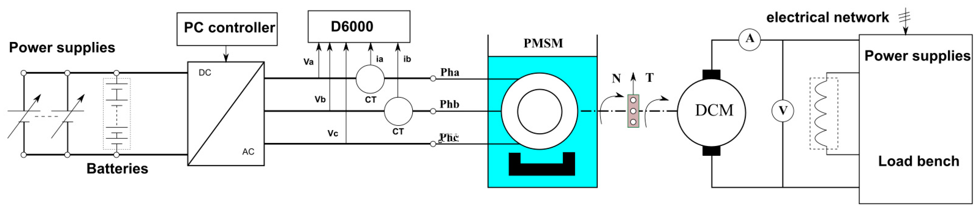
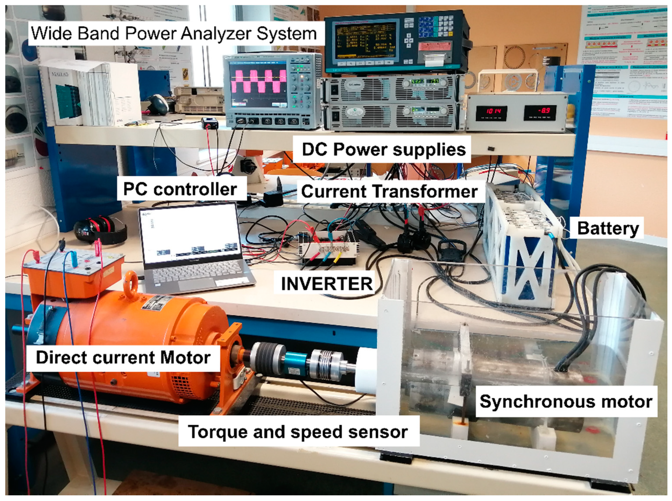
3.2. Measurement Bench
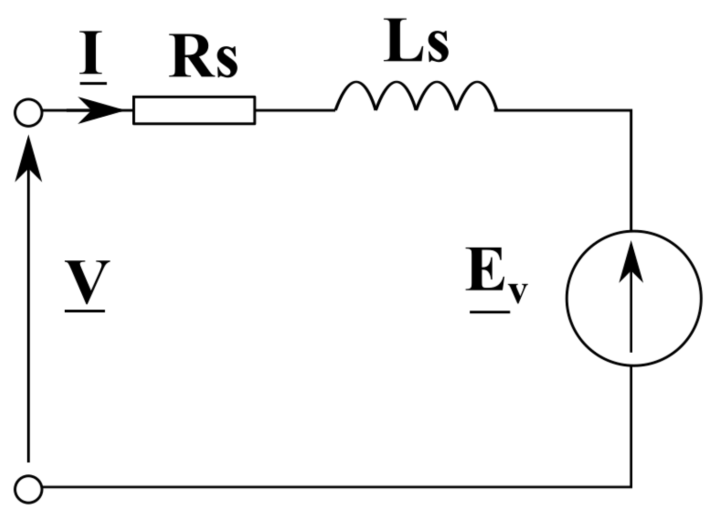
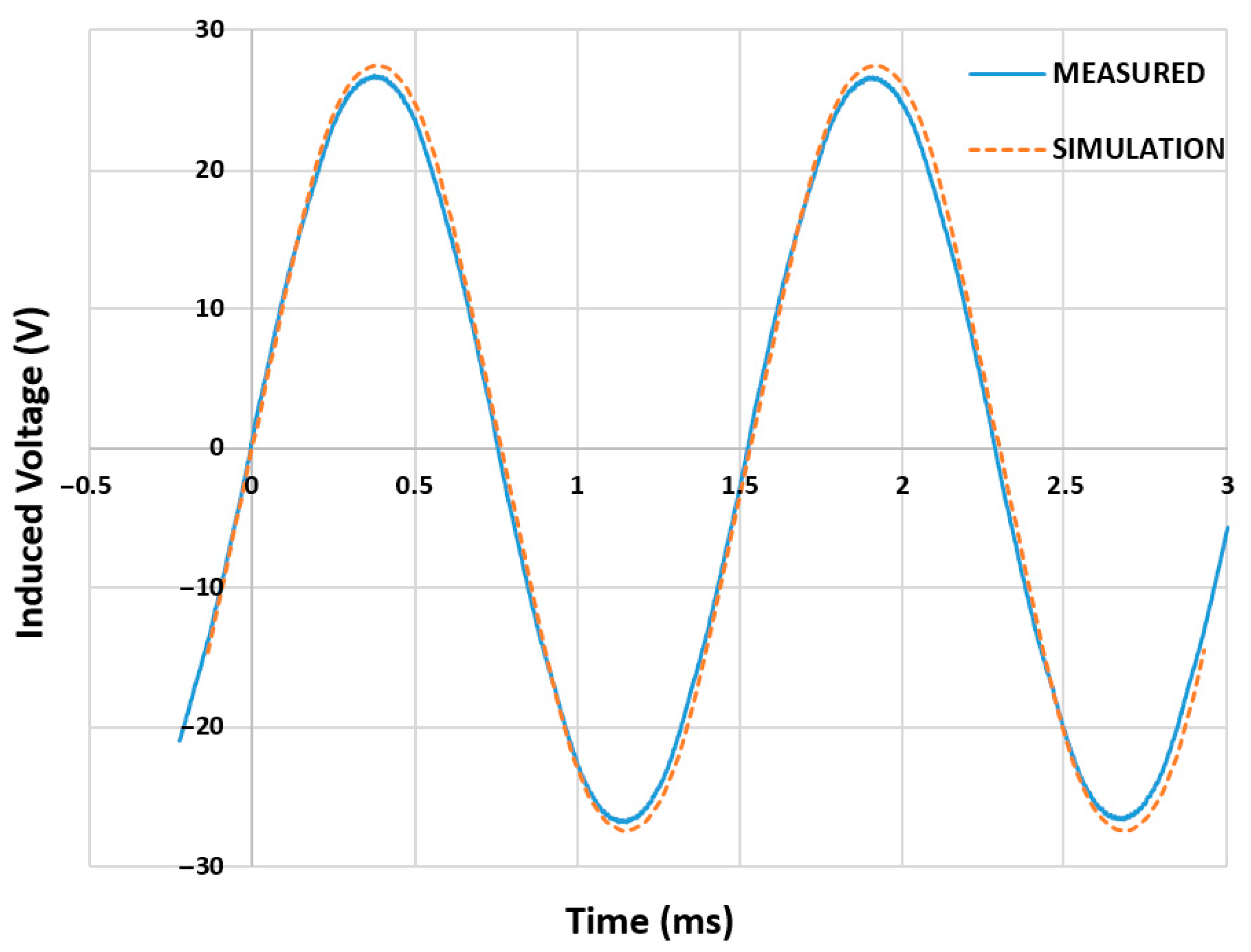
3.3. Electrical and FEA Characterizations
3.4. Load Test
4. Parametric Influences
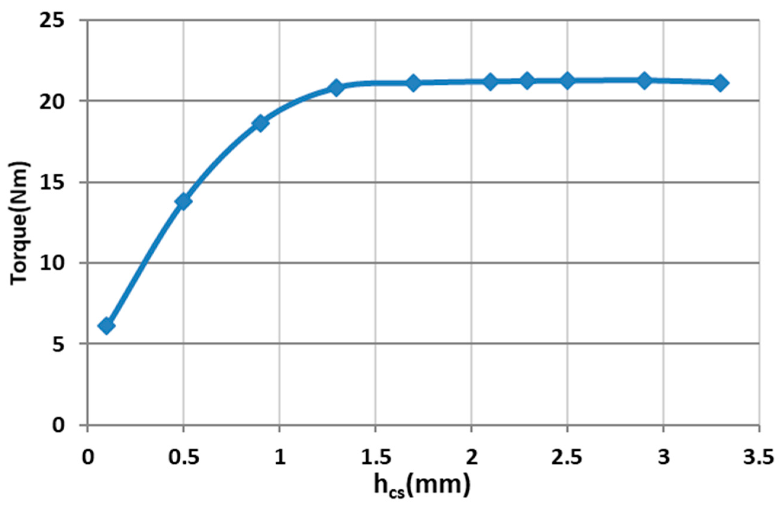
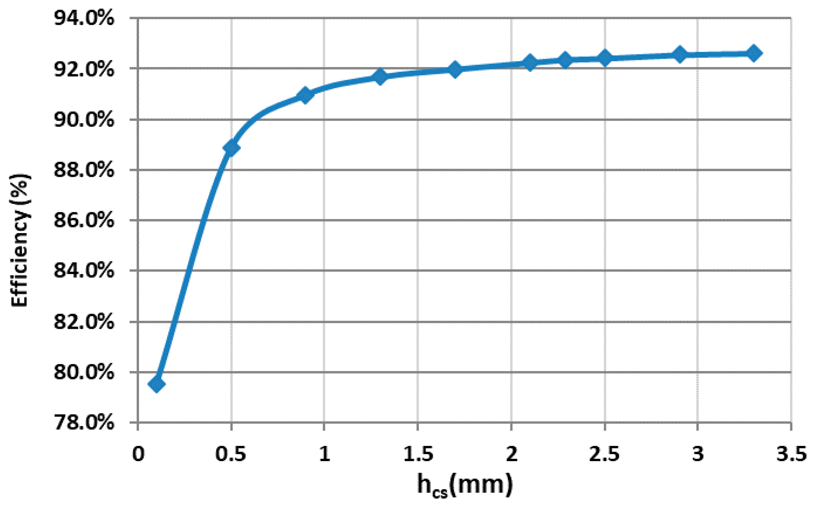
4.1. Study of Stator Yoke
4.2. Influence of Number of Slot/Numer of Pole
5. Conclusions
Author Contributions
Funding
Data Availability Statement
Acknowledgments
Conflicts of Interest
References
- ICAO Environmental Report 2016; The Environment Branch of the International Civil Aviation Organization (ICAO): Montréal, QC, Canada, 2016; Available online: https://www.icao.int/environmental-protection/pages/env2016.aspx (accessed on 2 September 2019).
- Troncon, D.; Alberti, L.; Bolognani, S.; Bettella, F.; Gatto, A.; Agritalia, C.; Spa, C. Electrification of agricultural machinery: A feasibility evaluation. In Proceedings of the Fourteenth International Conference on Ecological Vehicles and Renewable Energies (EVER), Monte-Carlo, Monaco, 8–10 May 2019. [Google Scholar] [CrossRef]
- Postiglione, C.; Collier, D.; Dupczak, B.; Heldwein, M.; Perin, A. Propulsion system for an all electric passenger boat employing permanent magnet synchronous motors and modern power electronics. In Proceedings of the Electrical Systems for Aircraft, Railway and Ship Propulsion, Bologna, Italy, 16–18 October 2012. [Google Scholar] [CrossRef]
- 2006/95/EC. The European Parliament’s Low Voltage Directive, Official Journal of the European Union. 2016. Available online: https://www.legifrance.gouv.fr/jorf/id/JORFTEXT000000696472 (accessed on 14 February 2020).
- Matt, D.; Boubaker, N.; Aitakkache, M.; Enrici, P.; Huselstein, J.J.; Martire, M. High power very low voltage motor for electric vehicle. In New Perspectives on Electric Vehicles; IntechOpen: London, UK, 2020. [Google Scholar] [CrossRef]
- Enrici, P.; Jac, J.; Ziegler, N.; Dumas, F.; Matt, D. Actuators with Toothed Coupling for the Electrification of a landing gear. IET Electr. Power Appl. 2018, 12, 739–746. [Google Scholar] [CrossRef]
- Rezzoug, A.; El-Hadi Zaim, M. Non-Conventional Electrical Machines, 1st ed.; Wiley-ISTE: London, UK, 2013; ISBN 978-1-118-60410-6. [Google Scholar]
- Bianchi, N.; Berardi, G. Analytical Approach to Design Hairpin Windings in High Performance Electric Vehicle Motors. In Proceedings of the Energy Conversion Congress and Exposition (ECCE), Portland, OR, USA, 23–27 September 2018. [Google Scholar] [CrossRef]
- Cai, W.; Fultton, D.; Congdon, C.L. Multi-Set Rectangular Copper Hairpin Windings for Electric Machines. U.S. Patent Application US7034428 B2, 25 April 2006. [Google Scholar]
- Cci, W. Terminals and Connections between multi-Set Segmented Hairpin Windings. U.S. Patent Application US20080042508 A1, 21 February 2008. [Google Scholar]
- Enrici, P.; Boubaker, N.; Matt, D. Bar Winding for the Low-Voltage Motorization of an Electric Tractor. In Proceedings of the International Conference on Electrical Machines (ICEM), Gothenburg, Sweden, 23–26 August 2020. [Google Scholar] [CrossRef]
- Matt, D.; Boubaker, N. Very Low Voltage and High Efficiency Motorisation for Electric Vehicles. In Emerging Electric Machines—Advances, Perspectives and Applications; IntechOpen: London, UK, 2021. [Google Scholar] [CrossRef]
- Enrici, P.; Meny, I.; Matt, D. Conceptual Study of Vernier Generator and Rectifier Association for Low Power Wind Energy System. Special Issue Power Converter of Electric Machines, Renewable Energy Systems, and Transportation. Energies 2021, 14, 666. [Google Scholar] [CrossRef]
- Field, A. Eddy currents in large slot-wond conductors. Trans. AIEE 1905, XXIV, 761–788. [Google Scholar] [CrossRef]
- Belot, A. Course of the Ecole supérieure d’Electricité. In Calcul des Machines Electriques Tournantes; ESE: Gif-sur-Yvette, France, 1976. [Google Scholar]
- Ondel, O. Diagnostic par Reconnaissance Des Formes: Application à un Ensemble Convertisseur—Machine Asynchrone. Ph.D. Thesis, Ecole centrale de Lyon, Écully, France, 2006. [Google Scholar]
- Boubaker, N. Study of Atypical Losses in High Performance Permanent-Magnet Synchronous Machines for Aircraft Applications. Ph.D. Thesis, University of Montpellier, Montpellier, France, 2016. [Google Scholar]
- Piscini, L. Study of a High Frequency and High Performance Machine for an Aeronautical Application. Ph.D. Thesis, University of Montpellier, Montpellier, France, 2020. [Google Scholar]
- Piscini, L.; Matt, D.; Gimeno, A.; Boubaker, N. Contribution on AC bar windings losses reduction for a high frequency and high performance machine for aeronautical application. In Proceedings of the 19th International Symposium on Electromagnetic Fields in mechatronics, Electrical and Electronic Engineering (ISEF), Nancy, France, 29–30 August 2019. [Google Scholar] [CrossRef]
- Gillon, E. Electrotechnique—Machines Electriques, Volume II. In Notions Complémentaires, 3rd ed.; Dunod Éditeur: Paris, France, 1964. [Google Scholar]
- Liwschitz, M. Calcul des Machines Électriques; Tome, I., Ed.; Editions SPES: Lausanne, Switzerland, 1967. [Google Scholar]
- Kostenko, M.; Piotrovski, L. Machines à Courant Alternatif. Machines Électriques, 3rd ed.; Tome II, Edition de Moscou; Technique soviétique: Moscou, Russia, 1969. [Google Scholar]
- Alger, P.L. Induction Machines; Gordon and Breach: Montreux, Switzerland, 1970. [Google Scholar]
- Jufer, M. Electromécanique; Éditions Dunod: Paris, France, 1986. [Google Scholar]
- Khaorapapong, T. Modélisation D’ordre Non Entier Des Effets de Fréquence Dans Les Barres Rotoriques D’une Machine Asynchrone. Ph.D. Thesis, Institut National Polytechnique de Toulouse, Toulouse, France, 2001. [Google Scholar]
- Dowell, P.L. Effects of eddy currents in transformer windings. Proc. IEE 1966, 113, 1387–1394. [Google Scholar] [CrossRef]
- Ferreira, A. Improved analytical modeling of conductive losses in magnetic components. IEEE Trans. Power Electron. 1994, 9, 127–131. [Google Scholar] [CrossRef]
- Emde, F. Einseitige Stromverdrängung in Ankernuten. Elektrotechnik Masch. 1908, 26, 703–707, 726–731. [Google Scholar]
- Dreyfus, L. Wirbelstromverluste in massiven Ankerleitern bei Leerlauf. Arch. Elecktrotechnik 1917, 6, 327–358. [Google Scholar] [CrossRef][Green Version]
- Roth, E. Etudes des pertes supplémentaires dans les barres câblées. Rev. Générale L’electricite 1917, 2, 323–336. [Google Scholar]
- Roth, E. Barre câblées et barres subdivisées dans les machines à courant alternative. Rev. Générale L’electricite 1918, 4, 192–198. [Google Scholar]
- Butterworth, S. Eddy-Current Losses in Cylindrical Conductors, with Special Applications to the Alternating Current Resistances of Short Coils. Philos. Trans. R. Soc. Lond. Ser. A Contain. Pap. A Math. Phys. Character 1922, 222, 57–100. [Google Scholar] [CrossRef]
- Lyon, W.V. Heat losses in the conductors of alternating current machines. Trans. Am. Inst. Electr. Eng. 1921, XL, 1361–1409. [Google Scholar] [CrossRef]
- Lyon, W.V. Heat losses in stranded armature conductors. J. AIEE 1922, 41, 37–49. [Google Scholar] [CrossRef]
- Oberrelt, K. Zusätzliche Wirbelstromverluste in Nutenleitern infolge eindringenden Luftspaltfeld (Additional eddy current losses in slot conductors due to air gap field). Arch. Elektrotechnik 1978, 60, 121–127. [Google Scholar]
- Reatti, A.; Kazimierczuk, M. Comparison of various methods for calculating the ac resistance of inductors. IEEE Trans. Magn. 2002, 38, 1512–1518. [Google Scholar] [CrossRef]
- Wrobel, R.; Mlot, A.; Mellor, P.H. Investigation of end-winding proximity losses in electromagnetic devices. In Proceedings of the XIX International Conference on Electrical Machines (ICEM), Rome, Italia, 6–8 September 2010. [Google Scholar] [CrossRef]
- Paradkar, M.; Böcker, J. Analysis of eddy current losses in the stator windings of IPM machines in electric and hybrid electric vehicle applications. In Proceedings of the 8th IET International Conference on Power Electronics, Machines and Drives (PEMD), Glasgow, UK, 19–21 April 2016. [Google Scholar] [CrossRef]
- Stoll, R.L. The Analysis of Eddy Current; Clarendon Press: Oxford, UK, 1974. [Google Scholar]
- Belkaid, Z. Models and Tools for the Design of HF Magnetic Components Dedicated to Power Electronics. Ph.D. Thesis, University of Montpellier, Montpellier, France, 2016. [Google Scholar]
- Wikipedia. Available online: https://fr.wikipedia.org/wiki/Fonction_de_Kelvin-Bessel (accessed on 22 October 2021).
- Swann, S.A. Effective resistance and reactance of a solid cylindrical conductor placed in a semi-closed slot. Proc. IEE Monogr. 1962, 527, 611–615. [Google Scholar] [CrossRef]
- Levasseur, A. Nouvelles formules, valables à toutes les fréquences, pour le calcul rapide de l’effet Kelvin. J. Phys. Radium 1930, 1, 93–98. [Google Scholar] [CrossRef]
- Filliau, G.; Bondu, A.; Mazodier, L. Le Navire Tout Électrique—Propulsion et Production D’énergie. Technique de l’ingénieur, D5610v1. 2000. Available online: https://www.techniques-ingenieur.fr/base-documentaire/archives-th12/archives-reseaux-et-applications-tiadc/archive-1/le-navire-tout-electrique-d5615/ (accessed on 22 October 2021).


| Designation | Numerical Value | Units |
|---|---|---|
| Outer diameter De | 110 | mm |
| Length motor Lz | 150 | mm |
| Air gap e | 1 | mm |
| Air gap radius Re | 48 | mm |
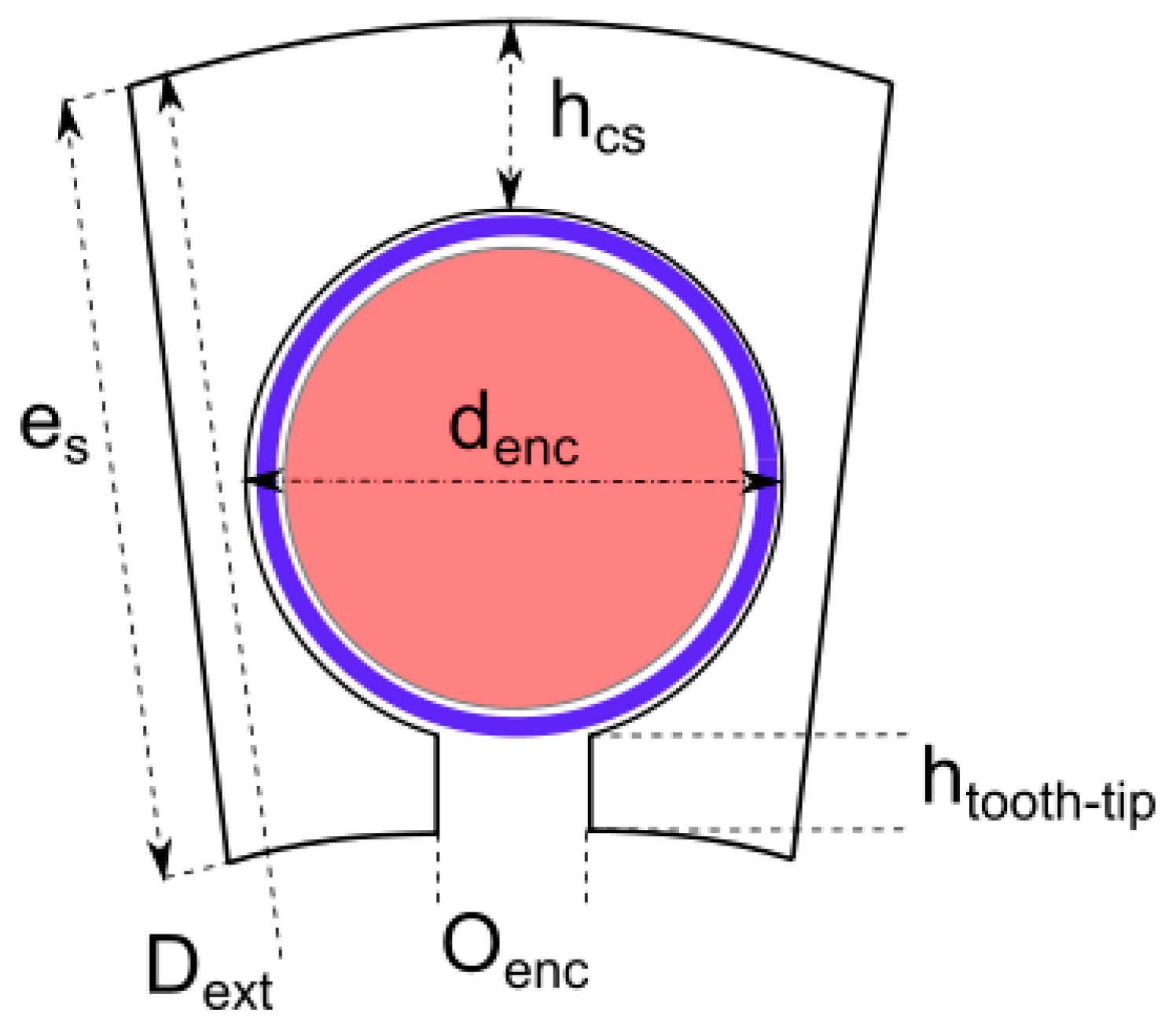
| Height of stator yoke hcs | 2.24 | mm |
| Bar diameter db | 3 | mm |
| Slot diameter denc | 3.6 | mm |
| Slot opening oenc | 0.4 | mm |
| Tooth-tip height | 1.16 | mm |
| Magnet height | 4.5 | mm |
| Magnet width | 4.84 | mm |
| Height of rotor yoke | 3 | mm |
| Designation | Measurement | Simulation | Units |
|---|---|---|---|
| Resistance of one phase and cable: Rs + Rcable | 10.8 | 10.9 | mΩ |
| Constant of e.m.f.: Ke | 0.067 | 0.072 | V.s.rad−1 |
| Torque coefficient: KT | 0.18 | 0.21 | Nm.A−1 |
| Synchronous Inductance: Ls | 16 | 16.4 | mH |
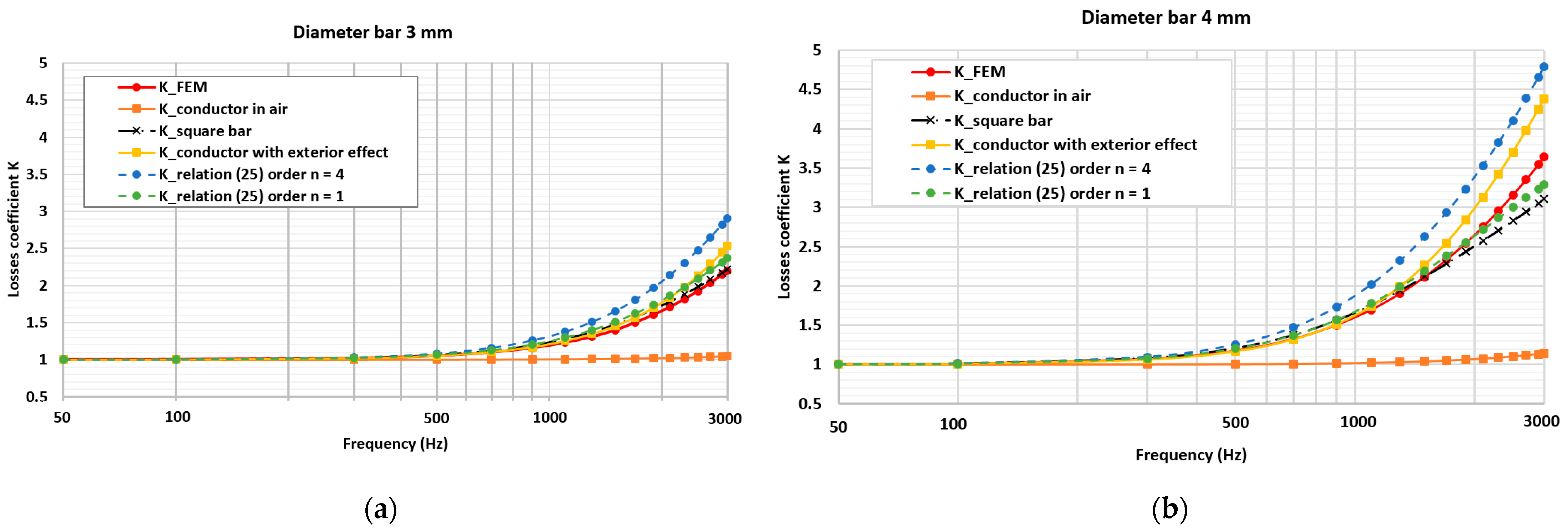
| Speed/Frequency | K Measured | K_Ext | K_Square | K_n = 1 | K FEM |
|---|---|---|---|---|---|
| 1000 rpm/433 Hz | 1.30 | 1.06 | 1.07 | 1.06 | 1.04 |
| 1250 rpm/542 Hz | 1.12 | 1.09 | 1.10 | 1.09 | 1.06 |
| 1500 rpm/650 Hz | 1.21 | 1.10 | 1.12 | 1.17 | 1.09 |
| Designation | Prototype | Optimized Motor |
|---|---|---|
| Stator thickness es [mm] | 7 | 5 |
| hcs [mm] | 2.24 | 1.3 |
| histhm [mm] | 1.16 | 0.2 |
| Oenc [mm] | 0.4 | 0.4 |
| Denc [mm] | 3.6 | 3.5 |
| Magnet height [mm] | 4.5 | 4.5 |
| Magnet width [mm] | 4.84 | 5 |
| Current [A] | 100 | 92 |
| Torque [N·m] | 21 | 21 |
| Winding Losses [W] | 203 | 178 |
| Stator core loss [W] | 63 | 70 |
| Rotor Core loss [W] | 0.74 | 0.61 |
| Losses due to induced currents in the Magnets [W] | 0.82 | 0.69 |
| Efficiency [%] | 92 | 93 |
| Number of Slots/Number of Poles | 51/52 | 45/46 | 39/40 | 33/34 |
|---|---|---|---|---|
| Dia bar [mm] | 3 | 4 | 4 | 4 |
| Stator thickness es [mm] | 5 | 6 | 6.5 | 7.1 |
| Air gap radius [mm] | 50 | 49 | 48.5 | 47.9 |
| hcs [mm] | 1.3 | 1.2 | 1.7 | 2.3 |
| histhm [mm] | 0.2 | 0.2 | 0.2 | 0.2 |
| Oenc [mm] | 0.4 | 0.4 | 0.4 | 0.4 |
| Denc [mm] | 3.5 | 4.6 | 4.6 | 4.6 |
| Magnet height [mm] | 4.5 | 4.5 | 4.5 | 4.5 |
| Magnet width [mm] | 5 | 5.6 | 6.4 | 7.5 |
| Current [A] | 92 | 105 | 112 | 127 |
| Torque [N·m] | 21 | 21 | 21 | 21 |
| Winding Losses [W] | 178 | 126 | 118 | 124 |
| Core loss [W] | 71 | 76 | 69 | 58 |
| Efficiency [%] | 93 | 94.1 | 94.4 | 94.5 |
Publisher’s Note: MDPI stays neutral with regard to jurisdictional claims in published maps and institutional affiliations. |
© 2022 by the authors. Licensee MDPI, Basel, Switzerland. This article is an open access article distributed under the terms and conditions of the Creative Commons Attribution (CC BY) license (https://creativecommons.org/licenses/by/4.0/).
Share and Cite
Aitakkache, M.; Enrici, P.; Matt, D.; Boubaker, N.; Piscini, L. Concept, Feasibility of Cylindrical Bar Winding for Low Voltage Permanent Magnet Synchronous Motor. Energies 2022, 15, 1507. https://doi.org/10.3390/en15041507
Aitakkache M, Enrici P, Matt D, Boubaker N, Piscini L. Concept, Feasibility of Cylindrical Bar Winding for Low Voltage Permanent Magnet Synchronous Motor. Energies. 2022; 15(4):1507. https://doi.org/10.3390/en15041507
Chicago/Turabian StyleAitakkache, Mourad, Philippe Enrici, Daniel Matt, Nadhem Boubaker, and Lorenzo Piscini. 2022. "Concept, Feasibility of Cylindrical Bar Winding for Low Voltage Permanent Magnet Synchronous Motor" Energies 15, no. 4: 1507. https://doi.org/10.3390/en15041507
APA StyleAitakkache, M., Enrici, P., Matt, D., Boubaker, N., & Piscini, L. (2022). Concept, Feasibility of Cylindrical Bar Winding for Low Voltage Permanent Magnet Synchronous Motor. Energies, 15(4), 1507. https://doi.org/10.3390/en15041507