Abstract
This paper reports the design of a magnetic-geared permanent magnet synchronous motor (MG-PMSM) for a 45 kW tram traction system based on high torque density. In the case of the existing tram driving system, due to mechanical reduction gear and induction motor, it causes power transmission loss, low efficiency, and difficulty in lightweight. To solve this problem, research on the MG-PMSM, which combines a contactless magnetic gear with a high-power-density PMSM, is being actively conducted. This motor has a double rotor structure, and the inner rotor, including permanent magnet, and the outer rotor composed of pole-pieces rotate at different mechanical speeds. However, it is hard to design a tram driving system with a high torque density within limited conditions, because only one rotor in MG-PMSM is used as an output. In addition, there is no study conducted from basic design to final design, including gear ratio and topology selection in MG-PMSM for tram. Therefore, this paper presents the design process of MG-PMSM with high torque density to be applied to the 45 kW–class tram driving system. After designing the magnetic gear part that increases torque and efficiency by selecting an appropriate topologies-and-gear ratio that meets the constraints, the final finite elements method (FEM) model and electromagnetic field analysis results were derived by considering the number of poles and the number of slots. Through this, we confirmed that it is superior in output characteristics compared to the existing induction motor + mechanical gear.
1. Introduction
Recently, as energy cost-saving and efficiency become important in the traction-motor industry, including railway vehicles, various studies are being conducted to improve the power density. With this paradigm, the traction motor is changing from the existing induction motor to the high-output PMSM, but there are still limitations in tram. Figure 1 shows the structure of a low-floor bogie for tram. As shown in Figure 1, in the existing driving system for trams, the equipment is installed outside the wheel instead of inside, because there is not enough space under the vehicle. For this reason, the mechanical reduction gear has a structure that is vertically connected to the axle, which makes the system complex and hinders weight reduction and minimization. In addition, the mechanical reduction gear causes a continuous maintenance problem, noise, vibration, power loss, etc. According to the South Korean high-speed railway KTX, there were 126 cases of failure due to maintenance problems of mechanical gear from 2004 to 2020, resulting in an annual economic loss of $55 M. Thus, it is difficult to secure torque density, although trams require low-speed and high-torque output compared to other applications. Accordingly, research on MG-PMSM in which a non-contact magnetic gear and a high-torque PMSM are integrally combined has been actively conducted. Figure 2 shows a cross-sectional and a developed view of MG-PMSM. The MG-PMSM is a system in which an inner rotor, including a permanent magnet, and an outer rotor composed of a ferromagnetic material called a pole-piece rotate at different speeds. MG-PMSM is the same as the operation principle of magnetic gear. In the case of a magnetic gear, ferromagnetic material called pole-pieces exists between two permanent magnets and modulates the magnetic flux generated from the permanent magnets in the air-gap. This modulated magnetic flux causes the permanent magnet rotor and the pole-pieces to rotate at different speeds, which means the gear ratio. Accordingly, the continuous variable transmission (CVT) type, which is the basic form of MG-PMSM, replaces the outer permanent magnet with the stator in the magnetic gear. In contrast to mechanical gears in which gears are intermeshed directly to transmit power, this has a non-contact transmission method through attraction and repulsion, and there is little transmission loss compared to the mechanical gear [1,2,3,4,5]. In this regard, K. Atallah, C.G.C. Neves, and N. Misron presented the principle of modulated air-gap flux through magnetic gear, and H. Zhao and M. Cheng studied MG-PMSM for traction of electric vehicles [6,7,8,9,10]. Figure 3 shows the change from the conventional driving system to MG-PMSM. It can be advantageous in terms of sizing and torque density compared to the existing mechanical gear + electric motor. However, it is difficult to maximize the torque density, because only one output of double rotor should be used, and the specification is limited in the tram driving system. Moreover, the characteristics of the motor are very different for each type, topology, and gear ratio, and previous studies, such as those by Y.Wang, Le Sun, K. Shin, and H. Shin [11,12,13,14], have focused only on the CVT type. Therefore, this paper introduces the MG-PMSM to generate a high torque density for 45 kW tram and presents the design process that can derive a suitable FEM model considering various variables.
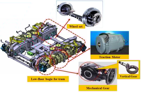
Figure 1.
Structure of low-floor bogie and components for tram.
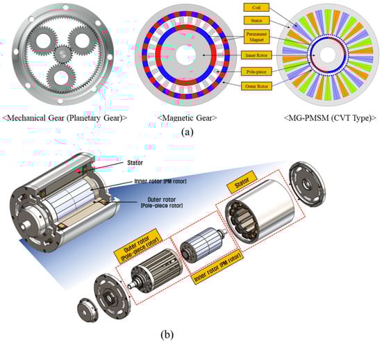
Figure 2.
Structural diagram of MG-PMSM: (a) Cross-sectional view (b) Development view.
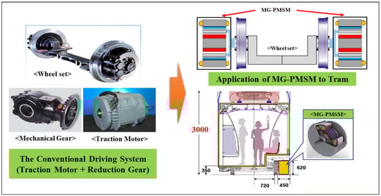
Figure 3.
Change from conventional driving system to MG-PMSM for tram.
2. The Operation Principle of MG-PMSMs
Although the output characteristics of MG-PMSM may vary by type, it basically follows the principle of magnetic gear. Figure 4 shows a cross-sectional view of a magnetic gear and a linear model of it. The magnetic gear has permanent magnets on the inside and outside, and a pole-piece made of a ferromagnetic material between them. Depending on which of these three parts is fixed and rotated, the rotation direction and output will differ. In this paper, it is assumed that the inner rotor and pole-piece rotate, while the outer permanent magnet is fixed.
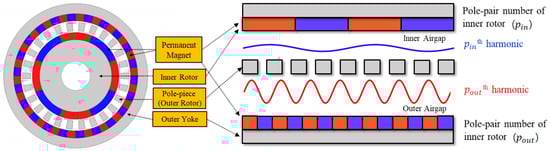
Figure 4.
Cross-sectional and linear models of MG-PMSM to explain the flux modulation effect.
Figure 5 shows the magnetomotive force (MMF), , generated by the inner or outer permanent magnets, and relative permeance of pole-piece, , in magnetic gear, respectively. The equation for these can be expressed as follows, using the Fourier series:
where is the MMF amplitude of the m- and n-th order harmonic, is the permeance amplitude of the k-th order harmonic, is the number of pole-pieces, is the number of the inner or outer PM pole pairs, is the mechanical speeds of inner rotor and pole-piece rotor, and is the air-gap circumferential position. Just as the MMF of PM or armature in the PMSM is modulated by the slotting effect, the air-gap flux density of the magnetic gear is also expressed as the product of the MMF of PMs and relative permeance of pole-piece. Thus, the modulated air-gap flux density can be expressed as follows:
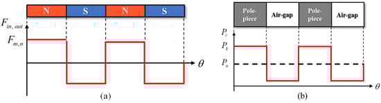
Figure 5.
MMF distribution generated by the PMs and pole-piece relative permeance function: (a) MMF (b) permeance.
In this paper, only the air-gap flux density in the radial direction is used to simplify the equation. In order to generate a steady torque, the number of pole pairs and the speeds of the two air-gap flux densities should be the same. Therefore, the fundamental order of the inner air-gap flux density dc component should be the same as the harmonic order of the modulation component of the outer air-gap flux density , and its velocity term should also be the same. The equation for the above is as follows, and the magnetic gear is synchronized when Equations (6) and (7) are satisfied [6].
For this reason, since the electrical frequencies of the air-gap flux density of inner rotor and outer air-gap flux density modulated by the pole-piece are the same, when , the reciprocal on the ratio of the number of inner rotor pole pairs to the number of pole-pieces is the gear ratio (speed ratio), as follows.
3. Design Process of MG-PMSM
3.1. Design Specification
In the case of the induction motor applied to the existing tram, a vertical gear was used, and the system is complicated. Taking this into consideration, it is necessary to have a smaller size MG-PMSM than the existing motor + gear. Figure 6 shows the torque-speed curve of the high-torque/low-speed part (wheel side) on MG-PMSM for 45 kW–class trams, and Table 1 shows the specification. The torque at the rated speed (214 RPM) is 2004 Nm, and the torque at the maximum speed (599 RPM) is 716 Nm. The DC-Link terminal voltage is limited to 750 Vdc for the space vector pulse width modulation (SVPWM), and the back electromotive force is limited to 433 V. Also, the stator outer diameter is 520 mm and the axial length, including end-turn of winding, is 400 mm.
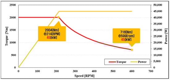
Figure 6.
Torque speed curve of 45 kW–class MG-PMSM for tram.

Table 1.
Design Specification of 45 kW–class MG-PMSM for tram.
3.2. Design Process
Figure 7 shows the MG-PMSM design process for a high torque density for a 45 kW tram driving system. First, the output characteristics of MG-PMSM vary depending on the topology, and it is important which application is used. Second, the optimal gear ratio combination is selected in consideration of the torque-ripple coefficient, unbalanced magnetic force (UMF). Compared to conventional motors, the MG-PMSM has a large performance difference depending on the number of pole pairs and the number of pole-pieces. Third, the magnetic gear is designed based on the optimal gear ratio. As is described later, in the topology of MG-PMSM that was selected in this research, it is important to design the gear part within a limited size, because the output is determined by this part. Finally, a stator suitable for the magnetic gear is designed while considering the magnetic and electric loading [15,16,17]. After going through the above process, the result using the FEM electromagnetic field analysis is obtained and it is checked whether the required output, as shown in Table 1, is satisfied.
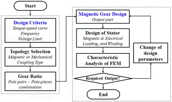
Figure 7.
MG-PMSM design process for high torque density of 45 kW–class tram driving system.
4. Derivation of MG-PMSM Model for 45 kW–Class Tram
4.1. Topology Selection
The output characteristics of the MG-PMSM vary greatly depending on the topology. Figure 8 shows two models according to the topology of the MG-PMSM. In the case of a magnetic coupling type, it is a model in which a magnetic gear and PMSM are magnetically coupled. This model is a system in which the number of stator and inner PM rotor poles does not match and the stator contributes to a magnetic gear. Therefore, when a load is applied, the output is distributed between the inner rotor and outer rotor (pole-pieces). In general, such a topology is called CVT type, and it is used when two outputs are used. On the other hand, a mechanical coupling type is a model in which a magnetic gear and PMSM are mechanically combined. It is a system in which the number of stator poles and the number of inner PM rotor poles coincide with each other, and the stator does not contribute to the magnetic gear. Therefore, the output generated from the inner rotor is transferred to the outer rotor (pole-pieces) as it is, and the final output is generated from the pole-piece part, such as the magnetic gear. In addition, since the stator operates in synchronization with the inner rotor, the control method is the same as that of the existing PMSM. Since there is no need to use two outputs in the tram, the mechanical-coupling type is more appropriate.
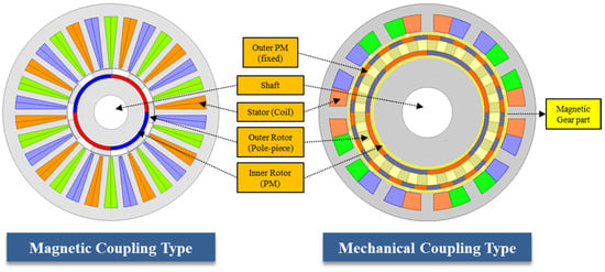
Figure 8.
Two models according to the topology of MG-PMSM.
4.2. Gear Ratio Selection
Since it is a motor with a double permanent magnet and pole-piece structure, the electromagnetic field varies greatly depending on combination of the number of pole-pairs and pole-pieces, as well as the topology. Therefore, it is important to find the optimal combination by considering the torque ripple coefficient () and UMF, using the following equation [18].
where is the least common multiple and is the greatest common multiple. In the case of the existing MG-PMSM, torque ripple occurs due to reluctance between the PM and the slot, and in the case of MG-PMSM, the magnetic equivalent air-gap between the rotor and the slot is very large, so the influence of torque ripple by the slot is small. Therefore, torque ripple by the PM rotor and pole-pieces is dominant, and, in general, the smaller this value (), the smaller the torque ripple. In addition, magnetic eccentricity due to the double air-gap structure may occur significantly in MG-PMSM. This can minimize UMF by designing to satisfy Equation (10), and it can work stably.
However, if the ripple coefficient is 1, then Equation (10) cannot be satisfied. For this reason, one of two equations should be weighted. Torque ripple can be reduced through optimization of design parameters, but UMF is relatively difficult, so the ripple coefficient is 2 and the combination was selected so that Equation (10) was satisfied. Table 2 shows the analysis result of the basic designed surface permanent magnet (SPM)-type magnetic gear part within the same criteria, while satisfying the above conditions. Four inner PM pole-pairs/22 pole-pieces/18 outer PM pole-pairs is the combination that satisfies the required rated torque and frequency, and has the smallest torque ripple; thus, it was selected as the optimal combination.
Table 2.
Analysis result of magnetic gear according to combination.
4.3. Design of Magnetic Gear Part
In MG-PMSM, the torque is determined by the magnetic gear part. Therefore, it is more advantageous to shorten the time to design a stator suitable for securing the required torque after the design of magnetic gear part. Table 3 shows the 2D FEM model of four inner pole-pairs/22 pole-pieces/18 outer pole-pairs interior permanent magnet (IPM) type of magnetic gear and specification of it. In fact, in terms of torque, it is advantageous to design the magnetic gear as an SPM type. This is because, in the case of the general IPM type, as shown in Figure 9, there is an additional piece on the inner rotor, which distorts the pole-piece permeance component. In addition, in contrast to PMSM, since it has a double-air-gap structure, the ratio of d-axis inductance to q-axis inductance is not large, so the reluctance torque is hardly generated. However, if the SPM type is applied as a driving system for the tram, there is a risk of permanent magnets scattering. Therefore, in this study, the q-axis barrier was connected to maintain the permeance of the inner rotor as a dc component, such as the SPM type, as much as possible, and bar-type PMs were embedded in order to secure mechanical rigidity.
Table 3.
Magnetic gear part for 45 kW–class MG-PMSM.
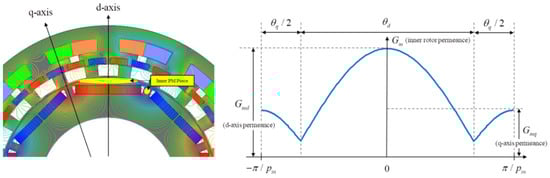
Figure 9.
Equivalent relative permeance for inner rotor of general IPM-type MG-PMSM.
For the outer permanent magnet, wedges were applied to the outer permanent magnet. The magnetic gear generates a lot of magnetic flux due to the use of a large number of PMs, and this additionally causes eddy current loss [19]. In particular, the loss occurs intensively in the part where the outer PMs meet, and wedges are added to solve this, as shown in Figure 10. When applying a wedge with a thickness of 1 mm, although torque is reduced from 3.05 to 2.56 kNm, the PM eddy current loss can be improved from 5.27 to 1.67 kW.
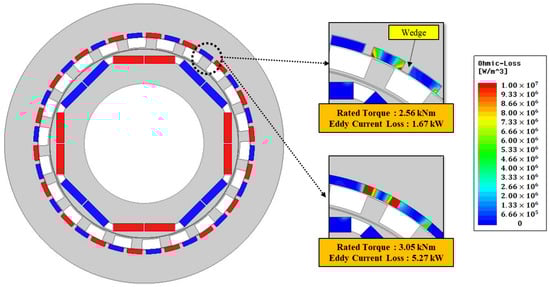
Figure 10.
Permanent magnet-loss distribution when wedges are applied.
In the case of pole-pieces, the angle is important factor in determining the waveform of relative permeance. Therefore, in order to maximize the torque by increasing the air-gap flux density, it is necessary to analyze the characteristics according to the angle of the pole-pieces. Figure 11 shows the pole-pieces (output) torque of magnetic gear at angle of 4 to 11 degrees, and it can be seen that it has the highest torque at 6 degrees.
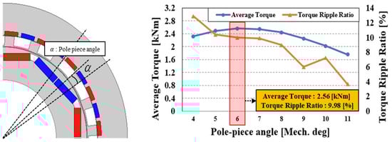
Figure 11.
Average torque and torque-ripple ratio according to pole-piece angle.
4.4. Design of MG-PMSM
In this session, a stator suitable for magnetic gear was designed to apply a load. In this study, an 8-inner pole 12-slot combination of fractional slot concentrated winding (FSCW) was selected. The first reason for this is that, when a concentrated winding method is used, the length of the end-turn winding can be minimized, so it can be more advantageous in size compared to the conventional electric motor for trams. Second, FSCW can generate additional torque via the magnetic gearing effect, as well as PMSM torque [20]. Reflecting this, Table 4 shows the specification of the 45 kW–class MG-PMSM final model, and Figure 12 shows the final model and electromagnetic-field-characteristics analysis’s results for 2D FEM MG-PMSM. Figure 12a shows the average torque and torque ripple ratio at rated speed on full-load, and it can be confirmed that the required torque 2004 Nm or more is satisfied. As shown in Figure 12c, it can be seen that the back-EMF below the voltage limit of 433 V is satisfied. MG-PMSM is a system that combines magnetic gear with PMSM, and the final model presented in this paper is about 94.0%, whereas the total efficiency of the existing driving system is about 89.2%, because the general induction motor for railway vehicles is about 92% and the mechanical gear is about 97%. In addition, considering that the weight of the driving system in the existing bimodal tram is 243 kg (motor [145 kg] + mechanical gear [98 kg]), as shown in Table 5, the power density for the total driving system is about 0.185 kW/kg. On the other hand, the power density of final model in this paper is 0.24 kW/kg, which is about 23% higher.
Table 4.
Design Specification of 45 kW–class MG-PMSM for tram.
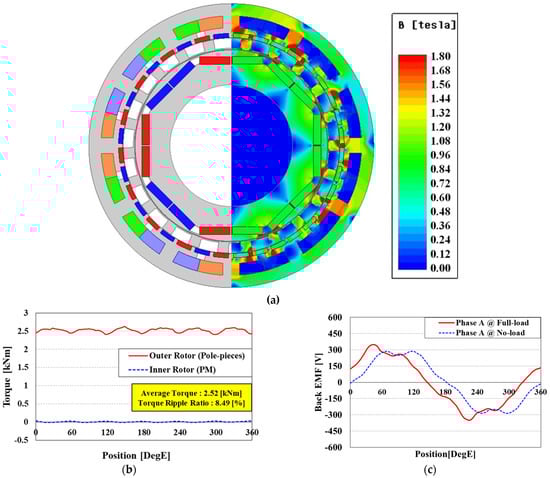
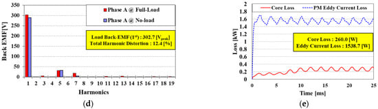
Figure 12.
Performance characteristics of the final design model: (a) 2D FEM model, (b) average torque at rated speed on full-load, (c) back-EMF waves at rated speed on no- and full-load, (d) back-EMF harmonics at rated speed on no- and full-load, and (e) core loss and PMs eddy current loss.
Table 5.
Specifications of induction motors for each railway vehicles in South Korea.
5. Conclusions
This paper was about the design of MG-PMSM for a high torque density of 45 kW–class tram. MG-PMSM has a structure in which a magnetic gear and a PMSM are integrated, and the power density is higher than that of the existing induction motor + mechanical gear. In addition, since a magnetic gear is used instead of a mechanical gear, it is advantageous in terms of working cycle and maintenance cost. In order to apply such MG-PMSM, this study presented the design process for this. First, the output characteristics of this motor varied greatly depending on the topology, and in the case of the tram, the mechanical coupling type was used in this paper because only one output is used in tram. Then, in order to find the optimal combination of the number of poles and pole-pieces, two equations considering the torque ripple coefficient and UMF were presented, and 8-inner rotor poles/22-pole pieces/36-outer rotor poles was selected. In addition, MG-PMSM designed a magnetic gear that satisfies the design constraints because torque is determined by this part. In particular, a new type of inner PM rotor was suggested because pieces in inner rotor cause permeance distortion of pole-pieces, and the outer PM and pole-piece angle were modified to maximize efficiency. Finally, an 2D MG-PMSM FEM model with 94% efficiency was derived by designing an appropriate stator part, which would improve torque density and efficiency compared to the existing driving system.
Author Contributions
Conceptualization, C.-B.P. and H.-W.L.; methodology, I.-H.J. and J.-H.L.; software, I.-H.J. and J.-H.L.; validation, J.L. and S.-H.K.; formal analysis, J.-H.L. and S.-H.K.; investigation, I.-H.J. and H.-W.L.; writing—original draft preparation, I.-H.J.; writing—review and editing, C.-B.P. and I.-H.J.; visualization, J.L. and J.-B.L.; supervision, C.-B.P. and J.L.; project administration, C.-B.P. and J.L.; funding acquisition, C.-B.P. and J.-B.L. All authors have read and agreed to the published version of the manuscript.
Funding
This work is supported by the Korea Agency for Infrastructure Technology Advancement (KAIA) grant funded by the Ministry of Land, Infrastructure and Transport (22RSCD-A163330-03) and by the National Research Foundation of Korea (NRF) grant funded by the Korea government (MIST) (No. 2021R1F1A1064291).
Institutional Review Board Statement
Not applicable.
Informed Consent Statement
Not applicable.
Conflicts of Interest
The authors declare no conflict of interest. The funders had no role in the design of the study; in the collection, analyses, or interpretation of data; in the writing of the manuscript; or in the decision to publish the results.
References
- Zhang, X.; Huang, Y.H. Influence of anti-kink system on curve negotiation performance of low-floor tram. Urban Rail Transit Res. 2018, 21, 111–116. [Google Scholar]
- Hondius, H. The development of low-flow trams. J. Adv. Transp. 1993, 27, 79–102. [Google Scholar] [CrossRef]
- Atallah, K.; Calverley, S.D.; Howe, D. Design, analysis and realization of a high-performance magnetic gear. IEE Proc. Electr. Power Appl. 2004, 151, 2. [Google Scholar] [CrossRef]
- Park, C.B.; Jeong, G. Performance verification of DR-PMSM for traction system according to permanent magnet shape. AIP Adv. 2020, 10, 025105. [Google Scholar] [CrossRef]
- Lim, J.-H.; Jeong, G.; Lee, H.-W.; Lee, J.-B.; Lim, J.-S.; Park, C.-B. Design and Analysis of the 45 kW-Class Magnetic Geared Permanent Magnet Synchronous Motor for Traction of Tram Vehicles. Appl. Sci. 2021, 11, 6360. [Google Scholar] [CrossRef]
- Atallah, K.; Howe, D. A novel high-performance magnetic gear. IEEE Trans. Magn. 2001, 37, 2844–2846. [Google Scholar] [CrossRef]
- Neves, C.G.C.; Filho, A.F.F. Magnetic Gearing Eletromagnetic Concepts. J. Microw. Optoelectron. Electromagn. Appl. 2017, 16, 1. [Google Scholar] [CrossRef][Green Version]
- Misron, N.; Mohd Saini, L.; Aris, I.; Vaithilingam, C.A.; Tsuyoshi, H. Simplified Design of Magnetic Gear by Considering the Maximum Transmission Torque Line. Appl. Sci. 2020, 10, 8581. [Google Scholar] [CrossRef]
- Cheng, M.; Sun, L.; Buja, G.; Song, L. Advanced Electrical Machines and Machine-Based Systems for Electric and Hybrid Vehicles. Energies 2015, 8, 9541–9564. [Google Scholar] [CrossRef]
- Zhao, H.; Liu, C.; Song, Z.; Liu, Z. A Consequent-Pole PM Magnetic-Geared Double-Rotor Machine With Flux-Weakening Ability for Hybrid Electric Vehicle Application. IEEE Trans. Magn. 2019, 55, 7. [Google Scholar] [CrossRef]
- Wang, Y.; Ho, S.L.; Fu, W.N.; Shen, J.X. A Novel Rotor Position Detection Method for Sensorless Control of Magnetic-Geared Permanent-Magnet Brushless Motor. IEEE Trans. Magn. 2013, 49, 7. [Google Scholar] [CrossRef]
- Sun, L.; Cheng, M.; Zhang, J.; Song, L. Analysis and Control of Complementary Magnetic-Geared Dual-Rotor Motor. IEEE Trans. Ind. Electron. 2016, 63, 11. [Google Scholar] [CrossRef]
- Shin, K.-H.; Cho, H.-W.; Kim, K.-H.; Hong, K.; Choi, J.-Y. Analytical Investigation of the On-Load Electromagnetic Performance of Magnetic-Geared Permanent-Magnet Machines. IEEE Trans. Magn. 2018, 54, 11. [Google Scholar] [CrossRef]
- Shin, H.; Chang, J. Comparison of Radial Force at Modulating Pieces in Coaxial Magnetic Gear and Magnetic Geared Machine. IEEE Trans. Magn. 2018, 54, 3. [Google Scholar] [CrossRef]
- Ito, K.; Nakamura, K. Investigation of Magnetic Interaction of IPM-Type Magnetic-Geared Motor. IEEE Trans. Magn. 2021, 57, 2. [Google Scholar] [CrossRef]
- Ren, X.; Li, D.; Qu, R.; Pei, T. Back EMF Harmonic Analysis of Permanent Magnet Magnetic Geared Machine. IEEE Trans. Magn. 2020, 67, 8. [Google Scholar] [CrossRef]
- Gerber, S.; Wang, R. Design and Evaluation of a Magnetically Geared PM Machine. IEEE Trans. Magn. 2015, 51, 8. [Google Scholar] [CrossRef]
- Zhang, X.; Liu, X.; Chen, Z. Investigation of Unbalanced Magnetic Force in Magnetic Geared Machine Using Analytical Methods. IEEE Trans. Magn. 2016, 52, 7. [Google Scholar] [CrossRef]
- Zhang, Y.; Lu, K.; Ye, Y. Permanent Magnet Eddy Current Loss Analysis of a Novel Motor Integrated Permanent Magnet Gear. IEEE Trans. Magn. 2012, 48, 11. [Google Scholar] [CrossRef]
- Zhu, Z.Q.; Liu, Y. Analysis of Air-Gap Field Modulation and Magnetic Gearing Effect in Fractional-Slot Concentrated-Winding Permanent-Magnet Synchronous Machines. IEEE Trans. Ind. Electron. 2018, 65, 3688–3698. [Google Scholar] [CrossRef]

Publisher’s Note: MDPI stays neutral with regard to jurisdictional claims in published maps and institutional affiliations. |
© 2022 by the authors. Licensee MDPI, Basel, Switzerland. This article is an open access article distributed under the terms and conditions of the Creative Commons Attribution (CC BY) license (https://creativecommons.org/licenses/by/4.0/).