1. Introduction
Induction motors have been used in manufacturing industries, household appliances, and recently, electric vehicles, because of their benefits in terms of cost, reliability, and simplicity of control [
1,
2]. Moreover, they work as a main mechanical power source; therefore, any fault of induction motors directly leads to a significant downtime of the entire system. The most frequent faults of induction motors are a winding insulation fault, a bearing fault, and a broken rotor bar. Among these faults, the winding insulation fault accounts for 21% to 40% of total failures in induction motors, depending on the specifications and rotor types [
3,
4,
5,
6,
7]. The occurrence rate of the winding insulation fault is high; moreover, it is one of the most severe faults, since it is accompanied by high fault current, heat generation, burned windings, burned motors, and in the worst case, fire hazard [
7].
The stator windings are multiple-wound copper wires in slots coated by a very thin insulation material, to avoid being short-circuited. However, this insulation material could be easily damaged in various operating environments. As a result, many stresses affect insulation aging in stator windings and insulation material. Thermal, electrical, ambient, and mechanical stresses account for most of the causes [
8,
9,
10,
11,
12,
13].
First, when the temperature of the stator windings is over a threshold temperature, oxidation occurs on the insulation material’s surface, making the insulation material brittle [
8,
9,
10]. Then, temperature stress leads to an expansion of the copper. Furthermore, under a rapid temperature rise on the winding, the copper conductor expands, damaging the coated insulation material, since the copper has a higher coefficient of thermal expansion than regular insulation [
12].
Second, there is electrical stress [
8,
9,
10]. The insulation aging is hardly affected by voltage stress of less than 1 kV. However, when inverter-fed drives operate machines, the inverter with pulse width modulation can invoke surge voltages on the motor winding. These surge voltages can destroy chemical bonds in the insulation of the stator.
Third, ambient stress encompasses multiple stress factors from the environment surrounding the motor windings [
10]. There are many factors in this regard, such as moisture, high humidity, oil from the bearing, and dirt from the environment. For example, if moisture or oil from the bearing is combined with dirty or carbon brush particles, it can create a conductive film at the insulation part.
Finally, there is mechanical stress, where the windings are directly affected by centrifugal and magnetic forces when motors operate [
11,
12]. The rotor windings of wound-rotor induction motors are exposed to high centrifugal force at high-speed drive. This force acts as the pressure between the windings and tends to crush the insulation. Except for the centrifugal force, high stator currents, which flow through the stator winding in the same stator slot, vibrate the windings. This magnetic force is proportional to the square of the stator current. When a motor is beginning its operation, a starting current is generally 5–10 times the rated current. Therefore, the magnetic force vibrates the windings, more than 25 times stronger, and can cause severe mechanical stress to the insulation of the windings [
12]. These four main factors are the so-called TEAM stresses [
13].
The winding insulation fault can be categorized into four types, as follows: inter-turn fault (ITF), open winding fault, phase-to-phase fault, and phase-to-ground fault. The ITF occurs when the stator wires lose their insulation performance in the slot and form a short circuit. Since the shorted circuit has a very low impedance, the high fault current can flow through the faulty winding. This fault current generates unwanted heat. As a result, fault spot expansion and an electrical fire could occur, due to the overheated windings. Except for the ITF, other winding faults invoke a large unbalance or circulating current; hence, they are easy to diagnose with adequate current signal measurement. Nevertheless, the ITF is very difficult to recognize, since its fault signal is very small, until severe enough to generate large heat and burned windings.
There are many studies on fault detection, diagnosis, and tolerant drive method to prevent fire hazards and reduce repair costs by the ITF [
14,
15,
16,
17,
18,
19,
20,
21,
22,
23,
24]. Conventionally, it is simple to diagnose ITFs, by using the motor current or extra sensor signal analysis. The motor current signal analysis and sequence component-based fault detection methods are typical and powerful [
14,
15,
16,
17,
18]. However, these methods are easily affected by the input grid voltage harmonics and unbalance components. Moreover, there are air gaps and external flux analysis methods for a sensitive fault diagnosis, using external flux sensors or an observer coil in machines [
19,
20]. The abovementioned methods are simple and powerful, but they have some limitations in establishing the fault criteria and demand for pre-experimental data. Consequently, to complement these issues, induction motor models with an ITF, such as the impedance model, winding function model, and the equivalent circuit model, have been studied by many researchers [
21,
25,
26,
27]. However, the impedance model in [
21] is valid only for offline tests, and the used models in [
25,
26,
27] can be inaccurate when applied to multipole motors, because they do not consider the distorted flux coupling in their models. In recent studies [
22,
23], the convolutional neural network (CNN) has been utilized in the development of an intelligent diagnostic tool. Furthermore, although some studies have been conducted on the ITF model, considering distorted flux coupling, these studies only apply to permanent magnet synchronous motors (PMSMs), not induction motors [
24,
28,
29]. Unlike in PMSMs, it is more complicated to derive rotor flux models of induction motors with ITF, due to distorted air gap fluxes by the nonuniform rotor current.
This paper presents a novel induction motor model with ITF, by describing every cross-coupling and distorted air gap flux distribution. Additionally, the rotor winding flux linkages are described in the independent DQ frame of every pole to describe distorted air gap flux effects. Hence, the rotor DQ current states are the pole number multiple of the conventional one. This fully described induction motor model specifically represents distorted air gap flux distribution and the nonuniform rotor DQ current by the ITF. However, the full model could be complex in the case of a high pole number induction motor. Furthermore, to reduce this full model complexity in the fault diagnosis, a simplified model is also proposed, with fewer rotor DQ current states. Finally, simulation and experiments are performed to verify the presented induction motor ITF fault models.
2. Induction Motor Model with ITF
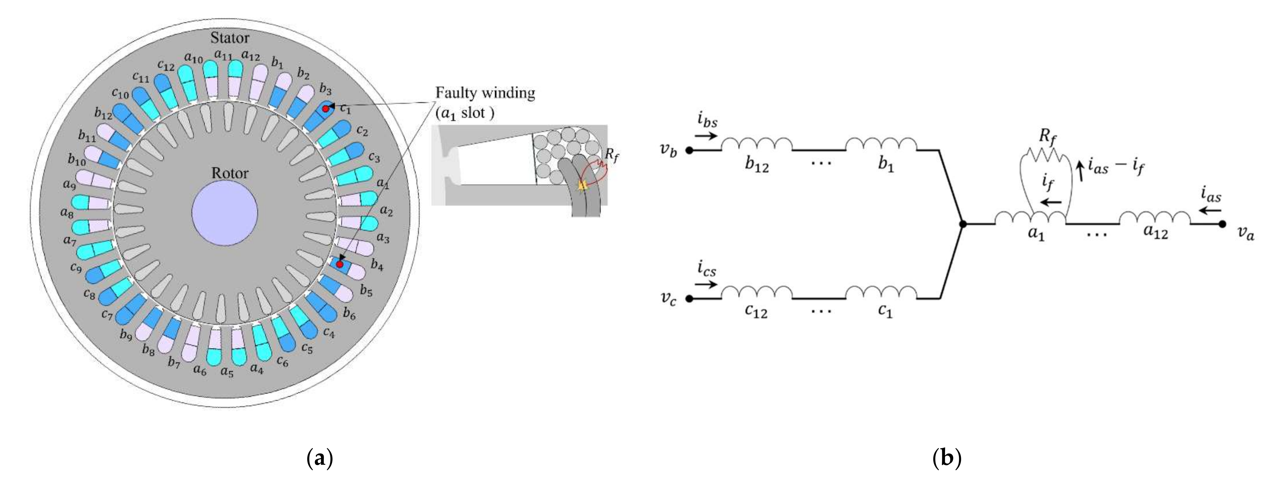
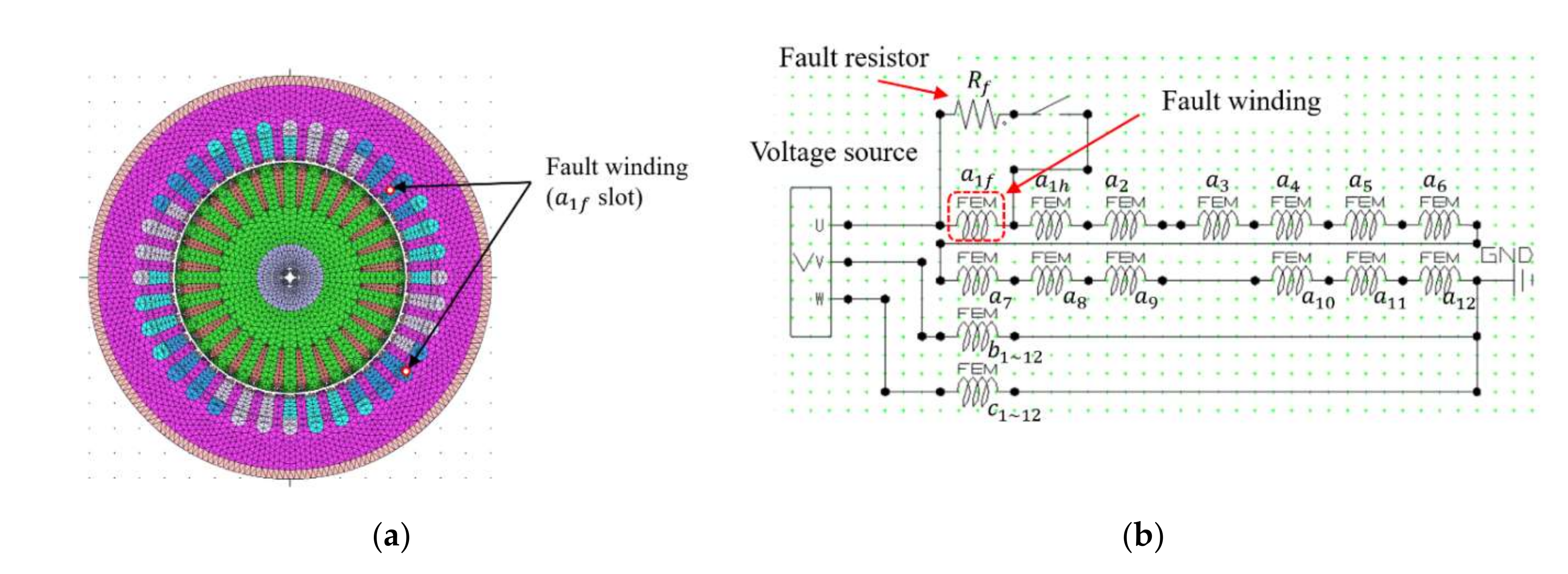
Figure 1a shows a three-phase 4-pole 36-slot induction motor, with distributed windings, and
Figure 1b shows the winding configuration with an ITF. Here,
,
, and
are 12 windings of each phase, and
and
denote the stator phase currents and voltages, respectively. We assumed that
winding has an ITF. The fault spot of
winding can be expressed as a closed loop, with a fault resistor
, since the neighboring windings that have lost their insulation are in contact with each other. In
Figure 1b,
denotes the fault current flowing through the closed loop.
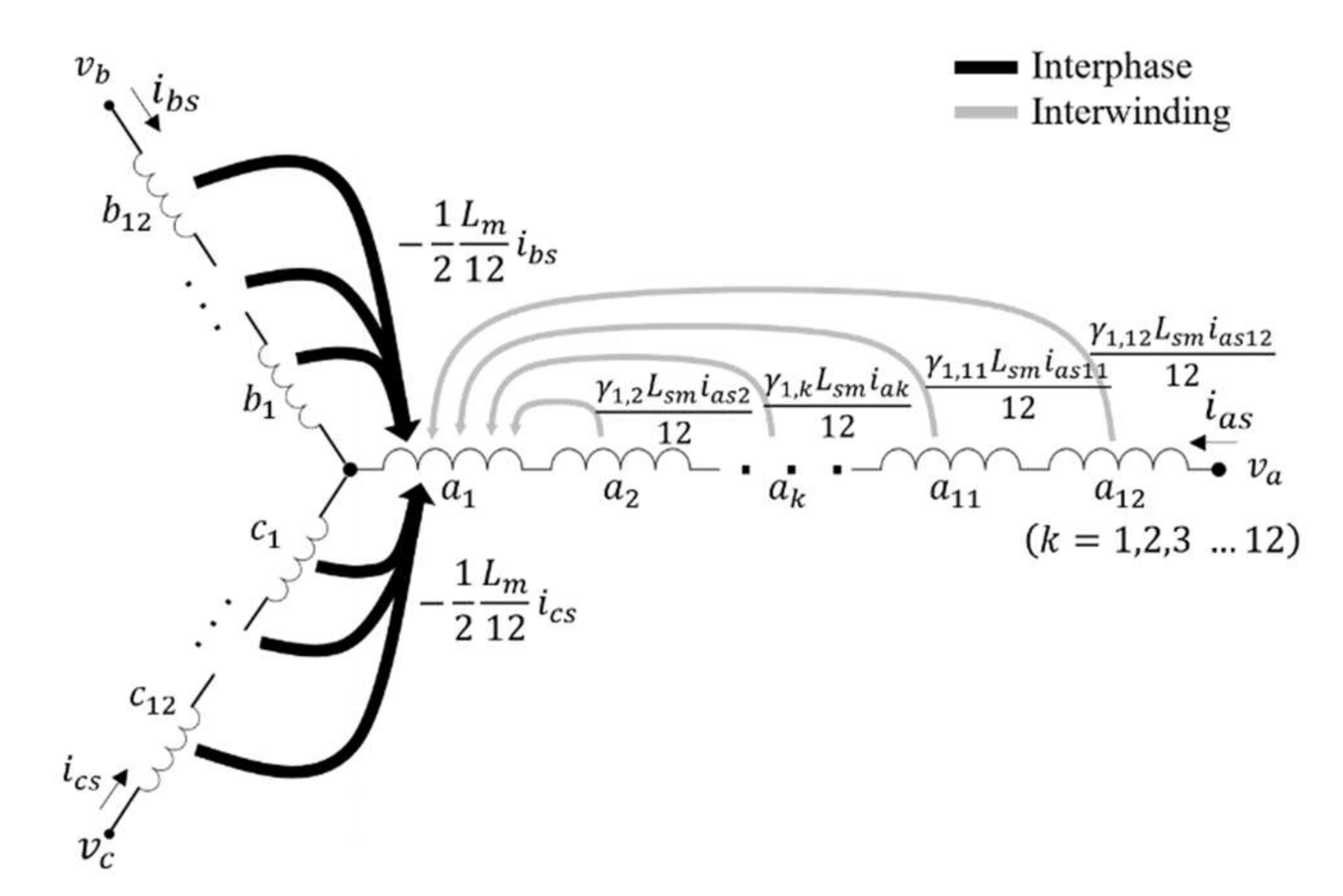
Under healthy conditions, every 12 windings of each phase conduct the identical phase current. Hence, it is not necessary to consider the mutual flux linkages between the same phase windings, since each phase self-inductance includes them. But, under the ITF, the faulty winding of conducts . Owing to the additional independent current state, it is essential to define flux coupling between the faulty winding and other healthy windings. Also, the mutual flux linkages between the faulty winding and the other phase windings need to be considered.
Figure 2 shows the inter-phase and inter-winding coupled flux linkages of the stator
winding, where
denotes the winding coupling factor [
27]. The black and gray lines show the inter-phase and inter-winding flux linkages. Since the inter-phase coupled flux linkages are almost evenly distributed to each
winding, the inter-phase mutual inductance of
winding and
- or
-phase winding can be expressed as
. Here,
and
n denote the phase self-inductance and number of windings per phase, respectively. Here,
n is 12. The winding coupling factor
explains the flux coupling effect, according to the flux distribution between inter-windings. The lower subscript numbers of
mean that the winding numbers affect each other. Therefore, the magnetic flux linkages of
winding, produced by the stator current, can be given as (1) with
where
and
denote the self and leakage inductance of one winding, respectively. Note that the total flux linkage of
winding is the sum of (1), by the stator current and the mutual flux linkage by the rotor current. The first and third term of (1) is inter-winding and inter-phase coupled flux linkage, respectively. Under a healthy condition, all the magnetic fluxes are evenly distributed to each winding. The magnetic flux of
winding is defined as (2) by dividing the
-phase flux
by
n.
From (1) and (2), the self-inductance of one slot winding can be obtained as (3).
where
is an accumulated stator coupling factor. Also, the leakage inductance of one winding satisfies
. The stator winding coupling factors
can be obtained using FEM simulation because these are determined by the winding arrangement.
With
, the entire
-phase flux linkage can be given in the following way, as:
, , and denote the flux linkages of , , and windings, respectively, and , , and denote the stator winding currents.
2.1. Stator Inductance Model with ITF
When an ITF occurs in
winding, the healthy turn ratio is defined as
, where
and
denote the number of turns of healthy and total windings, of one winding. A zero healthy turn ratio,
, denotes that all
winding has an ITF, and a unity,
, has no ITF. Under a healthy condition, the
-phase flux linkage by stator current can be obtained by calculating each winding flux linkage from (3) and (4), in the following way:
However, with the ITF,
is a sum of
and
which denote the healthy and faulty winding flux linkage. The
-phase flux linkage
and the faulty winding flux linkage
by stator current can be expressed in the following way, as:
where
,
,
,
,
and
denote the
-phase self-inductance and mutual inductance from a faulty winding.
and
are the faulty winding self-inductance and the mutual inductance from the healthy
-phase winding. Because self-inductances are proportional to the square of the number of turns,
which is the self-inductance of the faulty winding, is proportional to
and
.
denotes the mutual inductance between the healthy
-phase winding and faulty winding. The first term of
represents the mutual inductance between the healthy and the faulty winding of
, and the second term represents the does mutual inductance between
~
windings and the faulty winding. Since the
-phase flux linkage is the sum of the healthy winding flux linkage
and faulty winding flux linkage
,
and
include
and
of
, respectively. With (6), the three-phase flux linkages by the stator current and the fault current are obtained as (7) and (8).
where
.
For simplification, three-phase components are transformed into a stationary DQ frame by using Clarke transformation.
where
.
and denote the stator current in the stationary DQ frame. Since it is assumed that the ITF occurs in the winding, the q-axis flux and fault flux are orthogonal. Therefore, the mutual inductance between the q-axis and the faulty winding is zero.
2.2. Mutual Inductance between the Rotor and Stator Winding
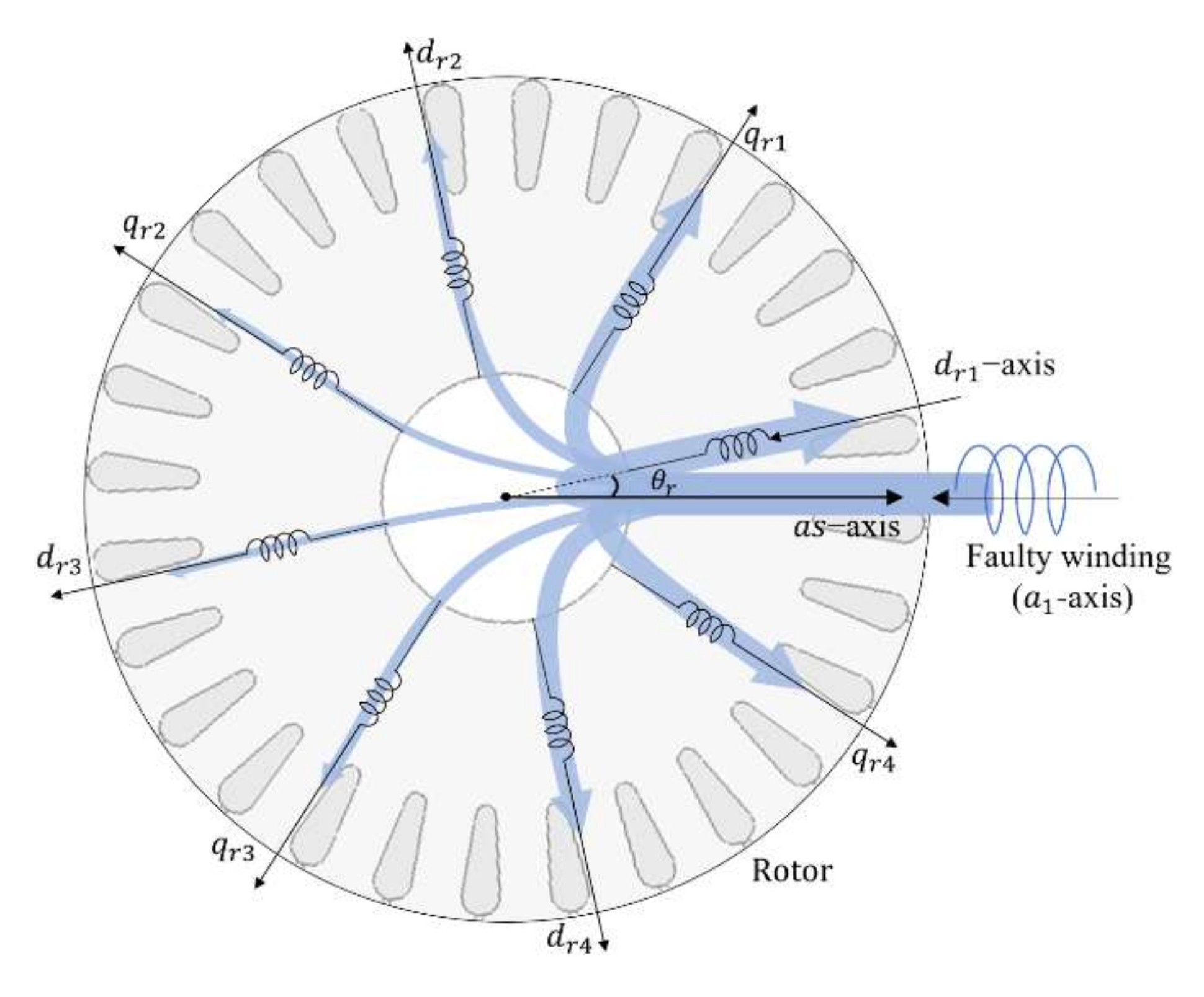
The rotor and stator winding fluxes are mutually affected. When the stator flux has a nonuniform flux distribution along the air gap by the faulty winding, the distorted component is reflected to the rotor flux linkage.
Figure 3 shows the rotor flux linkage by the fault current. As shown in
Figure 3, the mutual coupled flux linkage of the rotor winding with the faulty winding depends on the rotor position
in the multipole induction motor. To describe the coupled flux linkage distortion along the rotor position, the rotor DQ axes are subdivided into each single pole. Rotor axes are represented as
-axis in a rotor stationary reference frame.
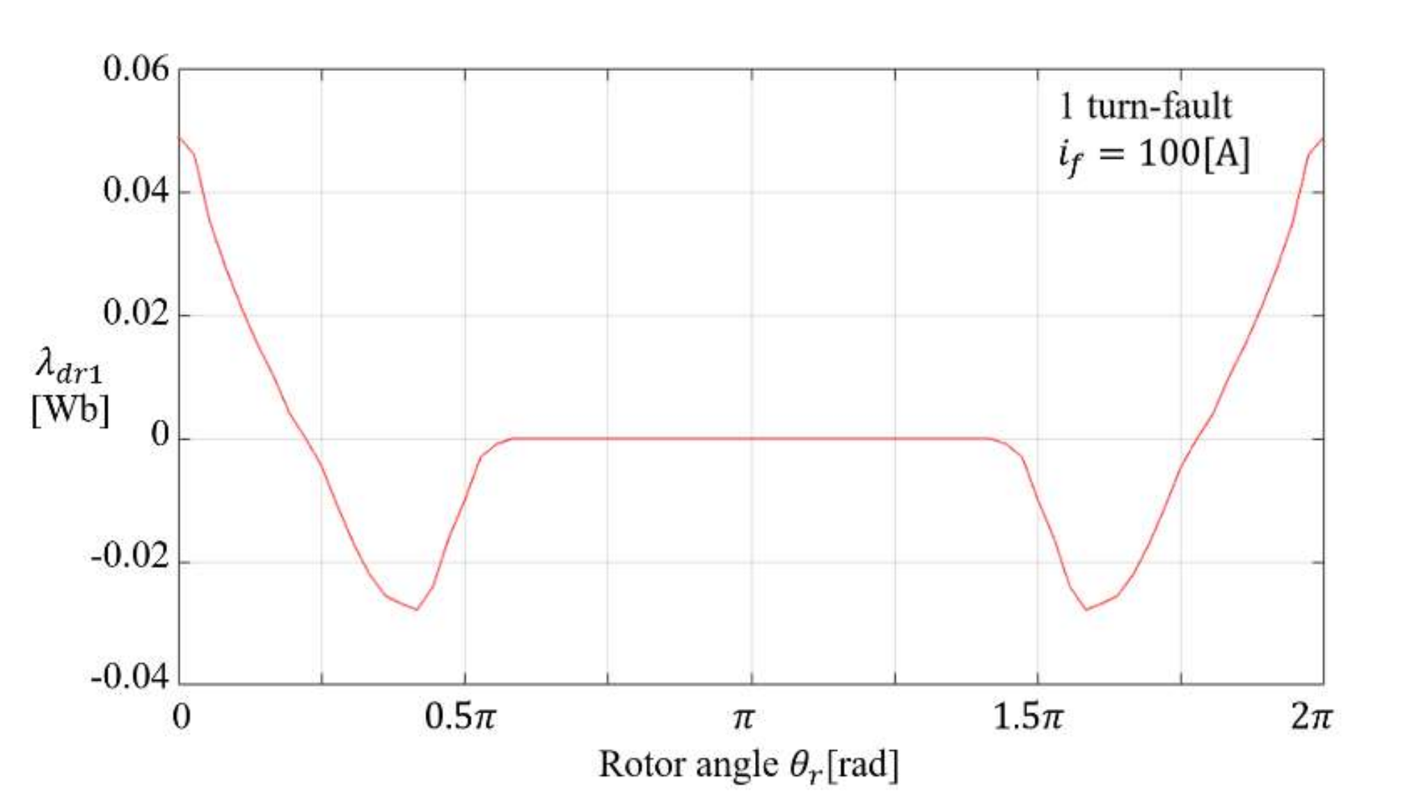
Figure 4 shows the lux linkage of the
-axis vs. the rotor position
from the FEM simulation results, when
, one turn ITF (
x = 14/15), and
for 4-pole induction motor, respectively. When
, the flux linkage
of
-axis has the maximum value, because
-axis rotor winding and the faulty winding directly face each other across the air gap. Since the mutual flux linkage is a periodic function of the rotor position, the mutual inductance between
-axis winding and the faulty winding can be presented using the Fourier series expansion.
denote the Fourier coefficients of the winding coupling factors between the rotor winding and the stator winding of one slot.
P is the number of each rotor physical pole.
The flux linkage from the rotor to the whole stator winding can be obtained regardless of the ITF, so these mutual inductances can be expressed simply.
Conversely, the flux linkage from the stator to the rotor should be separated into the healthy term and the fault term, because they are built with two different winding currents,
and
, so, the mutual inductances should also be expressed with the effect of the ITF, as follows (17)–(20).
The second terms on the right-hand side of (17) and (18) represent the effect of the ITF. However, in (19) and (20), since the rotor fluxes from the stator q-axis are hardly affected by the winding ITF, and can be expressed identically to (15) and (16), respectively.
2.3. Voltage Equation of Induction Motor with ITF
Based on inductances (9)–(20), the stator voltage equation of the 4-pole induction motor in a stationary d, q-axis reference frame can be obtained, as follows:
Based on inductances (9)–(20), the stator voltage equation of the 4-pole induction motor in a stationary d, q-axis reference frame can be obtained, as follows:
where
, ,
,
,
,
.
Here, the faulty winding is short-circuited, hence,
. The rotor voltage equation with the ITF can also be derived as (22).
where
,
, ,
and
denote rotor
-th winding voltages in the rotor stationary DQ frame.
and
denote the rotor resistance and rotor leakage inductance.
is the identity matrix, size 8. All the rotor bars are short-circuited by the end-rings, so rotor voltage is a null matrix:
. Because the rotor DQ axes are subdivided into pole number, rotor self-inductance
and rotor resistance
this should result in an 8
8 matrix function. By combining the stator and rotor voltage equations for the 4-pole induction motor, the full voltage equation of induction motor with the ITF can be represented as 11
11 matrix form, as follows:
where
,
When the proposed model is applied to the multipole induction motors, the voltage equation becomes a heavy calculation burden. Without the ITF, the rotor current satisfies and , therefore, the eight rotor currents will be reduced to two and (23) will be simplified.
Under the light ITF, the fault current is small and the rotor current distortion by the fault current would be small. For simplification of (23), it could be assumed
and
. With the assumptions, the rotor voltage Equation (22) can be simplified, as follows:
where
The simplified equation of induction motor with ITF can be represented as 5
5 matrix form in (25).
This simplified model can be adapted to multipole motors above 4-pole. However, when the severity of the machine is too high, the assumption is not satisfied, due to the flux distortion of the rotor, and the simplified model can lead to inaccurate results. Therefore, it can only be used for induction motors with a light ITF. The full and simplified models will be compared in the next section of model validation with experimental results.
3. Model Validation with Experimental Results
To utilize the presented ITF induction motor models for a fault analysis, flux coupling factors are obtained from the FEM simulation.
Figure 5a,b shows an FEM mesh model and stator circuit of the motor with the ITF. The parameters of the induction motor are listed in
Table 1. The a-phase winding is composed of twelve windings and the
-winding is divided into the healthy winding
and the fault winding
. To give a fault environment, the fault resistor
is connected to the
winding with the external switch. To estimate the stator winding coupling factors, firstly, every stator and rotor winding in the FEM circuit has to be opened. Secondly, direct current
should be injected into the
winding only, and then, the flux linkages of the
windings (
) are measured. From the measured fluxes, the stator winding coupling factors
are calculated, as follows:
By using the FEM simulation, the stator inter-winding coupling factors
can be obtained as (27).
The total stator inter-winding coupling factor
of the target motor was estimated as 36.295. In a similar way to the
estimation method, the stator–rotor coupling factors can also be obtained. From Fourier series expansion, the structurally dominant harmonic components are observed up to the
frequency of the fundamental frequency in this 4-pole machine. Hence, winding coupling factors are considered from the fundamental
to the
harmonics
. Rotor fault coupling factors are listed in
Table 2.
To validate the presented ITF induction motor models, experimental measurements were performed. The proposed model was simulated with MATLAB, by adapting the Runge–Kutta 4th method to the proposed fully described model (23) and simplified model (25). The parameters used in the model simulation and experiment are listed in
Table 1 and
Table 2.
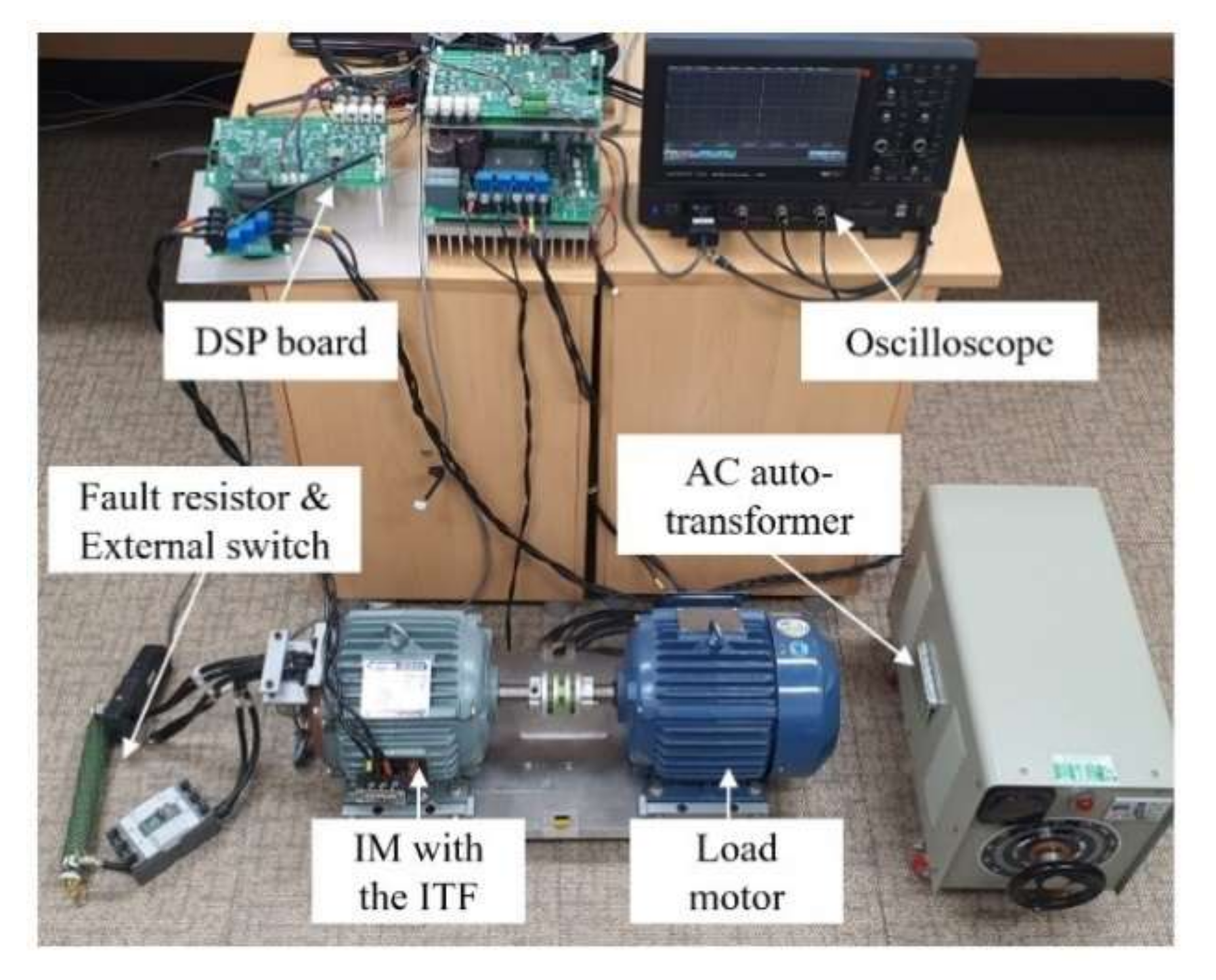
Figure 6 shows a picture of the experimental setup. The intermediate windings of the motor for the experiment were extracted through the back cover of the induction motor. The extracted windings were connected to the external switch and the fault resistor. The external switch was turned on to create the ITF condition. To reduce the high inrush start current, a variable AC autotransformer supplied a three-phase voltage to the motor. The supplied three-phase voltage is from the grid; it has harmonics and unbalanced components. For an accurate validation of the proposed model, the measured input three-phase voltages are used in the simulation.
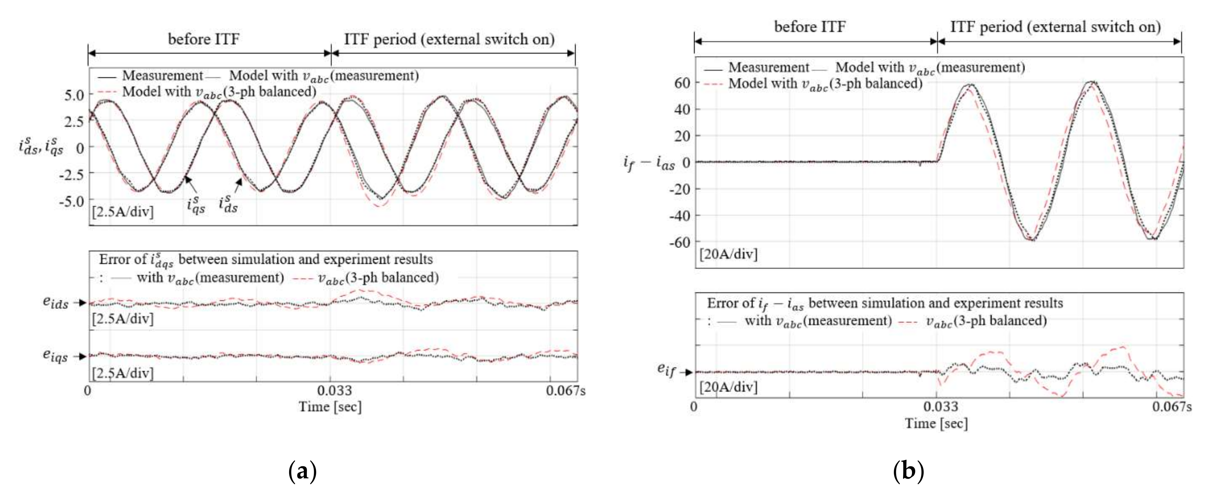
Figure 7 shows the simulation and experimental results of the D, Q-axis current in the stationary reference frame, and the fault resistor current, when the external switch is turned on at 0.033sec. The fault turn ratio
x and the fault resistance
are 0.667 and 0.1
, respectively. In the waveforms above
Figure 7a, the black solid line denotes the simply DQ transformed current from the measured phase currents. The black dotted lines and red dashed lines denote the calculated currents in the proposed model, with the measured and balanced three-phase voltage (380 Vrms, line-line, 60 Hz), respectively. In the waveforms below
Figure 7a,
denotes errors of D, Q-axis currents between the simulation with the proposed full model and experimental results. The black dotted lines denote the errors when measured grid voltage is used for simulation and red dashed lines denote the errors when the balanced three-phase voltage is used. Since there are harmonics (5th, 7th component: 0.09%, 0.90% of fundamental component) and negative sequence voltage (1.06% of the positive sequence component) in the real input grid voltage, these are reflected to the motor currents (5th: 0.20%, 7th: 1.21% and negative sequence: 5.23%), even before ITF occurs. When the ITF occurs,
has slightly bigger amplitude than
and the high fault resistor current
occurs, as shown in
Figure 7b.
denotes the error of the fault resistor current between the simulation with the full model and experimental results. As shown in
Figure 7, the motor stator and fault currents are almost identical between the simulation and experiment in a transient state, by observing
and
. By using the measured three-phase input voltage, the errors
and
are less than
0.4 A (9.1% of fundamental component) and
5.0 A (8.3% of fundamental component), respectively. However, when using the ideal balanced three-phase voltage, the current errors
and
are over
A (27.9% of fundamental component) and
.6 A (31% of fundamental component), respectively.
There are negative sequence current variations when the ITF occurs. This negative sequence current can be used as a fault signal for fault diagnosis, since it increases as the fault becomes increasingly severe. Hence, by analyzing the negative sequence current, the ITF can be diagnosed, and the fault severity can be identified.
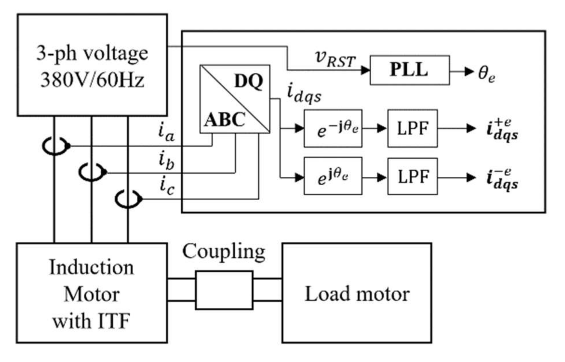
Figure 8 shows a block diagram of the negative sequence current extractor. Three-phase currents and voltages are measured, and the electrical angle
is calculated using phase-locked loop. Moreover, the measured three-phase currents are converted to the D, Q-axis currents in the positive and negative sequence frame, by multiplying
and
. By adopting the AC components with adequate filters, for example a low-pass filter, the positive sequence current
and negative sequence current
are obtained. As mentioned above, in the experimental environment, the negative sequence current can occur as a result of various causes, even without ITFs. The main factor generating unbalanced components with a healthy motor is the unbalanced input grid voltage. In the experimental results, the negative sequence current before the ITF
and the current after the ITF
were measured, and the difference was defined as a negative sequence current by the ITF, as
.
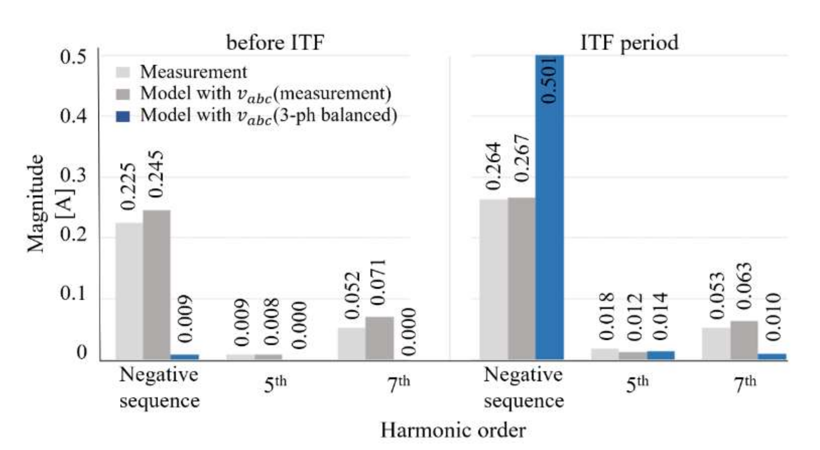
In
Figure 9, the magnitude of the negative sequence and harmonic currents (5th and 7th) of D, Q-axis currents
,
from
Figure 7a are presented. The left and right charts show the before and with ITF conditions. Before ITF, with the ideal balanced three-phase voltage, the model simulation results show almost zero negative sequence and harmonic current. However, with the measured input three-phase voltage, the model simulation results have a negative sequence current, 0.245, and harmonics (5th and 7th), 0.008 and 0.071, respectively. These are similar to the experimental results of 0.225, 0.009, and 0.052A, which are negative sequence 5th and 7th harmonic currents, in the absence of ITF.
In the ITF period, when a balanced input voltage is applied to the proposed model, the negative sequence current and harmonics (5th and 7th) are 0.501, 0.014, and 0.010, respectively. Here, the effect of the ITF is dominant in the negative sequence current generation. The proposed model simulation results, with the measured input grid voltage and experimental results, are negative sequence currents, 0.267A and 0.264A, 5th harmonic currents, 0.012 and 0.018, and 7th harmonic currents, 0.063 and 0.053, respectively. It seems that the negative sequence current is not affected by ITF. However, considering the phase of the negative sequence current, , of the simulation results with the measured input grid voltage and experimental results, these values are and , respectively. These complex numbers represent the ITF effect and are also of similar magnitude and phase. Even small input grid voltage harmonics and unbalanced components affect motor currents, hence the measured input voltages must apply the proposed model for the ITF diagnosis. With the measured input gird voltage, the proposed ITF model well represents the generation of harmonics (5th and 7th), as well as the negative sequence current.
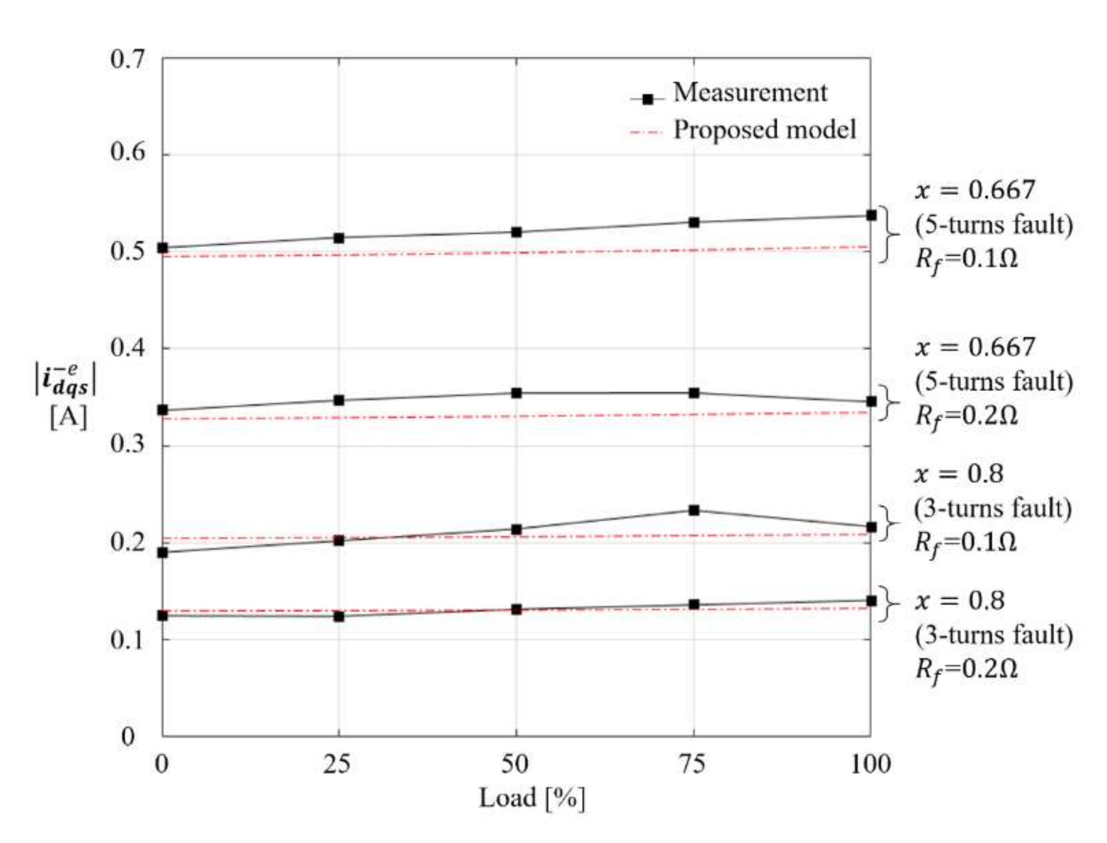
Figure 10 shows the negative sequence current, under various load conditions, with various ITF conditions. As the ITF severity increases, which means lower
and
, the magnitude of
increases. Furthermore, note that the negative sequence current of the ITF has little dependence on the load condition, as shown in
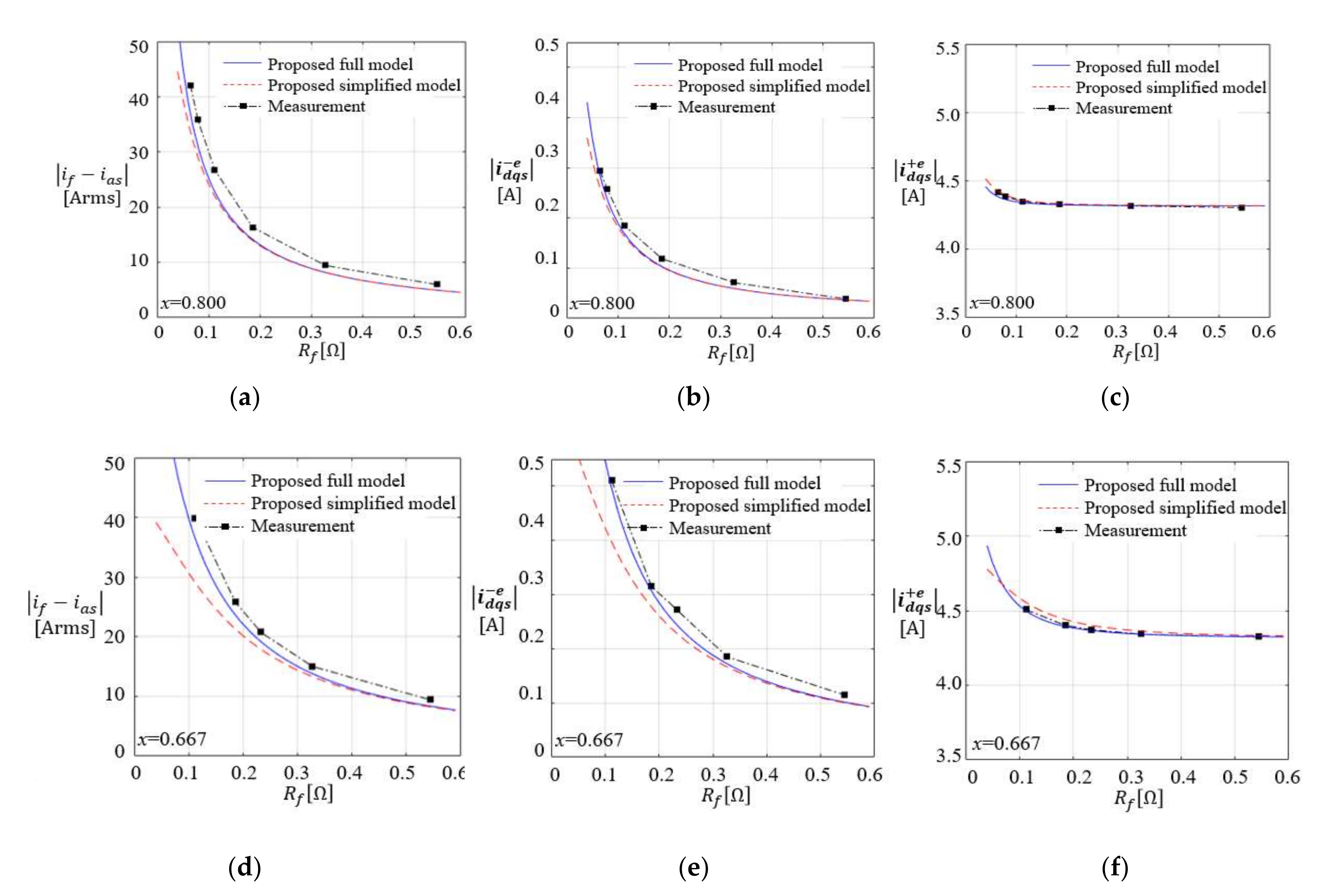
Figure 10. This means that if the negative sequence current by the ITF is used as a fault signal for a diagnosis, load information could be excluded. The simplified model and the full model were also proposed in
Section 2. To verify the feasibility of the two proposed models, the positive sequence current, negative sequence current, and fault currents are compared in
Figure 11. The simulations and experiments were implemented in various cases of fault, such as in the following:
and
. Due to the lack of dependency on the load condition, experiments and simulations were carried out under no load. At the constant healthy turn ratio 0.8 and 0.667, the negative sequence currents were analyzed with varying fault resistance. The blue solid lines and red dash lines denote the simulation results from the proposed full model and simplified model, respectively. The chain line connecting solid squares denotes the experimental results. As shown in
Figure 11a,d, the fault current increases when the fault resistance decreases, due to the decreased impedance of the fault closed-loop. The negative and positive sequence current also increases when the fault condition is much more severe, as shown in
Figure 11b,c,e,f. The simplified and full model have identical results for the light ITF, which has high
and
x. However, as the ITF gets worse, this increases. Here, when
x = 0.667,
= 0.112
, the error between the two proposed models occurred about 7.5%, as shown in
Figure 11d,e. Hence, the simplified model has an accuracy only for the light ITF.


