1. Introduction
Industrial fans are widely used in many applications, ranging from small units with a capacity of several kW, to large fans with a capacity of several MW. This group of machines ranks third in terms of energy consumption among all industrial devices, with an annual consumption of approximately 300 TWh of electricity [
1]. In 2013, the EU issued a directive on minimum requirements for electrically driven fans, which has been in force since 2013 [
2]. As a result of this, the saving of drive energy and improvement of efficiency have become primary drivers for this technology. Therefore, the market expects further development of existing fans in terms of efficiency [
3].
Centrifugal fans are machines that convert electrical energy into mechanical energy, which is used to drive the fan and then this energy is used for transport of the medium. During this process, losses occur which affect the efficiency of the fan. Efficiency losses are generated mainly when the medium flows through the fan.
There are two types of fans used in the industry:
centrifugal fans—these transport the medium by changing its direction in the radial impeller. Due to centrifugal force generated by the different velocity between the impeller inlet and outlet, this type of fan can generate a higher pressure rise compared to axial fans.
axial-flow fans—in this type of fan there is no change in the medium direction, which is transported by an impeller equipped with blades perpendicular to the fan shaft. This type of fan generates a lower pressure rise when compared to centrifugal fans.
In both types of fan, the ability to adjust flow parameters, with respect to flow rate or pressure change, is often required. In centrifugal fans, the most common method is the use of frequency inverters or throttles at the fan inlet that control fan rpm. The first method is efficient but expensive, due to the inverter cost, especially in large fans. The second method reduces fan efficiency significantly. Axial-flow fans can be controlled by use of the same methods as centrifugal fans. An additional method is the adjustment of impeller blades by rotating them along their longitudinal axis. It is an effective method of flow control ensuring a wide range of fan operation at high efficiency. There is no such method of control in centrifugal fans. This method of controlling the fan rotation speed is effective but costly. Another disadvantage is a few percent efficiency loss in the frequency inverter. In this control method, the resonance phenomena should be considered at the design stage to prevent potential failures when the excitation frequency (fan rpm, blade passing frequency) coincides with the natural frequency [
4] of the structure. There are two new methods of flow control of centrifugal fans which are based on change in the angle of the blade outlet [
5,
6]. However, this is still a developing technology with only a few instances of industrial application. These methods also need to take into account the problem of noise generated by centrifugal fans [
7,
8].
Bearing in mind the above advantages and disadvantages, new methods of controlling the flow parameters of centrifugal fans were sought, which would extend their effective range of operation and reduce installation costs. An additional goal was the use of innovative lightweight materials and processing methods that are intended to reduce fan component weight, and thus mass inertia, that are crucial in new methods of flow control. As a result, a unique centrifugal fan with variable length of impeller blades was designed.
The new concept presented in the paper has never been used in centrifugal fans. The main idea was to develop a new centrifugal fan flow control method based on the regulation system with features that extend the effective operating range of the fans. Such a new regulation system will improve the efficiency of centrifugal fans by better adapting their characteristics to temporary or variable operating conditions. The new system is designed to compete with centrifugal fans operating at variable speed as a result of use of frequency inverters.
The paper presents the development of understanding in the field of flow control, with respect to both theory and practice. The study concerns the solution of a scientific problem regarding the determination of the achievable range of high-efficiency fan operations with the use of variable blade lengths. For this purpose, in the first instance, numerical simulations (CFD) were used. Moreover, as part of the work, it was necessary to solve a technical problem, which was to ensure the technical feasibility of adjusting the length of the fan blade during its operation. To achieve this goal, computer-aided design tools were used, including numerical simulations with the use of FEM.
2. Materials and Methods
Two parameters describe the flow properties of centrifugal fans. These are the flow rate and fan pressure rise. The theory of centrifugal fan design describes the relationship between the dimensions of the fan impeller and these parameters. This relationship is presented below in the form of equations:
where:
V1—flow rate of fan with impeller of D1 outer diameter
V2—flow rate of fan with impeller of D2 outer diameter
Δp1—pressure rise of the fan with impeller of D1 outer diameter
Δp2—pressure rise of the fan with impeller of D2 outer diameter
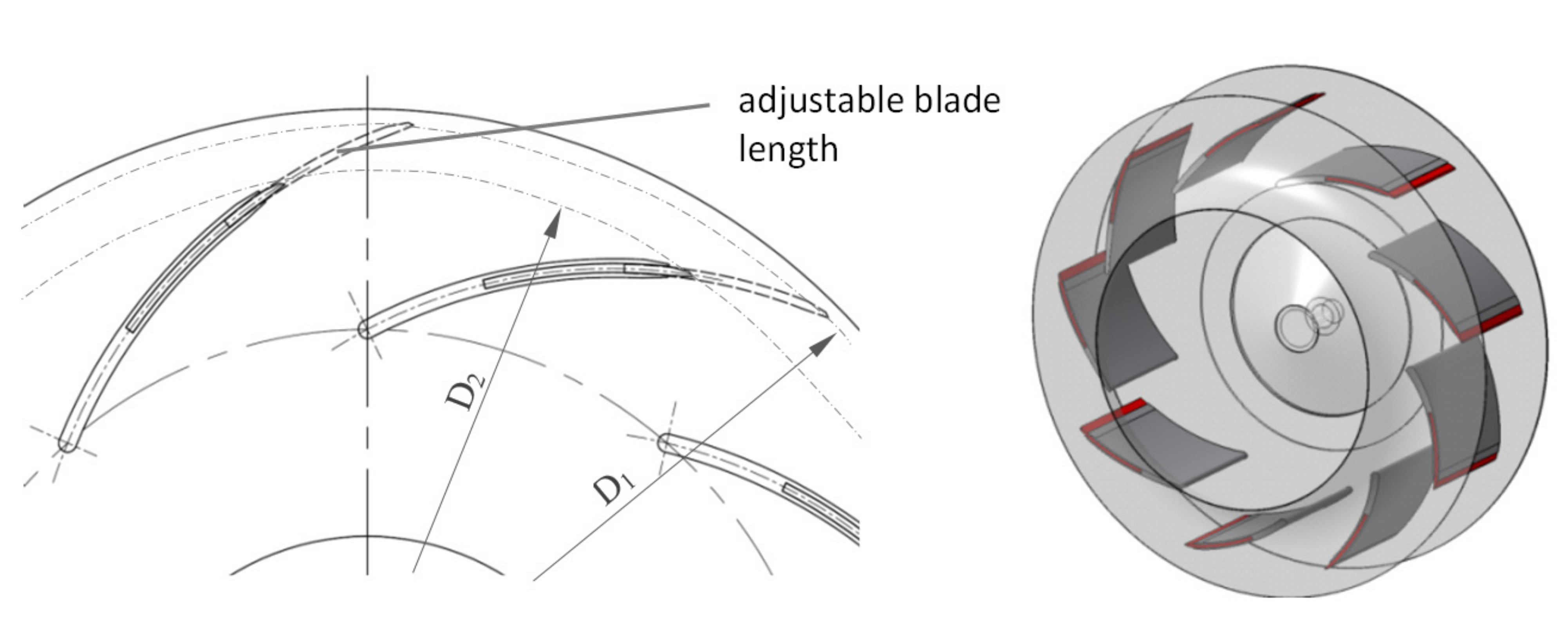
It is noted that there is a third-order relationship between the fan flow rate and the impeller outer diameter (1). Similarly, there is a second-order relationship between the pressure rise and the impeller external diameter (2). Based on the equations above, it can be seen that a relatively small change in the impeller diameter significantly affects the flow rate and the pressure rise of the fan. This observation led to the conclusion that it could be the basis for defining a new, effective method of controlling the flow parameters of centrifugal fans. This scientific basis led the authors to the idea of using variable length impeller blades to control the flow parameters of centrifugal fans. In the new method, the adjustable length of impeller blades enables modification of the external diameter, as shown in
Figure 1. For this purpose, the impeller blade is split into a fixed and a movable/adjustable blade.
During the development of the new solution, the technical problem of the control system for the position of the movable impeller blades needed to be solved. For this purpose, several concepts were developed, as shown in
Figure 2. On the basis of these, the final blade adjustment mechanisms were developed. The blade adjustment system is responsible for the synchronous movement of all moving blades. An additional difficulty was the development of a system that allowed the blades to move while the fan was running. The final solutions presented in this paper are subjects of patent applications.
There are three key factors to be considered when designing a fan with a movable blade flow control system:
identification of the operational range of the fan equipped with a new flow system control—for this purpose, numerical simulations are used, in which the efficiency and flow parameters are calculated,
simultaneous movement of the fan blades—the already mentioned important point which requires the design of an adjusting mechanism system that will ensure appropriate dynamic behavior of the impeller,
the inertia forces acting on the movable blade—because the movable blade is located near the outer diameter of the impeller, significant inertia forces occur. Therefore, it is important to use light, movable blades to prevent overloading of the adjustment mechanism system.
Results of investigations related to the above topics are presented in the following sections.
3. Numerical Efficiency Analysis
Preliminary numerical analysis of the fan was aimed at evaluating the operational range of fan performance curves in the case of an impeller with a movable blade. It required that, at minimum, fan characteristics in the middle, minimum possible and the maximum possible position of the blade were evaluated. As stated in the literature and standards, fan performance curves include, especially, a pressure curve, an efficiency curve and a power consumption curve in the determination of flow rate [
9,
10,
11,
12,
13,
14]. CFD calculation is an effective tool used to calculate turbo-machinery characteristics and flow fields within the flow domain [
11,
15,
16,
17,
18,
19,
20,
21].
3.1. Description of Model
The fan considered in the study was a centrifugal fan with an impeller of outer diameter D2basic = 810 mm. The preliminary assumption was to design an impeller with a movable blade to enable change of the impeller diameter from 0.9 to 1.1 fraction of D2basic, meaning that the minimal diameter was equal to D2min = 729 mm and the maximal diameter was equal to D2max = 891 mm. It was sufficient to evaluate fan operation in three positions only to identify the relevant parameters within which the fan could be operated.
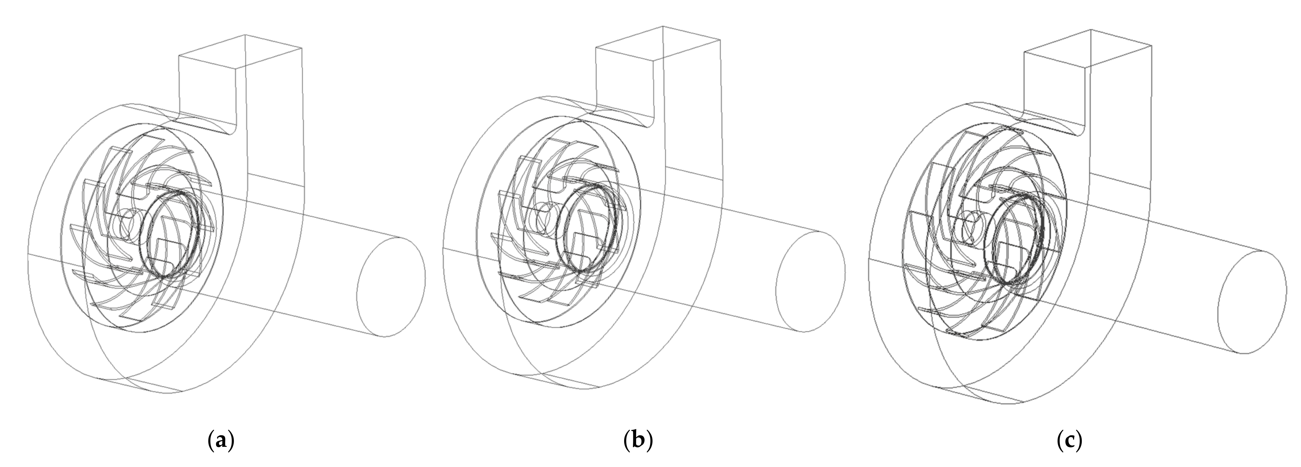
To perform the numerical CFD analysis, firstly a geometrical model of the fan with the impeller in three position was prepared (
Figure 3). In each case, the whole flow domain was divided into three parts: inlet zone, impeller rotating zone and outlet zone (fan volute zone). The calculation was performed using the “frozen rotor approach”, and suitable terms representing the centrifugal forces effect during impeller rotation with a rotational speed equal to 1500 rpm were added into the impeller domain [
22,
23,
24]. The mesh was created within each domain as a structural grid, in total numbering about five million elements, depending on the impeller size. A near wall treatment was introduced by boundary layer with first cell y+ value about 30. An exemplary generated mesh is shown in
Figure 4.
3.2. The Calculation Model
To derive fan performance curves, each model was calculated in six different working points which is sufficient for proper standardization [
9]. The CFD calculations were conducted using a turbulence two equations model k-ω (SST), in accordance with best practice for calculation of turbomachinery performance [
11,
15,
16,
17,
18,
19,
20,
21,
22,
23,
24]. For the inlet boundary condition, velocity was stated with respect to required volumetric flow. The outlet boundary condition was chosen as a pressure outlet with specified static pressure. All the simulations were carried out under the assumption that flow is incompressible, since the maximal pressure rise is about 3500 Pa. The density of air in the model was defined as 1.2 kg/m
3, in accordance with standard requirements [
9,
10].
3.3. Results of the Calculations
Each model was calculated until pressure rise and flow rates in any section converged, i.e., when further calculations did not change results significantly. As a result, the flow parameters, with respect to velocity, pressure distribution, streamline, etc., inside the fan, were obtained. From the point of view of the fan curves, the most important were the total pressure difference between the inlet and outlet of the fan and the required power on the impeller shaft. These values, in conjunction with volumetric flow rate, were used to calculate the efficiency of the fan. The fan performance curves are shown in
Figure 5.
The obtained results showed that a fan with a movable blade could be operated in a wider range in conjunction with relatively high efficiency. It was apparent, due to the type of centrifugal fan regulation, that a fan could be operated with an approximately 40% change of total pressure rise with an efficiency much higher than 70% at the same time. These results indicate the great potential of such solutions, but require to be verified on the real object.
4. Mechanism Models for Blade Adjustment
The mechanism responsible for controlling the geometry of the blades must meet two main criteria: to be light and to be able to operate during the rotation of the fan impeller. The first condition is important from the point of view of the efficiency of the device. Increasing the weight makes it necessary to use a more powerful motor, which translates into an increase in operating costs. The second negative effect is the increase in dynamic forces during operation; this may result in the need to use, for example, stiffer supports or a drive shaft with a larger diameter. Therefore, it is necessary to make the mechanism as light as possible, while maintaining the appropriate stiffness of the mechanism, which will ensure the repeatability of movement and transfer of the centrifugal forces during operation. The second condition is important due to the need also to change the geometry of the impeller during its operation (rotation). Designing a mechanism that allows change to the geometry only at standstill, limits the functionality of the described approach. The authors of the paper have developed several preliminary concepts of the mechanism. The paper presents the mechanism based on tie rods and a rope control system. These two were selected based on the possible applicability criterion. The following subsections present the idea of operation of each of those two.
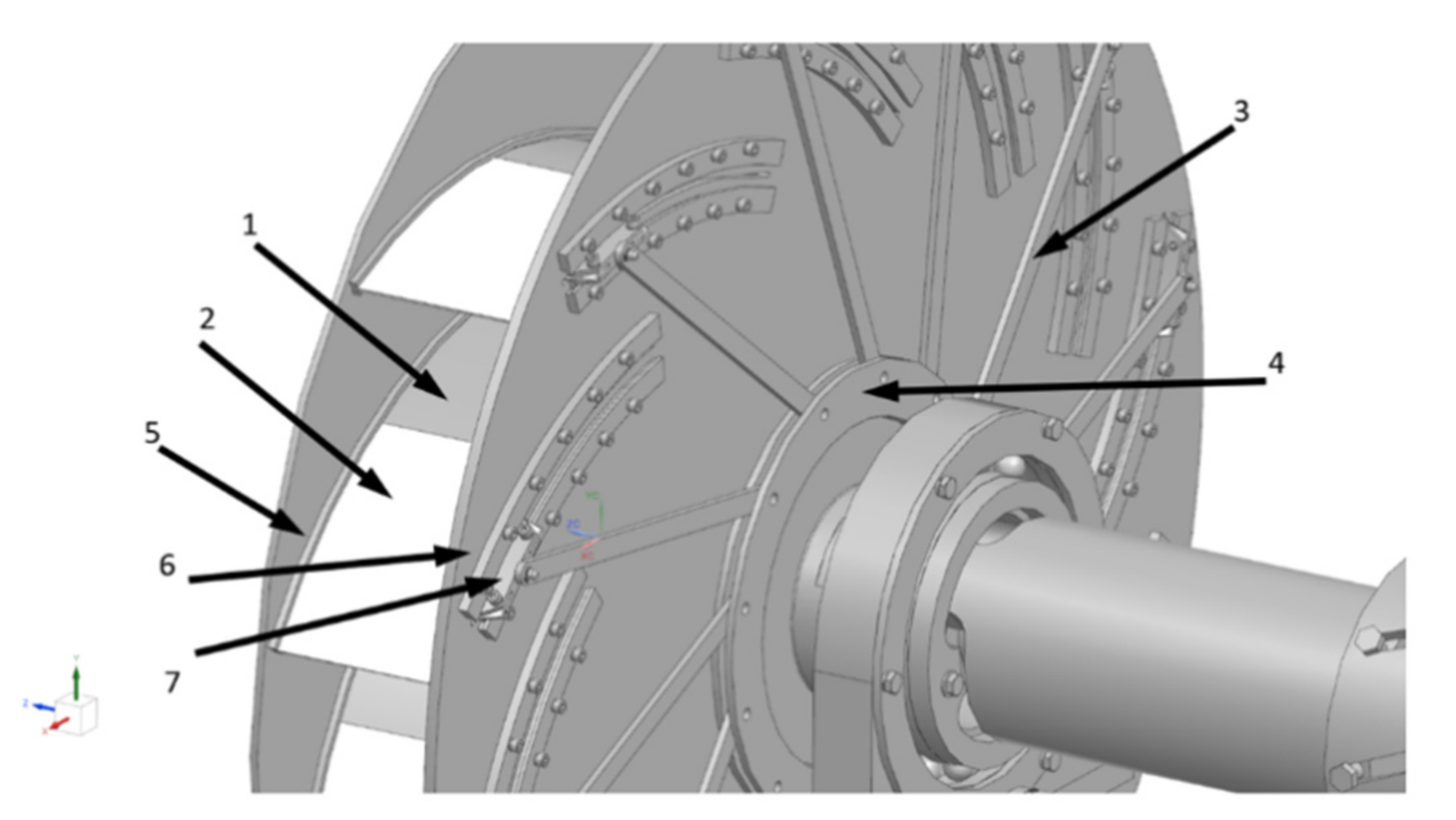
4.1. Tie Rods Mechanism
The idea of the presented solution shown in
Figure 6 and
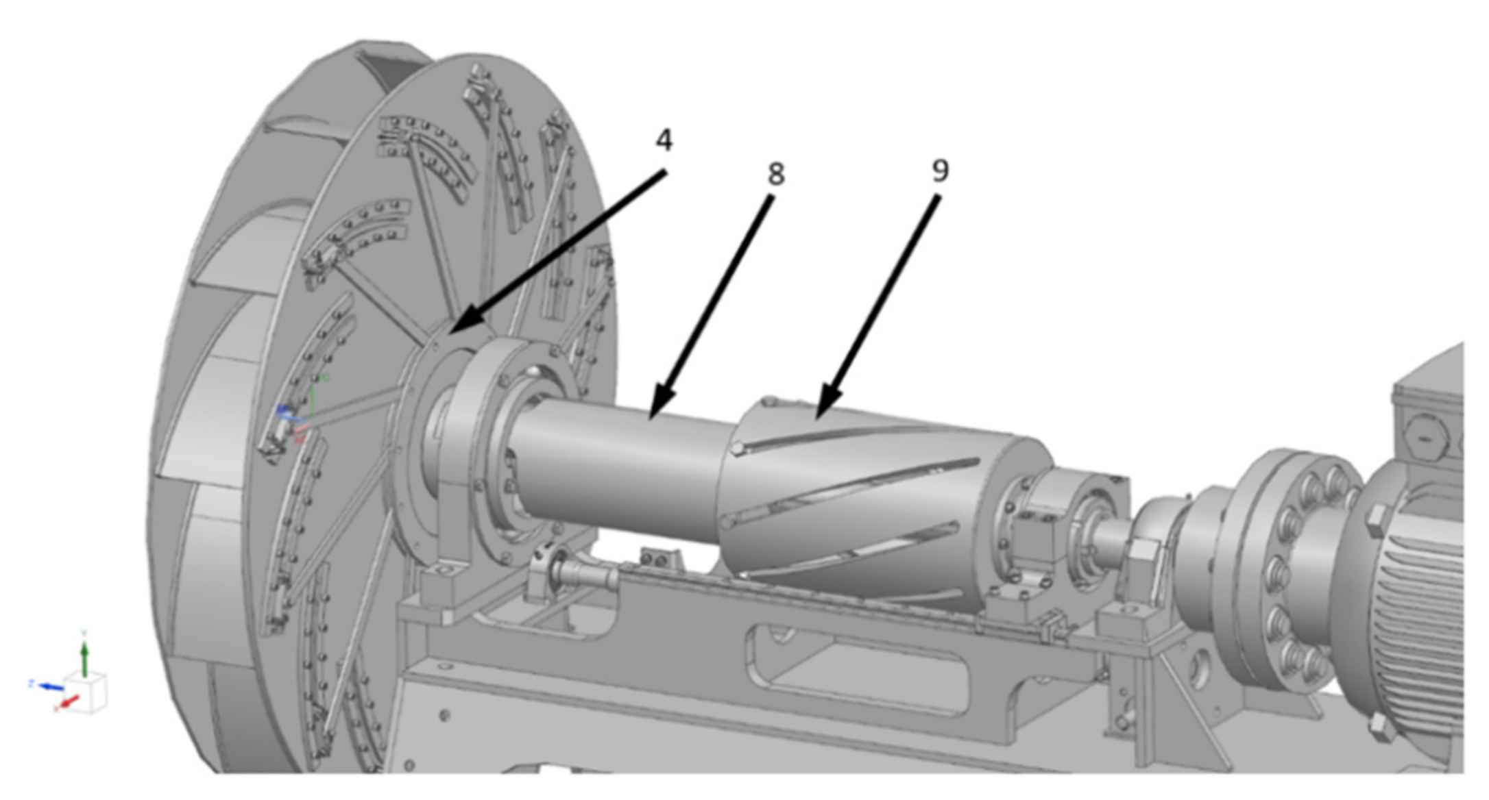
Figure 7 is to force the movement of the movable blade (item 2) by the tie rod system (item 3). Their number is determined by the number of impeller blades. The ties are set in motion by turning a special disc (item 4). Through this movement, the movable part of the blade moves along its fixed part (item 1). The blade guidance is carried out by two different guides: 1D (item 5) and 2D (item 6). The movable part of the blade is fixed in a slider (item 7) that moves between the 2D guides. The rotation of the disc is forced by the connector (item 8), which is rotated by movement of the element that converts the sliding motion to rotating motion (item 9). Inside these elements, the fan drive shaft rotates all the time. Because item 9 moves along the drive shaft, it is possible to change the geometry of the rotor during operation. The entire tie rods control mechanism is presented in
Figure 7.
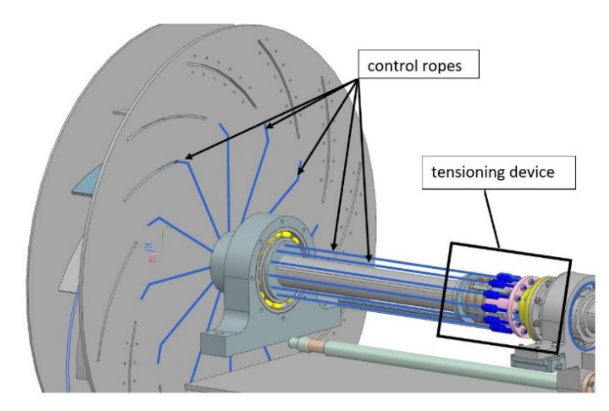
4.2. Rope Control System
The rope control system, in contrast to other solutions, uses centrifugal force as the main force activating the movement of the blade. The rope control system role is to counteract the centrifugal force causing the movement of blades in the radial direction towards the fan external diameter. Due to this, system operation is possible only during fan rotation. The main position of the blades is controlled by the main sliding collar, which is similar to the tie rods solution. However, because the tension in the ropes is generated by the pulling blades, an additional tensioning device was designed. Its task is to keep tension in the control ropes even when the fan is not rotating. As the centrifugal forces are relatively high, the Dyneema
® rope SK-75 (Ø
rope = 1.5 mm) was selected for the system. Apart from its great strength, it is characterized by low elongation (up to 3.5%) and high resistance to many chemicals, which makes it an excellent choice for the industrial environment.
Figure 8 and
Figure 9 present a general view of the concept and the tensioning device, respectively.
5. Blade Design in Detail (Strength Analysis)
To compensate for the additional weight of the blade adjustment mechanism, the use of innovative lightweight materials and processing methods for blade manufacturing is necessary. By reducing the resulting centrifugal forces and mass inertias, the elements and links of the adjustment mechanism can be produced in smaller dimensions, resulting in a decrease in the dynamics of the entire system.
Based on design calculations for the entire fan system, it was determined that the target weight of a single blade with the given design must be less than 350 g, ensuring appropriate strength of the whole system. For installation space reasons, the maximum blade thickness was also limited to 5 mm. Two general approaches were used to achieve the weight target. Firstly, two high performance metallic blade materials (
Table 1), which can be processed conventionally, were investigated. Secondly, the potential of composite materials (e.g., fiber-reinforced plastic) needed to be demonstrated. Based on these restrictions and the additional boundary conditions shown in
Table 2. FE models were set up in ANSYS for each variant and mechanism.
5.1. Variant 1—Metal Blade Design
The blade design for the tie rod mechanism consists mainly of two components (
Figure 10a, left): a contoured blank with a lateral lace and a solid mounting bracket attached to it as a connector for the adjustment mechanism. In contrast to this, for the rope mechanism (
Figure 10b), a simple rectangular blank is used, with an attached U-shaped steel sheet at its inner end, which serves as a lead-through and force introduction element for the Dyneema
® rope ensuring blade adjustment. In both concepts, the blades are guided in the lateral area by guiding rails (not shown).
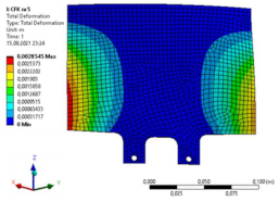
The FE simulation showed relatively quickly that the use of steel as blade material was unsuitable for the tie rod mechanism. At a sheet thickness of 4 mm, there was a deflection at the blade end of approximately 1.7 mm and an equivalent v-Mises stress in the radius range of the lace of approximately 690 MPa. Together with the mass of 690 g for one single blade and the tolerable stresses, this led to the disqualification of the steel variant. The best compromise between weight reduction and deflection was reached with the high strength aluminum blade at 2 mm sheet thickness. For this variant the max. v. Mises stress was approximately 350 MPa (
Figure 11a) at a deflection of approximately 3.2 mm at the blade end. Together with the mass of only 123 g for one single blade, the aluminum design was preferred for further investigation and also used as the principal blade material for the rope mechanism design.
Since no material models were available for the flexible Dyneema
® rope, the contact zone of the rope with the U-shaped steel sheet was represented by spring elements with a stiffness of 1 kN/mm (
Figure 11b). The rope itself was not part of the FE model. The evaluation of the v. Mises stress showed that the most stressed area, with approx. 330 MPa, was the edge area of rope lead through.
To avoid plastic deformation, or even failure, during operation, steel materials with a correspondingly high yield strength and good formability must be selected for this part of the blade. In addition to dual-phase steels (such as the previously mentioned DP600), super ductile TWIP or TRIP steels, which harden by forming, are particularly suitable for such applications. Twinning-induced plasticity (TWIP) and transformation-induced plasticity (TRIP) steels are characterized by high tensile strength up to 1.1 GPa (higher in TRIP steels) and elongation up to 100% (TWIP), which ensures good formability. They have an austenite structure, which is obtained by using a high level of manganese. In TRIP steels, the austenite structure is not stable under mechanical load which leads to martensite phase transformation and a high work hardening rate. In TWIP steels, the predominant mechanism is twinning without any phase transformation. In addition to the strength of the materials used, the possible wear of the rope, due to the relative movement of the contact partners during blade adjustment, plays a role that should not be neglected. In further investigations, it requires to be established how the rope can be protected against damage and how safe operation can be ensured over the entire lifetime of the fan.
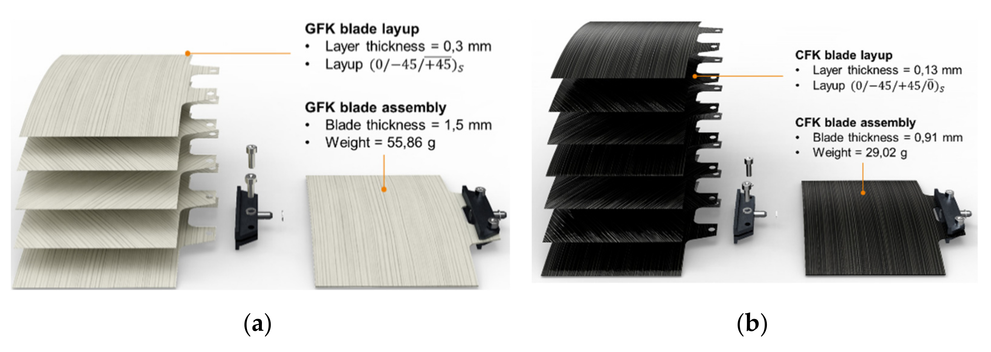
5.2. Variant 2—Composite Blade Design
For the tie rods mechanism, two composite variants concepts were created: glass-fiber-reinforced plastic (GFRP) and carbon-fiber-reinforced plastic (CFRP) made of continuous fiber-reinforced prepregs. The mechanical properties are shown in
Table 3.
Figure 12 shows the final composite blade concepts. The GFRP variant with a layup
, blade thickness = 1.5 mm and weight = 55.86 g. The CFRP variant with a layup
, blade thickness = 0.91 mm and weight = 29.02 g.
Five different layer configurations were simulated [
22,
25]. The FE simulation demonstrated that the layer structure number five showed the best results for both variants (
Table 4 and
Table 5); for the GFRP variant 3.17 mm and for the CFRP variant 2.85 mm.
6. Discussion
The new method of regulating the flow parameters of centrifugal fans required the development of a special technical solution that would allow the moving part of the blade to be moved along the fixed part. Since the moving blade is located close to the outer diameter of the impeller, significant inertial forces occur. Therefore, the mass of the movable part of the blade is very important from the point of view of the loads occurring in the control system. As part of the work presented in this article, two solutions controlling the position of the movable part of the blade were developed. These solutions use a system of rigid links and special Dyneema
® ropes, which are controlled by the rotation (variant with rigid links) or displacement (for Dyneema
® ropes) of the control element on the fan shaft. FEM simulation tools were used to develop these solutions in detail. Such simulation tools play an important role in numerical research [
26,
27]. The use of Dyneema
® ropes to adjust the position of the blades presents great opportunities in terms of weight and installation space savings. However, the simulation results showed a high edge load in the corner area of the movable blades, where the rope changes direction by 90 degrees. This local stress, combined with the frictional effect, is likely to have a negative effect on the durability of the rope. Rope friction due to contact with other elements should be prevented as much as possible and the rope must be significantly oversized to ensure safe operation. This aspect should be considered in more detail in further research.
As mentioned, the mass of the movable part of the blade has a significant effect on the control system that controls its position. The results of simulations show that the use of lightweight materials with high strength, such as, for example, 6000 series aluminum, for the moving part of the blade is desirable. The use of steel for this part of the blade causes large centrifugal forces, which require a significant and costly adjustment mechanism. Considering the above conclusions, the possibility of using composite materials for the movable part of the blade was also analyzed. Two material variants were used: glass-fiber-reinforced plastic (GFRP) and carbon-fiber-reinforced plastic (CFRP) made of continuous fiber reinforced prepregs. The idea behind the solution was to enable the interchangeable use of metallic and composite movable blades in the existing control mechanism housing. The criterion for assessing the composite variant was primarily its deformation, which may cause the blades to stick in the guides and within the available space in the rotor. The carbon-fiber-reinforced plastic variant turned out to be a better solution. The big advantage of using composite materials is the low mass of the movable blade, which for this variant was 29 g, while the variant made of 6000 series aluminum weighed 117 g with almost the same stiffness properties.
A fan with a developed regulation system requires the use of an independent shaft on which the impeller and part of the regulation system are mounted. The shaft has its own bearings and is connected with the drive motor with the use of a coupling. Fans with lower power, up to about several dozen kilowatts, usually use the direct mounting of the impeller on the motor shaft. For larger fans, an independent shaft is typically used, which is mainly due to large rotating masses that cannot be directly seated on the motor shaft. For this reason, the developed solution is appropriate for larger fans.
At this point the efficiency can be understood more broadly. The one undoubted efficiency is that of the fan itself. In
Figure 5, it is shown that the fan operates efficiently in a range of three different characteristics. So, the efficient operational range of one fan was extended three times. However, understanding the efficiency of the presented solution more generally, as part of a bigger system, efficiency is improved: in time (production of only one unit), in space (installation of only one unit), and in terms of costs (one unit instead of three or a unit equipped with a costly inverter). As the solution is new, it requires time to implement in everyday applications, but it has great potential to be part of a new generation of efficient ventilation systems.
7. Conclusions
Changing the outer diameter of the blades of the radial fan impeller allows for effective control of its flow parameters in a much wider range than in traditional solutions of fans with a fixed diameter. To enable this adjustment, the rotor blade has been split into a fixed part, located closer to the rotor axis, and a movable part that moves along the fixed part. In this way, it is possible to adjust the outer diameter of the rotor. To evaluate this concept of regulation in detail, verification analyses were carried out with the use of analytical and simulation methods. The results of the numerical flow calculation CFD indicate that, due to this type of centrifugal fan control, it will be able to operate with approximately 40% greater change in total pressure increase and with an efficiency above 70%, while maintaining a constant rotational speed of the impeller. Such parameters were obtained assuming that the length of the movable blade is about 30% of the length of the fixed blade. As presented in the obtained charts of fan performance (
Figure 5), it was shown that it is possible to change and control the characteristics of the in-operation centrifugal fan with no change of the operational rotational velocity.
The results suggest great potential for such a solution and in many cases allow the resignation of a regulation method by use of a frequency inverter and variable rotational speed. This lowers the construction costs of fans, especially those with higher power, where the cost of the inverter is significant. In addition, efficiency losses that occur during the inverter operation are also eliminated. The concept presented in the article has been tested mainly with the use of advanced computational and simulation tools. Currently, the authors are conducting research on the first experimental prototype of a fan equipped with a new system for regulating flow parameters. The results of the experimental tests of the new fan will be presented in a separate article, after all experiments are completed.
8. Patents
Solutions enabling the adjustment of the position of the moving part of the blades have been submitted as patent applications (P439436, P439438, P439439). Three variants of the control system have been developed that can be used in centrifugal fans.
Author Contributions
Conceptualization, P.M., P.O., D.P., J.W., P.S. and T.O.; methodology, P.M., P.O., D.P., J.W., P.S. and T.O.; software, P.M., P.O., D.P., J.W., P.S., M.D., T.O. and T.T.; validation, P.M., P.O., D.P., J.W., P.S., M.D., T.O. and T.T.; formal analysis, P.M., P.O., D.P., J.W., P.S., M.D., T.O. and T.T.; investigation, P.M., P.O., D.P., J.W., P.S., M.D., T.O. and T.T.; resources, P.M., P.S. and T.O.; data curation, P.M., P.S., T.O. and L.K.; writing—original draft preparation, P.M., P.O., D.P., J.W., P.S. and T.O.; writing—review and editing, P.M., P.O., D.P., J.W., P.S. and T.O.; visualization, P.M., P.O., D.P., J.W., P.S. and T.O.; supervision, L.K. and P.M.; project administration, P.M., T.O., P.S. and J.W.; funding acquisition, L.K., P.M., T.O., P.S. and J.W. All authors have read and agreed to the published version of the manuscript.
Funding
National Centre of Research and Development, Grant No. CORNET/26/2019. German Federation of Industrial Research Associations (AiF) Grant No. CORNET: 253 EBR.
Institutional Review Board Statement
Not applicable.
Informed Consent Statement
Not applicable.
Data Availability Statement
Not applicable.
Conflicts of Interest
The authors declare no conflict of interest.
References
- Ecodesign Fan Review—Review Study of Commission Regulation (EU) No 327/2011, Final Report; 2015, European Commission Report. Available online: https://www.eceee.org/static/media/uploads/site-2/ecodesign/final_report_fan_review_-_16_mar_2015.pdf (accessed on 15 January 2022).
- EUROPEAN COMMISSION REGULATION (EU) No. 327/2011 of 30 March 2011. Available online: https://www.eup-network.de/fileadmin/user_upload/Produktgruppen/Lots/Ventilatoren_Verordnung_110604.pdf (accessed on 15 January 2022).
- Jae-Sub Ko, J.H. Improvement of energy efficiency and control performance of cooling system fan applied to Industry 4.0 data center. Electronics 2019, 8, 582. [Google Scholar] [CrossRef] [Green Version]
- Rusiński, E.; Moczko, P.; Odyjas, P.; Pietrusiak, D. Investigation of vibrations of a main centrifugal fan used in mine ventilation. Arch. Civ. Mech. Eng. 2014, 14, 569–579. [Google Scholar] [CrossRef]
- VIBROSON ŁÓDŹ DR INŻ. A. PODSĘDKOWSKI SPÓŁKA Z OGRANICZONĄ ODPOWIEDZIALNOŚCIĄ, Łódź, PL. Centrifugal Fan with a New System of Setting the Angle of the Impeller’s Blades During Movement. Patent Poland P.406973.
- VIBROSON ŁÓDŹ SPÓŁKA Z OGRANICZONĄ ODPOWIEDZIALNOŚCIĄ, Łódź, PL. Centrifugal Fan with Variable Rotor Geometry during Operation. Patent Poland P.418821.
- Qi, D.; Mao, Y.; Liu Xi Yuan, M. Experimental study on the noise reduction of an industrial forward-curved blades centrifugal fan. Appl. Acoust. 2009, 70, 1041–1050. [Google Scholar]
- Lia, S.; Wang, W.; Liu, Q.; Li, X. Validation of numerical prediction method of BPF noise for industrial centrifugal fans. HVAC R Res. 2014, 20, 435–443. [Google Scholar] [CrossRef]
- Standardization: EN ISO 5801:2008; Industrial Fans—Performance Testing Using Standardized Airways. British Standards Institution: London, UK, 2008.
- Standardization: DIN 24163-1 (1985-01); Ventilatoren—Leistungsmessung—Normkennlinien. 1985. Available online: https://www.beuth.de/de/norm/din-24163-1/1172149 (accessed on 15 January 2022).
- Carolus, T. Numerische und experimentelle Methoden. In Ventilatoren. Aerodynamischer Entwurf, Schallvorhersage, Konstruktion, 3rd ed.; Springer Vieweg: Berlin/Heidelberg, Germany, 2013; pp. 150–160. [Google Scholar]
- Fortuna, S. Eksperymentalne i teoretyczne wyznaczanie charakterystyk aerodynamicznych. In Wentylatory: Podstawy Teoretyczne, Zagadnienia Konstrukcyjno-Eksploatacyjne i Zastosowanie; TECHWENT: Kraków, Poland, 1999; pp. 145–171. [Google Scholar]
- Schlender, F.; Klingenberg, G. Kennlinien des Ventilators. In Ventilatoren im Einsatz; VDI-Verlag GmbH: Düsseldorf, Germany, 1996; pp. 93–98. [Google Scholar]
- Bommes, L.; Fricke, J.; Grundmann, R. Prüfstandmessung. In Ventilatoren, 2nd ed.; Vulkan-Verlag: Essen, Germany, 2002; pp. 379–436. [Google Scholar]
- Cheah, K.W.; Lee, T.S.; Winoto, S.; Zhao, Z.M. Numerical Flow Simulation in a Centrifugal Pump at Design and Off-Design Conditions. Int. J. Rotating Mach. 2007, 2007, 083641. [Google Scholar] [CrossRef]
- Engin, T. Study of tip clearance effects in centrifugal fans with unshrouded impellers using computational fluid dynamics. Proc. IMechE 2006, 220, 12. [Google Scholar] [CrossRef]
- Li, C.; Wang, S.L.; Jia, Y. The performance of a centrifugal fan with enlarged impeller. Energy Convers. Manag. 2011, 52, 2902–2910. [Google Scholar]
- Zawislak, M. Zastosowanie numerycznej mechaniki płynów w celu poprawy sprawności przemysłowego systemu wentylacyjnego na bazie wentylatora FAWENT WP-80. Transp. Przemysłowy i Masz. Rob. 2014, 2, 8. [Google Scholar]
- Liang, D.; Tong, W.; Bo, Y.; Chuangang, G. Experimental and numerical analysis on the effect of inlet distortion on the performance of a centrifugal fan with a mixing chamber. J. Mech. Sci. Technol. 2013, 27, 421–428. [Google Scholar]
- Cardillo, L.; Corsini, A.; Delibra, G.; Rispoli, F.; Sheard, A.G.; Venturini, P. Predicting the Performance of an Industrial Centrifugal Fan Incorporating Cambered Plate Impeller Blades. Period. Polytech. Mech. Eng. 2014, 58, 15–25. [Google Scholar] [CrossRef] [Green Version]
- Ng, W.K.; Damodaran, M. Computational Flow Modeling for Optimizing Industrial Fan Performance Characteristics. In Proceedings of the European Conference on Computational Fluid Dynamics ECCOMAS CFD, Egmond aan Zee, The Netherlands, 5–8 September 2006; p. 17. [Google Scholar]
- ANSYS FLUENT 12.0—Tutorial Guide; Ansys Inc.: Canonsburg, PA, USA, 2009.
- ANSYS FLUENT 12.0—User’s Guide; Ansys Inc.: Canonsburg, PA, USA, 2009.
- ANSYS Fluent Theory Guide; Ansys Inc.: Canonsburg, PA, USA, 2013.
- Duda, S.; Smolnicki, M.; Osiecki, T.; Lesiuk, G. Determination of fracture energy (mode I) in the inverse fiber metal laminates using experimental–numerical approach. Int. J. Fract. 2021. [Google Scholar] [CrossRef]
- Jianu, C.; Câmpian, C.V.; Cojocaru, V.; Nedelcu, D. Finite Element Analysis and Dynamic Analysis of the Outer Bearing Bush from the Blade Adjustment Mechanism of Kaplan Turbines. In Proceedings of the 4th International Conference “Computational Mechanics and Virtual Engineering” COMEC, Brasov, Romania, 20–22 October 2011; pp. 281–286. [Google Scholar]
- Jianu, C.; Campian, C.V.; Rigou, V.; Szabolcs, S.; Iuhasz, D. A dynamic analysis of inner bearing bush from blade adjustment mechanism of kaplan turbines. Ann. DAAAM Proc. Int. DAAAM Symp. 2011, 1667–1668. [Google Scholar]
Figure 1.
Impeller with variable blade geometry.
Figure 1.
Impeller with variable blade geometry.
Figure 2.
Concepts of adjustable length of the blade of centrifugal impeller—bolted blades position is adjusted during fan standstill (a), axial movement of the steering plate and bar linkage causes movement of blade (b), blades are pulled in with the use of cable drum (c), blades are adjusted with use of rotating steering plate (d), rotation of the steering plate and push-pull rods results in movement of blade along blade guides (e).
Figure 3.
Geometrical model of the flow domain within centrifugal fan with impeller in three different positions: (a) middle position of blade; (b) minimal position of blade; (c) maximal position of blade.
Figure 3.
Geometrical model of the flow domain within centrifugal fan with impeller in three different positions: (a) middle position of blade; (b) minimal position of blade; (c) maximal position of blade.
Figure 4.
Exemplary mesh on the impeller domain (maximal position of blade).
Figure 4.
Exemplary mesh on the impeller domain (maximal position of blade).
Figure 5.
Fan curves of the three different positions of the movable blade.
Figure 5.
Fan curves of the three different positions of the movable blade.
Figure 6.
Impeller geometry change mechanism—parts mounted to the impeller.
Figure 6.
Impeller geometry change mechanism—parts mounted to the impeller.
Figure 7.
Impeller geometry change mechanism—parts mounted on the drive shaft.
Figure 7.
Impeller geometry change mechanism—parts mounted on the drive shaft.
Figure 8.
General view of the rope blade control system.
Figure 8.
General view of the rope blade control system.
Figure 9.
View of the rope tensioning device.
Figure 9.
View of the rope tensioning device.
Figure 10.
Metal blade design concepts: (a) tie rods mechanism; (b) rope mechanism.
Figure 10.
Metal blade design concepts: (a) tie rods mechanism; (b) rope mechanism.
Figure 11.
Results FE simulation: (a) blade material: EN AW-7075-T6, t = 2.0 mm; (b) blade material: EN AW-7075-T6, t = 2.0 mm, U-shaped sheet: DP600, t = 1.0 mm.
Figure 11.
Results FE simulation: (a) blade material: EN AW-7075-T6, t = 2.0 mm; (b) blade material: EN AW-7075-T6, t = 2.0 mm, U-shaped sheet: DP600, t = 1.0 mm.
Figure 12.
Final composite blade concepts: (a) GFK; (b) CFK.
Figure 12.
Final composite blade concepts: (a) GFK; (b) CFK.
Table 1.
Mechanical properties blade material.
Table 1.
Mechanical properties blade material.
| Mechanical Parameter | Hardenable Aluminum Alloy
EN AW-7075-T6 | Dual-Phase Steel
DP600 |
|---|
E-modulus
[GPa] | 68.3 | 207 |
yield strength
Rp0.2 [MPa] | 470 | 400 |
| tensile strength Rm [MPa] | 580 | 620 |
| elongation at break A [%] | 9 | 25 |
Table 2.
Boundary conditions FE simulation.
Table 2.
Boundary conditions FE simulation.
| Parameter | Value |
|---|
design point
(total pressure ΔpT; volume flow Q) | ΔpT = 2500 Pa;
Q = 10000 m3/h |
| rotational speed: | n = 1500 rpm |
| number of blades: | z = 12 |
| target weight of a blade: | mblade < 350 g |
| maximum blade thickness | tblade max = 5 mm |
Table 3.
Mechanical properties: GFRP and CFRP [
25].
Table 3.
Mechanical properties: GFRP and CFRP [
25].
| | E1 [MPa] | E2 [MPa] | ν12 | G12 [MPa] | G23 [MPa] | G13 [MPa] |
|---|
| GFK | 49,800.0 | 18,170.3 | 0.310 | 2941.2 | 2451.0 | 2451.0 |
| CFK | 139,400.0 | 17,368.4 | 0.298 | 3012.0 | 2510.0 | 2510.0 |
Table 4.
FE simulation: GFK variant.
Table 4.
FE simulation: GFK variant.
| No. | Layup | Deformation [m] | ![Energies 15 00893 i001]() |
| 1 | GFRP [0,0,0,0,0] | 3.452 × 10⁻³ |
| 2 | GFRP [0,−45,0,−45,0] | 3.198 × 10⁻³ |
| 3 | GFRP [0,−30,0,−30,0] | 3.291 × 10⁻³ |
| 4 | GFRP [0,−60,0,−60,0] | 3.180 × 10⁻³ |
| 5 | GFRP [0,−45,45,−45,0] | 3.172 × 10⁻³ |
Table 5.
FE simulation: CFK variant.
Table 5.
FE simulation: CFK variant.
| No. | Layup | Deformation [m] | ![Energies 15 00893 i002]() |
| 1 | CFRP [0,−45,0,0,0,−45,0] | 2.922 × 10⁻³ |
| 2 | CFRP [0,0,0,0,0,0,0] | 3.541 × 10⁻³ |
| 3 | CFRP [0,−30,0,0,0,−30,0] | 3.036 × 10⁻³ |
| 4 | CFRP [0,−60,0,0,0,−60,0] | 2.892 × 10⁻³ |
| 5 | CFRP [0,−45,45,0,45,−45,0] | 2.855 × 10⁻³ |
| Publisher’s Note: MDPI stays neutral with regard to jurisdictional claims in published maps and institutional affiliations. |
© 2022 by the authors. Licensee MDPI, Basel, Switzerland. This article is an open access article distributed under the terms and conditions of the Creative Commons Attribution (CC BY) license (https://creativecommons.org/licenses/by/4.0/).


 ,
, 


