Article

Demonstration of 5G Solutions for Smart Energy Grids of the Future: A Perspective of the Smart5Grid Project

by
Daniele Porcu
1,*,
Sonia Castro
2,
Borja Otura
2,
Paula Encinar
2,
Ioannis Chochliouros
3,
Irina Ciornei
4,*,
Lenos Hadjidemetriou
4,
Georgios Ellinas
4,
Rita Santiago
5,
Elisavet Grigoriou
6,
Angelos Antonopoulos
7,
Nicola Cadenelli
7,
Nicola di Pietro
8,
August Betzler
9,
Inmaculada Prieto
10,
Fabrizio Battista
11,
Dimitrios Brodimas
12,
Ralitsa Rumenova
13 and
Athanasios Bachoumis
14
1
Enel Global Infrastructure and Networks Srl, Via Ombrone 2, 00198 Rome, Italy
2
Atos IT Solutions and Services Iberia SL, Ronda de Europa 5, Tres Cantos, 28760 Madrid, Spain
3
Hellenic Telecommunications Organization S.A. (OTE), 99 Kifissias Avenue, 15124 Maroussi-Athens, Greece
4
KIOS Research and Innovation Center of Excellence, University of Cyprus, 1 Panepistimiou Avenue, Nicosia 2109, Cyprus
5
Ubiwhere, Travessa Senhor das Barrocas 38, 3800-075 Aveiro, Portugal
6
Sidroco Holdings Ltd., Petraki Giallourou 22, Nicosia 1077, Cyprus
7
Nearby Computing S.L., Travessera de Gracia 18, 08021 Barcelona, Spain
8
Athonet Srl, Via Cà del Luogo 6/8, VI, 36050 Bolzano Vicentino, Italy
9
Fundació i2CAT, Carrer Gran Capità 2-4, 08034 Barcelona, Spain
10
EDistribución Redes Digitales, Ribera del Loira 60, 28042 Madrid, Spain
11
Gridspertise, Via Ombrone 2, 00198 Rome, Italy
12
IPTO, Independent Power Transmission Operator of Greece, 89 Dyrrachiou Str., 10443 Athens, Greece
13
Entra Energy Ltd., Sofia Tech Park, 1000 Sofia, Bulgaria
14
UBITECH Energy Sprl, Bd Edmond Machtens 79/22, 1080 Bruxelles, Belgium
*
Authors to whom correspondence should be addressed.
Energies 2022, 15(3), 839; https://doi.org/10.3390/en15030839
Submission received: 3 December 2021 / Revised: 23 December 2021 / Accepted: 11 January 2022 / Published: 24 January 2022
(This article belongs to the Special Issue Distribution Grid Management Based on the Use of 5G Communication)

Abstract

:
As the complexity of electric systems increases, so does the required effort for the monitoring and management of grid operations. To solve grid performance issues, smart grids require the exchange of higher volumes of data, high availability of the telecommunication infrastructure, and very low latency. The fifth generation (5G) mobile network seems to be the most promising technology to support such requirements, allowing utilities to have dedicated virtual slices of network resources to maximize the service availability in case of network congestions. Regarding this evolving scenario, this work presents the Smart5Grid project vision on how 5G can support the energy vertical industry for the fast deployment of innovative digital services. Specifically, this work introduces the concept of network applications (NetApps), a new paradigm of virtualization that are envisioned to facilitate the creation of a new market for information technology (IT), small and medium enterprises (SMEs), and startups. This concept, and the open architecture that facilitates its implementation, is showcased by four real-life 5G-enabled demonstrators: (1) automatic fault detection in a medium voltage (MV) grid in Italy, (2) real-time safety monitoring for operators in high voltage (HV) substations in Spain, (3) remote distributed energy resources (DER) monitoring in Bulgaria, and (4) wide area monitoring in a cross-border scenario between Greece and Bulgaria.

1. Introduction

The profound transformation driven by the need for deeper and faster decarbonization is changing the energy world while creating new challenges, both on the supply and demand sides [1]. Particularly in Europe, but also around the world, the power sector is strongly involved in this process and will deliver a significant part of the necessary efforts [2]. In this context, the energy infrastructure needs to be enhanced and digitalized to cope with the deployment of renewable sources, increased decentralization, and electrification of end users and active customers, ensuring, at the same time, energy network stability, security, and resilience.
Many factors are influencing this transition. On the one hand, the electricity generated from renewable sources is predominantly variable in its nature, with the need for the grids to manage power flows more promptly and efficiently to support the integration of less predictable energy production while maintaining the quality of supply [3,4]. On the other hand, grid interoperability with distributed resources—including small photovoltaic (PV) systems and storage, energy communities, and “prosumers”—is one of the fundamental pillars of grid development [5]. Moreover, energy consumption patterns are changing too, due to the growth of new forms of energy demand in building, transport, and industry sectors, with high variability and high power rating, such as the charging of electric vehicles, heat pumps, and the popularization of other consumer-based devices [6,7].
In this scenario, energy system operators will have to be empowered with more advanced instruments to provide reliable electricity supply and quality of service (QoS) in the increasingly challenging energy system [8]. The goal is to allow the grid system to work as efficiently as possible, minimizing operating costs and environmental impacts while maximizing system stability and security [9].
Smart grids accomplish the required optimization of energy networks by the implementation of massive digitalization and other advanced technologies [10,11]. They are necessary for the integration of growing amounts of variable renewable energy resources (RESs), such as solar and wind power, and of new loads, such as the charging of electric vehicles or bi-directional energy entities, such as energy storage units, while maintaining stability and efficiency of the system [12]. Furthermore, smart grids enable the exploitation of DERs to provide flexibility services that are potentially available or that will become available in the future [13].
To achieve the envisioned energy system with the aforementioned capabilities and functionalities, energy grids require a specific digital communication layer [14,15]. Utilizing this layer, power devices, protection systems, and grid devices can communicate with each other and adopt the best configuration possible [4]. Several implementations have been performed in this sense, so far, using optical fiber [16] or the 4th generation (4G) mobile networks [17,18]. While the former is able to sustain requirements such as ultra-low latency, reliability, and availability of service (e.g., for demanding control and protection applications in smart grids), it also has high implementation costs and a lack of flexibility in case there is a need to connect a different power plant. In the latter case, 4G technology offers flexibility and scalability of the communication infrastructure. However, 4G has limitations in terms of the latency, speed, and reliability needed for the secure and reliable operation of smart grids. Fifth generation technology can be the proper solution by providing ultra-reliable connection, including slicing, together with speed and latency comparable to what optical fiber can offer, while having more flexibility in the installation [19]. Moreover, edge computing [20] can improve the ability of the grid to process information close to the power plants, which decreases the latency and need for bandwidth and increases the security.
Recent works have shown the capability of 5G for several smart grids´ applications, such as for (1) fault management [21] in power distribution networks, including centralized and distributed network management; (2) state estimation monitoring applications [22]; (3) line differential protection in MV substations [23]. A recent survey investigating possible applications of 5G for smart grids is provided in [24]. Despite their very interesting insights, the existing studies mainly focus on the 5G radio access network (RAN), while important aspects, such as the 5G service-based architecture (SBA), which could leverage advanced techniques for the support of smart grid applications (e.g., slicing), have not been studied.
In this regard, Smart5Grid [25], an EU-funded project started in January 2021, aims to support the energy sector evolution by providing the required digital layer to leverage the availability of new communication technologies and infrastructure, accelerating the transition towards 5G and adopting the edge computing and cloud-native paradigms by means of chained virtual network functions, defined as network applications (NetApps). In this paper, we introduce the Smart5Grid concept and architecture and highlight the NetApp concept, which, together with the Smart5Grid platform design that facilitates its deployment, accelerates digitalization and innovative services for smart grids. Unlike the existing literature, our work takes into account the end-to-end 5G SBA and the interplay between the service and the network towards the formation of service function chains that can be hosted in 5G networks and which meet their strict application requirements. To this end, the main contributions of this work are as follows:
(1)
The introduction of the NetApp concept to enhance the capabilities of domain-specific applications for one of the most important 5G vertical industries, that is, the power and energy grid. This concept takes into account the 5G SBA and provides a joint framework for application and network management, among others.
(2)
The definition of an open cross-domain platform, which includes the energy and the telecommunication domain and the Smart5Grid open-experimentation platform, along with open interfaces for third parties to assess their custom energy-related NetApps.
(3)
The presentation of a set of different use cases with different communication requirements and their impact on the definition and interplay between the Smart5Grid components.
The paper is organized as follows: Section 1.1. exemplifies several smart grid functionalities that could most benefit from the 5G technology and the NetApps concept. Section 1.2 introduces the demonstrators for 5G technology as proposed by the Smart5Grid project. Section 2 details the innovative concept of NetApps from the point of view of conceptual representation, development, and deployment in the 5G telco infrastructure. Section 3 presents the Smart5Grid platform as an open experimentation environment for third-party NetApps. Section 4 showcases the application of the NetApp concept to realistic, ready-to-be-implemented applications for smart grids. Specifically, this section details the NetApp functionalities specific to the four real use cases of the Smart5Grid project. Section 5 provides the conclusions and information about future work.

1.1. Main Functionalities of Smart Grids

Smart grids are complex systems that offer “more than simply the sum of the constituent parts” [26]. With respect to power transmission and distribution networks, smart grids integrate interconnected and geographically widely distributed hardware and software components, both on the demand and on the supply side, and pool their resources to create richer functionalities, such as the following:
(1)
Advanced metering and monitoring for close to real-time transmission and reception of data for information, monitoring, and control purposes of the energy network to acquire/provide feedback for the grid operation and enable consumers to better manage consumptions.
(2)
Active network management for operational optimization through predictive maintenance, energy network remote reconfiguration, and recovery scheme activation in almost real time.
(3)
Flexibility services from DERs, such as distributed generation, energy storage assets, and demand-side response, leveraging end-user flexibility.
(4)
Smart charging services, such as vehicle-to-grid or vehicle-to-home solutions (for battery electric and plug-in hybrid vehicles) and additional growth of electrification grade (i.e., heating and cooling), increasing RESs’ grid hosting capability.

1.2. The Solution Proposed in the Smart5Grid Project

Smart5Grid will support most of the above-mentioned functionalities through the implementation of four use cases (UCs), offering dedicated services not only for the energy system operators but also for DER providers and aggregators, the new emerging actors of the energy industry ecosystem. The four UCs are as follows:
(1)
An innovative cross-border frequency monitoring system will be implemented to support the regional transmission system operator (TSO) to provide system stability.
(2)
A safety system for workers in HV power substations will also be developed, ensuring that workers (and their tools) keep the due physical distance from the live parts of the substation, as electricity still represents a danger for workers if the risks in HV power substations are not properly addressed.
(3)
An advanced active grid management system will be designed to provide real-time communication monitoring, preparing the ground for further implementation of edge-based computing.
(4)
Real-time monitoring and control of DERs will be also implemented, creating the basis for providing flexibility services to the energy system operators.

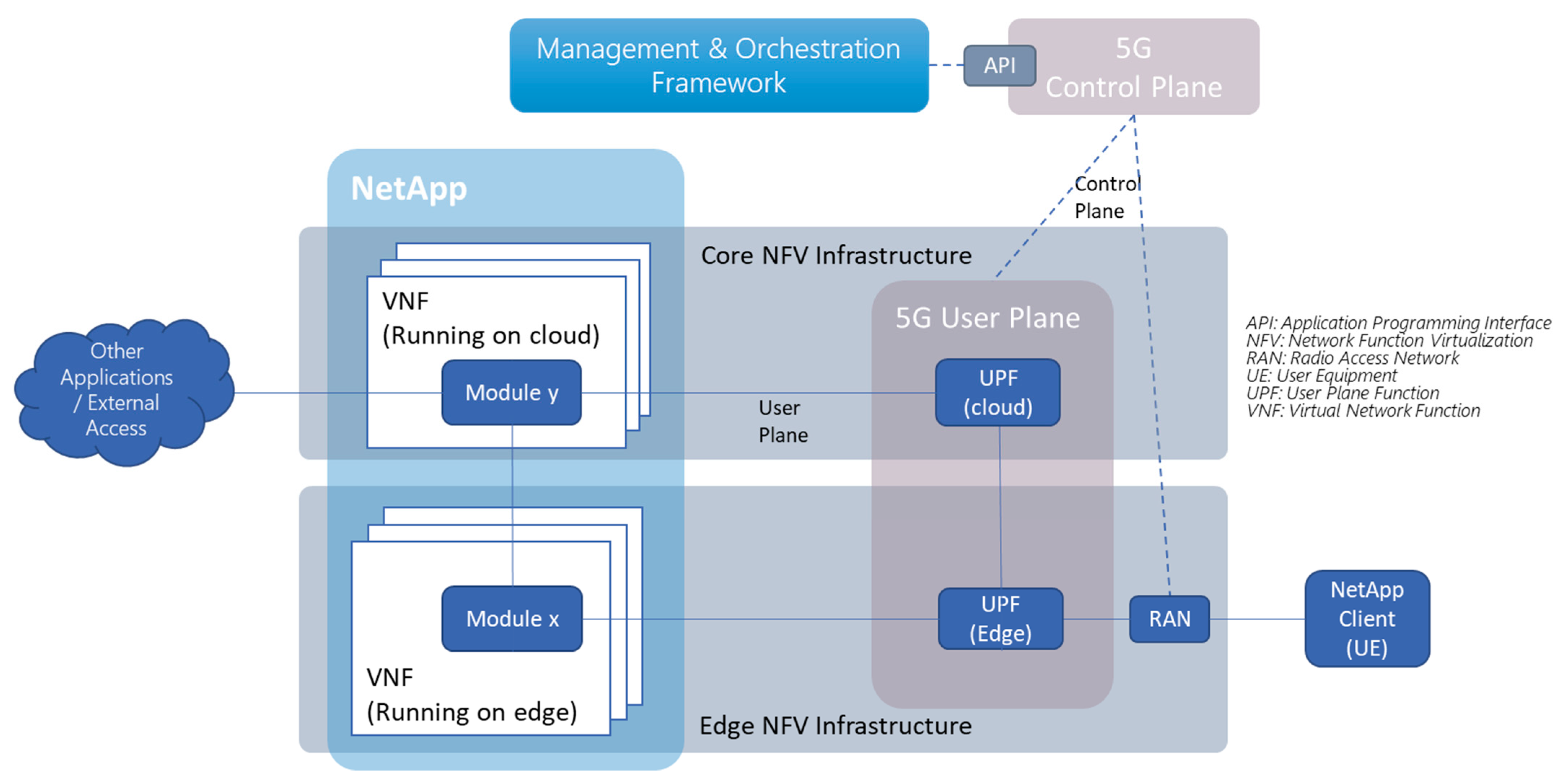
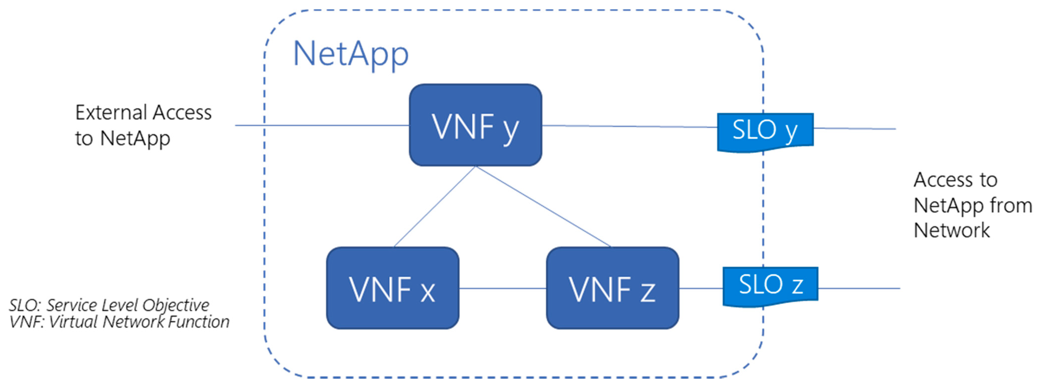
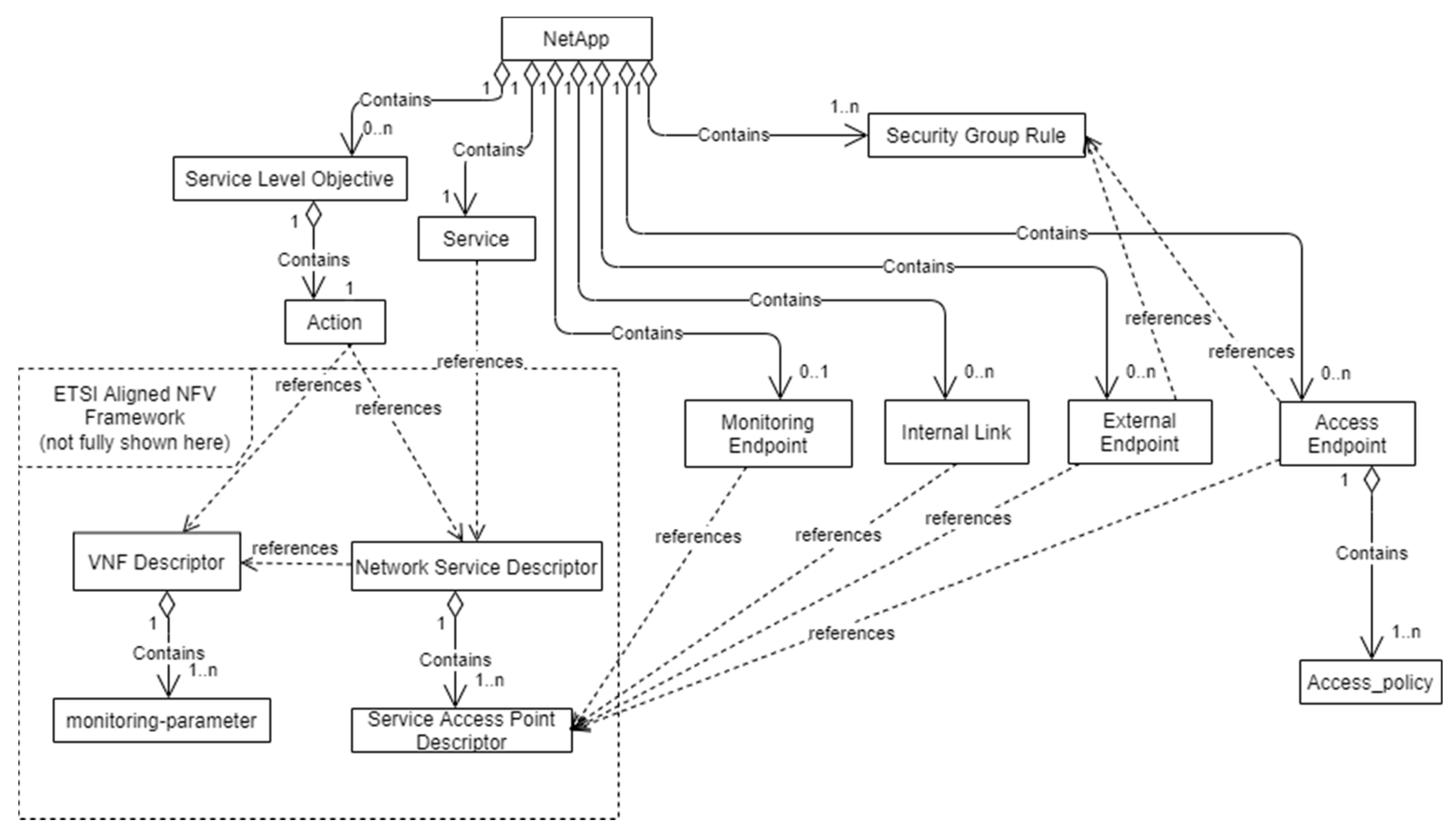
2. Smart5Grid NetApp Concept

One of the Smart5Grid’s main aims is to provide a friendly environment that, abstracting the complexity of the underlying 5G network, facilitates the development of applications for the smart grid. Here is where the NetApp concept comes into play, conceived as a vertical application, composed of a chain of cloud-native virtual network functions (VNFs), able to leverage 5G and edge infrastructure by formally specifying its deployment and performance requirements in its so-called NetApp descriptor.
The split of the functionality of the NetApp into decoupled VNFs is not a new concept. In fact, the European Telecommunications Standards Institute’s (ETSI) network function virtualization (NFV) framework [27] describes the reference architecture, information models, and tools required to manage this kind of application. However, if advanced networking is needed when developing an end-to-end application to run on a 5G network, this framework requires telecommunications expertise from the developers, which usually exceeds their skillset. The Smart5Grid NetApp concept intends to provide a solution to this problem by abstracting the complexities of network configuration from the developers. The Smart5Grid NetApp contains the necessary components to offer the vertical service. It is a standalone application, but it may be also integrated with other external or legacy applications, as shown in Figure 1.
The NetApp components can be deployed as container-based VNFs. By splitting these components whenever possible in the implementation phase, the NetApp brings the opportunity to take advantage of the cloud/edge infrastructure when deployed. Figure 2 shows an example of a NetApp comprised of two components. If there is a VNF that requires low latency, this could be placed at the edge of the computing infrastructure; the other, with less stringent requirements, in a cloud datacenter where resources are less constrained.
Each NetApp is formally defined in a NetApp descriptor, which includes the necessary information regarding the vertical service that comprises it, its topology, as well as the performance requirements of each component so that the infrastructure over which it is instantiated can perform its intended functions, such as multiple-access edge computing (MEC) offloading, VNF scaling, or traffic policy enforcement via its management and orchestration (M&O) system. This information allows the M&O system to create end-to-end slices that fulfill these requirements, allowing developers to design applications with strict performance demands without having the expertise to implement the networks that support them. These concepts will be further explained in Section 3 and Section 4.
With the aim to leverage, as much as possible, the existing state of the art and standards, Smart5Grid proposes to adopt ETSI-aligned descriptors and incorporate them into Smart5Grid NetApps in such a way that existing VNFs can be reused. This, however, may be difficult to bring into reality, as multiple implementations in the orchestration layer are available in the different UC implementations within the project; even ETSI initiatives, such as open-source management and orchestration (OSM), include proprietary definitions of certain aspects, especially in the case of containerized workloads, which are still under specification. For this reason, we propose to use a hybrid solution where a placeholder for ETSI standard descriptors exists, while allowing existing specific implementations to work in such deployments. Figure 3 graphically illustrates the first version of the Smart5Grid information model (IM) in relation to the existing ETSI NFV one.

3. Smart5Grid Platform

Smart5Grid proposes to ease the barriers for new entrants to the energy market (third-party developers and SMEs included) by defining an open 5G platform that, following development and operations (DevOps) practices, will allow the verification and validation of applications and VNFs. This validation will take place in quasi-production environments, not just locally, in advance of their deployment in real operational conditions, thus increasing their trust in the behavior of said applications.

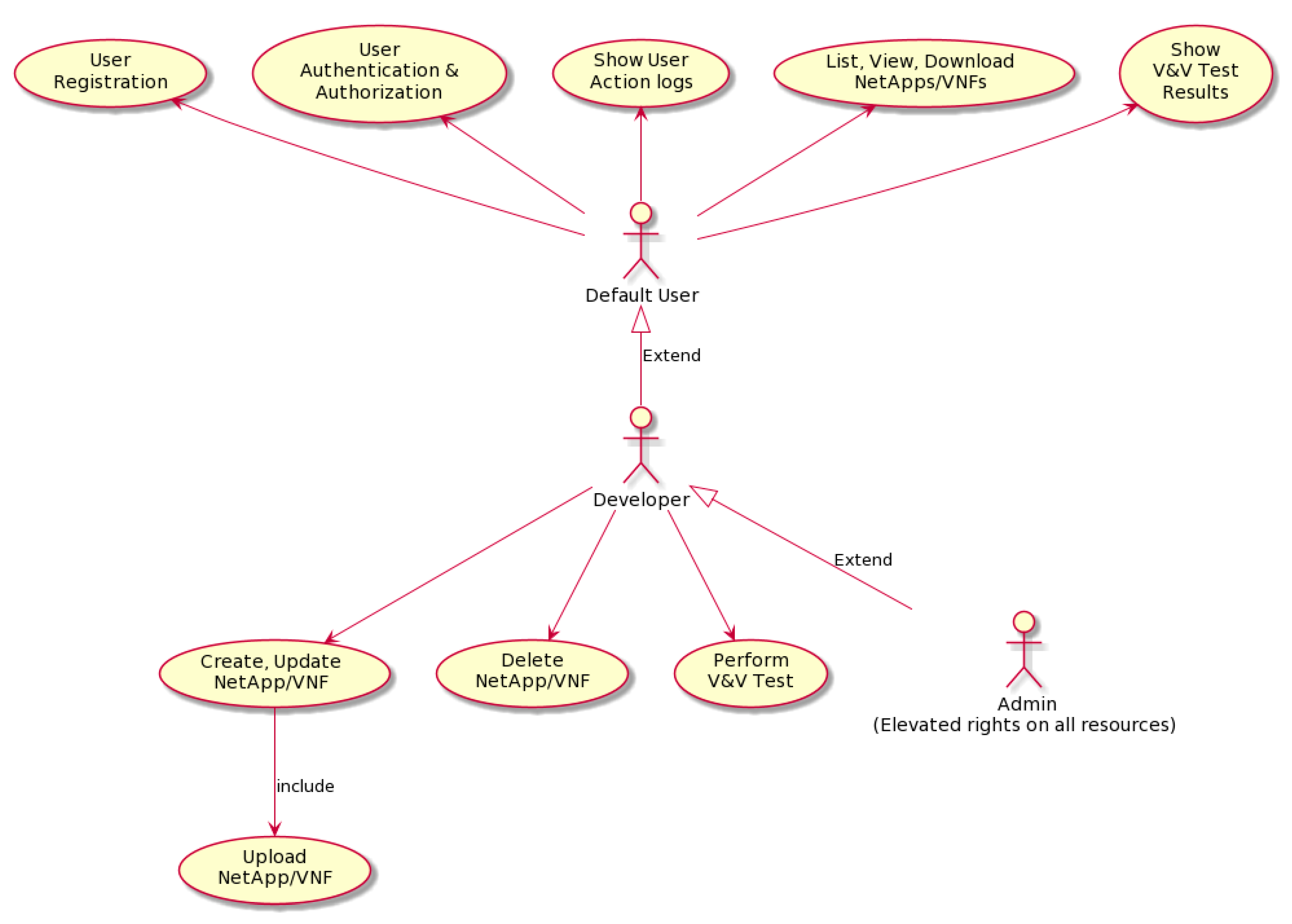
3.1. Main Functionality and Actors

The goal of the Smart5Grid platform is to provide a common platform for NetApp developers and consumers (i.e., energy vertical stakeholders). To achieve this, Smart5Grid proposes a platform containing a repository, the open service repository (OSR) of NetApps that has been thoroughly tested in advance through a verification and validation (V&V) framework. This will enable the creation of a NetApp ecosystem that will allow for sharing NetApps, fostering their visibility but also encouraging collaboration and, therefore, innovation. The main functionalities of the Smart5Grid platform are depicted in Figure 4.

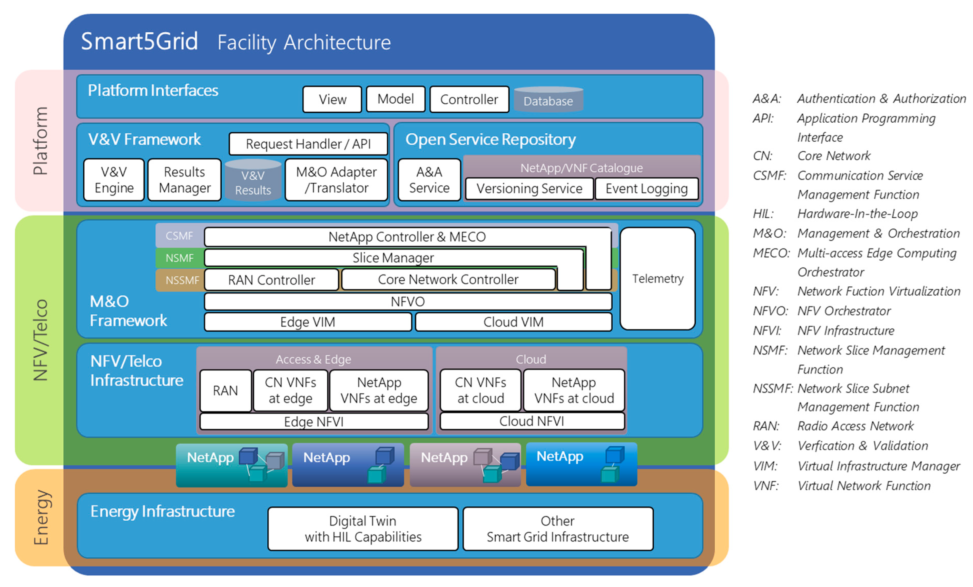
3.2. Reference Architecture

The Smart5Grid architecture, encompassing the platform and the infrastructure over which NetApps are deployed, is depicted in Figure 5. It is logically divided into three layers corresponding to different groups of functionalities. The first layer is the uppermost part of the architecture and contains the OSR and V&V framework, together with the platform interfaces from which users can access it. Next, we find a layer containing the virtualization and telecommunications infrastructure with its associated management and orchestration functions. Lastly, the energy infrastructure contains the grid components that connect to the NetApps services.

3.2.1. Platform Layer

The platform layer is the uppermost part of the architecture, meaning that it is the point of entry for users to the Smart5Grid facility, including NetApp developers as well as NetApp consumers. This point of entry is provided by the user interface (UI) which, in essence, consists of a web application that manages the authorization and authentication of users and provides access to the services offered by the exposed application programming interfaces (APIs) of the other two components of this layer, namely, the OSR and the V&V framework.

OSR

The OSR is the module responsible for the storage and management of NetApps and VNFs. It also preserves logs of the actions performed on the stored NetApps. It consists of a collection of components interacting with each other to provide a unified service to the users, offering access to existing NetApps as well as a complete toolset for the implementation of modern DevOps practices to users developing NetApps. The OSR’s main components include the following:
The authentication and authorization service handles user access to the OSR resources in a role-based access control method. The external user roles that are supported can be divided into two categories, namely the NetApps developers and the NetApps consumers. The developers of NetApps and VNFs can take advantage of the OSR’s DevOps and collaboration functionality to develop and publish their applications, achieving visibility from consumers. In addition, the NetApps consumers can find applications that meet their functional and performance requirements.
The NetApp/VNF catalog handles NetApp and VNF development, storage, and management. It can be divided into two subcomponents—code versioning service and event logging component. The code versioning service has the role of handling the NetApp/VNF code, keeping track of different versions, and providing packages of the NetApp underlying software components. It stores the NetApp/VNF descriptor text files and source code. Developers can use the code versioning service to collaborate on the development of NetApps and publish images to the included image registry. The event logging component keeps track of actions performed on the NetApp/VNF code and packages. Agents collect and push the data to the logging server. Apart from storing the log data, it allows for querying the desired data logs, applying time or object properties filters.

V&V Framework

The V&V framework is split into two sub-modules, the verification and the validation engines. The verification engine assesses the syntax, integrity, and topology of the Net Apps and/or VNFs. The validation engine addresses the information model translation (IMT) module, the onboarding and instantiation in a particular M&O framework, and the key performance indicator (KPI) retrieval and validation. The IMT module was designed in a plugin-based approach to suit future needs of adding the support of more information models and, thus, assuring the growing compatibility of more M&O frameworks.
The verification component of the V&V framework addresses the composition of the Smart5Grid NetApp descriptors. It provides verification on the following elements.
Syntax verification: The NetApp descriptor and corresponding virtual network function descriptors (VNFDs) are syntactically validated against the scheme templates specified by the data model of Smart5Grid.
Integrity verification: The validation of integrity verifies the overall structure of descriptors through the inspection of references and identifiers both within and outside the individual descriptors. As NetApp and VNFDs have different information scopes, the validation goals of this type of activity either in the context of a VNF or NetApp validation are provided as follows:
NetApp integrity: NetApp descriptors typically contain references to multiple VNFs, which are identified by the VNFD. The integrity validation ensures that the references are valid by checking the existence of the targeted VNFs. Integrity validation also verifies the connection points (CPs) of the NetApp. This comprises the virtual interfaces of the NetApp itself and the interfaces linked to the referenced VNFs.
VNF integrity: The integrity validation of a VNF follows a similar procedure of a NetApp integrity validation, with the difference of virtual digital units (VDUs) being defined inside the VNFD itself.
Topology verification: This provides a set of mechanisms to validate the network connectivity graph to aid the development of connectivity logic. Typically, a NetApp contains several inter-connected VNFs, and each VNF may also contain several inter-connected VDUs. The connection topology between VNFs and VDUs (within VNFs) must be analyzed to ensure a correct connectivity topology.
The validation process comprises the deployment and instantiation of the NetApp to be validated by the M&O framework. In Smart5Grid, the V&V platform is expected to have the associated M&O framework to perform the NetApp validation tests, which can be of multiple types as well.
NetApp onboarding: Once the translation process is finished, the next logical step is to onboard the NetApp in the corresponding M&O framework.
NetApp instantiation: At this step, the validation engine will request the instantiation of the NetApp.
Retrieve KPIs: To properly validate the NetApp, the validation engine will ensure that certain specified KPIs are met. Hence, the M&O framework will have a mechanism to measure and provide such metrics.
Validation results analysis: This process verifies if the retrieved KPIs are within the thresholds specified by the developer. It is this process that determines if a NetApp is successfully validated.

3.2.2. NFV/Telco Layer

This layer description specifies the required computing and networking systems that enable the deployment of NetApps. It is divided into two parts that are very tightly related—the M&O framework and the NFV/telco infrastructure.

M&O Framework

The M&O framework is responsible for managing the end-to-end lifecycle of a NetApp deployment. It also provides services to cover all aspects of the complete lifecycle, including onboarding, instantiation, monitoring, scaling, and termination. It is composed of the following components:
The NetApp controller and MEC orchestrator (MECO) manage the NetApps and MEC servers’ lifecycles. This includes NetApp-specific functions like NetApp deployment, migration, termination, set, and forward the required traffic routing rules, but also functions like node (re-)provisioning and configuration. Since this is the component that decides where a NetApp should be deployed, it is usual that the MECO has a broader view than just the edge, and it usually can manage resources ranging from far and near the edge to public and private datacenters.
The slice manager (SM) is one of the key elements that guarantees the management and orchestration of the infrastructure resources, as well as the NetApp service deployment, in an agile way. The SM performs the logical partition in each resource offered by the infrastructure owner (5G radio access and core networks, compute, and transport). These logical partitions, simply named a collection of chunks, represent a network slice instance (NSI), which considers the service requirements specified by the customer. In detail, this component allows for the following functionalities:
(1)
The dynamic provisioning of end-to-end network slices, both at the infrastructure level (infrastructure chunks) as well as at the network level (networks chunks), bearing in mind the performance requirements per slice, such as QoS policies.
(2)
The clients and third parties handle the network slices’ lifecycle management (LCM) in an agile manner in terms of commissioning, deployment, fault, and configuration procedures performed over the chunking resources and the network slices (NS).
(3)
The interaction with the virtual infrastructure manager (VIM) technologies for the management of edge/cloud infrastructures, such as OpenStack, provide better support of multi-tenancy and multi-tier services. In addition, it interacts with ETSI NFV MANO frameworks, such as the open-source NVF management and orchestration (OSM), to coordinate the network services’ LCM procedures in a multi-tier model.
(4)
Seamless and dynamic network service provisioning at the network level by establishing the service chain communication among several network functions, which together describe a NetApp. These NetApps can be distributed along with the multiple infrastructure domains.
(5)
A flexible interaction with open radio access network (O-RAN) [28] aligned access networks to enable a transparent and dynamic resource orchestration of the multiple wireless devices such as small cells, Wi-Fi networks, and 5 New Radio (NR).
The 5G core network (CN) controller is responsible for the management and orchestration of the resources of the CN. It tightly collaborates with the SM, and, in certain deployments, it can be de facto realized as a submodule of the SM itself. It implements some functional capabilities that 3GPP has assigned to the network slice subnet management function (NSSMF) and the network function management function (NFMF) [29,30].
The management and configuration of radio devices of the 5G network are handled by a dedicated management module called the radio access network (RAN) controller. This module, which, depending on its implementation, may be a standalone component or integrated with the SM, exposes the available radio infrastructure to the upper layers of the architecture via its northbound API and enables its configuration and management. The RAN devices of the network are managed over the southbound API of the RAN controller using dedicated protocols.
In Smart5Grid, to manage VNFs and NetApps, it is necessary to focus on two components of the NFV framework. The first component, the NFV orchestrator (NFVO), being the main component of this framework, is in charge of the orchestration of the computing, storage, and network resources that are provided by the second component of this framework, the virtualization infrastructure manager (VIM).
The network/IT infrastructure monitoring is handled by means of the telemetry component, which is the main ingredient able to inform any optimization engine or planning tool on how to place VNFs and NetApps closer to the device or migrate to a more powerful cloud environment if needed. Often, this choice or the potential system configurations are unknown to application developers ahead of time. What may be the right choice for a low-end device (such as a smart meter) with good connectivity may be the wrong choice for a high-end mobile device (such as a drone). Thus, the Smart5Grid platform will collect and manage the different data arriving from the processing and networking infrastructures in a smart way.

NFV/Telco Infrastructure

The infrastructure required is primarily of two kinds—computing and networking. The computing infrastructure is utilized by the M&O framework to deploy the software components in the form of containers that constitute a NetApp. This computing infrastructure can be centrally located or placed at the edge to benefit from reduced latency communications. The networking infrastructure is formed of networking nodes in both access and core domains such as 5G gNodeBs (the 5G base stations) and CN functions, which are orchestrated to meet the traffic demands of a NetApp. With regard to the open-source cloud infrastructure software, different solutions can be considered as possible implementation choices, such as Openstack [31], Cloudstack [32], or OpenNebula [33], while with the recent advances within containerization, cloud-native VNFs may now run in a container rather than a virtual machine, with their lifecycle orchestrated by a container orchestration engine, such as Kubernetes [34]. The adoption of a specific solution depends on the requirements of the specific UC.

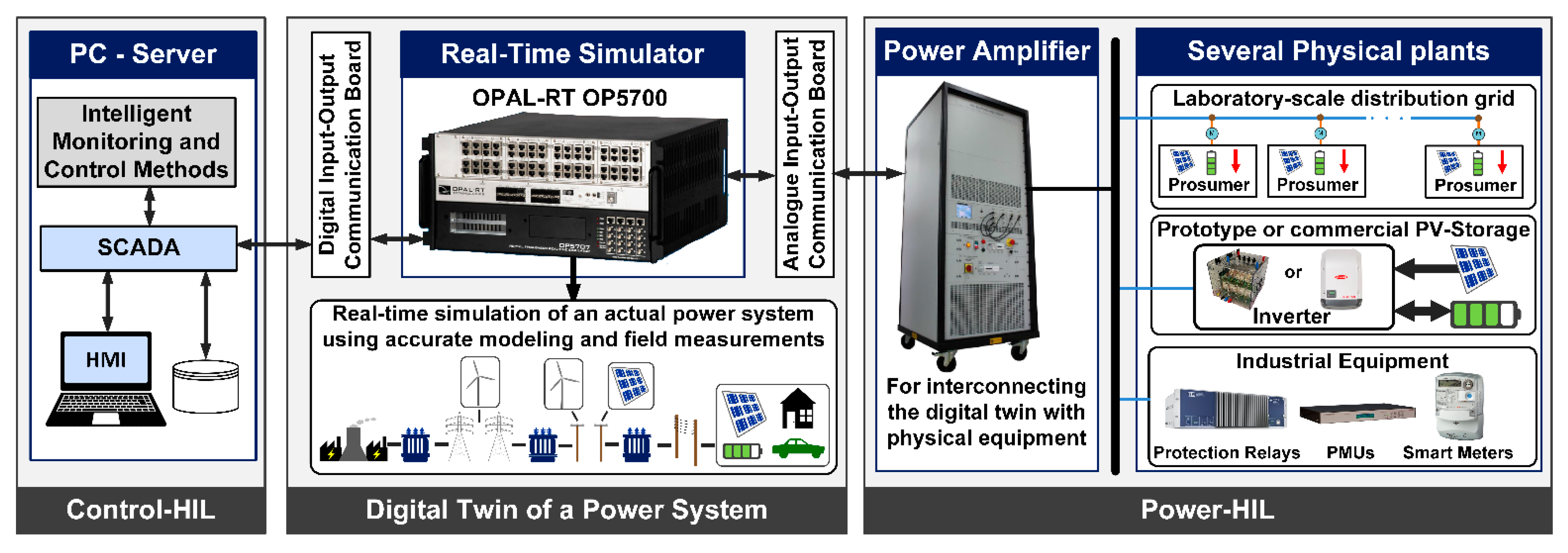
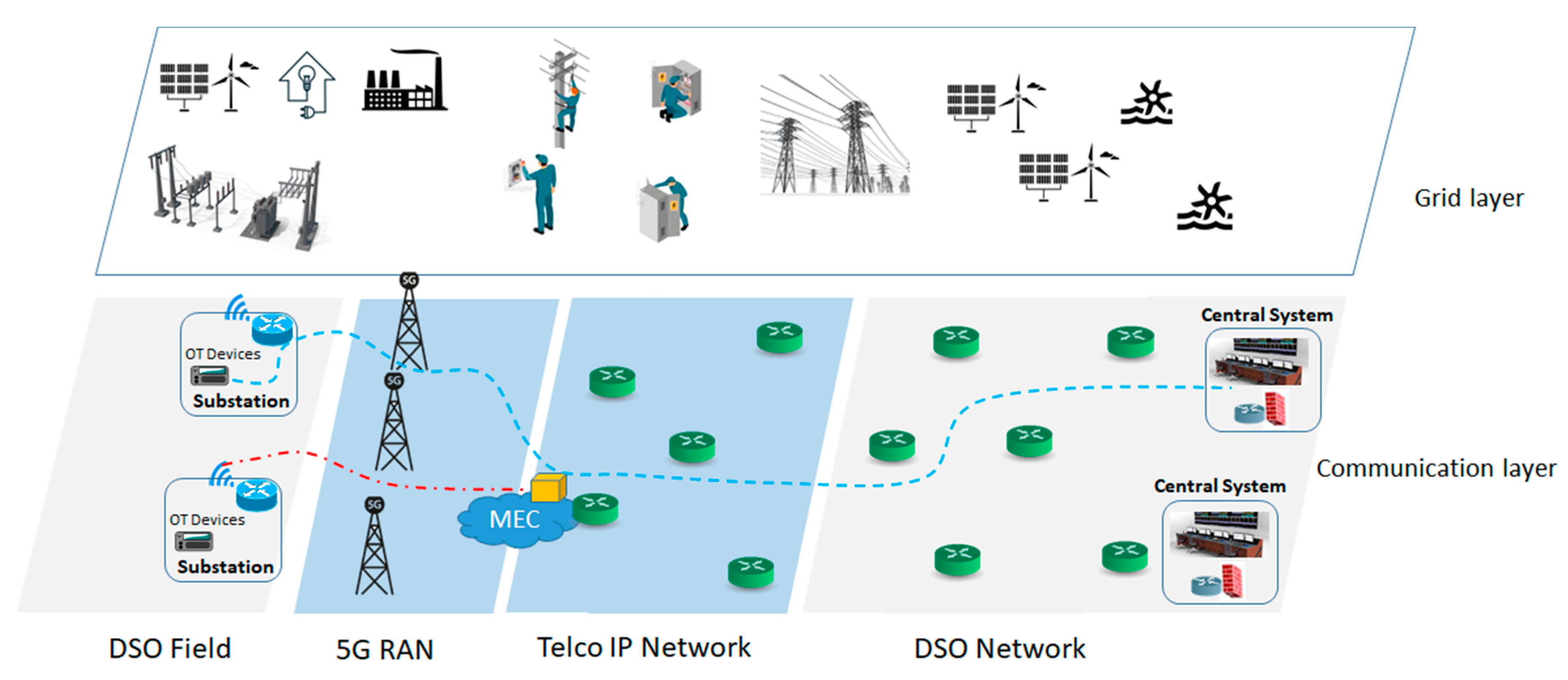
3.2.3. Smart Energy Grid Layer

The smart energy grid layer is the environment where the data is both generated (e.g., by sensors, advanced measurement, and instrumentation units such as phasor measurement units, amongst others) and received (e.g., by intelligent controllers of distributed energy resources, automated remote terminal units, applications supporting the reliable and safe operation of the grid, and so on).
Power systems are highly critical infrastructures [35]. Therefore, before deploying any new equipment or sub-system solutions that may affect the actual operation of the grid, it is mandatory that these solutions are thoroughly tested and validated in a controlled power-grid related operation environment, such as a digital twin, real-time hardware-in-the-loop (RT-HIL) testbed infrastructure. As such, in the general Smart5Grid architecture, the smart energy layer is virtually represented by a flexible, pre-piloting smart grid layer.
A general architecture of the pre-piloting testing facility, or the virtual smart grid layer, is depicted in Figure 6. It is comprised of three main architectural blocks, and only part or all of them may be required depending on the specific operation scenarios to be tested and validated. The role of each of these components, and how the Smart5Grid platform will be integrated into this setup is briefly described below.
Digital twin of a power system: The implementation of a digital twin of a power system is crucial for creating realistic conditions to test and validate the energy-specific NetApps, which in turn aim to provide additional services for the grid and enable the power systems’ evolution. To accomplish this, a dedicated real-time simulator (RTS) (e.g., OPAL-RT OP5700 [36]) can be used. Field measurements (collected from actual power plants either online or through measurement campaigns) are employed in these simulations to replicate the operation of selected power systems as digital twins. As a result, a digital twin of an actual power system allows the execution of studies and investigations for evolving the operation of a smart grid without risking the integrity of the infrastructure.
Control-hardware-in-the-loop (control-HIL): This is a framework where the Smart5Grid platform, along with the developed power grid controllers, are included in the loop with the digital twin of the power system implemented in the RTS. To consider the complexity of the power system in real time, either a small-scale prototype plant or the digital twin of the actual power plant can be used. Thus, the controller can receive measurements and send control set-points to the power grid under test (digital twin), emulating realistic conditions for the demonstration. In actual power grids and control-HIL frameworks, the real-time responsiveness of the controller is crucial for the stability of the grid along with any communication or processing delays.
Power-hardware-in-the-loop (power-HIL): This investigates the interaction between the power grid under test (digital twin) and a physical power equipment in the loop. This allows the testing of how a prototype or a commercial equipment will operate when it is connected to a specific location within an actual power system. Therefore, the dynamics of the power systems are replicated in a realistic way to investigate the operation of physical equipment under a relevant environment. Examples of physical power equipment are PV plants, battery storage systems (BSSs), the electrical installation of a building, wind turbines (WTs), devices used by the power industry (i.e., smart meters, phasor measurement units (PMUs), protection relays, etc.), and micro or nano-grids, amongst others. On the other hand, power-HIL is crucial for validating and demonstrating how new power equipment will properly operate when it is connected to an actual power plant. For the latter case (e.g., the development of prototype power equipment, such as wind power inverters or a new protection system for the power grid), the power-HIL infrastructure can be used for validating the operation of the prototype equipment under extreme scenarios and realistic conditions.
It should be noted that for the investigation of the interaction between the power grid under test (digital twin) and a market-available or prototype plant to be integrated into the smart grid (e.g., aiming for new or more advanced functionalities or services), a power interface is used. In this context, the power equipment is interconnected to a selected bus within the digital twin through a power amplifier. The power amplifier replicates, in every solution step of the digital twin (e.g., every 50 μs), the voltage conditions of the selected bus, and this voltage supplies the power equipment. The operation of the power equipment (power exchange with the amplifier) is considered by the digital twin to accurately emulate the interaction between the two.
Finally, the integration of the Smart5Grid platform and telco layers in this smart grid testing environment can be done at the macroscopic level using a hardware network emulator (NE) in the loop. This is, in essence, a software-defined test network that mimics a set of significant characteristics of real-world networks, including 5G technology (e.g., the telco layer in the Smart5Grid architecture). The NE allows for creating controllable and repeatable network conditions, such as latency and jitter, re-ordered or duplicated data packets, lost/corrupted data or queueing and congestion conditions, amongst others. Based on the NetApp KPIs retrieved from the V&V process, the NE will be configured to replicate similar communication characteristics expected to occur in real-world telecommunication infrastructures, aiming to investigate the communication impact on the power-HIL loop.

4. Smart5Grid NetApp Use Cases

This section exemplifies the application of the NetApp concept in the context of the Smart5Grid demonstrators, also known as UCs.

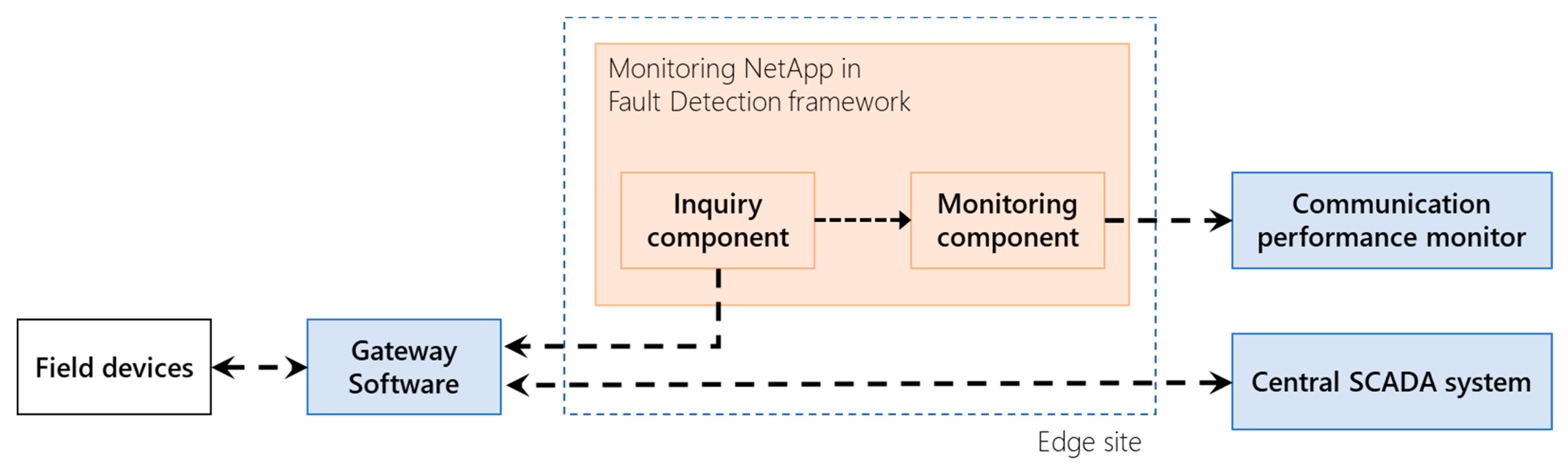
4.1. UC1—Automatic Power Distribution Grid Fault Detection

4.1.1. Description

Real-time self-healing is a function in electricity distribution networks that consists of the automatic search and isolation of a portion of the distribution network affected by a grid fault, aiming to lower the impact on the involved energy users. This function requires very low latency and reliable communication in any environmental condition to allow self-reconfiguration of the network without an electricity supply interruption to end users. One of the critical aspects when investigating the cause of the malfunction of such an automation system is to be able to continuously monitor how the communication infrastructure works, for example, quickly identifying if the problem originated in the power circuit breaker, in the actuators, in the sensors, or due to communications errors. Currently, there are two types of communication technologies used for this advanced automation system—4G network technology and optical fiber. While the latter is recognized as a reliable communication technology for this automation system, its implementation is costly and less scalable for remote areas. On the other hand, implementations that use 4G technology are very scalable and cheaper than those with optical fiber, but they could not guarantee very low latency and highly reliable communication, especially in congested network situations. The goal of this UC is to reduce the complexity, time, and cost required in the troubleshooting process of the advanced self-healing power distribution automation system when an abnormal condition occurs. As such, this UC implements a telecommunications network monitoring mechanism, in the form of a NetApp, that continuously, and in real time, oversees the network status of all the remote field devices involved in the advanced self-healing automation system of a selected geographical area.

4.1.2. Requirements

The smart fault selection automation framework requires ultra-reliable low latency communication (URLLC), which means high service availability (over 99.99%), high communication reliability (over 99.99%), and end-to-end latency below 40 ms, on top of high standards of cyber security and end-to-end encryption of data. The aim of this UC is to verify and validate this requirement and to also create a NetApp for the continuous monitoring of the telecommunications infrastructure and its performance.

4.1.3. Specific NetApps

The infrastructure in this UC includes three main software components—the gateway, the NetApp monitoring and fault detection, and the central supervisory control and data acquisition (SCADA) system, as illustrated in Figure 7.
The gateway software is responsible for collecting the network traffic from the deployed sensors, compiling them into a common format, and forwarding this network flow into the NetApp. The inquiry component in the monitoring and NetApp will generate monitoring traffic to collect data on the communication layer quality. The monitoring component will collect and analyze the raw data to make them available to the performance monitor in the distribution system operator’s (DSO’s) control room, supporting troubleshooting for the telecommunications infrastructure.

4.1.4. Site Architecture

The pilot site of UC1 consists of several remote, medium voltage (MV) power substations along two contiguous feeders in which the smart fault selection automation framework will be implemented. The site architecture is presented in Figure 8.
The MV protection devices and remote terminal units (RTUs) forward the collected data to the local gateway. Its purpose is to send them through the DSO telecommunication infrastructure to the central systems in order to ensure the remote control of the electric grid and, in the meantime, also ensure the interaction with other MV protection devices in the field, with the aim of automatically finding and isolating a fault on the grid when it occurs. The MV protection devices use standard communication protocols, such as IEC 61850-MMS/GOOSE [37] and IEC60870-5-104 [38].
The 5G network enables the gateway to send and receive, in a very fast and reliable manner, the information coming from and destined for the local MV protection devices. In addition, this kind of mobile communication network enables innovative edge computing functions provided by the telco operators.
In this demonstration, we will use the computing and data storage resources provided by the local telco to implement a NetApp that collects information concerning the state of the 5G radio access network versus each gateway of all substations involved in this pilot.
The objective is to have a clear view of the communication network layer so as to ensure better electric service levels and to dispatch the DSO technicians to the field only when it is strictly required.

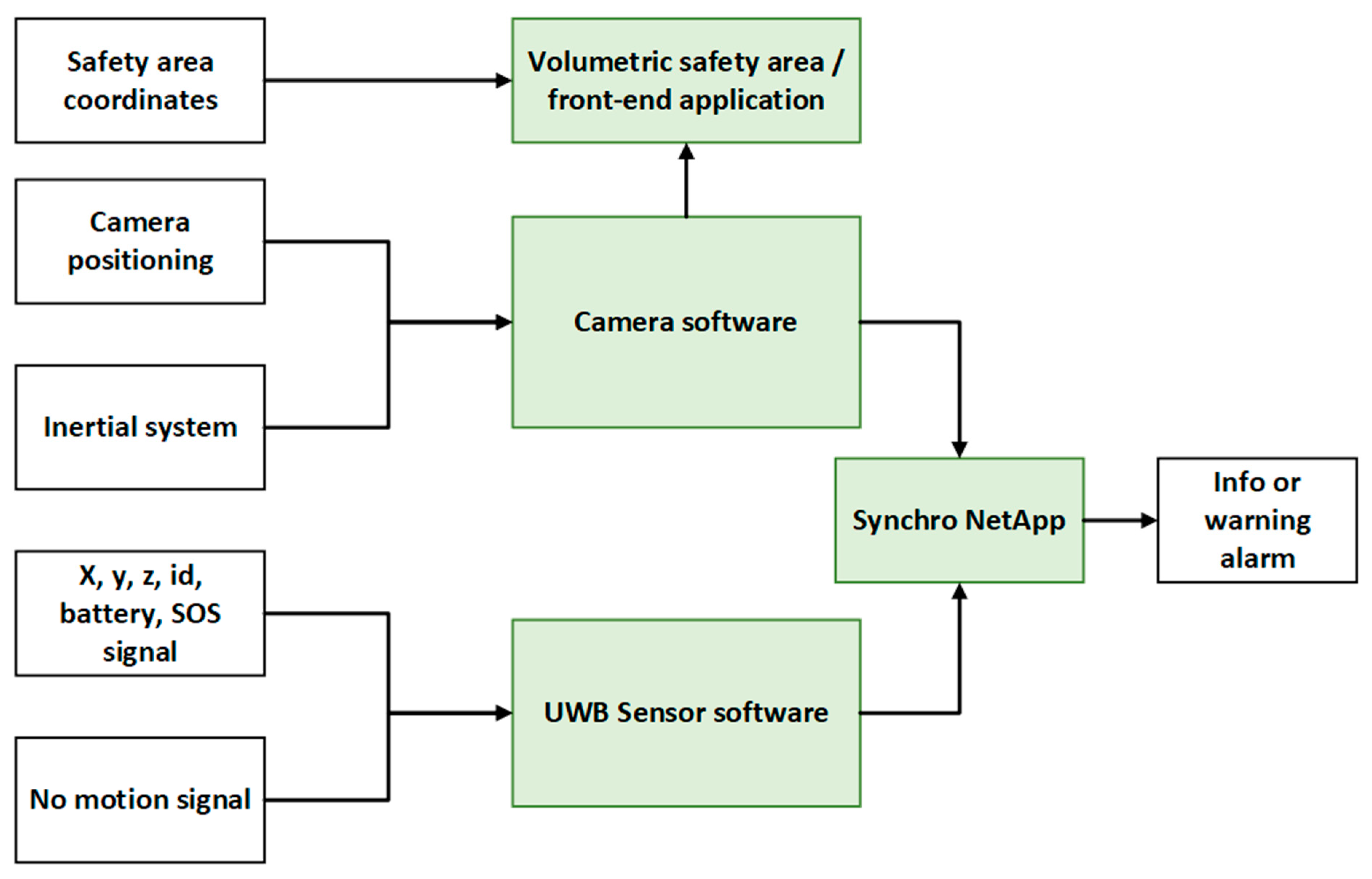
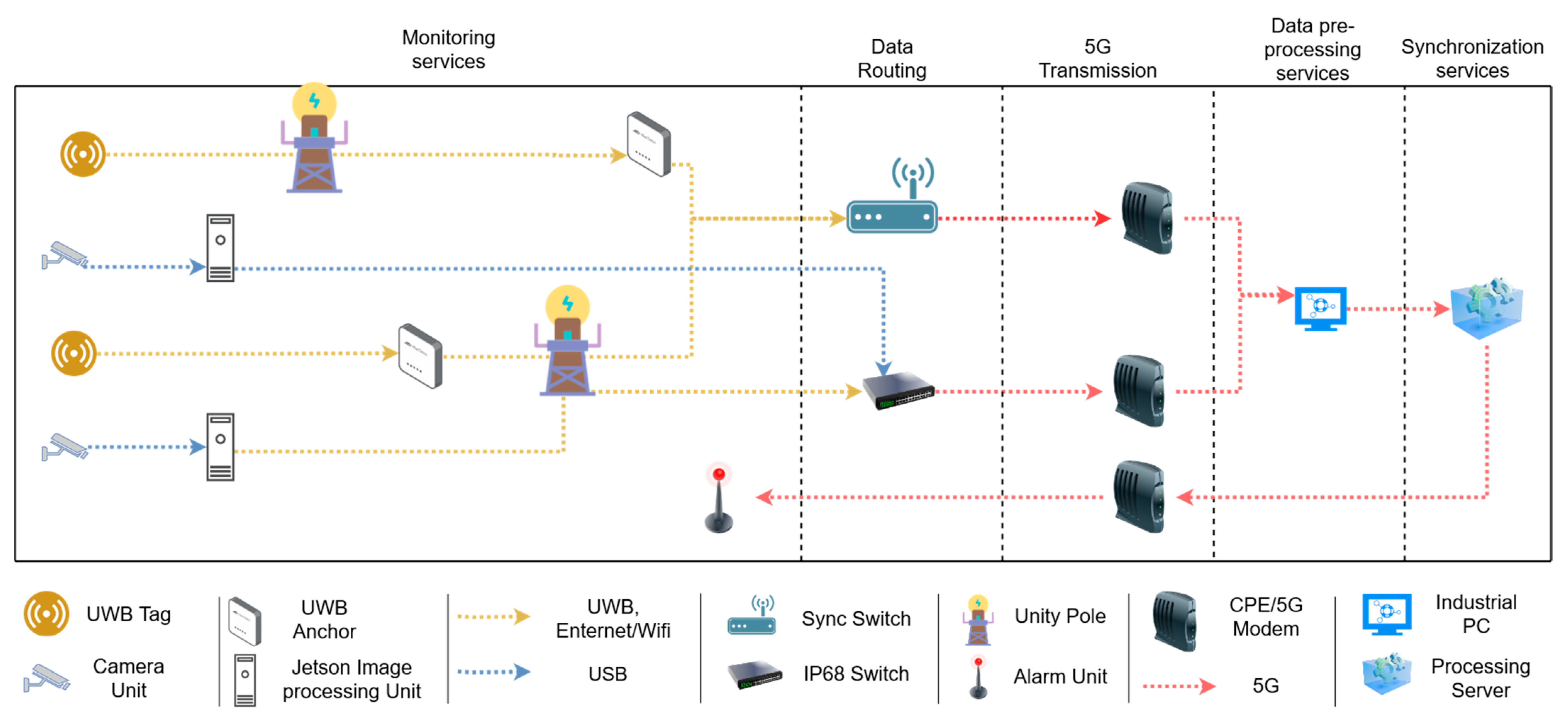
4.2. UC2—Remote Inspection of Automatically Delimited Working Areas at Distribution Power Systems

4.2.1. Description

The physical security of personnel that work in electrical power substations is of major importance for every energy operator, since these substations, with voltage values over 66 kV, pose a very high risk. The safety standards in these substations are the highest, while constant revisions take place, integrating the latest technological advances. In the context of Smart5Grid, the 5G functionalities, through the development of different NetApps, aim to enhance safety measures and provide a safer working environment.
Currently, the maintenance process safety rules in the electrical power substations are very strict and are performed in direct coordination with the power substation’s control room. Specifically, currently, a colored paper tape is placed by field workers to indicate the safe delimited working areas of the substation. Further, field work in the safe areas is always visually supervised by the worker’s team maintenance supervisor.
The current infrastructure uses two different safety systems. The first one is a camera with integrated image recognition software that provides an overview of the workers that are physically located in the substation. The second one is an ultra-wideband (UWB) system that provides basic location information through tags and anchors. The technological leap on the current infrastructure is to merge data from different sources, process them, and implement the communication channels using 5G technology.

4.2.2. Requirements

Due to the type of sensors involved in this UC, two types of slices are required— URLLC for camera sensors and enhanced mobile broadband (eMBB) for the wearable sensors. Specifically, this UC requires, in the case of the URLLC slice, end-to-end latency below 100 ms, location accuracy below 0.5 m, and a data rate below 0.01 Gbps. In the case of the eMBB slice, end-to-end latency below 200 ms, location accuracy below 2 m, and a data rate below 0.15 Gbps are also required.

4.2.3. Specific NetApps

This UC NetApp introduces a mechanism that detects, in real time, the exposure of workers and their tools when they enter a forbidden area while working in a power substation. It includes four software (SW) components that communicate with each other, providing a higher level of safety to the workers compared to the current safety installation. These include the front-end application, the Jetson camera software, the UWB software, and the Synchro NetApp, as can be observed in Figure 9.
The front-end application is responsible for illustrating the volumetric safety area, allowing the safety manager to define the forbidden zones and monitor the actions in real time. The Jetson camera software accompanies the camera unit. It receives the image from the camera, and it integrates a neural network capable of detecting movement. The UWB software collects the information from the deployed sensors. As the workers are moving in space, their actions are captured by the sensors and delivered to the Synchro NetApp.
The Synchro NetApp receives and merges the information from the previous components and evaluates and validates it to trigger the alarm system, if necessary.

4.2.4. Site Architecture

Figure 10 presents the system that will be developed for this UC. The UWB unit (tag and anchor) streams the data to the sync switch, and then the data are transferred via 5G NR into the virtualized function(s) of the NetApp. The camera unit (camera device and image processing unit) delivers the output, passing through an IP68 switch to the NetApp via 5G NR. The synchronization NetApp collects the information from the two devices, evaluates it, and informs the workers on site if they—or their equipment—have entered a forbidden zone, triggering both the vibration mechanism in the UWB tag and the alarm unit (optical and sound alarm).

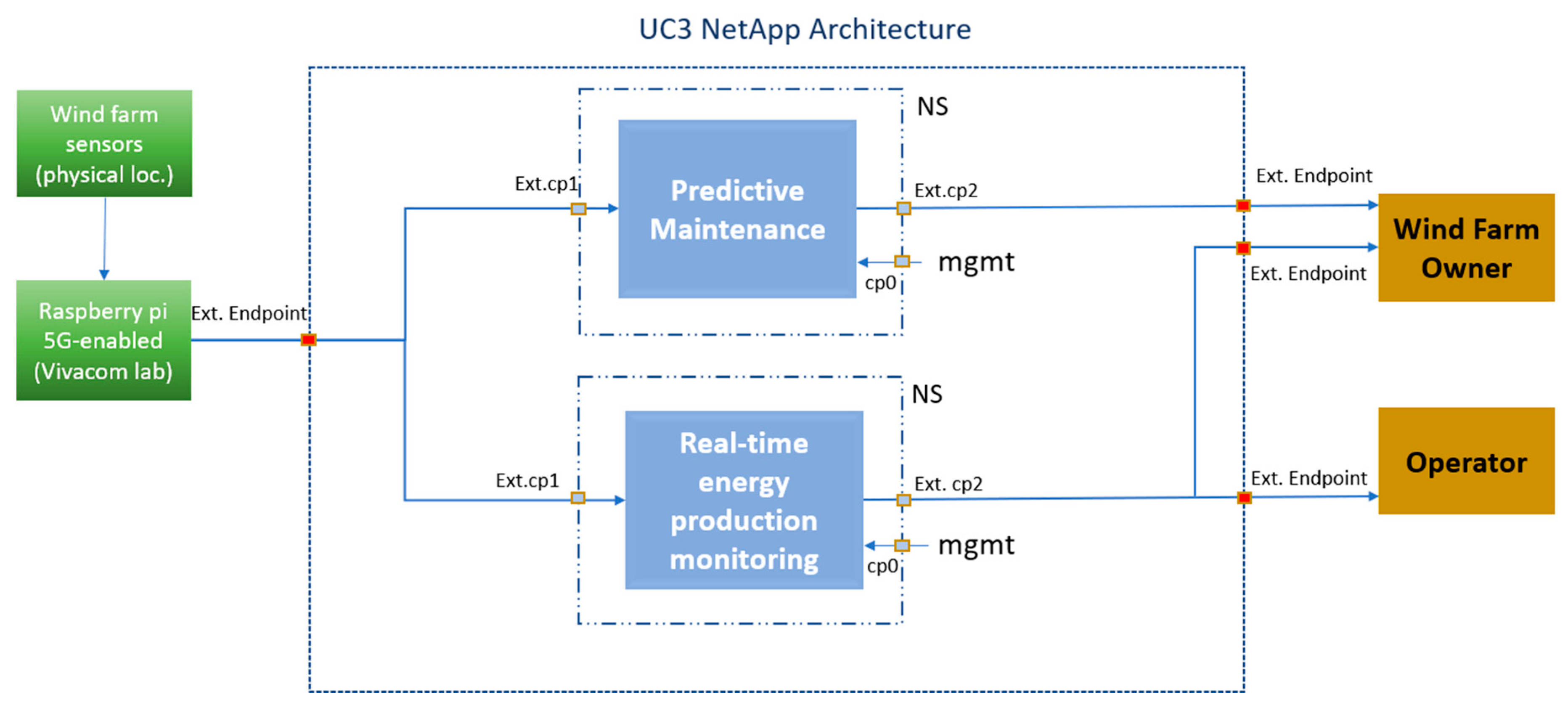
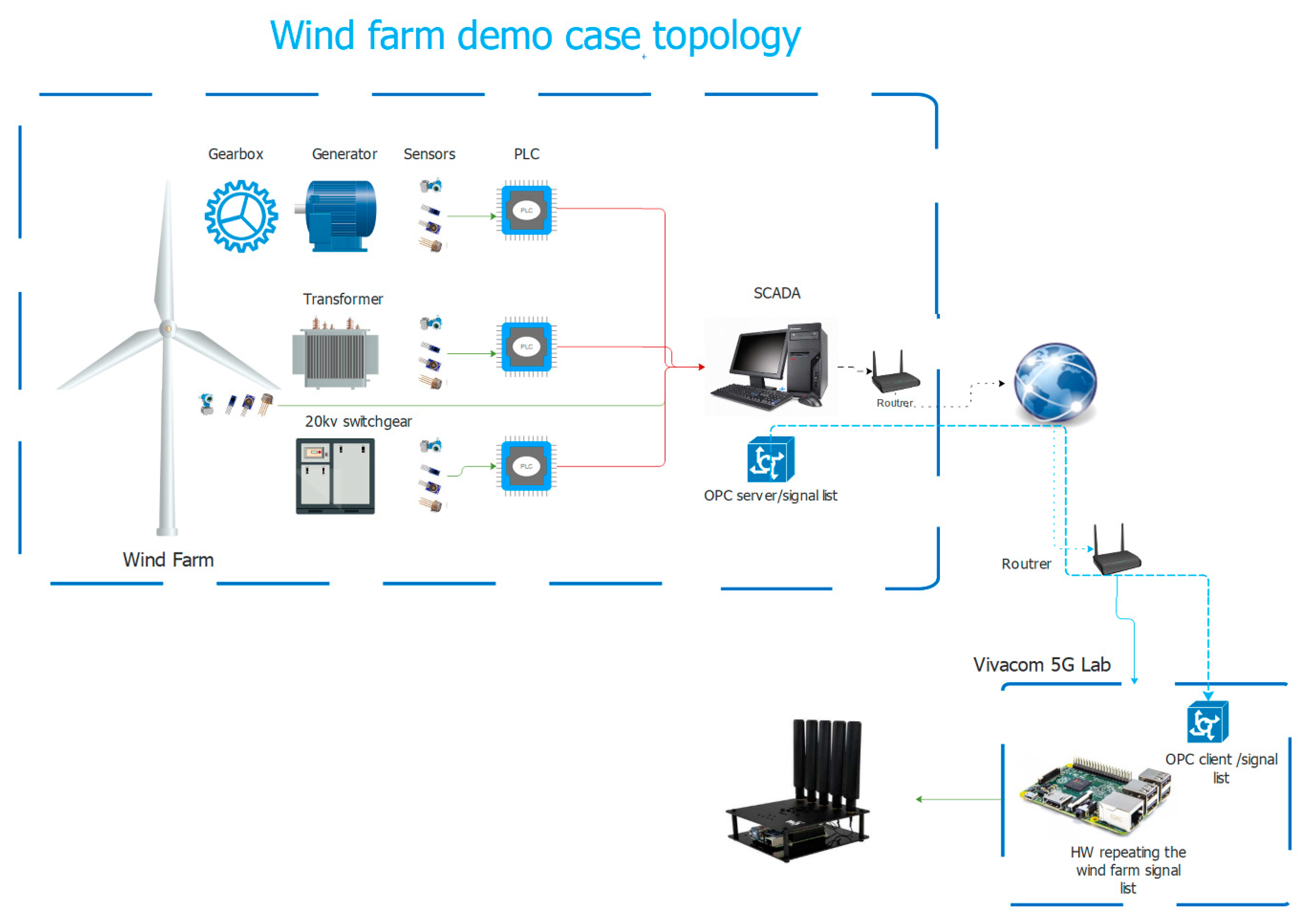
4.3. UC3—Millisecond-Level Precise Distributed Generation Monitoring

4.3.1. Description

The scope of this UC is to monitor, in real time and with millisecond-level precision, multiple DERs, mostly renewables, with the aim of providing reliable flexibility services for real-time balancing electricity markets. In order for an energy entity to be allowed to participate in the real-time market, they need to adhere to strict requirements set by power system operators (TSOs or DSOs, depending on the voltage level where the DERs are connected). While the power output of RES units is uncertain by nature (e.g., it cannot be predicted accurately a few hours ahead of the actual generation time), these power generation units do possess a reasonable level of operation flexibility for participating in real-time balancing market services, such as frequency control. However, for offering such services, they require reliable and accurate real-time monitoring.
Specifically, in the context of this UC, the real-time monitoring of a wind farm located in southeastern Bulgaria is being performed. It is worth mentioning that while this UC targets a wind farm, it could be easily replicated for other types of RES, such as PV farms or micro hydropower plants.
On the one hand, high-granularity precise monitoring of the real-time power production offers wind farm owners the capability of minimizing their cost and, at the same time, being eligible for the provision of ancillary and innovative flexibility services (such as voltage regulation, congestion management, etc.) through flexible plant management. On the other hand, as wind farms are often located in remote areas, fast and reliable communication solutions, such as optical fiber, would have prohibitive costs. In addition, 4G technology could hardly guarantee the millisecond-level transmission of field measurements with high reliability of service and high availability of communication as required by this UC. Fifth generation technology appears to possess the right balance between cost and the QoS needed for such types of energy applications. Furthermore, scalability towards the monitoring and operation of thousands of such geographically distributed RES generation units (e.g., in the case of an aggregator) could become a reality on the assumption of large deployment and adoption of 5G technology in the energy sector.

4.3.2. Requirements

Several strict communication requirements are to be highlighted in line with this UC. They are related to the need for at least two types of services, such as URLLC—needed for the real-time monitoring function of the wind farm—and massive machine type communication (mMTC), in line with the scenario of synchronized real-time monitoring of thousands of DERs to be operated by an energy aggregator. End-to-end latency between 20 ms and 200 ms is expected to address the TSO/DSO requirements for eligibility to participate in the real-time balancing electricity market. However, the communication service also needs to be highly reliable and available.

4.3.3. Specific NetApps

This UC’s NetApp consists of two software components, namely the predictive maintenance enabler service and the real-time energy production monitoring service. Each one of these components is implemented as a different VNF, which are interconnected, interact with the inputs, and provide the necessary outputs to fulfill the functional requirements of this UC, as can be seen in Figure 11.
As it can be observed from Figure 11, the predictive maintenance and the real-time energy production monitoring VNFs have an external connection point (CP), which receives field measurements via a SIM8200EA-M2 5G HAT type module [39]. This module enables the 5G communication with a Raspberry Pi IoT device [40]. It is worth mentioning that many monitoring devices or measurement units for power grids available in the market today, including wind turbine technology, are not 5G-ready. As such, 5G-enabling interfaces might be needed to facilitate the communication between the field sensor devices and the Smart5Grid platform.
The main scope of the NetApp component that performs predictive maintenance is to enhance the awareness of the wind farm owner on the need to make changes in the operation of the wind farm or on the portfolio of the flexibility service it might offer in the real-time balancing market. Specifically, this NetApp component is leveraging the data measured from the sensors that exist in the wind farm, which are then forwarded through an open platform communications (OPC) server, located in the laboratory of one of the project’s partners where the actual processing takes place. The data generation process is repeated in a Raspberry Pi, which possesses a 5G-HAT type module, those supporting 5G connectivity. OPC unified architecture (UA) [41], which is a machine-to-machine (M2M) communication protocol for industrial automation developed by the OPC Foundation [41], will be used as the communication protocol in the context of this use case. Afterwards, this component collects the data and executes an internal process to assess the wind farm operation to conclude whether any predictive maintenance action must be taken. Thus, wind farm owners receiving the input from that component increase their ability to more properly operate the asset.
The second NetApp component implements the wind farm performance monitoring process. Specifically, key performance parameters (such as turbine rotation and vibration) are collected from field sensors. Moreover, environmental parameters (such as wind speed, humidity, and ambient temperature), along with electrical parameters (such as power output, grid frequency, and voltage), are also collected and processed.
The real-time energy production monitoring, the second software component of UC3’s NetApp, provides real-time data monitoring of the wind farm production on a millisecond basis to the owner of the wind turbine and to the system operator. The data collection process follows a similar approach as the previously described software component. Finally, the two software components have a management CP in order to grant access for configuration or debugging purposes.

4.3.4. Site Architecture

The demonstration site for UC3 is presented in Figure 12 and consists of a wind turbine (the power asset to be monitored in real-time) and several electrical and mechanical sensors and measurement units, which directly communicate, via power line communication (PLC), the status of the wind turbine to a local SCADA and to an OPC server/client pair, as can be observed in Figure 12. The local SCADA is usually a closed, proprietary unit of the wind turbine vendor, with closed, internal applications for monitoring and control of the wind turbine. In this respect, the owner of the wind turbine can make use of the widely accepted industrial communication standards, such as the OPC server/client pair, to enable the exchange of data between legacy sensors of the wind turbine and other sensors or measuring units (e.g., multi-vendor IoT devices) needed for advanced monitoring and control actions in line with the real-time flexibility services. A digital version of the wind turbine will then be accurately modeled by a hardware–software unit that is 5G-enabled (the Raspberry Pi block presented in the UC3 NetApp architecture). The exchange of information between the wind turbine digital unit (Raspberry Pi) and the UC3 NetApp will be facilitated by the Smart5Grid platform and the 5G telco infrastructure available at the premises of the 5G laboratory of one of the partners involved in this demonstrator.

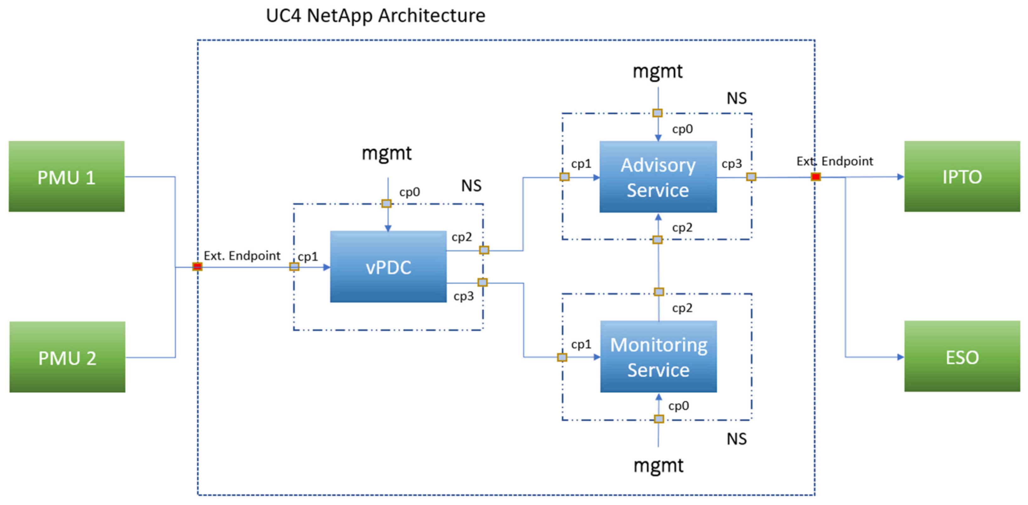
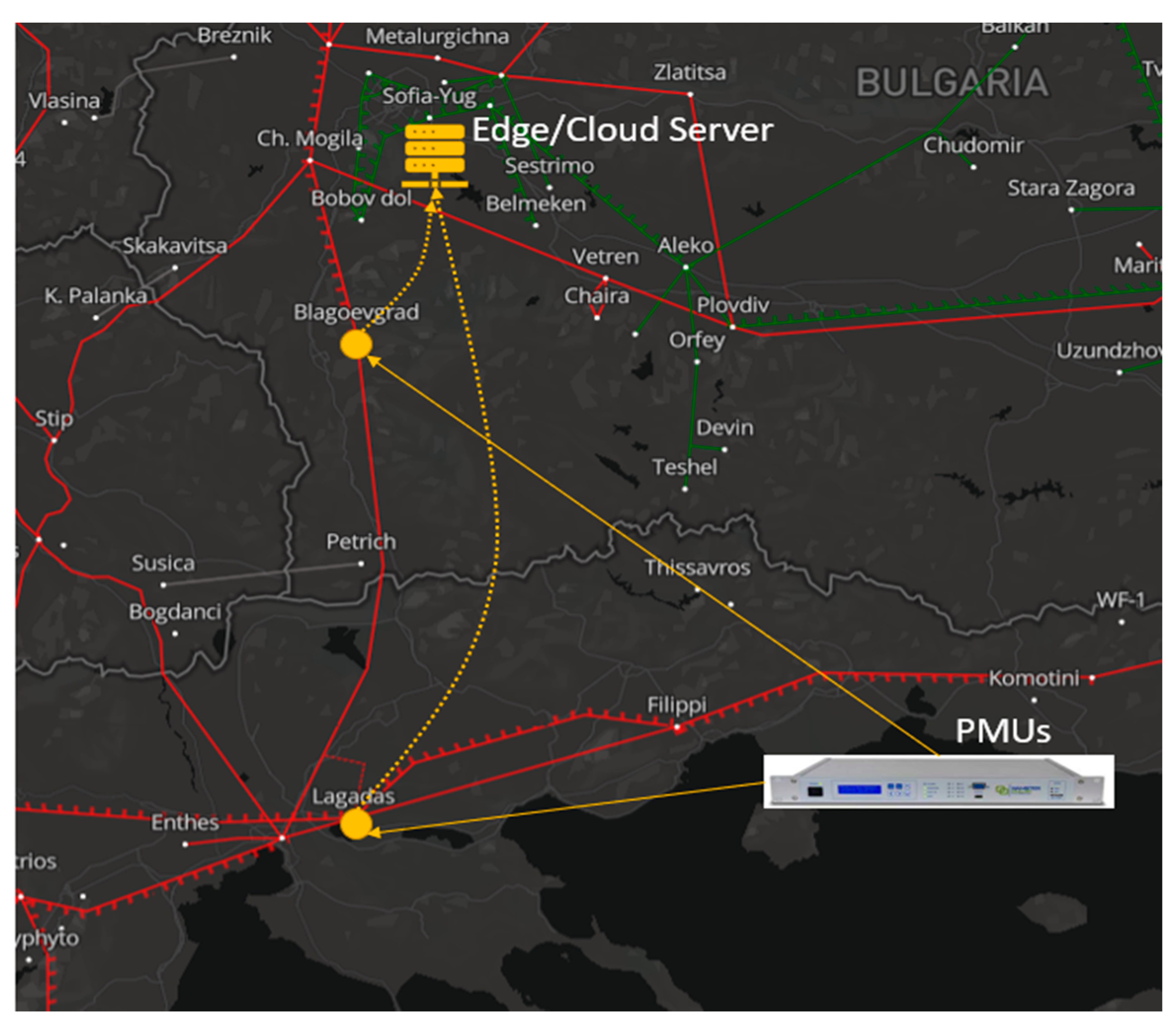
4.4. UC4—Real-Time Wide Area Monitoring

4.4.1. Description

The scope of UC4 is the real-time monitoring of a geographically wide area where cross-border power exchanges (or between two TSOs) take place. UC4 addresses the energy reliability and security domain of the broad energy vertical. Specifically, in the context of this UC, the interconnection flow between Greece and Bulgaria is monitored, leveraging the advantages provided by the 5G telecommunication infrastructure. This function can be executed from the newly established regional security center (RSC) in Thessaloniki, Greece. The role of the RSC is to promote regional cooperation and to support the strengthening of the neighboring power systems and market operations in the region. To achieve the enhancement of the interconnected power system operation, live monitoring of the power flows between the countries under its area of interest is of vital importance. Hence, this UC can be considered the development of an additional element that increases the live monitoring capability of the RSC. PMUs located at the HV network of northern Greece and Bulgaria, monitoring the interconnection area with Bulgaria, can be used as an input in the monitoring process of the RSC. By incorporating time-stamped synchronized PMU measurements with high data granularity (50 to 60 times per second), including positive, negative, and zero sequence phasors of voltage and currents can be achieved.
A virtual phasor data concentrator (vPDC) will be developed for the data-gathering process. The utilization of 5G in UC4 contributes to the connectivity between the PMUs and the vPDC, offering the low latency and high reliability needed due to the criticality of the UC. In addition, 5G provides a low-cost, last-mile connection to the PMUs in remote areas where optical fiber has a high installation cost. Hence, the NetApp envisioned to be developed in the context of this UC, in order to fulfill the above-mentioned objectives, will cover three types of services—vPDC service, WAM service, and advisory service to the involved TSOs.

4.4.2. Requirements

Phasor measurement technology is increasingly deployed in the transmission side of the power grid, aiming to improve the monitoring function of the grid, especially the state estimators. This technology is very useful, especially when inverter-based power generation is present in significant percentages (e.g., above 30–40%), leading to faster dynamics of the grid. While these advanced measurement units are able to record power system states with high granularity, the communication link needs to also satisfy requirements such as high availability of service and high communication reliability in order for this information to be available to the TSO. Specifically, this UC requires a dedicated slice for URLLC, able to transmit measurements with end-to-end latency between 20 ms and 200 ms. The communication delay between the PMU and the vPDC must be below 40 ms, which is the waiting time of the vPDC. When this time is exceeded, all data transmitted by the PMU and arriving at the vPDC will be discarded.

4.4.3. Specific NetApps

The NetApp of this UC consists of three software components—the vPDC, the monitoring service, and the advisory provisioning service, as can be seen in Figure 13. Each one of these components is implemented as a different VNF, which is interconnected and interacts with the rest of them.
Firstly, the vPDC VNF has an external CP for the arrival of the input measurements of the PMU. Then, after the processing of the data, the output will be forwarded to the next blocks via the internal CPs. Next, the Monitoring VNF has an internal CP where the input from the vPDC arrives, as well as one CP to communicate with the advisory VNF. Finally, the advisory VNF has two internal CPs for the input given from the other two VNFs and an external one to provide the advice messages to the TSOs.
All three components have a management CP in order to grant access for configuration or debugging purposes. For the monitoring VNF, the management CP will also be used for the RSC (owner and administrator of the NetApp) to have access to the visual representations, as elaborated in the section below.
The vPDC service will include several functional requirements to preserve the standards and constraints implied by the application of WAM, as dictated by the IEEE C37.244 standard [42]. These are summarized as follows:
Data aggregation with time alignment to relative time: The PDC aligns data received from PMUs/PDCs and transmits the combined data in one or more output data streams to other PDCs or applications, such as archiving, visualization, or control. The PDC latency starts when the first complete data message with a given timestamp arrives at the PDC. The worst-case PDC latency is the time of egress of the output data minus the time of the first data arrival at the PDC. This latency will approximately be the relative wait time plus the PDC processing time. Any data that arrives later than the end of the relative wait time is discarded.
Data validation: A PDC may perform basic data validation and check for the data arriving at the PDC. It includes checking the data status flags and time quality of all PMUs and performing data integrity checks on all received data.
Data transfer protocol support: PMU data may be available in different synchro phasor data transfer protocols, such as IEEE Std C37.118.2-2011 [43], IEEE Std C37.118-2005 [44], IEEE Std 1344-1995 [45], IEC 61850-90-5 [46], and new standards as they become defined. This requirement will be valid when more than one data transfer protocol, that is, incompatible PMUs from different vendors, are used in the demonstrators.
Output data buffering: A PDC may buffer output data to reduce data losses in case communication to other PDCs or applications is interrupted. This function affects PDC memory requirements.
Configuration: Configuration management is designed to assure the availability of appropriate data for the local functions of the PDC as well as other applications that receive data from the PDC. Configuration information is sent by the data source to the data destination ahead of the actual data to permit the data destination to interpret the data as soon as it arrives. The configuration information may be sent unsolicited or on explicit requests.
Performance monitoring: A PDC may have performance monitoring functions to monitor the quality of data and communication with other PMUs and PDCs. Performance monitoring includes errors, events, and overall system operation.
Cyber security: Cyber security will be evaluated at all PDC interfaces while maintaining the reliability of the PDC. PDC cyber security likely goes beyond simply securing synchro phasor communications and includes security for all communications and access to the PDC. Security practices that are poorly applied to PDCs may degrade PDC performance and/or functionality.
The WAM service will demonstrate several status indicators and visualization features of the PMUs. These features are (1) a map indicating a device’s location in the power system; (2) the device’s name, address, model, serial number, and firmware version; (3) the nominal grid frequency (Hz) and the current reporting speed (fps); (4) real-time phase diagram with voltage and current vectors; (5) voltage magnitude and angle difference monitoring, derived from historical data of both sites.
Finally, the advisory service will implement a fault detection algorithm (signal processing (SP)-based or artificial intelligence (AI)-based), and according to its results, it will inform the two operators whether corrective operations are required (i.e., in case of an abnormality in the grid).
As for the constraints that the three components introduce in the system, the vPDC needs the data from the PMUs to arrive as fast as possible (low latency) and without many packet losses. The data aggregation that will be implemented is not a heavy computational process, as it only compares the timestamps of the incoming data and matches them. The WAM service will need more computing power to construct the diagrams in comparison with the vPDC, but since the time constraints change to seconds from milliseconds, the networking needs can be relaxed. Finally, the advisory service will need both computing and networking power, as it is going to provide the results and deliver them to the TSOs in (hard) real time.

4.4.4. Site Architecture

The demonstration site of UC4 covers a wide geographical area, which links two HV power substations, each under the operation of a different TSO. Two PMUs will be installed in the scope of this demonstrator—one at the HV power substation in northern Greece and one at the HV power substation in southern Bulgaria, as can be observed in Figure 14.

4.5. Summary of Use Cases elements

Table 1 offers an overall summary of the use cases described in this section that will be implemented in the Smart5Grid project.

5. Conclusions

This article has discussed the innovative framework introduced by the Smart5Grid European-funded project towards effectively incorporating 5G-based solutions in four real-life energy management scenarios, aiming to achieve more effective management and monitoring of correlated smart grids. In the scope of our work, we have delineated the requirements imposed by the modern energy systems, aiming to better and more deeply integrate information and communication technology (ICT) so as to realize better management for the smart grids and, most importantly, optimization of their operation.
The Smart5Grid context strongly supports this challenge by providing an appropriate digital layer to ensure the proper availability and functionality of the involved 5G communications infrastructure, together with the offering of suitable NetApps able to serve fundamental needs. Our work identifies essential functionalities for the smart grids that may affect both the behavior and the performance of the 5G converged networks of the future, serving a great variety of vertical applications. Our innovative approach focuses mainly on the introduction of an appropriate NetApp able to be deployed as container-based components and taking advantage of the cloud/edge infrastructure when deployed.
Specifically, the major outcomes of this work include the detailed definition of the Smart5Grid platform and the innovative concept of NetApps. The latter refers to the domain-specific definition and development of applications, which will require 5G communication. This concept takes into account the 5G SBA and provides a joint framework for application and network management, among others. As such, this SBA model was further elaborated for the definition and the detailed specifications of the proposed Smart5Grid platform. This is an open cross-domain platform that includes the energy and the telecommunication domain along with open interfaces for third parties to assess their custom energy-related NetApps. Each of the platform components was specified in terms of its functionality and interoperability with other components of the platform. Furthermore, this article also presents a set of different use cases with different communication requirements. These requirements were further elaborated in terms of their impact on the definition and interplay between the Smart5Grid components, which are guided by the NetApp specific descriptors and scenarios. As our intention was to promote solutions that could be widely adopted by the respective market sectors and could fulfill expectations for both developers and consumers, we have proposed a dedicated Smart5Grid platform that integrates most of our innovative solutions. Further, we have developed a detailed reference architecture that proposes, for the first time, a purely innovative framework comprising three distinct but interoperable layers, including the OSR and V&V framework, the virtualization of the telecommunications and energy infrastructures, each one corresponding to different groups of functionalities. These three fundamental layers have been discussed in detail with the aim of presenting their specific elements/components together with the related operational features. Each component and most of the performed processes are correlated to dedicated NetApps.
Aiming to focus upon real-life applications that are at the forefront of the challenges faced by modern energy markets, we identified four use cases that have all been discussed and assessed under a similar conceptual framework for their evaluation. That is, we described separately each use case, explained its specific context in order to achieve specific targets, and identified expected goals and benefits. Then, we set corresponding requirements and discussed proposed and appropriate NetApps, together with dedicated site architectures/infrastructures.
All these form a proper set of references for the next steps of the Smart5Grid project, currently implementing its open 5G experimental platform. The Smart5Grid facility will support the verification and validation of new 5G services and NetApps from third parties (i.e., SMEs, developers, etc.), since underpinning experimentation with a fully softwarized 5G platform for the energy vertical industry is one of the key targets of the project. Moreover, in order to offer start-ups and newcomers the opportunity to accelerate their growth in the high impact industry of the energy vertical, Smart5Grid is developing an open-access NetApp repository where the tested NetApps will be published and shared, fostering their visibility and re-usability as well as encouraging collaboration among all actors in the energy vertical ecosystem, and, therefore, innovation. Support and assistance to third parties through a clear and trustworthy experimentation roadmap will be provided by the project. In parallel, the four real UCs previously described are moving from the definition to the implementation phase. At this stage of implementation, the energy and data loss in the communication layer will be also addressed. The development of the UC-specific NetApps will be the first ones verified and validated using the described V&V framework of the Smart5Grid platform. They will then be implemented and tested in real energy and telco infrastructures, demonstrating how 5G can improve the current energy grids through their evolution towards smart energy grids.
Our approach brings the benefits from modern 5G deployment and progress into the energy vertical industry and promotes, inter alia, effective network management and operation to serve the needs of the involved market actors. In particular, our joint Smart5Grid architectural scheme allows for better monitoring of the involved (energy and 5G) infrastructures, the inclusion of automated solutions, the improvement of the proposed operations, and the support of innovation.

Author Contributions

D.P. initiated and conceptualized the entire work and contributed to the editing of Section 1 and parts of Section 4 (UC1); S.C., B.O. and P.E. contributed to the overall structure and methodology of the paper and the formal analysis in Section 2 and Section 3 of the paper, especially the Smart5Grid architecture. I.C. (Ioannis Chochliouros) contributed to the revision of the paper and to Section 5. I.C. (Irina Ciornei), L.H. and G.E. contributed to the overall editing of Section 4 and some parts of Section 1, and reviewed the whole document. R.S. contributed to Section 3 of the paper by editing the section for the V&V framework. E.G. contributed to Section 4 by summarizing the applications for the energy vertical, and reviewed the whole document; A.A., N.C. and N.d.P. contributed to Section 3 (NFV/telco layer). F.B., I.P., A.B. (August Betzler), R.R., D.B. and A.B. (Athanasios Bachoumis) contributed to Section 4 of the paper by editing the description of the use cases. All authors have read and agreed to the published version of the manuscript.

Funding

This work has received funding from the European Union’s Horizon 2020 research and innovation program, Project Smart5Grid, under grant agreement No. 101016912. In addition, part of this work was supported by the European Union’s Horizon 2020 research and innovation program, grant No. 739551 (KIOS CoE).

Acknowledgments

The Smart5Grid consortium is hereby acknowledged for the work carried out so far.

Conflicts of Interest

The authors declare no conflict of interest. The funders had no role in the design of the study; in the collection, analyses, or interpretation of data; in the writing of the manuscript, or in the decision to publish the results.

Disclaimer

This article reflects the Smart5Grid consortium view and the European Commission (or the 5G Public–Private Partnership) is not responsible for any use that may be made of the information it contains.

Nomenclature

Notes: To avoid confusion of terms, in this work, the term grid (or power grid) is used to refer to the power system’s infrastructure in general or to the power and energy systems, the term network is used to refer to the data networks, and the term telco infrastructure is used to indicate the particular data network handled by a telecommunication operator.
AcronymDescription
A&AAuthentication and authorization
API
BSS
Application Programming Interface
Battery Storage System
CNCore Network
CPsConnection Points
DERsDistributed Energy Resources
DevOpsDevelopment and Operations
DSO
eMBB
Distribution System Operator
Enhanced Mobile Broadband
EUEuropean Union
ETSIEuropean Telecommunications Standards Institute
HIL
HV
Hardware-in-the-Loop
High Voltage
IMTInformation Model Translation
KPIsKey Performance Indicators
LCMLifecycle Management
M&OManagement and Orchestration
MECMultiple-Access Edge Computing
MECO
mMTC
Multiple-Access Edge Computing Orchestrator
Massive Machine Type Communication
MVMedium Voltage
NFMFNetwork Function Management Function
NFVNetwork Function Virtualization
NFVONetwork Function Virtualization Orchestrator
NSDNetwork Service Descriptor
NSINetwork Slice Instance
NSSMF
OPCs
Network Slice Subnet Management Function
Open Platform Communications
O-RAN
OSM
Open Radio Access Network
Open-Source NVF Management and Orchestration (MANO)
OSR
PMU
PV
Open Service Repository
Phasor Measurement Unit
Photovoltaic
QoSQuality of Service
RANRadio Access Network
RESsRenewable Energy Sources
SAPDService Access Point Descriptor
SLOService Level Objective
SMSlice Manager
SMEs
SW
Small- and Medium-Sized Enterprises
Software
TSOTransmission System Operator
UCUse Case
UEUser Equipment
UPF
URLLCs
UWB
User Plane Function
Ultra-Reliable Low Latency Communications
Ultra-Wide Band
V&VVerification and Validation
VDUVirtual Digital Unit
VIMVirtualization Infrastructure Manager
VNFVirtual Network Function
VNFD
WT
Virtual Network Function Descriptor
Wind Turbine

References

  1. Kezunovic, M.; Vittal, V.; Meliopoulos, S.; Mount, T. The Big Picture: Smart Research for Large-Scale Integrated Smart Grid Solutions. IEEE Power Energy Mag. 2012, 10, 22–34. [Google Scholar] [CrossRef]
  2. EC Cooperation Group of Smart Grid, Energy Storage, Islands and Digitalisation H2020 Projects—European Union. Available online: https://www.h2020-bridge.eu (accessed on 18 November 2021).
  3. Elavarasan, R.M.; Shafiullah, G.M.; Padmanaban, S.; Kumar, N.M.; Annam, A.; Vetrichelvan, A.M.; Mihet-Popa, L.; Holm-Nielsen, J.B. A Comprehensive Review on Renewable Energy Development, Challenges, and Policies of Leading Indian States with an International Perspective. IEEE Access 2020, 8, 74432–74457. [Google Scholar] [CrossRef]
  4. Telukunta, V.; Pradhan, J.; Agrawal, A.; Singh, M.; Srivani, S.G. Protection Challenges under Bulk Penetration of Renewable Energy Resources in Power Systems: A Review. CSEE J. Power Energy Syst. 2017, 3, 365–379. [Google Scholar] [CrossRef]
  5. Showers, S.O.; Raji, A.K. Benefits and Challenges of Energy Storage Technologies in High Penetration Renewable Energy Power Systems. In Proceedings of the 2019 IEEE PES/IAS PowerAfrica, Abuja, Nigeria, 20–23 August 2019; pp. 209–214. [Google Scholar]
  6. Falkoni, A.; Pfeifer, A.; Krajačić, G. Vehicle-to-Grid in Standard and Fast Electric Vehicle Charging: Comparison of Renewable Energy Source Utilization and Charging Costs. Energies 2020, 13, 1510. [Google Scholar] [CrossRef] [Green Version]
  7. Cupelli, L.; Cupelli, M.; Ponci, F.; Monti, A. Data-Driven Adaptive Control for Distributed Energy Resources. IEEE Trans. Sustain. Energy 2019, 10, 1575–1584. [Google Scholar] [CrossRef]
  8. Ferdowsi, M.; Benigni, A.; Monti, A.; Ponci, F. Measurement Selection for Data-Driven Monitoring of Distribution Systems. IEEE Syst. J. 2019, 13, 4260–4268. [Google Scholar] [CrossRef]
  9. Almehizia, A.A.; Al-Masri, H.M.K.; Ehsani, M. Integration of Renewable Energy Sources by Load Shifting and Utilizing Value Storage. IEEE Trans. Smart Grid 2019, 10, 4974–4984. [Google Scholar] [CrossRef]
  10. Albu, M.M.; Sănduleac, M.; Stănescu, C. Syncretic Use of Smart Meters for Power Quality Monitoring in Emerging Networks. IEEE Trans. Smart Grid 2017, 8, 485–492. [Google Scholar] [CrossRef]
  11. Kotsonias, A.; Hadjidemetriou, L.; Asprou, M.; Kyriakides, E. Performance Investigation of a Monitoring Scheme for Low Voltage Grids with a Single Grounded Neutral. In Proceedings of the 2019 IEEE Milan PowerTech, Milano, Italy, 23–27 June 2019; pp. 1–6. [Google Scholar]
  12. Monti, A.; Huitema, G.; Sayed-Mouchawe, M.; Amezua, A.; Beard, L.; Borst, T.; Carvalho, M.; Conde, A.; Dimeas, A.; Giraud, G.; et al. Digitalization of the Electricity System and Customer Participation; European Commission ETIP-SNET: Brussels, Belgium, 2018. [Google Scholar]
  13. Deng, R.; Yang, Z.; Chow, M.-Y.; Chen, J. A Survey on Demand Response in Smart Grids: Mathematical Models and Approaches. IEEE Trans. Ind. Inform. 2015, 11, 570–582. [Google Scholar] [CrossRef]
  14. Gungor, V.C.; Sahin, D.; Kocak, T.; Ergut, S.; Buccella, C.; Cecati, C.; Hancke, G.P. Smart Grid Technologies: Communication Technologies and Standards. IEEE Trans. Ind. Inform. 2011, 7, 529–539. [Google Scholar] [CrossRef] [Green Version]
  15. Mouftah, H.T.; Erol-Kantarci, M. Chapter 25—Smart Grid Communications: Opportunities and Challenges. In Handbook of Green Information and Communication Systems; Academic Press: Cambridge, MA, USA, 2013; pp. 631–663. ISBN 978-0-12-415844-3. [Google Scholar]
  16. Sykes, J.; Day, D.; Fennelly, K.; Skendzic, V.; Fischer, N. Sharing Direct Fiber Channels between Protection and Enterprise Applications Using Wavelength Division Multiplexing. In Proceedings of the 2018 71st Annual Conference for Protective Relay Engineers (CPRE), College Station, TX, USA, 26–29 March 2018; pp. 1–8. [Google Scholar]
  17. Kong, P.-Y. Wireless Neighborhood Area Networks with QoS Support for Demand Response in Smart Grid. IEEE Trans. Smart Grid 2016, 7, 1913–1923. [Google Scholar] [CrossRef]
  18. Lu, H.; Zhan, L.; Liu, Y.; Gao, W. A Microgrid Monitoring System over Mobile Platforms. IEEE Trans. Smart Grid 2017, 8, 749–758. [Google Scholar] [CrossRef]
  19. Ghosh, A.; Maeder, A.; Baker, M.; Chandramouli, D. 5G Evolution: A View on 5G Cellular Technology beyond 3GPP Release 15. IEEE Access 2019, 7, 127639–127651. [Google Scholar] [CrossRef]
  20. Taleb, T.; Samdanis, K.; Mada, B.; Flinck, H.; Dutta, S.; Sabella, D. On Multi-Access Edge Computing: A Survey of the Emerging 5G Network Edge Cloud Architecture and Orchestration. IEEE Commun. Surv. Tutor. 2017, 19, 1657–1681. [Google Scholar] [CrossRef] [Green Version]
  21. Garau, M.; Anedda, M.; Desogus, C.; Ghiani, E.; Murroni, M.; Celli, G. A 5G Cellular Technology for Distributed Monitoring and Control in Smart Grid. In Proceedings of the 2017 IEEE International Symposium on Broadband Multimedia Systems and Broadcasting (BMSB), Cagliari, Italy, 7–9 June 2017; pp. 1–6. [Google Scholar]
  22. Zerihun, T.A.; Garau, M.; Helvik, B.E. Effect of Communication Failures on State Estimation of 5G-Enabled Smart Grid. IEEE Access 2020, 8, 112642–112658. [Google Scholar] [CrossRef]
  23. Wikström, G.; Torsner, J.; Kronander, J.; Al-Saadeh, O.; Chernogorov, F.; Bag, G.; Neander, J.; Landernäs, K.; Hovila, P. Wireless Protection of Power Grids over a 5G Network. In Proceedings of the 2019 IEEE PES GTD Grand International Conference and Exposition Asia (GTD Asia), Bangkok, Thailand, 19–23 March 2019; pp. 976–981. [Google Scholar]
  24. Reka, S.S.; Dragičević, T.; Siano, P.; Prabaharan, S.R.S. Future Generation 5G Wireless Networks for Smart Grid: A Comprehensive Review. Energies 2019, 12, 2140. [Google Scholar] [CrossRef] [Green Version]
  25. Smart5Grid, H2020—5G-PPP Research and Innovation Project. Available online: www.smart5grid.eu (accessed on 10 November 2021).
  26. Porcu, D.; Chochliouros, I.P.; Castro, S.; Fiorentino, G.; Costa, R.; Nodaros, D.; Koumaras, V.; Brasca, F.; di Pietro, N.; Papaioannou, G.; et al. 5G Communications as “Enabler” for Smart Power Grids: The Case of the Smart5Grid Project. In Proceedings of the 17th International Conference on Artificial Intelligence Applications and Innovations (AIAI 2021 IFIP WG 12.5 International Workshops), Hersonissos, Greece, 25–27 June 2021; Maglogiannis, I., Macintyre, J., Iliadis, L., Eds.; Springer International Publishing: Cham, Switzerland, 2021; pp. 7–20. [Google Scholar]
  27. ETSI. Network Functions Virtualization (NFV); Architectural Framework; ETSI: Sophia Antipolis, France, 2014. [Google Scholar]
  28. RAN. Available online: https://www.o-ran.org (accessed on 10 November 2021).
  29. 3GPP. 5G Management and Orchestration Provisioning; TS 28.531, v. 16.6.0; 3GGP: Sophia Antipolis, France, 2020. [Google Scholar]
  30. 3GPP. Technical Specification Group Services and System Aspects; Telecommunication Management; Study on Management and Orchestration of Network Slicing for next Generation Network; TR 28.801 v. 15.1.0; 3GGP: Sophia Antipolis, France, 2018. [Google Scholar]
  31. Openstack. Available online: https://www.openstack.org (accessed on 10 November 2021).
  32. CloudStack. Available online: https://cloudstack.apache.org (accessed on 10 November 2021).
  33. OpenNebula. Available online: https://opennebula.io (accessed on 10 November 2021).
  34. Kubernetes. Available online: https://kubernetes.io (accessed on 10 November 2021).
  35. Setola, R.; Luiijf, E.; Theocharidou, M. Critical Infrastructures, Protection and Resilience. In Managing the Complexity of Critical Infrastructures: A Modelling and Simulation Approach; Studies in Systems, Decision and Control; Setola, R., Rosato, V., Kyriakides, E., Rome, E., Eds.; Springer International Publishing: Cham, Switzerland, 2016; pp. 1–18. ISBN 978-3-319-51043-9. [Google Scholar]
  36. OPAL-RT OP5700, Manufacturer OPAL-RT Technologies, Montreal, Canada. Available online: https://www.opal-rt.com/simulator-platform-op5707 (accessed on 12 May 2020).
  37. IEC 61850-8-1:2011; Communication Networks and Systems for Power Utility Automation—Part 8-1: Specific Communication Service Mapping (SCSM)—Mappings to MMS (ISO 9506-1 and ISO 9506-2) and to ISO/IEC 8802-3. International Electrotechnical Commission: Geneva, Switzerland. Available online: https://webstore.iec.ch/publication/6021  (accessed on 10 November 2021).
  38. IEC 60870-5-104; International Standard, Second Edition 2006-06, Telecontrol Equipment and Systems—Part 5-104: Transmission Protocols—Network Access for IEC 60870-5-101 Using Standard Transport Profiles. International Electrotechnical Commission: Geneva, Switzerland. Available online: https://webstore.iec.ch/preview/info_iec60870-5-104%7Bed2.0%7Den_d.pdf  (accessed on 10 November 2021).
  39. SIM8200EA-M2 5G HAT Module for Raspberry Pi, Manufacturer Coolwell, Preston, United Kingdom. Available online: https://www.waveshare.com/sim8200ea-m2-5g-hat.htm (accessed on 10 November 2021).
  40. Upton, E.; Halfacree, G. Raspberry Pi User Guide; John Wiley & Sons: Hoboken, NJ, USA, 2014. [Google Scholar]
  41. Mahke, W.; Leitner, S.-H.; Damm, M. OPC Unified Architecture; Springer Science & Business Media: Berlin/Heidelberg, Germany, 2009; ISBN 978-3-642-08842-1. [Google Scholar]
  42. IEEE Std C37.244-2013; IEEE Guide for Phasor Data Concentrator Requirements for Power System Protection, Control, and Monitoring. IEEE: New York, NY, USA, 2013; pp. 1–65. [CrossRef]
  43. IEEE Std C37.118.2-2011 (Revision of IEEE Std C37.118-2005); IEEE Standard for Synchrophasor Data Transfer for Power Systems. IEEE: New York, NY, USA, 2011; pp. 1–53. [CrossRef]
  44. IEEE Std C37.118-2005 (Revision of IEEE Std 1344-1995); IEEE Standard for Synchrophasors for Power Systems. IEEE: New York, NY, USA, 2006; pp. 1–65. [CrossRef]
  45. IEEE Std 1344-1995(R2001); IEEE Standard for Synchrophasers for Power Systems. IEEE: New York, NY, USA, 1995. [CrossRef]
  46. IEC/TR 61850-90-5 Standard; Communication Networks and Systems for Power Utility Automation—Part 90-5: Use of IEC 61850 to Transmit Synchrophasor Information According to IEEE C37.118. Technical Report. International Electrotechnical Commission: Geneva, Switzerland, 2012. Available online: https://webstore.iec.ch/preview/info_iec61850-90-5%7Bed1.0%7Den.pdf  (accessed on 10 November 2021).
Figure 1. Basic NetApp representation.
Energies 15 00839 g001
Figure 2. NetApp deployment over a 5G network.
Energies 15 00839 g002
Figure 3. NetApp information model and relation to the ETSI NFV IM.
Energies 15 00839 g003
Figure 4. Smart5Grid platform main functionality and actors diagram.
Energies 15 00839 g004
Figure 5. Smart5Grid functional architecture.
Energies 15 00839 g005
Figure 6. General architecture of the smart grid layer in an RT-HIL environment.
Energies 15 00839 g006
Figure 7. Software component architecture of the NetApp in UC1.
Energies 15 00839 g007
Figure 8. Site architecture of UC1.
Energies 15 00839 g008
Figure 9. NetApp architecture of UC2.
Energies 15 00839 g009
Figure 10. Site architecture of UC2.
Energies 15 00839 g010
Figure 11. NetApp architecture of UC3.
Energies 15 00839 g011
Figure 12. Site architecture of UC3.
Energies 15 00839 g012
Figure 13. NetApp architecture of UC4.
Energies 15 00839 g013
Figure 14. Site architecture of UC4.
Energies 15 00839 g014
Table 1. Summary of the UCs.
UC1UC2UC3UC4
TitleAutomatic Power Distribution Grid Fault DetectionRemote Inspection of Automatically Delimited Working Areas at Distribution Power SystemsMillisecond-level Precise Distributed Generation MonitoringReal-Time Wide Area Monitoring
Type of ServiceContinuous monitoring of the communication infrastructureInform workers on site for possible access in forbidden zoneReal-time monitoring and millisecond-level precision multiple DERsLive monitoring of the power flows between countries
NetAppTelecommunication network monitoring mechanismSynchronization NetApp for real-time detection mechanismPredictive maintenance service and real-time energy production monitoring serviceVirtual PDC service, WAM service, advisory service
GoalTroubleshooting process of the advanced self-healing power distribution automation systemInformation collection and evaluationReal-time data monitoring, easy replication to other types of RESsEnergy reliability and securing the domain of the broad energy vertical
ImpactReduce complexity, time, and cost, ensure better electric service level, and optimize human resources’ involvementEnhance safety measures and provide a safer working environmentProvide reliable flexibility services for real-time balancing electricity marketsPromote regional cooperation and support the strengthening of neighboring power systems and market operations in the region
Publisher’s Note: MDPI stays neutral with regard to jurisdictional claims in published maps and institutional affiliations.

