
A Multi Domain Modeling Approach for the CFD Simulation of Multi-Stage Gearboxes


Abstract
:1. Introduction
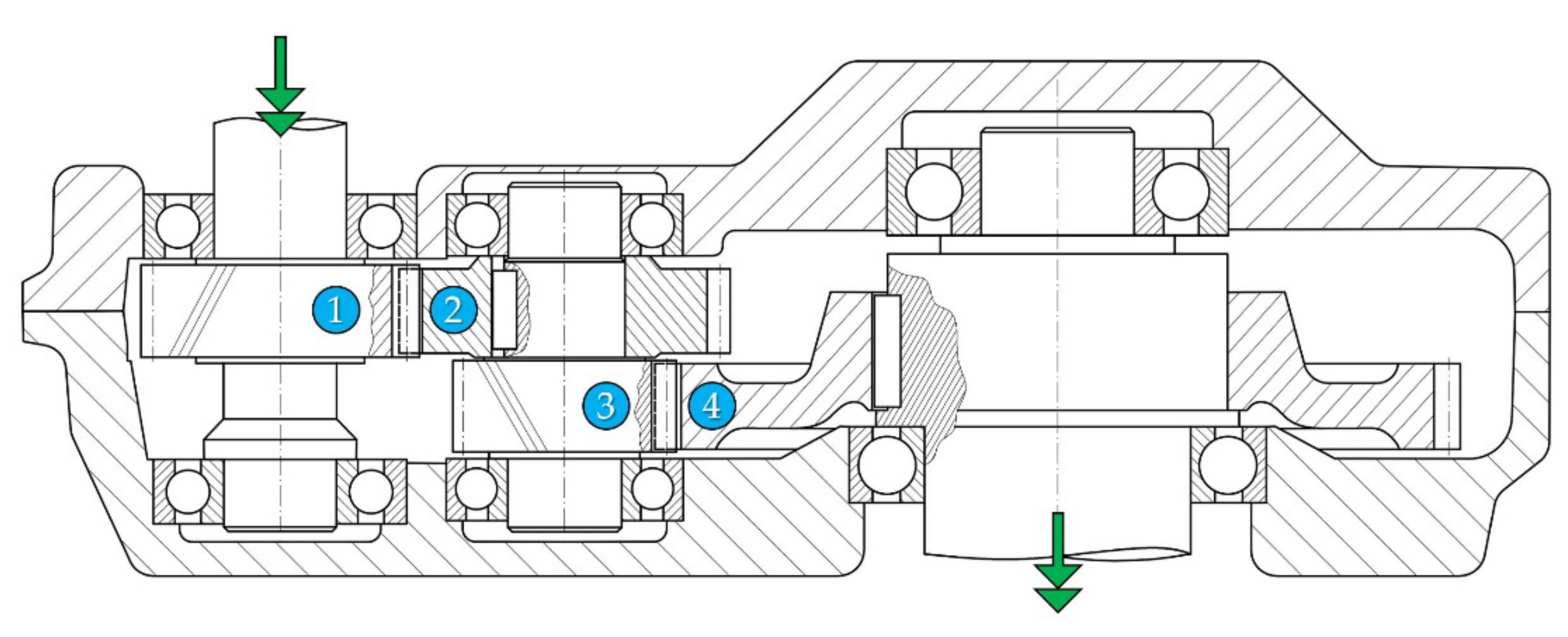
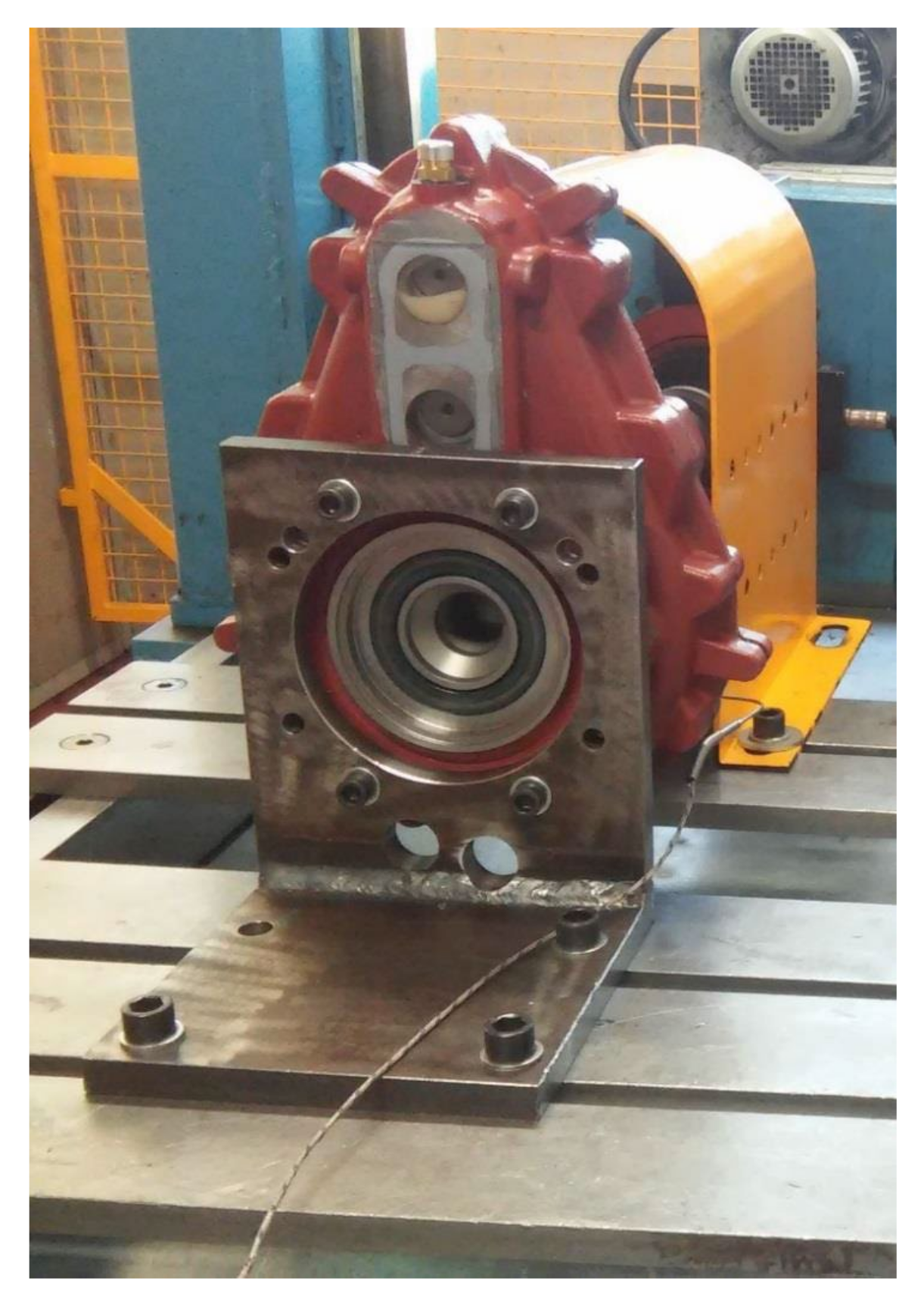
2. Materials
3. Methods
3.1. Mathematical Description
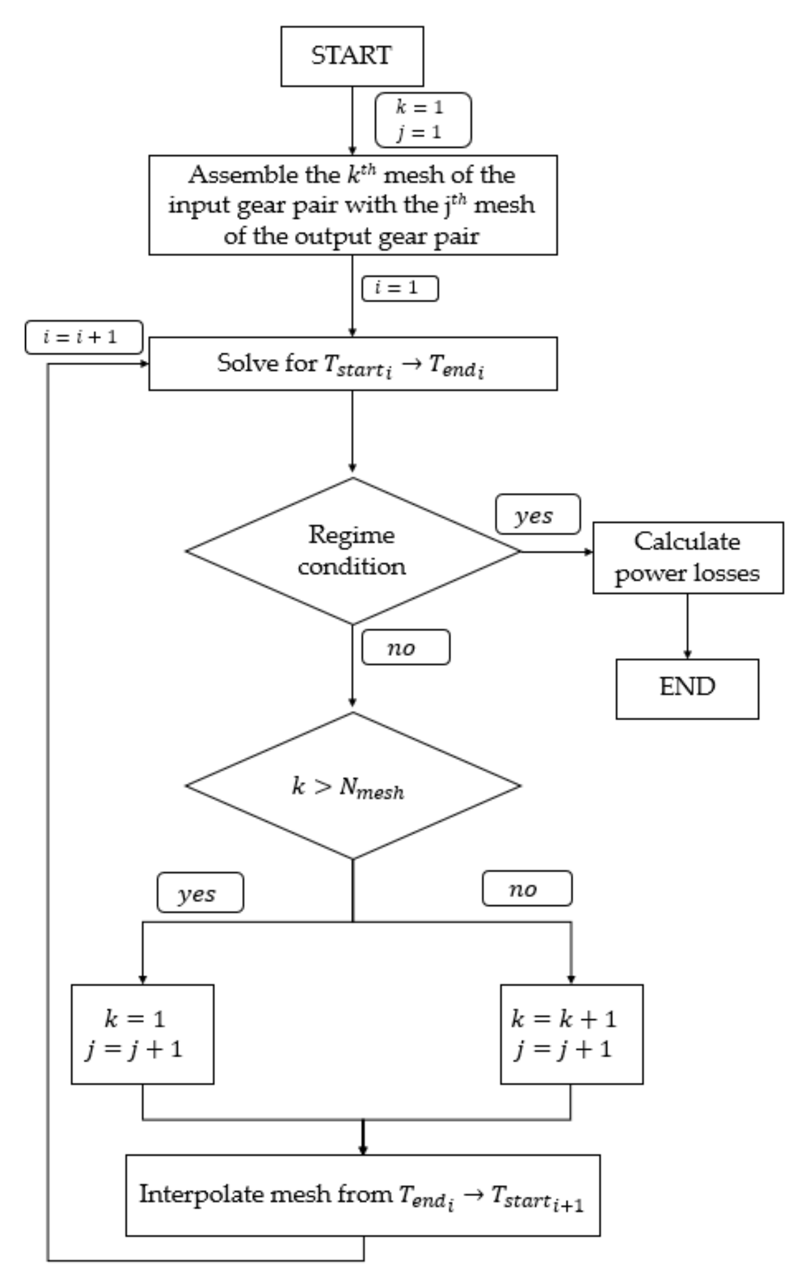
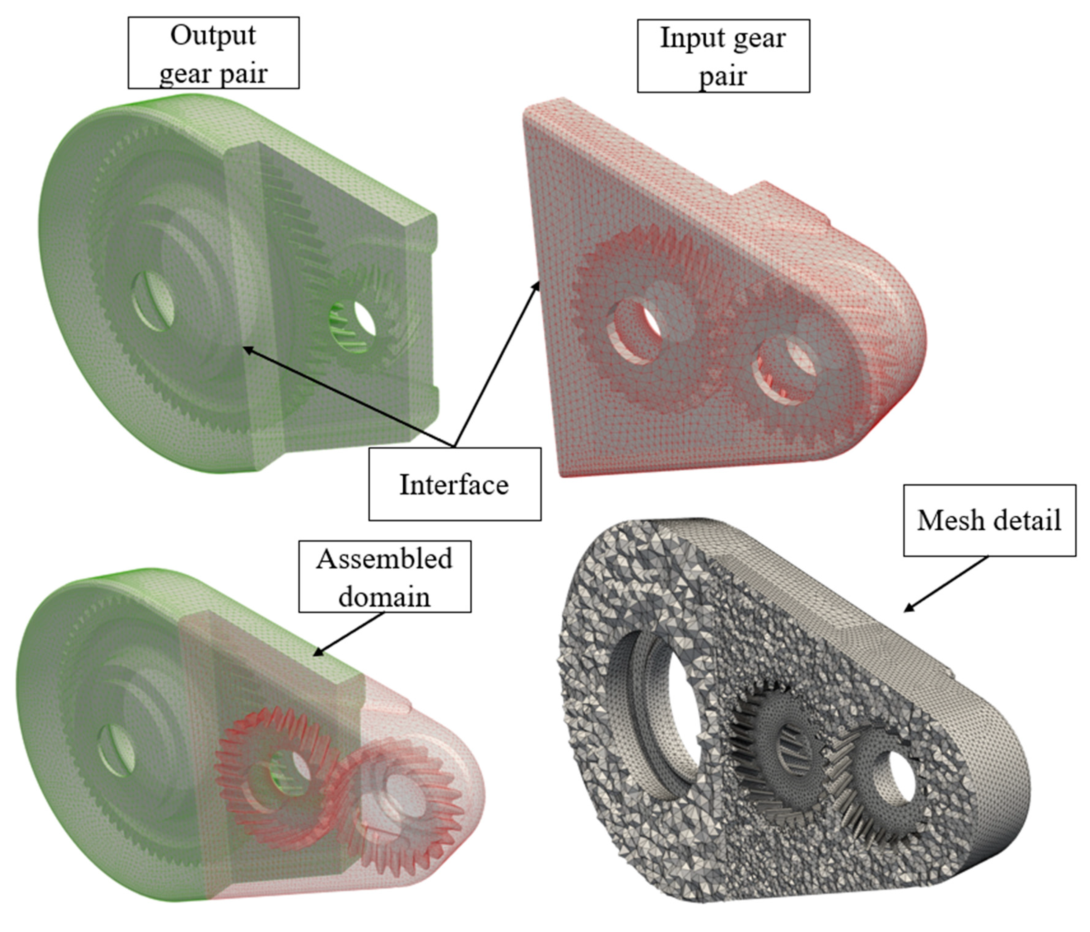
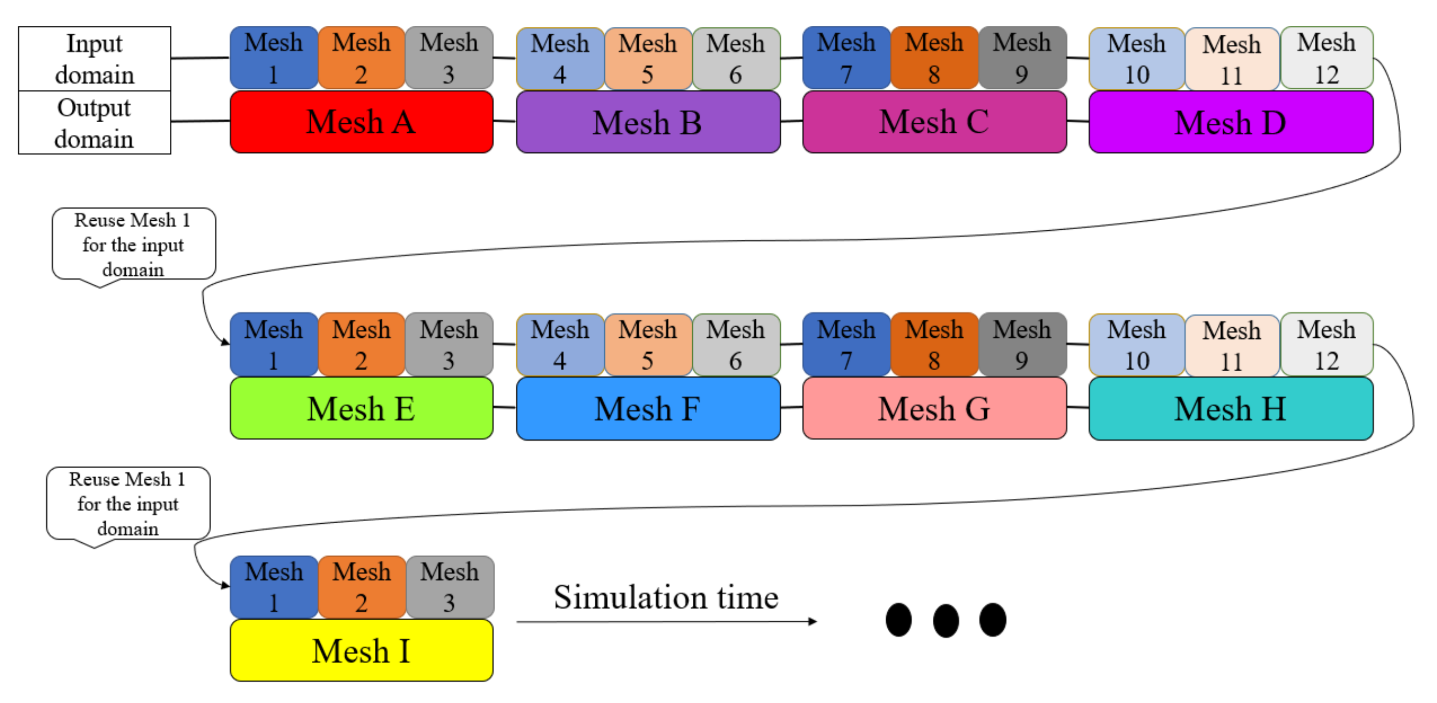
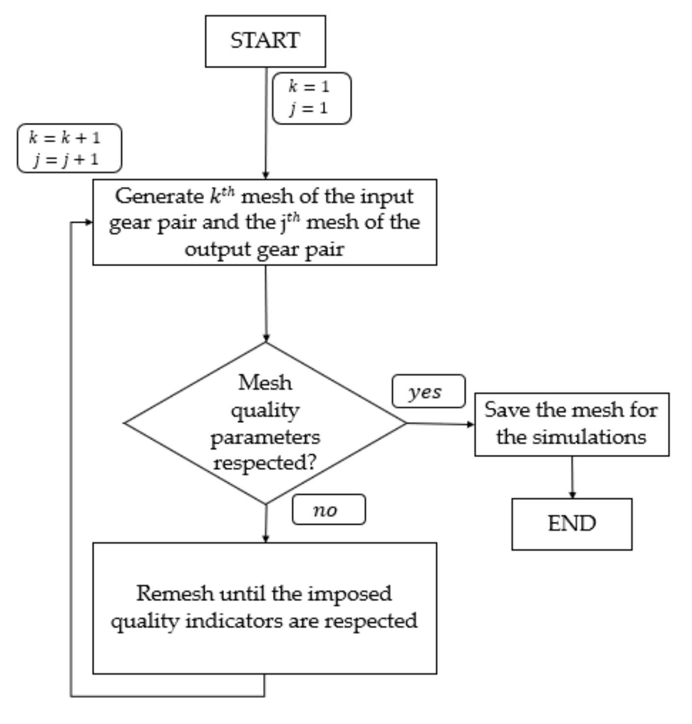
3.2. Numerical Approach
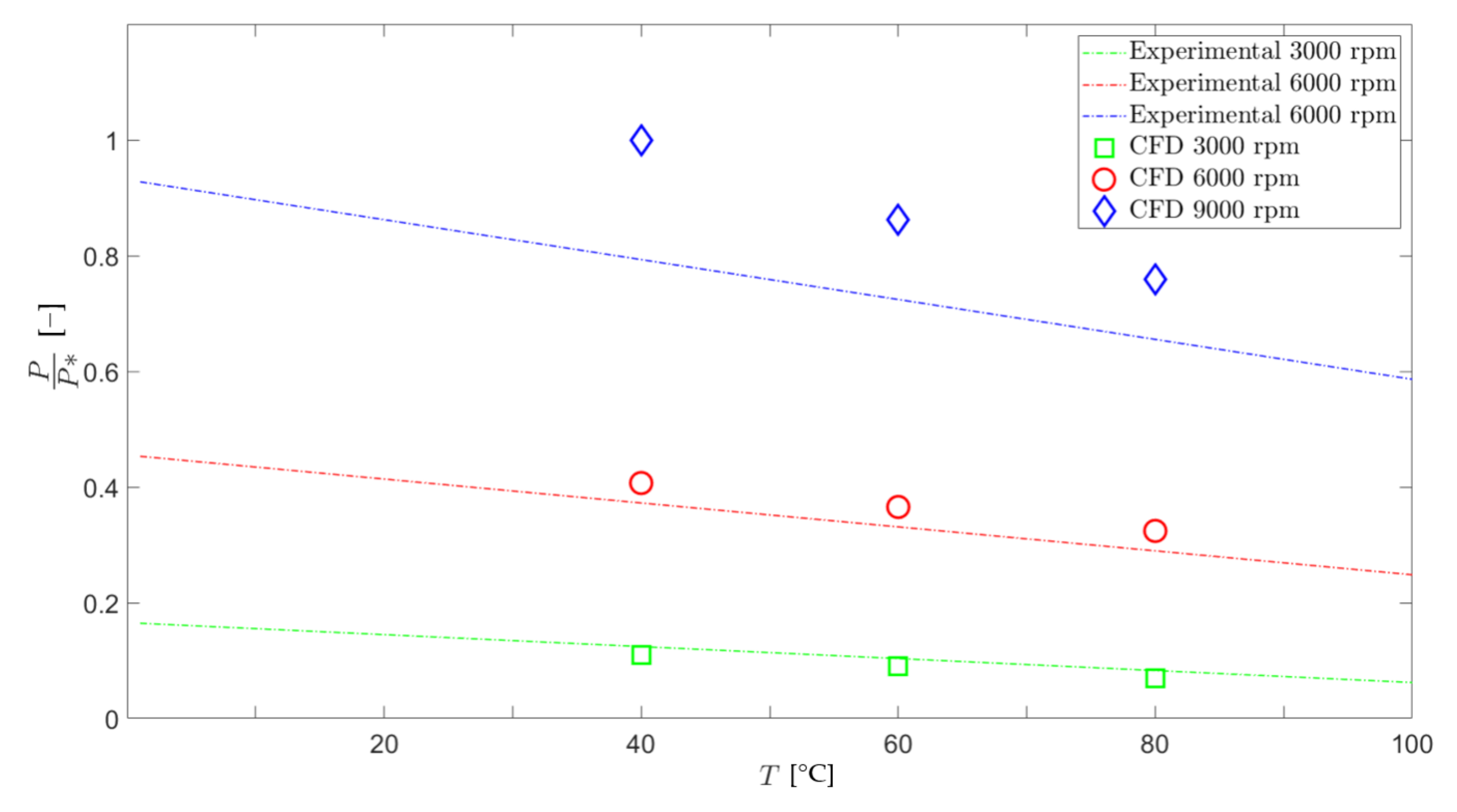
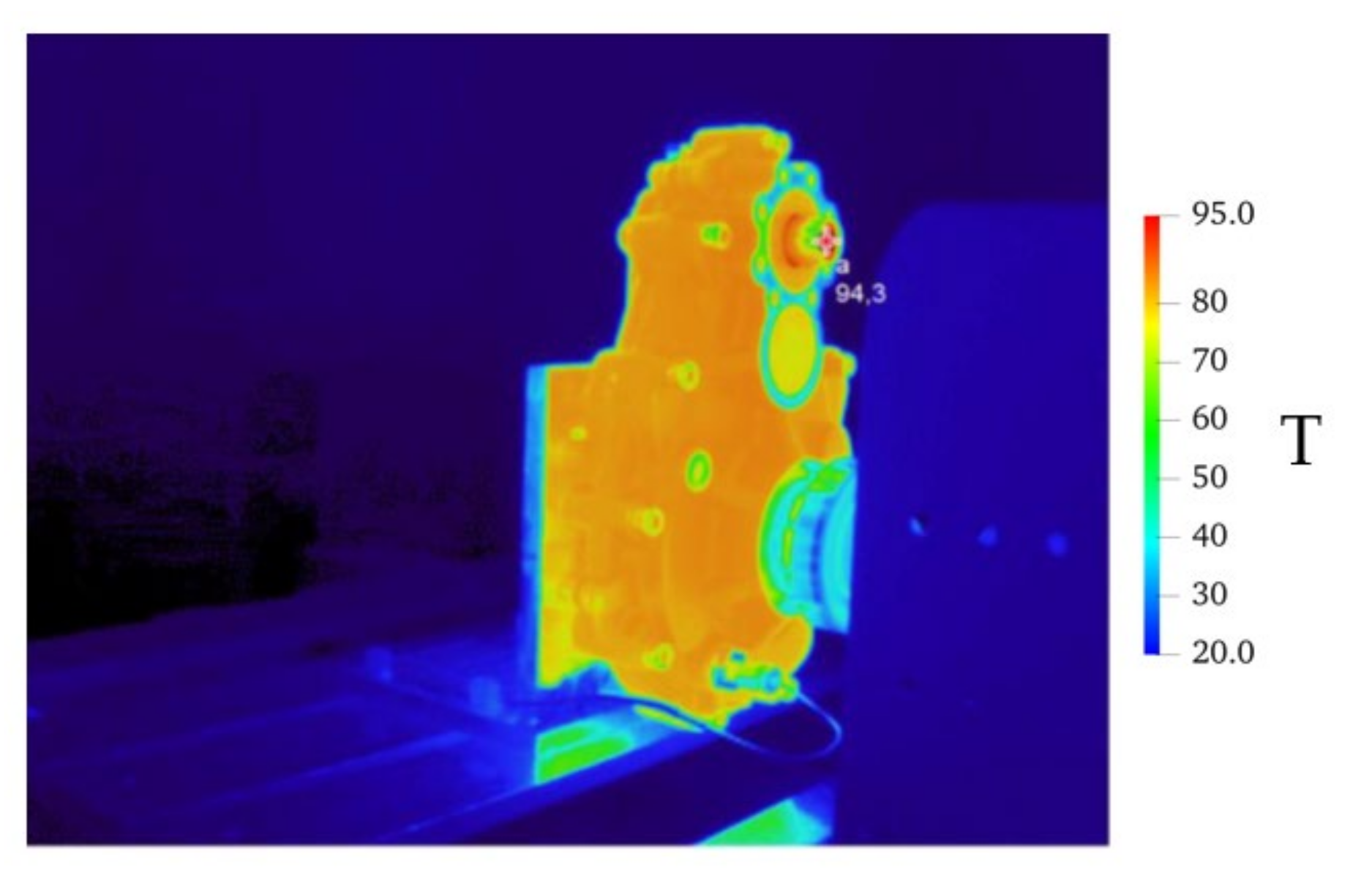
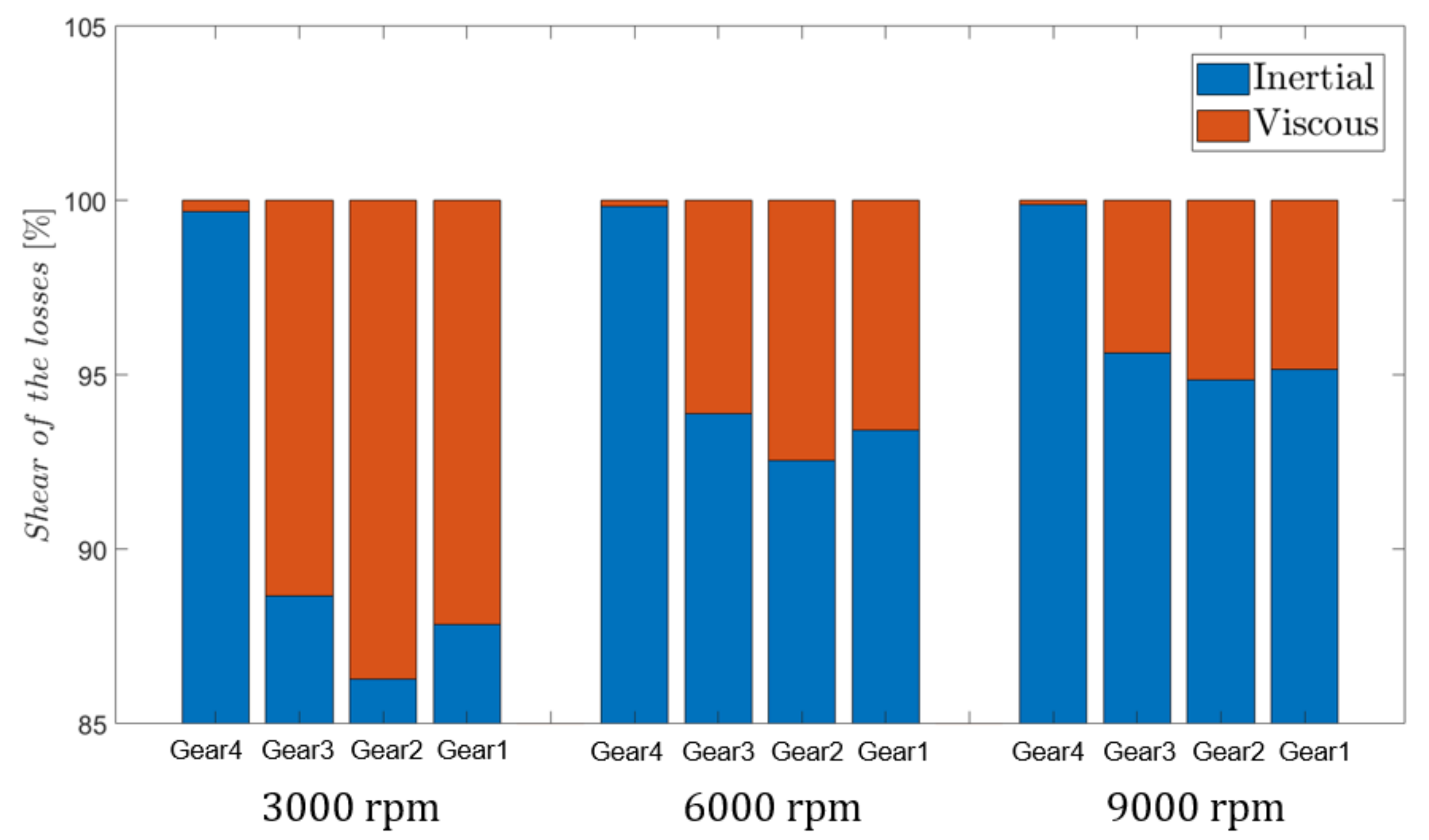
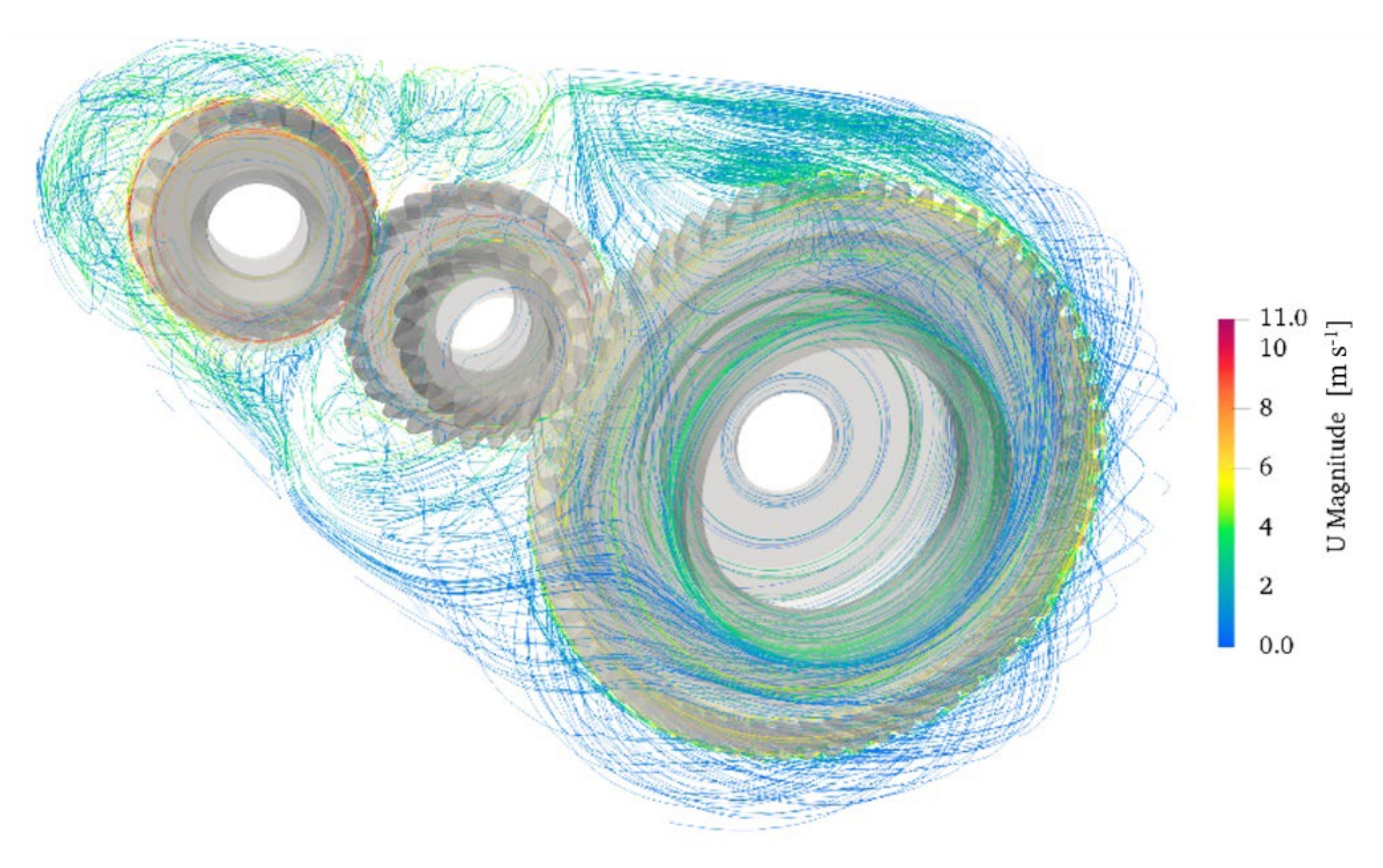
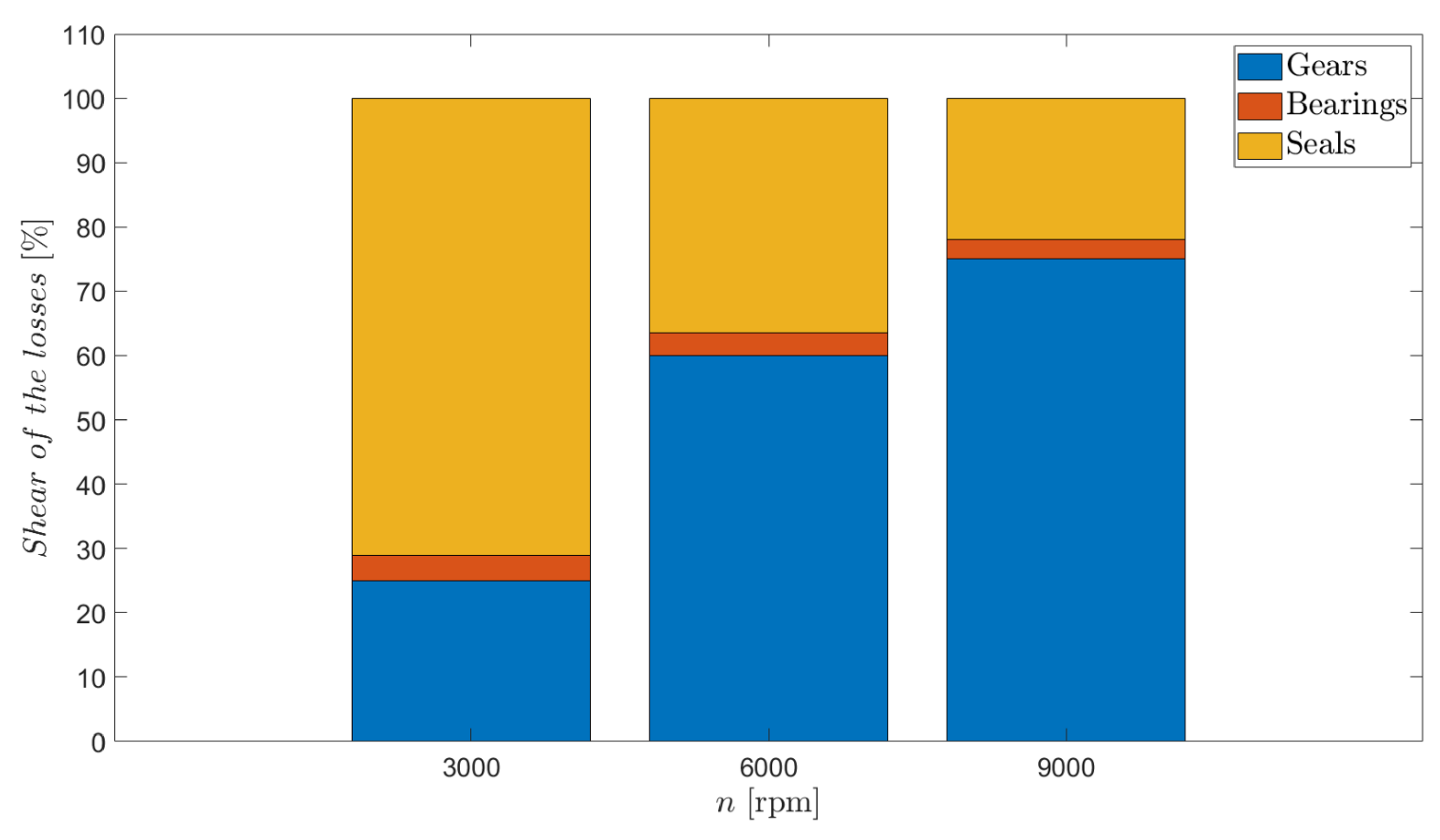
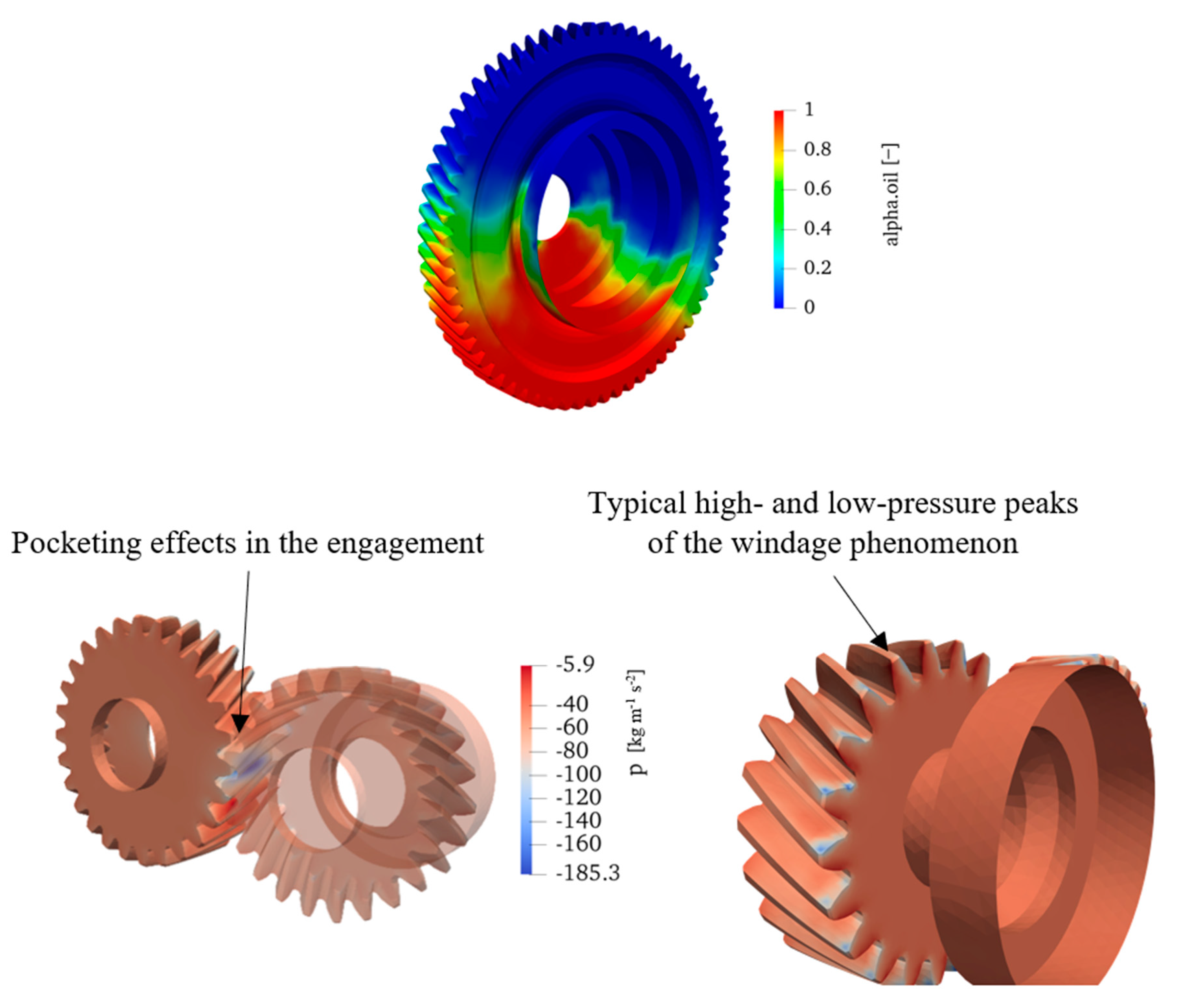
4. Results
5. Discussion
6. Conclusions
Author Contributions
Funding
Institutional Review Board Statement
Informed Consent Statement
Data Availability Statement
Acknowledgments
Conflicts of Interest
References
- Daily, J.; Nece, R. Chamber Dimension Effects of Induced Flow and Frictional Resistance of Enclosed Rotating Disks. ASME J. Basic Eng. 1960, 82, 217–232. [Google Scholar] [CrossRef]
- Mann, R.; Marston, C. Friction Drag on Bladed Disks in Housings as a Function of Reynolds Number, Axial and Radial Clearance, and Blade Aspect Ratio and Solidity. ASME J. Basic Eng. 1961, 83, 719–723. [Google Scholar] [CrossRef]
- Soo, S.L.; Princeton, N.J. Laminar Flow Over an Enclosed Rotating Disk. Trans. ASME 1958, 80, 287–296. [Google Scholar]
- Ohlendorf, H. Verlustleistung und Erwärmung von Stirnrädern; Technische Hochschule München: Munich, Germany, 1958. [Google Scholar]
- Mauz, W. Hydraulische Verluste von Strinradgetrieben bei Umfansgsgeschwindigkeiten bis 60 m/s; IMK: Stuttgart, Germany, 1987. [Google Scholar]
- Terekhov, A.S. Hydraulic Losses in Gearboxes With Oil Immersion. Vestn. Mashinostroeniya 1975, 55, 13–17. [Google Scholar]
- Walter, P. Untersuchung Zur Tauchschmierung Von Stirnrädern Bei Umfangsgeschwindigkeiten bis 60 m/s; Inst. für Maschinenkonstruktion u. Getriebebau, Univ.: Stuttgart, Germany, 1982. [Google Scholar]
- Changenet, C.; Velex, P. A Model for the Prediction of Churning Losses in Geared Transmissions—Preliminary Results. J. Mech. Des. 2007, 129, 128–133. [Google Scholar] [CrossRef]
- Changenet, C.; Leprince, G.; Ville, F.; Velex, P. A Note on Flow Regimes and Churning Loss Modeling. J. Mech. Des. 2011, 133, 1–5. [Google Scholar] [CrossRef]
- Seetharaman, S.; Kahraman, A.; Moorhead, M.D.; Petry-Johnson, T.T. Oil churning power losses of a gear pair: Experiments and model validation. J. Tribol. 2009, 131, 022202. [Google Scholar] [CrossRef]
- Quiban, R.; Changenet, C.; Marchesse, Y.; Ville, F.; Belmonte, J. Churning losses of spiral bevel gears at high rotational speed. Proc. Inst. Mech. Eng. Part J J. Eng. Tribol. 2019, 234, 172–182. [Google Scholar] [CrossRef]
- Laruelle, S.; Fossier, C.; Changenet, C.; Ville, F.; Koechlin, S. Experimental investigations and analysis on churning losses of splash lubricated spiral bevel gears. Mech. Ind. 2017, 18, 412. [Google Scholar] [CrossRef] [Green Version]
- Groenenboom, P.H.L.; Mettichi, M.Z.; Gargouri, Y. Simulating Oil Flow for Gearbox Lubrication using Smoothed Particle Hydrodynamics. Proc. Int. Conf. Gears 2015, 2015. [Google Scholar]
- Deng, X.; Wang, S.; Wang, S.; Wang, J.; Liu, Y.; Dou, Y.; He, G.; Qian, L. Lubrication mechanism in gearbox of high-speed railway trains. J. Adv. Mech. Des. Syst. Manuf. 2020, 14, JAMDSM0054. [Google Scholar] [CrossRef] [Green Version]
- Deng, X.; Wang, S.; Hammi, Y.; Qian, L.; Liu, Y. A combined experimental and computational study of lubrication mechanism of high precision reducer adopting a worm gear drive with complicated space surface contact. Tribol. Int. 2020, 146, 106261. [Google Scholar] [CrossRef]
- Morhard, B.; Schweigert, D.; Mileti, M.; Sedlmair, M.; Lohner, T.; Stahl, K. Efficient lubrication of a high-speed electromechanical powertrain with holistic thermal management. Forsch. Ingenieurwesen 2020, 85, 443–456. [Google Scholar] [CrossRef]
- Legrady, B.; Taesch, M.; Tschirschnitz, G.; Mieth, C.F. Prediction of churning losses in an industrial gear box with spiral bevel gears using the smoothed particle hydrodynamic method. Forsch. Ingenieurwesen 2021, 1–10. [Google Scholar] [CrossRef]
- Marchesse, Y.; Changenet, C.; Ville, F.; Velex, P. Investigations on CFD Simulations for Predicting Windage Power Losses in Spur Gears. J. Mech. Des. 2011, 133, 024501. [Google Scholar] [CrossRef]
- Chaari, F.; Romdhane, M.B.; Baccar, W.; Fakhfakh, T.; Haddar, M. Windage power loss in spur gear sets. WSEAS Trans. Appl. Theor. Mech. 2012, 7, 159–168. Available online: https://www.scopus.com/inward/record.uri?eid=2-s2.0-84857970703&partnerID=40&md5=92f96e3a4fb61d1509f0a57309f28764 (accessed on 2 December 2021).
- Pallas, S.; Marchesse, Y.; Changenet, C.; Ville, F.; Velex, P. Application and validation of a simplified numerical approach for the estimation of windage power losses in spur gears. Comput. Fluids 2013, 84, 39–45. [Google Scholar] [CrossRef]
- Dai, Y.; Ma, F.; Zhu, X.; Jia, J. Numerical Simulation Investigation on the Windage Power Loss of a High-Speed Face Gear Drive. Energies 2019, 12, 2093. [Google Scholar] [CrossRef] [Green Version]
- Cavotta, M.; Hotait, M.; Singh, A. A Computational Fluid Dynamics (CFD) Model for Gear Churning; SAE International: Warrendale, PA, USA, 2018. [Google Scholar] [CrossRef]
- Bianchini, C.; Da Soghe, R.; Giannini, L.; Fondelli, T.; Massini, D.; Facchini, B.; D’Errico, J. Load independent losses of an aeroengine epicyclic power gear train: Numerical investigation. In Proceedings of the ASME Turbo Expo 2019: Turbomachinery Technical Conference and Exposition, Phoenix, AZ, USA, 17–21 June 2019. [Google Scholar] [CrossRef]
- Liu, H.; Jurkschat, T.; Lohner, T.; Stahl, K. Detailed Investigations on the Oil Flow in Dip-Lubricated Gearboxes by the Finite Volume CFD Method. Lubricants 2018, 6, 47. [Google Scholar] [CrossRef] [Green Version]
- Liu, H.; Link, F.; Lohner, T.; Stahl, K. Computational fluid dynamics simulation of geared transmissions with injection lubrication. Proc. Inst. Mech. Eng. Part C J. Mech. Eng. Sci. 2019, 233, 7412–7422. [Google Scholar] [CrossRef]
- Hildebrand, L.; Dangl, F.; Sedlmair, M.; Lohner, T.; Stahl, K. CFD analysis on the oil flow of a gear stage with guide plate. Forsch. Ingenieurwesen 2021, 1–14. [Google Scholar] [CrossRef]
- International Organization for Standardization. ISO 14635-1, FZG Test Method A/8,3/90 for Relative Scuffing Load-Carrying Capacity of Oils. 14635-1; International Organization for Standardization: Geneva, Switzerland, 2000. [Google Scholar]
- Peng, Q.; Zhou, C.; Gui, L.; Fan, Z. Investigation of the lubrication system in a vehicle axle: Numerical model and experimental validation. Proc. Inst. Mech. Eng. Part D J. Automob. Eng. 2018, 233, 1232–1244. [Google Scholar] [CrossRef]
- Peng, Q.; Gui, L.; Fan, Z. Numerical and experimental investigation of splashing oil flow in a hypoid gearbox. Eng. Appl. Comput. Fluid Mech. 2018, 12, 324–333. [Google Scholar] [CrossRef] [Green Version]
- Peng, Q.; Zhou, C.; Gui, L.; Fan, Z. Investigation of the lubrication system in a vehicle axle: Optimization and experimental validation. Proc. Inst. Mech. Eng. Part D J. Automob. Eng. 2019, 233, 2096–2107. [Google Scholar] [CrossRef]
- Lu, F.; Wang, M.; Bao, H.; Huang, W.; Zhu, R. Churning power loss of the intermediate gearbox in a helicopter under splash lubrication. Proc. Inst. Mech. Eng. Part J J. Eng. Tribol. 2021, 236, 49–58. [Google Scholar] [CrossRef]
- Lu, F.; Wang, M.; Pan, W.; Bao, H.; Ge, W. CFD-Based Investigation of Lubrication and Temperature Characteristics of an Intermediate Gearbox with Splash Lubrication. Appl. Sci. 2021, 11, 352. [Google Scholar] [CrossRef]
- Dai, Y.; Jia, J.; Ouyang, B.; Bian, J. Determination of an Optimal Oil Jet Nozzle Layout for Helical Gear Lubrication: Mathematical Modeling, Numerical Simulation, and Experimental Validation. Complexity 2020, 2020, 2187027. [Google Scholar] [CrossRef]
- Deshpande, S.; Joshi, H.; Madhavan, J.; Mason, P.; Wink, C. Two-Way Coupled CFD Approach for Predicting Gear Temperature of Oil Jet Lubricated Transmissions. SAE Int. J. Commer. Veh. 2018, 11, 163–170. [Google Scholar] [CrossRef]
- Mastrone, M.N.; Concli, F. Power Losses of Spiral Bevel Gears: An Analysis Based on Computational Fluid Dynamics. Front. Mech. Eng. 2021, 7. [Google Scholar] [CrossRef]
- OpenFOAM. Available online: http://www.openfoam.com (accessed on 2 December 2021).
- Versteeg, H.K.; Malalasekera, W. An Introduction to Computational Fluid Dynamics—The Finite Volume Method; Pearson Education: London, UK, 1995. [Google Scholar]
- Hirt, C.W.; Nichols, B.D. Volume of fluid (VOF) method for the dynamics of free boundaries. J. Comput. Phys. 1981, 39, 201–225. [Google Scholar] [CrossRef]
- Mastrone, M.N.; Concli, F. CFD simulation of grease lubrication: Analysis of the power losses and lubricant flows inside a back-to-back test rig gearbox. J. Non-Newtonian Fluid Mech. 2021, 297, 104652. [Google Scholar] [CrossRef]
- Mastrone, M.N.; Hartono, E.A.; Chernoray, V.; Concli, F. Oil distribution and churning losses of gearboxes: Experimental and numerical analysis. Tribol. Int. 2020, 151, 106496. [Google Scholar] [CrossRef]
- Mastrone, M.N.; Concli, F. CFD simulations of gearboxes: Implementation of a mesh clustering algorithm for efficient simulations of complex system’s architectures. Int. J. Mech. Mater. Eng. 2021, 16, 1–19. [Google Scholar] [CrossRef]
- Mastrone, M.N.; Concli, F. Development of a mesh clustering algorithm aimed at reducing the computational effort of gearboxes’ CFD simulations. In Boundary Elements and other Mesh Reduction Methods XLIV; WIT Press: Southampton, UK, 2021; Volume 131, pp. 59–69. [Google Scholar] [CrossRef]
- SALOME. Available online: https://www.salome-platform.org (accessed on 2 December 2021).
- Python. Available online: https://www.python.org/ (accessed on 2 December 2021).
- Netgen. Available online: https://gitlab.asc.tuwien.ac.at/jschoeberl/ngsolve-docu/wikis/home (accessed on 2 December 2021).
- Bash. Available online: www.gnu.org/software/bash (accessed on 2 December 2021).
- ISO 14179-1; Gears—Thermal capacity—Part 1: Rating Gear Drives with Thermal Equilibrium at 95 °C Sump Temperature. 14179-1. International Organization for Standardization: Geneva, Switzerland, 2001.
- Maccioni, L.; Chernoray, V.G.; Mastrone, M.N.; Bohnert, C.; Concli, F. Study of the impact of aeration on the lubricant behavior in a tapered roller bearing: Innovative numerical modelling and validation via particle image velocimetry. Tribol. Int. 2022, 165, 107301. [Google Scholar] [CrossRef]


| Characteristic | Unit | Gear 1 | Gear 2 | Gear 3 | Gear 4 |
|---|---|---|---|---|---|
| Normal module | mm | 2.65 | 2.65 | 2.65 | 2.65 |
| Number of teeth | - | 22 | 27 | 17 | 66 |
| Pressure angle | 18 | 18 | 18 | 18 | |
| Helix angle | 28 | 28 | 30 | 30 | |
| Face width | mm | 24 | 22 | 24 | 22 |
| Property | Unit | Value |
|---|---|---|
| Density at 15 °C | kg/m3 | 882 |
| Kinematic viscosity at 40 °C | mm2/s | 60 |
| Kinematic viscosity at 100 °C | mm2/s | 9.4 |
| Viscosity index | - | 138 |
| Flash point | °C | 220 |
| Pour point | °C | −42 |
Publisher’s Note: MDPI stays neutral with regard to jurisdictional claims in published maps and institutional affiliations. |
© 2022 by the authors. Licensee MDPI, Basel, Switzerland. This article is an open access article distributed under the terms and conditions of the Creative Commons Attribution (CC BY) license (https://creativecommons.org/licenses/by/4.0/).
Share and Cite
Mastrone, M.N.; Concli, F. A Multi Domain Modeling Approach for the CFD Simulation of Multi-Stage Gearboxes. Energies 2022, 15, 837. https://doi.org/10.3390/en15030837
Mastrone MN, Concli F. A Multi Domain Modeling Approach for the CFD Simulation of Multi-Stage Gearboxes. Energies. 2022; 15(3):837. https://doi.org/10.3390/en15030837
Chicago/Turabian StyleMastrone, Marco Nicola, and Franco Concli. 2022. "A Multi Domain Modeling Approach for the CFD Simulation of Multi-Stage Gearboxes" Energies 15, no. 3: 837. https://doi.org/10.3390/en15030837
APA StyleMastrone, M. N., & Concli, F. (2022). A Multi Domain Modeling Approach for the CFD Simulation of Multi-Stage Gearboxes. Energies, 15(3), 837. https://doi.org/10.3390/en15030837