
Effect of Ground Electrodes on the Susceptibility to Damage of Customer Premises Equipment (CPE) under Impulse Conditions


Abstract
:1. Introduction
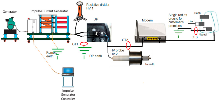
2. Test Arrangement
2.1. Impulse Test Equipment
2.2. Testing Sites
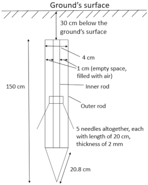
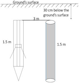
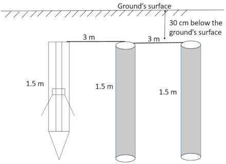
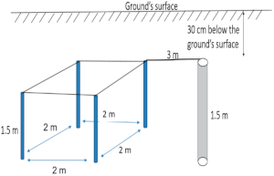
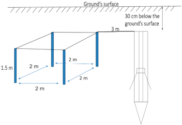
2.3. Ground Electrodes
3. Test Results
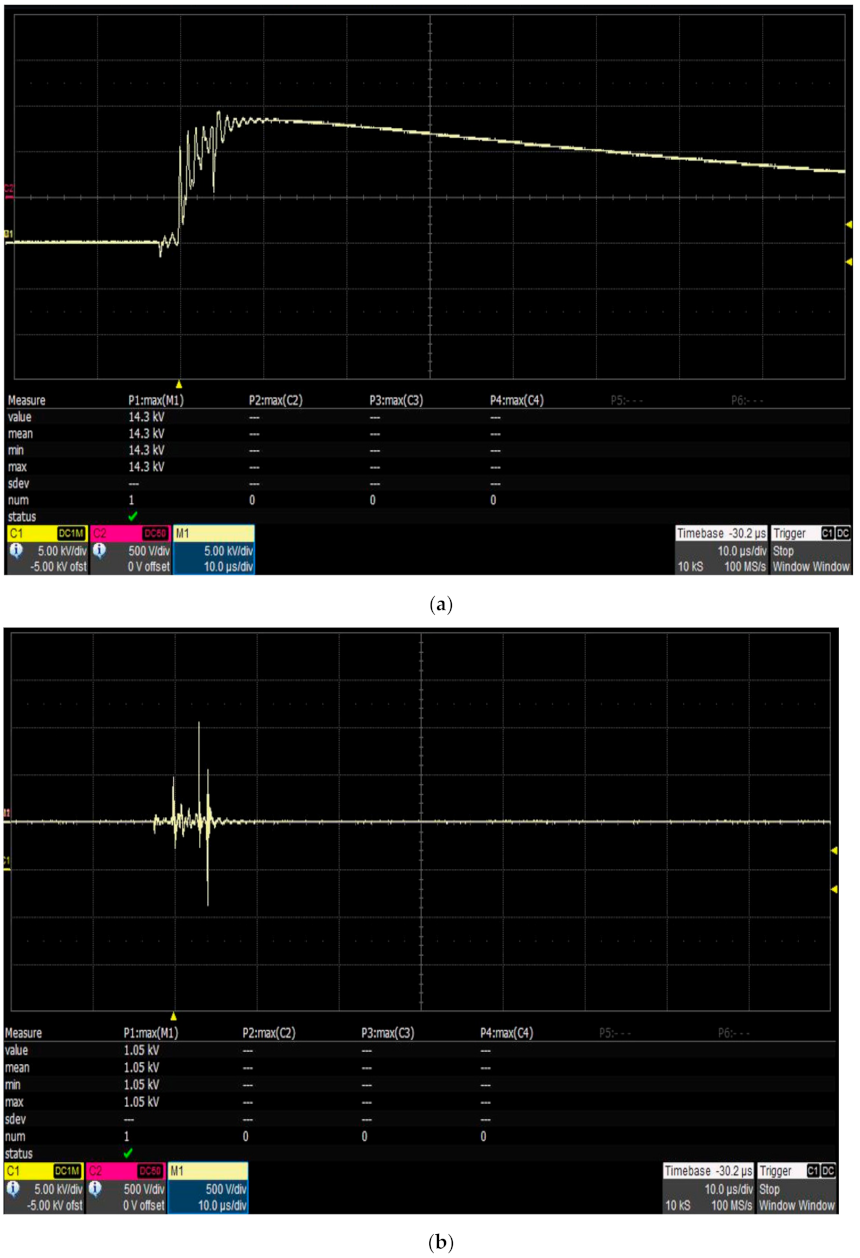
3.1. Measurements from Voltage Divider 1 and Current Transformer 1
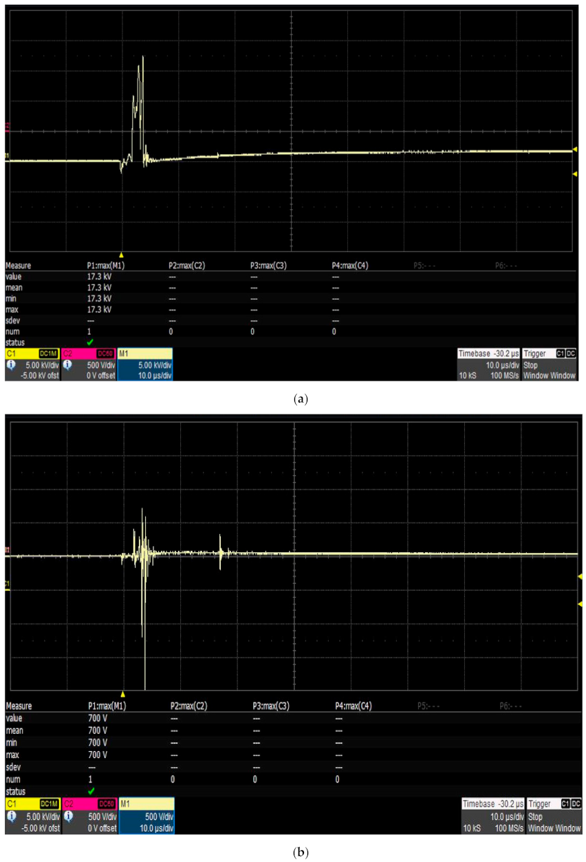
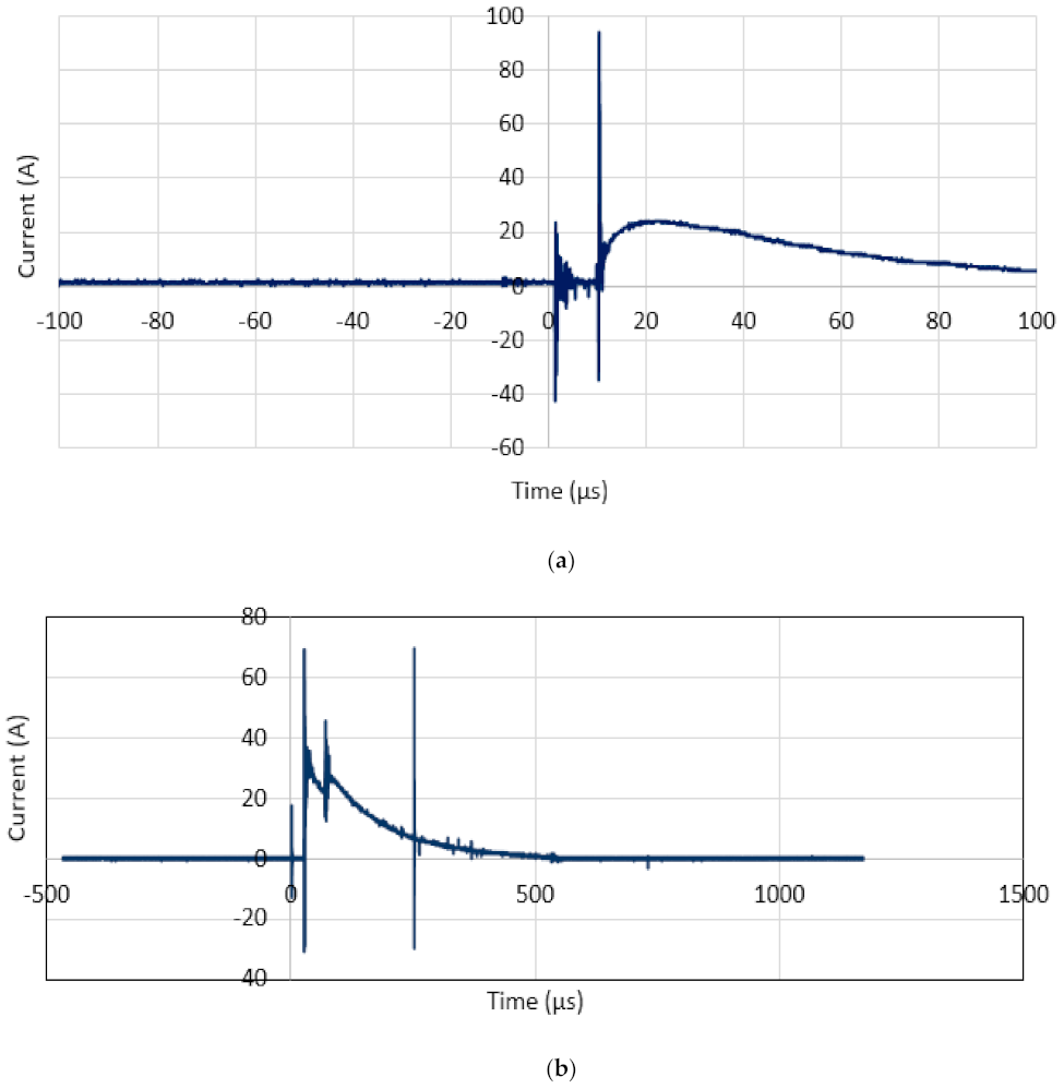
3.2. Measurements from Voltage Divider 2 and Current Transformers 2 and 3
4. Conclusions
Author Contributions
Funding
Institutional Review Board Statement
Informed Consent Statement
Data Availability Statement
Conflicts of Interest
References
- IEEE. IEEE Guide for Safety in AC Substation Grounding; Std 80-2013; IEEE: Piscataway, NJ, USA, 2013. [Google Scholar]
- International Telecommunication Union (ITU) Standard. SERIES K: Protection of Customer Premises from Overvoltages; K. 66; ITU-T: Geneva, Switzerland, 2019. [Google Scholar]
- Hidaka, T.; Ishimoto, K.; Asakawa, A.; Shiota, K. Relationship between Grounding Resistance Connected to Surge Arresters and Lightning Surge Behavior Observed in Low-Voltage Equipment. In Proceedings of the International Symposium on Lightning Protection (XII SIPDA), Belo Horizonte, Brazil, 7–11 October 2013. [Google Scholar]
- ITU-T. Series K: Protection Against Interference, Resistibility of Telecommunication Equipment Installed in Customer Premises to Overvoltages and Overcurrents; K.21; ITU-T: Geneva, Switzerland, 2019. [Google Scholar]
- Ramli, A.; Jamlus, N.; Ibrahim, A.; Amiruddin, F. Resistive Coupling Effect to Customer Premises Equipment (CPE) due to Non-Equipotential Earthing System. In Proceedings of the IEEE International Conference on High Voltage Engineering and Application (ICHVE), Athens, Greece, 10–13 September 2018. [Google Scholar]
- Abdul Ali, A.; Ahmad, N.; Mohamad Nor, N.; Reffin, M.; Syed Abdullah, S. Investigations on the Performance of a New Grounding Device with Spike Rods under High Magnitude Current Conditions. Energies 2019, 12, 1138. [Google Scholar] [CrossRef] [Green Version]
- Abdul Ali, A.; Ahmad, N.; Mohamad Nor, N. Effect of Impulse Polarity on a New Grounding Device with Spike Rods (GDSR). Energies 2020, 13, 4672. [Google Scholar] [CrossRef]
- Lundgaard, L.; Linhjell, D.; Berg, G. Propagation of Positive and Negative Streamers in Oil with and without Pressboard Interfaces. IEEE Trans. Dielectr. Electr. Insul. 1998, 5, 388–395. [Google Scholar] [CrossRef]
- Kuffel, E.; Zaengl, W.S.; Kuffel, J. High Voltage Engineering: Fundamentals; Butterworth-Heinemann: New Delhi, India, 2000. [Google Scholar]
- ANSI/TIA/EIA 568-B: Commercial Building Telecommunications Cabling Standard; Cablingdb: Hochiminh City, Vietnam, 2015.
- BS7430-2011: Code of Practice for Protective Earthing of Electrical Installations; British Standards Institution: London, UK, 2011.
- Sekioka, S. Frequency and Current-Dependent Grounding Resistance Model for Lightning Surge Analysis. IEEE Trans. Electromagn. Compat. 2018, 61, 419–425. [Google Scholar] [CrossRef]
- Harid, N.; Griffiths, H.; Mousa, S.; Clark, D.; Robson, S.; Haddad, A. On the Analysis of Impulse Test Results on Grounding Systems. IEEE Trans. Ind. Appl. 2015, 51, 5324–5334. [Google Scholar] [CrossRef]


| Site | Upper Layer Soil Resistivity | Lower Layer Soil Resistivity | Height of Upper Layer (m) | Height of Lower Layer (m) |
|---|---|---|---|---|
| 1 | 84.96 | 892 | 12.54 | Inf |
| 2a and 2b | 78.41 | 126.36 | 1.84 | Inf |
| Configuration | RDC Values (Ω) | ||
|---|---|---|---|
| Site 1 | Site 2a | Site 2b | |
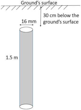 (a) Single rod electrode | 46.0 | 150.8 | 103.1 |
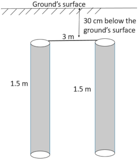 (b) 2-rod electrode | 30.9 | 78.7 | |
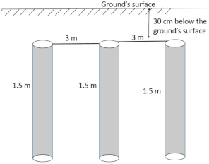 (c) 3-rod electrode | 14.3 | 42.2 | |
 (d) Grounding devices with spike rods (GDSR) | 31.4 | 88.5 | 69.1 |
 (e) GDSR with single rod electrode | 19.2 | 49.8 | |
 (f) GDSR with 2-rod electrodes | 14.2 | 34.6 | |
 (g) 2 m × 2 m electrode with single rod electrode | 39.7 | ||
 (h) 2 m × 2 m electrode with GDSR | 34.2 | ||
| Conf. | RDC (Ω) | Impulse Impedance Values (Ω) | Percentage Difference Between RDC | ||||||||||
|---|---|---|---|---|---|---|---|---|---|---|---|---|---|
| and Zimpulse (%) | |||||||||||||
| Site 1 | Site 2a | Site 2b | Site 1 | Site 2a | Site 2b | Site 1 | Site 2a | Site 2b | |||||
| + | − | + | − | + | + | − | + | − | + | ||||
| (a) | 46 | 150.8 | 103.1 | 13.5 | 13.4 | 24.6 | 25.4 | 38.5 | 70.65 | 70.87 | 83.69 | 83.16 | 62.66 |
| (b) | 30.9 | 78.7 | 8.2 | * | 16.9 | * | 73.46 | * | 78.53 | * | |||
| (c) | 14.3 | 42.2 | 5.7 | * | 11.1 | 11.5 | 60.14 | * | 73.7 | 72.75 | |||
| (d) | 31.4 | 88.5 | 69.1 | 12.2 | 12.8 | 22.1 | 19.6 | 20.82 | 61.15 | 59.24 | 75.03 | 77.85 | 69.9 |
| (e) | 19.2 | 49.8 | 8.8 | 8.1 | 15.3 | 14.4 | 54.17 | 57.81 | 69.28 | 71.08 | |||
| (f) | 14.2 | 34.6 | 6.3 | 6.4 | 10.8 | 10.6 | 55.63 | 54.93 | 68.79 | 69.36 | |||
| (g) | 39.7 | 12.97 | 67.33 | ||||||||||
| (h) | 34.2 | 15.2 | 55.56 | ||||||||||
 No damage to the modem is observed.
| Site/ Conf./RDC Values | Impulse Polarity | Voltage on the Modem, V2 (kV) | Current through the Modem, CT2 (A) | Condition of the Modem after the Tests | Current on the Power Adapter, CT3 (A) | Condition Fulfilment |
|---|---|---|---|---|---|---|
| Site 1 (a), 46 Ω | Positive | 8 | 28 | Working | 26.4 | Fulfilling condition (i) voltage at the modem is below 15 kV, and the current magnitudes is below 35 A. |
| Negative | −8 | −33.6 | Working | −34.4 | Fulfilling condition (i) voltage at the modem is below 15 kV, and the current magnitudes is below 35 A. | |
| Site 1 (b), 30.9 Ω | Positive | 14.8 | 20 | Working | 22.4 | Fulfilling condition (i) voltage at the modem is below 15 kV, and the current magnitudes is below 35 A |
| Negative | No triggering achieved at 30 kV | |||||
| Site 1 (c), 14.3 Ω | Positive | 13 | 20 | Working | 0 | Fulfilling condition (i) voltage at the modem is below 15 kV, and the current magnitudes is below 35 A. |
| Negative | No triggering achieved at 30 kV | |||||
| Site 1 (d), 31.4 Ω | Positive | 4 | 60 | Damaged | 24.4 | Not fulfilling any of the three conditions |
| Negative | −16.4 | −62.4 | Damaged | −28.4 | Not fulfilling any of the three conditions | |
| Site 1 (e), 19.2 Ω | Positive | 13.2 | 1.6 | Working | 0 | Fulfilling condition (i) voltage at the modem is below 15 kV, and the current magnitudes is below 35 A. |
| Negative | −13.2 | −23.2 | Working | −25.2 | Fulfilling condition (i) voltage at the modem is below 15 kV, and the current magnitudes is below 35 A. | |
| Site 1 (f), 14.2 Ω | Positive | 12 | 1.6 | Working | 0 | Fulfilling condition (i) voltage at the modem is below 15 kV, and the current magnitudes is below 35 A. |
| Negative | −16 | −3.6 | Working | 0 | (ii) voltage on the modem is higher than15 kV, but the current is below 5 A. | |
| Site 2a (a), 150.8 Ω | Positive | 6.2 | 244 | Damaged | 30 | Not fulfilling any of the three conditions |
| Negative | −7.2 | −236 | Damaged | −38 | Not fulfilling any of the three conditions | |
| Site 2a (b), 78.7 Ω | Positive | 15 | 3640 | Damaged | 0 | Not fulfilling any of the three conditions |
| Negative | No triggering achieved at 30 kV | |||||
| Site 2a (c), 42.2 Ω | Positive | 12 | 23 | Working | 23 | Fulfilling condition (i) voltage at the modem is below 15 kV, and the current magnitudes is below 35 A. |
| Negative | −14.4 | −22.4 | Working | 0 | Fulfilling condition (i) voltage at the modem is below 15 kV, and the current magnitudes is below 35 A. | |
| Site 2a (d), 88.5 Ω | Positive | 5 | 200 | Damaged | 25 | Not fulfilling any of the three conditions |
| Negative | −16 | −40 | Damaged | −42 | Not fulfilling any of the three conditions | |
| Site 2a (e), 49.8 Ω | Positive | 14 | 220 | Damaged | 28 | Not fulfilling any of the three conditions |
| Negative | −14 | −308 | Damaged | −28 | Not fulfilling any of the three conditions | |
| Site 2a (f), 34.6 Ω | Positive | 5 | 80 | Damaged | 20 | Not fulfilling any of the three conditions |
| Negative | −2 | −126.4 | Working | −26 | Fulfilling condition (iii) higher current magnitudes, more than 35 A, but the voltage at the modem is not more than 2 kV | |
| Site 2b (a), 103.1 Ω | Positive | 17.2 | 0 | Damaged | Not measured | Not fulfilling any of the three conditions |
| Site 2b (d), 69.1 Ω | Positive | 17.3 | 0 | Damaged | Not measured | Not fulfilling any of the three conditions |
| Site 2b (g), 39.7 Ω | Positive | 16.7 | 0 | Damaged | Not measured | Not fulfilling any of the three conditions |
| Site 2b (h), 34.2 Ω | Positive | 14.3 | 0 | Working | Not measured | Fulfilling condition (i) voltage at the modem is below 15 kV, and the current magnitudes is below 35 A. |
Publisher’s Note: MDPI stays neutral with regard to jurisdictional claims in published maps and institutional affiliations. |
© 2022 by the authors. Licensee MDPI, Basel, Switzerland. This article is an open access article distributed under the terms and conditions of the Creative Commons Attribution (CC BY) license (https://creativecommons.org/licenses/by/4.0/).
Share and Cite
Muhammad, U.; Mohamad Nor, N.; Ramli, A.M.; Ahmad, N.N. Effect of Ground Electrodes on the Susceptibility to Damage of Customer Premises Equipment (CPE) under Impulse Conditions. Energies 2022, 15, 1247. https://doi.org/10.3390/en15031247
Muhammad U, Mohamad Nor N, Ramli AM, Ahmad NN. Effect of Ground Electrodes on the Susceptibility to Damage of Customer Premises Equipment (CPE) under Impulse Conditions. Energies. 2022; 15(3):1247. https://doi.org/10.3390/en15031247
Chicago/Turabian StyleMuhammad, Usman, Normiza Mohamad Nor, Annuar Mohd Ramli, and Nurul Nadia Ahmad. 2022. "Effect of Ground Electrodes on the Susceptibility to Damage of Customer Premises Equipment (CPE) under Impulse Conditions" Energies 15, no. 3: 1247. https://doi.org/10.3390/en15031247
APA StyleMuhammad, U., Mohamad Nor, N., Ramli, A. M., & Ahmad, N. N. (2022). Effect of Ground Electrodes on the Susceptibility to Damage of Customer Premises Equipment (CPE) under Impulse Conditions. Energies, 15(3), 1247. https://doi.org/10.3390/en15031247