Abstract
In this study, we investigated the applicability of an automobile shredder residue (ASR) as an energy and recycling resource. First, ASR gasification was conducted in a fixed-bed reactor (throughput = 1 kg/h) at different temperatures (800, 1000, and 1200 °C) and an equivalence ratio of 0.1–0.5. Clay bricks were prepared with the solid residue obtained from the gasification process to address the issue of solid-residue production in pyrolysis. The syngas (H2 + CO) from ASR gasification had maximum and minimum yields of approximately 86 and 40 vol.%, respectively. Furthermore, the yield of syngas increased with the temperature and equivalence ratio (ER); therefore, the optimum conditions for the ASR gasification were determined to be a temperature of 1200 °C and an ER of 0.5. In addition, solid residues, such as char and ash, began to melt due to thermal heating in the range of 1300–1400 °C and were converted into melting slag, which was subsequently used to manufacture clay bricks. The absorption ratios and compressive strengths of the clay bricks were compared to those set by Korean Industrial Standards to evaluate the quality of the clay bricks. As a result, the manufactured clay bricks were estimated to have a compressive strength of over 22.54 N/mm2 and an absorption ratio of less than 10%. Additionally, greenhouse gas (GHG) emissions from the melting–gasification process were estimated and compared with those from ASR incineration, calculated using the greenhouse gas equations provided by the Korean Ministry of Environment. As a result, it was revealed that the GHG emissions from the combined melting–gasification process (gasification, melting system, and clay-brick manufacturing) were approximately ten times higher than those from the ASR-incineration process. Thus, in terms of operation cost on the carbon capture process for GHG reduction, the combined melting–gasification process would be a more efficient process than that of incineration.
1. Introduction
Recently, waste-to-energy technology using municipal solid waste has been widely applied in renewable energy production, which is an alternative to fossil fuels [1]. However, municipal solid waste is heterogeneous and typically contains a high level of moisture. Therefore, recent studies have focused on developing technologies to produce a more efficient and sustainable form of renewable energy from solid and other types of waste. On the other hand, the annual cumulative production of plastics by 2015 was approximately 8300 Mt worldwide, and a proportion (7 wt.%) is used in the vehicle-manufacturing process. Additionally, with regard to the supplying trend of the plastic, the amount of the waste-plastics (7910 thousand ton) increased by around 1.76 times, compared with 2008 in Korea [2,3]. Recently, it has been found that automobile shredder residues (ASR), containing various metal and non-metal materials, are more stable and homogeneous than municipal solid waste, and ASR also contain more combustible compounds that can be used as fuel. In Korea, since the late 1990s, standards of air pollutant emissions, which limit the emission of carbon monoxide, nitrogen oxides, PM10, and hydrocarbon compounds, have been strictly enforced under the Act for Resource Recycling of Electrical and Electronic Equipment and Vehicles. Since the ASR became an alternative energy source in the 2000s, owing to fossil-fuel depletion, an end-of-life vehicle (ELV) directive was instituted to regulate emission pollutants generated during the recycling of these materials [4].
Most countries strictly regulate ELVs and have developed eco-friendly disposal processes for the ASR [5,6]. According to 2000/53/EC of the European directive, ASR landfills are not considered a suitable approach for managing ASR [7]. Furthermore, several researchers have suggested the disposal of ASR using thermal-treatment technologies, such as incineration [8,9], pyrolysis [10,11,12,13,14,15,16,17,18,19,20,21] and gasification [17,20,22,23,24,25,26]. However, although incineration is a simple approach for ASR disposal, it is not a high-value technology and releases greenhouse gases (GHGs) that negatively affect the environment. Thermochemical technologies, such as pyrolysis and gasification, also have limitations such as high design costs; however, these processes do not generate secondary pollutants and can be used to produce liquid, gas, and solid fuels [27]. Pyrolysis is a widely studied process [28]; however, its serious issue of unburned solid residue production remains unsolved. When pyrolysis is used in a commercial plant, the production of solid residue prevents continuous operation. Gasification can be used to overcome these disadvantages of incineration because the underlying mechanism of gasification is partial oxidation. Furthermore, gasification plants are relatively easy to operate, unaffected by changes in the ASR characteristics and storage energy from produced syngas with a homogeneous composition, thereby making it easy to process [29].
In this study, we develop a new technology for ASR recycling, whereby syngas is produced through ASR gasification in a fixed-bed reactor, in a process based on its heating value, carbon conversion, cold-gas efficiency, and dry-gas yield. The solid residue produced during ASR gasification was melted and used as an aggregate to produce clay bricks to address the issue of solid-residue production associated with pyrolysis. The potential of the melting slag as an aggregate was evaluated based on the compressive strength and absorption ratio measurements of the melting slag. Finally, to determine the environmental impact of the proposed process, GHG emissions were monitored and compared with those obtained from the simulation results of ASR incineration.
2. Materials and Methods
2.1. Thermochemical Analysis of the ASR
The ASR was procured from a domestic shredding company and classified into the following three types: heavy fluff, light fluff, and glass/soil. Table 1 lists the physical composition of the ASR used in this study. In general, the calorific value of heavy and light fluff is as high as those of fossil fuels; however, light fluff also has high transportation costs because of its low density. The ASR was subjected to mechanical separation to remove nonferrous metal from glass and soil, and the corresponding residues were disposed of in landfills.

Table 1.
Physical composition of ASR tested.
The ASR used in this study was composed of light fluff (89.2 wt.%), heavy fluff (8.1 wt.%), and glass/soil (2.7 wt.%). This is similar to the ASR compositions reported in other studies, with only slight differences depending on the separation of the glass/soil (Table 1) [30]. The main components of the ASR in this study were rubber, synthetic resin, and plastic. As mentioned above, despite the minor difference in the sampling method, heavy fluff and light fluff were solely used as feedstock for ASR gasification because these materials consist of combustible waste.
Owing to the heterogeneous size of the ASR, feeding it into the fixed-bed reactor is difficult. Therefore, the ASR was cut into square pieces of less than or equal to 1 cm using a plastic cutter mill. Substantially smaller pieces were not required considering the scaling up of the process. Proximate, heating value, and thermogravimetric (TG) analyses were conducted on the pretreated feedstock, following the standard Korean method for waste materials [31]. A proximate analysis (moisture, volatile, fixed-carbon, and ash) and TG analysis were conducted using a TG analyzer (Leco, St. Joseph, MI, USA, TGA-701) within the same temperature range (i.e., from room temperature to 950 °C), and the weight reduction was recorded. The analysis was performed under reducing conditions in a nitrogen atmosphere to determine the weight reduction caused by thermal cracking. A heating value analysis was conducted using a calorimeter (Leco, AC-600), and an elemental analysis of carbon, hydrogen, nitrogen, oxygen, and sulfur was conducted using an element analyzer (Thermo Fischer Scientific, Waltham, MA, USA, EA1112). Oxygen was not detected directly but was instead estimated from the total ratio. Table 2 summarizes the methods and instruments used in each analysis.
Table 2.
Analysis Instruments & Methods.
2.2. ASR Gasification in a Fixed-Bed Reactor
The gasification process is schematically illustrated in Figure 1. The process is divided into reaction, purification, and analysis zones. In the reaction zone, a batch-type feeder designed to semi-automatically input the ASR was installed at the top of the reactor. The ASR was fed into the bottom of the reactor, and the oxygen was also injected as downdraft. The ASR (600 g/h) was supplied to the hot fixed-bed reactor. A reactor with an inner diameter of 134 mm and a height of 850 mm was installed under the feeder. The ash, a solid residue from the gasification process was recovered to produce the melting slag, and the tar, another solid residue, was also collected from the flow-tubes and cyclone to estimate the production amount of all solid residues (char with tar). The purification zone, designed to enhance the removal of particulate and air pollutants, consisted of a cyclone, scrubber, and filter. More specifically, in order to check the non-condensable gas composition, some flue-gas was sampled without air pollutant control devices and analyzed by micro-GC, which consisted of two columns, namely Molsieve 5A PLOT and PLOT Q. The flue-gas was distinguished to peaks for H2, N2, CH4, C2H6 and C3H8 by column, Molsieve 5A PLOT, respectively, whereas the CO2 was separated by PLOT Q. The column temperatures were set to 80 °C at Molsieve 5A PLOT and 100 °C at PLOT Q. Flame ionization Detector (FID) was applied, and argon and helium were used as carrier gases, respectively. Finally, in the analysis zone, a temperature display and micro gas chromatograph (GC) were installed to monitor the changes in temperature and gas composition, respectively. Table 3 and Table 4 summarize the ASR gasification conditions and the analysis conditions of micro-GC, respectively.
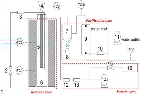
Figure 1.
Process Diagram of Fixed-bed Gasification System. 1. Oxygen supply; 2. Oxygen controller; 3. Mass flow controller; 4. Feeder; 5. Feeding pipe; 6. Reactor with heater; 7. Cyclone; 8. Residue collector; 9. Scrubber‘ 10. Fabric filter; 11. Water pump; 12. Filtering system; 13. Silica gel; 14. Gas vacuum pump; 15. Syngas controller; and 16. Micro-GC, TC Thermocouples.
Table 3.
Experimental Conditions of Gasification at a Fixed-bed Reactor.
Table 4.
The Gas Analysis Methods: The Analytical Conditions of Micro-GC.
2.3. Manufacturing Process of Clay Brick Using the Melting Slag
The residues collected from the ASR gasification process were melted at approximately 1300 °C for 2 h, then the melting slag was slowly air-cooled [32]. The morphology of the melting slag produced at different melting temperatures was observed using scanning electron microscopy (SEM). The melting slag was then crushed using a mill, and its size distribution was analyzed. The resulting aggregate was used as a substitute for kaolin in clay bricks at 1–10 wt.%. These concentration levels were selected because the clay brick mixture results in foam when the melting slag content is greater than 10 wt.%. The clay bricks were manufactured at a firing temperature of approximately 1200 °C for 24 h using the methods employed by a clay-brick manufacturing company in Korea (see Table 5). The absorption and compressive strength of the manufactured clay bricks were measured according to Korean Industrial Standards, and Table 6 summarizes the methods and instruments used in the measurements [33,34,35,36]. Figure 2 illustrates the overall ASR recycling process used in the present study and presents the characteristics of the produced syngas and clay bricks.
Table 5.
Manufacturing Conditions for Clay Bricks.
Table 6.
Test methods and Instrument Specifications.
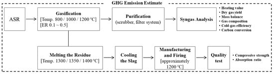
Figure 2.
Process of Present Study for Efficient ASR Disposal.
2.4. Estimation of GHG Emissions in the ASR Melting Gasification Process
Guidelines and equations provided by the Korean Ministry of Environment can be used to estimate GHG emissions from various recycling facilities, including landfills, incinerators, and co-generation plants [37]. In the present study, the carbon dioxide, methane, and nitrous oxide emissions from the proposed ASR melting gasification process were compared with those from the simulation of ASR incineration. The simulation used the GHG equations and assumed that the ASR was only combusted in a reactor. For the ASR melting gasification process, data from the gasification experiment, such as the yield of carbon dioxide and methane, were used to estimate the GHG emissions. To compare the theoretical and experimental GHG emissions, the temperature and equivalence ratio (ER) were set to approximately 1000 °C and 0.5. In addition, nitrous oxide emissions were ignored during the gasification process because they were considered significantly low. Figure 3 summarizes the assumptions and equations used to compare the ASR incineration and melting–gasification processes.
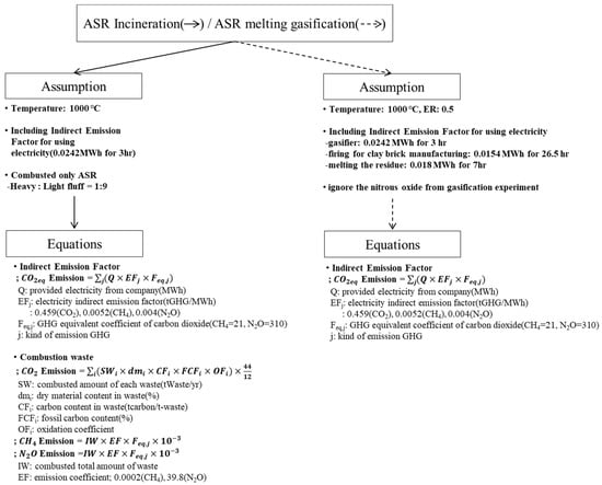
Figure 3.
Concept for GHG Emission Estimate.
3. Results and Discussion
3.1. Thermochemical Characteristics of the ASR
The elemental analysis of the ASR revealed a carbon, hydrogen, oxygen, and nitrogen contents of 52.75, 7.02, 1.78, and 15.81 wt.%, respectively. Sulfur, which can be converted into H2S, was detected at concentrations below 1 wt.%. Furthermore, chlorine, a source of erosion and dioxins, was present at only 1.37 wt.%. The higher heating value (HHV) of the ASR was 21,680 kJ/kg (Table 7).
Table 7.
Results of Elemental Analysis for ASR and Other Wastes.
The results of the elemental analysis revealed that the ASR composition was similar to those of other combustible wastes such as biomass or municipal solid waste, thus making it a suitable solid refused fuel (SRF) or alternative fuel [38,39,40]. To confirm this, the characteristics of the ASR used in the present study were compared with those of other combustible wastes reported in the literature. In addition, the heating value and elemental analysis results of the ASR was compared with those of plastic industrial waste from a company in Korea [41,42]. It was found that sawdust has lower contents of carbon and hydrogen (45.93 and 6.65 wt.%, respectively) than the ASR, whereas the proportion of oxygen in sawdust is significantly higher at 45.96 wt.%. Moreover, the proportion of sulfur in sawdust is low. In addition, the HHV of sawdust is 17,623 kJ/kg, which is approximately 4200 kJ/kg higher than that of the ASR. Based on these results, ASR exhibits strong potential to be used as a fuel. In contrast, plastic, which has a high molecular weight, has significantly higher carbon and hydrogen contents (80.16 and 12.34 wt.%, respectively) than the ASR. However, the nitrogen and oxygen contents in plastic are exceptionally low (0.73 and 0.16 wt.%, respectively). The plastic waste also had the highest chlorine content of the three types of waste (2.76 wt.%).Besides, the SRF demonstrated a similar elemental composition to that of sawdust. More specifically, sulfur was not detected in the SRF, but further analysis is needed to verify the samples, since it is an industrial waste.
Table 8 presents the proximate analysis results for each waste material. The ASR consisted of 1.17 wt.% moisture, 63.90 wt.% volatile compounds, 18.80 wt.% fixed carbon, and 16.13 wt.% ash. Volatile compounds and fixed carbon are particularly important for the gasification process because a higher proportion of combustible compounds results in a higher conversion rate of hydrocarbons into syngas [43,44]. In addition, the lower moisture content in the ASR than sawdust is also beneficial for its use as a fuel in a thermochemical process; additionally, a low moisture content offers higher economic efficiency because a pre-drying process is not required.
Table 8.
Proximate Analysis Result on Each Material.
The TG analysis results determine the characteristics of the feedstock or fuel, such as the temperature of the final reaction; therefore, the results are important for determining experimental conditions [27]. In the present study, a TG plot was generated under reduction conditions in the presence of nitrogen as the temperature increased at a rate of 10 °C/min. A TG analysis was conducted under both reduction and oxidation conditions (with nitrogen and air, respectively), because it was necessary to measure the weight reduction under similar conditions to those in the gasification process.
Figure 4 shows the results of the TG analysis. The ASR, wood, and plastic waste exhibited similar reducing trends, regardless of the presence of oxygen. Unlike the other types of waste, the ASR consisted of various materials, such as synthesis resins, rubber, and plastic. As a result, its thermal reaction was lower than that of wood and plastic waste [28]. The TG plot for the ASR was dominated by the graph of light fluff since light fluff was the major component of the ASR (~80 wt.%). In contrast, heavy fluff had a similar TG graph to that of plastic waste [45]. Based on the ASR TG plot, it can be predicted that the optimal operating temperature for ASR gasification is above 900 °C. The residues were more frequently converted to gasification products such as hydrogen, carbon monoxide, and methane above this temperature. The main purpose of gasification is to produce syngas, such as hydrogen and carbon monoxide, which are produced from hydrocarbons [46]. Thus, the remaining residues should be thermally cracked at temperatures higher than 900 °C.
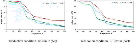
Figure 4.
TGA Results of Fuels.
Unlike wood and plastic, the ASR did not exhibit rapid weight reduction at lower reaction rates because the light fluff in the ASR contains plastic, synthesis resin, and rubber, all of which have polyurethane as a raw material. Compared to other ASR materials, polyurethane requires the highest temperature for thermal reduction. Finally, it can be concluded that the ASR TG results were influenced by the polyurethane content [28]. In addition, based on the combustible residue that remained at a temperature of 950 °C, it was clear that higher temperature, higher pressure and longer residence times were required for the ASR-gasification process.
3.2. Results for ASR Gasification in a Fixed-Bed Reactor
Figure 5 presents the results for syngas production at gasification temperatures of 800, 1000 and 1200 °C. The hydrogen and carbon monoxide levels increased with the increasing temperature and ER, whereas the carbon dioxide levels decreased. The amount of syngas increased with the increasing temperature because the devolatilization reaction occurred first in the thermochemical process for the combustible waste. Thereafter, two main reactions occurred, combustion and the water–gas-shift reactions. In general, gasification reactions cannot be summarized by specific equations because of their complexity; however, the results obtained from the ASR gasification can be explained using the main equations for general gasification. Equations (1), (2) and (5) indicate that the endothermic reactions are facilitated by an increase in the temperature. It was also found that the proportion of carbon monoxide was higher than that of hydrogen with an increase in the ER at the same gasification temperature. Moreover, it was observed that carbon monoxide and hydrogen are predominant, and reactants are more prevalent with the increasing temperature in an exothermic reaction, whereas products are more prevalent with the increasing temperature in an endothermic reaction [47]. Overall, syngas production was not associated with the ER for hydrogen, whereas carbon monoxide exhibited complex reaction pathways that are affected by the temperature and steam ratio.
Water gas C + H2O → CO + H2 +131.5 kJ/mol
Boudouard C + CO2 → 2CO +172 kJ/mol
Water–gas shift CO + H2O → CO2 + H2 −41 kJ/mol
Methanation C + 2H2 → CH4 −74.8 kJ/mol
Steam reforming CH4 + H2O → CO + 3H2 +206 kJ/mol
Oxidation C + O2 → CO2 −406 kJ/mol
C + 0.5O2 → CO −123 kJ/mol
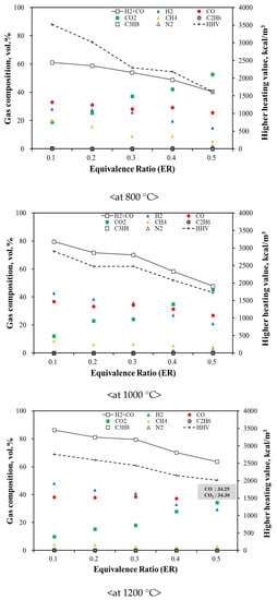
Figure 5.
Gas Composition with Different Temperatures and ER from ASR Gasification.
Unlike carbon monoxide, carbon dioxide production is affected by a change in the ER. This is because higher oxygen levels promote oxidation and facilitate the conversion reaction to carbon dioxide [43]. In contrast, methane production decreased with the increasing temperature, indicating that homogeneous or secondary reactions (CH4 + 2O2 → 2H2O + CO2) were preferred [42].
For each temperature range, the syngas proportion increased with a decrease in the ER, which is advantageous for the ASR gasification. However, the total amount of syngas produced increased with the increasing ER, while the solid residue content decreased. The main goal of gasification is to obtain the highest yield of hydrogen and carbon monoxide, which can be estimated from the dry-gas yield. Therefore, a temperature of 1200 °C and an ER of 0.5 would be the optimum conditions for optimum gas production in ASR gasification. For a gasification power plant, the amount of syngas and solid residue produced is an important factor because increasing the syngas yield and reducing the solid-residue content can improve the power-generation efficiency and ensure continuous operation. The HHV of the produced syngas was estimated, and the results were found to vary with temperature. As a result, the highest HHV of syngas was shown at a temperature of 800 °C (approx. 3500 kcal/kg), since the thermal cracking would be activated at increasing temperatures. The trend observed in the HHV was similar to that of methane, ethane, and propane. The HHV was also affected by changes in the volume of carbon dioxide. It is not economical to transport syngas from its production facility over long distances because it is a low-calorific fuel. However, syngas does have the advantage of being directly usable in the production area as a gas fuel. Figure 5 shows variations in the syngas composition and HHV with increasing ER during the ASR gasification.
During the ASR gasification process, the tar content decreased by less than 10 wt.% with increasing temperature and ER. The conversion rate from high-molecular-weight compounds to low-molecular-weight compounds increased because the compounds cracked to a greater extent at higher temperatures. Additionally, solid residues, including ash, were reduced by 26%. Although combustible ASR compounds did not react completely, a high ASR gasification efficiency can be achieved by controlling oxygen, unlike in incineration (Figure 6). It was also apparent that the dry-gas yield was affected by changes in the temperature and ER; in particular, the dry gas yield increased with the increasing ER and temperature, indicating that the ASR reaction improved under these conditions. Thus, it can be concluded that an increased ER and high temperatures increase the yield of syngas [48,49].
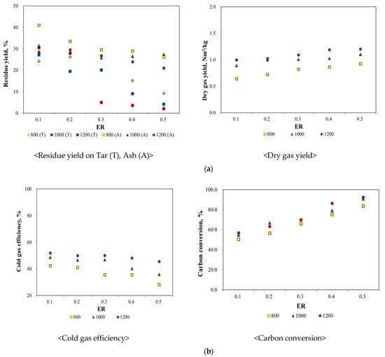
Figure 6.
Assessment of ASR Gasification Efficiency. (a) Yields of Solid Residue and Dry Gas with Different Temperatures and ER, (b) Results of Carbon Conversion and Cold gas Efficiency with Different Temperatures and ER.
The cold-gas efficiency, calculated based on the syngas composition and cold-gas efficiency equation, decreased with an increase in the temperature and ER. The heating value of the syngas decreased because the production of carbon dioxide increased with an increase in the temperature and ER. Carbon conversion and cold gas efficiency, which are used to evaluate the gasification process, can help to measure the carbon converted into in the ASR, because the hydrocarbon gas and the dry-gas yield are used as calculation factors. This carbon conversion was calculated using the equation provided in Table 9. The results in Figure 6 indicate that the carbon conversion increased with the increasing temperature and ER; however, the cold-gas efficiency exhibited an opposite trend. As the temperature and ER increased, the production of carbon dioxide and other hydrocarbon gases increased and decreased, respectively.
Table 9.
Equations of Carbon Conversion and Cold-gas Efficiency.
3.3. Quality Assessment of Clay Brick Manufactured from Melting Slag
The clay brick manufactured using the melting slag was subjected to quality-control testing for compressive strength and absorption, based on the Korean Industrial Standard (Figure 7). The manufactured clay brick exhibited a compressive strength of over 22.54 N/mm2 and an absorption ratio of less than 10%, thus satisfying the Korean Industrial Standard. The clay brick also had a higher compressive strength than the standard clay brick, although this decreased as the melting temperature increased. In addition, as illustrated by the SEM analysis, the porosity of the melting slag increased with higher melting temperatures (Figure 8), indicating that porosity affects the compressive strength of the clay bricks. However, the compressive strength increased at a higher melting slag content, reaching 153.35 N/mm2 with a melting slag content of 10 wt.% and a melting temperature of 1300 °C. Additionally, foaming of the slag was only apparent in the clay brick when more than 10 wt.% of the melting slag was used. Overall, based on the results of the quality control testing, it was concluded that the optimum melting slag content was 10 wt.%. However, it should be noted that all clay bricks, regardless of the melting slag content, met the absorption ratio standard. Moreover, the contents of heavy metals in melting slag have to be measured before applying a commercial plant. According to advanced research, the content of copper was revealed to 34,000 mg/kg in ASR ash [50,51]. In general, the content of heavy metal is regulated by the leaching test in Korea, but slag has been often used to aggregate, for application in embankments, and so on. Therefore, further study is required in future, since the contents of heavy metal could be concentrated in melting slag.
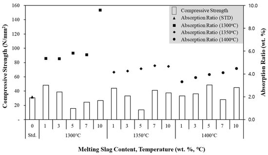
Figure 7.
Compressive Strength Results of Clay Bricks for Different Conditions.
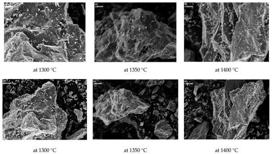
Figure 8.
Pictures of Melting Slag by Scanning Electron Microscopy (the top: 1000/the bottom: 300).
3.4. GHG Emissions from the ASR Melting Gasification Process
The GHG emissions obtained from the proposed ASR gasification process were compared with those obtained from the simulated incineration under the same conditions (Table 10). In order to compare via imperative criteria, we applied a general operation temperature in the incineration process. The GHG levels were found to be affected by the amount of carbon dioxide emissions in both the incineration simulation and ASR gasification. Carbon dioxide accounted for the highest proportion of emissions in both the processes because the carbon dioxide production increased with an increase in the ER, which was set at 0.5. Furthermore, the electricity used to operate the melting and firing furnace was also considered as an indirect emission factor, and it had a significant effect on the overall GHG emissions. However, when the GHG emissions were calculated per ton of waste, the ASR melting–gasification process produced GHG emissions that were approximately ten times higher than those obtained from the ASR incineration. It was revealed that the simulation value of ASR incineration seems to be underestimated, since it does not reflect actual conditions, such as volumetric change induced by the incinerator temperature. On the other hand, the ASR-gasification process seems to be overestimated because of the indirect emission factor for melting and firing furnaces. Thus, the efficiency of the process needs to be verified using actual data for thermochemical processes. In addition, melting gasification must be operated in an integrated facility to secure the economy and environment from thermochemical process.
Table 10.
Results of GHG Emission for ASR Incineration and ASR Gasification. Unit: ton/ton.
4. Conclusions
In the present study, the thermochemical characteristics of ASR were analyzed to evaluate their applicability for use in the gasification and melting processes. Various tests under different operating conditions were conducted, and the characteristics of the resulting syngas were assessed. Furthermore, quality control testing was performed on clay bricks manufactured using melting slag. Finally, the GHG emissions produced by the overall process were estimated.
- 1.
- The elemental analysis revealed that the ASR was composed of 52.75 wt.% carbon, 7.02 wt.% hydrogen, 15.81 wt.% nitrogen and 1.78 wt.% oxygen, while the proximate analysis indicated that the ASR contained 1.17 wt.% moisture, 63.90 wt.% volatile compounds, 16.13 wt.% ash, and 18.80 wt.% fixed carbon. Moreover, the ASR is more efficient as an alternative fuel compared to other combustible wastes, since it has higher levels of combustible compounds and a lower moisture content.
- 2.
- In the ASR gasification process, the tar and ash contents decreased by approximately 10 wt.% with increasing temperature and ER. Additionally, the cold-gas efficiency levels and HHV also decreased with an increase in the ER. In particular, the HHV of the gas produced at a lower ER and temperature was higher than that of the gas produced at a higher ER and temperature because there was less oxidation and thermal cracking at a lower ER and temperature. However, the dry gas yield increased from 0.64 Nm3/kg to 1.20 Nm3/kg when the temperature increased from 800 °C to 1200 °C and the ER increased from 0.1 to 0.5, with the carbon conversion exhibiting the same trend. Consequently, considering economy and efficiency, the optimum conditions for the ASR gasification were determined to be a temperature of 1200 °C and an ER of 0.5.
- 3.
- From the results of melting process, the highest compressive strength was shown to be 153.35 N/mm2 when the melting slag content is 10 wt.% at a melting temperature of 1300 °C. According to the results, it was concluded that the optimum melting slag content is 10 wt.% and the optimal melting temperature is 1300 °C. However, the leaching test has to be performed before fixing the melting slag content. In some application cases, the amount of heavy metals could be measured since the manufactured clay brick exhibited foaming, causing a reduction in the compressive strength.
- 4.
- The ASR-gasification process has been proven to be a low GHG emission technology with high energy efficiency. Additionally, even though the ASR residues were melted and fired for clay-brick manufacturing, the GHG emissions remained approximately ten times higher than those produced in the ASR incineration process. It reveals that the purity of carbon dioxide in the flue-gas from the gasification plant was higher than that of the incineration plant. In terms of the operation cost of the carbon capture process for GHG reduction, the gasification plant would be more efficient than an incineration plant. In addition, to identify this process as an eco-friendly technology, a further analysis of the emission levels of dioxins and leaching tests for chlorine and heavy metals are required.
Author Contributions
Conceptualization—H.-M.Y.; Investigation—H.-M.Y., S.-Y.L. and S.-J.C.; Methodology—H.-M.Y.; Resources—Y.-C.S. and H.-N.J.; Supervision—Y.-C.S. and H.-N.J.; Writing: original draft—H.-M.Y.; Writing: review and editing—H.-M.Y., S.-Y.L., S.-J.C., Y.-C.S. and H.-N.J. All authors have read and agreed to the published version of the manuscript.
Funding
This work was supported by a grant from the National Institute of Environmental Research (NIER), funded by the Ministry of Environment (MOE) of the Republic of Korea (NIER-2021-01-01-003) and the Korea Institute of Energy Technology Evaluation and Planning (KETEP) (No. 20184030202240).
Informed Consent Statement
Not applicable.
Data Availability Statement
Not applicable.
Conflicts of Interest
The authors declare no conflict of interest.
References
- Korea Energy Management Corporation. New & Renewable Energy RD&D Strategy 2030—Waste Part, 1–14. 2007. Available online: https://www.energy.or.kr/web/kem_home_new/info/data/open/kem_view.asp?q=13726 (accessed on 7 January 2008).
- Geyer, R.; Jampeck, J.; Law, K. Production, use, and fate of all plastics ever made. Sci. Adv. 2017, 3, 1–5. [Google Scholar] [CrossRef] [PubMed]
- Euromap. Plastic Resin Production and Consumption in 63 Countries Worldwide. 2016. Available online: https://www.pagder.org/images/files/euromappreview.pdf (accessed on 8 December 2016).
- Lee, K.B. Studies on Solidification and Melting Characteristics for Developing Energy Recovery System of Automobile Shredder Residue. Master’s Thesis, Yonsei University, Seoul, Korea, 2012. [Google Scholar]
- Cossu, R.; Lai, T. Automotive shredder residue (ASR) management: An overview. Waste Manag. 2015, 45, 143–151. [Google Scholar] [CrossRef] [PubMed]
- Vermeulen, I.; Van Caneghem, J.; Block, C.; Baeyens, J.; Vandecasteele, C. Automotive shredder residue (ASR): Reviewing its production from end-of-life vehicles (ELVs) and its recycling, energy or chemical’s valorisation. J. Hazard. Mater. 2011, 190, 8–27. [Google Scholar] [CrossRef] [PubMed]
- European Parliament and Council. Directive 2000/53/EC of the European Parliament and of the Council of 18 September 2000 on End-of Life Vehicles. Available online: https://eur-lex.europa.eu/resource.html?uri=cellar:02fa83cf-bf28-4afc-8f9f-eb201bd61813.0005.02/DOC_1&format=PDF (accessed on 29 May 2020).
- Cullis, C.F.; Hirschler, M.M. The Combustion of Organic Polymers, 5; Oxford University Press: Jericho, NY, USA, 1981. [Google Scholar]
- Mirabile, D.; Pistelli, M.I.; Marchesini, M.; Falciani, R.; Chiappelli, L. Thermal valorization of automotive shredder residue: Injection in blast furnace. Waste Manag. 2002, 22, 841–851. [Google Scholar] [CrossRef]
- Day, M.; Shen, Z.; Cooney, J.D. Pyrolysis of automotive shredder residue: An analysis of the products of a commercial screw kiln process. J. Anal. Appl. Pyrol. 1996, 37, 49–67. [Google Scholar] [CrossRef][Green Version]
- Day, M.; Shen, Z.; Cooney, J.D. Pyrolysis of auto shredder residue: Experiments with a laboratory screw kiln reactor. J. Anal. Appl. Pyrol. 1999, 51, 181–200. [Google Scholar] [CrossRef]
- Donaj, P.; Kaminsky, W. Recycling of polyolefins by pyrolysis in a fluidized bed reactor. In Proceedings of the 17th European Biomass Conference, Hamburg, Germany, 29 June–3 July 2009. paper No.OB4.4. [Google Scholar]
- Forsgren, C. Microwave pyrolysis a new recycling tool. In Proceedings of the 26th Annual International Conference on Incineration and Thermal Treatment Technologies, Phoenix, AZ, USA, 14–18 May 2007. [Google Scholar]
- Galvagno, S.; Fortuna, F.; Cornacchia, G.; Casu, S.; Coppola, T.; Sharma, V.K. Pyrolysis process for treatment of automotive shredder residue: Preliminary experimental results. Energy Convers. Manag. 2001, 42, 573–586. [Google Scholar] [CrossRef]
- Harder, M.K.; Forton, O.T. A critical review of developments in the pyrolysis of automotive shredder residue. J. Anal. Appl. Pyrol. 2007, 79, 387–394. [Google Scholar] [CrossRef]
- Joung, H.T.; Kim, K.H.; Seo, Y.C. Effects of oxygen, catalyst and PVC on the formation of PCDDs, PCDFs and dioxin-like PCbs in pyrolysis products of automotive residues. Chemosphere 2006, 65, 1481–1489. [Google Scholar] [CrossRef]
- Kondoh, M.; Hamai, M.; Yamaguchi, M.; Mori, S. Study of gasification characteristics of automobile shredder residue. JSAE Rev. 2001, 2, 234–236. [Google Scholar] [CrossRef]
- Kurose, K.; Okuda, T.; Nishijima, W.; Okada, M. Heavy metals removal from automotive shredder residues (ASR). J. Hazard. Mater. 2006, 137, 1618–1623. [Google Scholar] [CrossRef] [PubMed]
- Marco, I.; Caballero, B.M.; Cabrero, M.A.; Laresgoiti, M.F.; Torres, A.; Chomon, M.J. Recycling of automotive shredder residues by means of pyrolysis. J. Anal. Appl. Pyrol. 2007, 79, 403–408. [Google Scholar] [CrossRef]
- Srogi, K. An overview of current processes for the thermochemical treatment of automobile shredder residue. Clean Technol. Environ. Policy 2008, 10, 235–244. [Google Scholar] [CrossRef]
- Selvarajoo, A. Slow pyrolysis of Durio zibethinus rind and the influence of carbonization temperature on biochar properties. Mater. Sci. Eng. 2021, 1092, 012042. [Google Scholar] [CrossRef]
- Donaj, P.; Kubik, K.; Swiderski, A.; Yang, W.; Blasiak, W.; Forsgren, C. Assessment of ASR treatment using pyrolysis and reforming of its residences for small scale electricity generation systems. In Proceedings of the 27th Annual International Conference on Thermal Treatment Technologies, Montreal, QC, Canada, 12–16 May 2008. [Google Scholar]
- Kantarelis, E.; Donaj, P.; Yang, W.; Zabaniotou, A. Sustainable valorization of plastic wastes for energy with environmental safety via high-temperature pyrolysis (HTP) and high-temperature steam gasification (HTSG). J. Hazard. Mater. 2009, 167, 675–684. [Google Scholar] [CrossRef]
- Kubik, K. Reforming of Car Residues Pyrolysis Products into High-Purity Synthetic Gas for Small-Scale Electricity Generation. Master’s Thesis, Royal Institute of Technology, Stockholm, Sweden, 2008. [Google Scholar]
- Malkow, T. Novel and innovative pyrolysis and gasification technologies for energy efficient and environmentally sound MSW disposal. Waste Manag. 2004, 24, 53–79. [Google Scholar] [CrossRef]
- Molino, A.; Chianese, S.; Musmarra, D. Biomass gasification technology: The state of the art overview. J. Energy Chem. 2016, 25, 10–25. [Google Scholar] [CrossRef]
- Hwang, H. Gasification of Wood Pellet Using Multi-Stage Reactor System. Master’s Dissertation, Seoul National University of Science and Technology, Seoul, Korea, 2011; pp. 36–44. [Google Scholar]
- Jung, H.T. Study on the Pyrolysis Characteristics of Automobile Shredder Residue. Master’s Thesis, Yonsei University, Seoul, Korea, 2003. [Google Scholar]
- Donaj, P.; Yang, W.; Błasiak, W.; Forsgren, C. Recycling of automobile shredder residue with a microwave pyrolysis combined with high temperature steam gasification. J. Hazard. Mater. 2010, 182, 80–89. [Google Scholar] [CrossRef]
- Kim, K.H.; Joung, H.T.; Nam, H.; Seo, Y.C.; Hong, J.H.; Yoo, T.W.; Lim, B.S.; Park, J.H. Management status of end-of-life vehicles and characteristics of automobile shredder residues on Korea. Waste Manag. 2004, 24, 533–540. [Google Scholar] [CrossRef]
- Endoh, S.; Takahashi, K.; Lee, J.R.; Ohya, H. Mechanical treatment of automobile shredder residue for its application as a fuel. J. Mater. Cycles Waste Manag. 2006, 8, 88–94. [Google Scholar] [CrossRef]
- Yang, W.S.; Cho, S.J.; Lee, K.B.; Seo, Y.C.; Kim, W.H. Studies on physicochemical and melting characteristics of automobile shredder residue for enhancing end of life vehicles (ELVs) recycling rate. In Proceedings of the Annual Conference of Japan Society of Material Cycles and Waste Management, Sendai, Japan, 22–24 October 2012. Japan Society of Material Cycles and Waste Management. [Google Scholar]
- Korean Standards Association. Concrete Interlocking Block for Side Walk and Road. KS F, 4419. 2009. Available online: https://e-ks.kr/streamdocs/view/sd;streamdocsId=72059225013305044 (accessed on 13 November 2017).
- Korean Standards Association. Clay Brick. KS L, 4201. 2012. Available online: https://e-ks.kr/streamdocs/view/sd;streamdocsId=72059203168086519 (accessed on 7 July 2015).
- Korean Standards Association. Concrete Curbs. KS F, 4006. 2013. Available online: https://e-ks.kr/streamdocs/view/sd;streamdocsId=72059207383841907 (accessed on 7 July 2015).
- Korean Standards Association. Preast Concrete Paving Flags. KS F, 4001. 2015. Available online: https://e-ks.kr/streamdocs/view/sd;streamdocsId=72059225017138675 (accessed on 7 July 2015).
- Ministry of the Environment. The Manual for Estimating a GHG Emission Amount -Waste Part, 70–301. 2012. Available online: https://www.keco.or.kr/kr/business/climate/communityid/187/view.do?p=1&idx=328&f=1&q= (accessed on 4 December 2012).
- Kim, S.W.; Koo, B.S.; Ryu, J.W.; Lee, J.S.; Kim, C.J.; Lee, D.H.; Kim, G.R.; Choi, S. Bio-oil from the pyrolysis of palm and Jatropha wastes in a fluidized bed. Fuel Processing Technol. 2013, 108, 118–124. [Google Scholar] [CrossRef]
- Sulaiman, F.; Abdullah, N. Optimum conditions for maximizing pyrolysis liquids of oil palm empty fruit bunches. Energy 2011, 36, 2352–2359. [Google Scholar] [CrossRef]
- Cho, S.J. Studies on Gasification and Melting Characteristics of Waste and Biomass. Ph.D. Dissertation, Yonsei University, Seoul, Korea, 2012. [Google Scholar]
- Yoo, H.M.; Chung, T.H.; Lee, S.Y.; Park, S.W.; Seo, Y.C. A study on applicability for air pollutant materials sources: Characteristics comparison of carbon dioxide isotope with conbustion engines. J. Korea Soc. Waste Manag. 2019, 36, 644–651. [Google Scholar] [CrossRef]
- Cuiping, L.; Chuangzhi, W.; Yanyongjie, H.H.; Haitao, H. Chemical elemental characteristics of biomass fuels in China. Biomass Bioenergy 2004, 27, 119–130. [Google Scholar] [CrossRef]
- Kim, J.S.; Park, Y.K.; Kang, B.S.; Park, H.J.; Lee, K.H.; Kim, E.Y.; Kim, S.D.; Song, D.K.; Kim, Y.C. Production of Clean Bio-Fuel from Rice Straw by Flash Pyrolysis and Catalytic Upgrading; The University of Seoul: Seoul, Korea, 2005. [Google Scholar]
- Lee, J.G.; Kim, J.H.; Lee, S.H.; Choi, Y.C.; Kim, Y.G.; Yoo, K.S.; Lee, S.H. Development of fluidized bed reactor for the pyrolysis and gasification of agricultural and forestry wastes. Korea Inst. Energy Res. 2005, 19–73. [Google Scholar]
- Iliuta, I.; Leclerc, A.; Larachi, F. Allothermal steam gasification of biomass in cyclic multi-compartment bubbling fluidized-bed gasifier/combustor–New reactor concept. Bioresour. Technol. 2010, 101, 3194–3208. [Google Scholar] [CrossRef]
- Bridgwater, A.V. Review of fast pyrolysis of biomass and product upgrading. Biomass Bioenergy 2012, 38, 68–94. [Google Scholar] [CrossRef]
- Park, J.K.; Seo, Y.C.; Lee, J.S.; Yoo, H.M.; Yang, W.S.; Park, S.W.; Han, B.H.; Choi, H.S.; Cho, S.J.; Lee, K.B.; et al. Studies on physicochemical characteristics and optimal melting condition of automobile shredder residue in a melting furnace. J. Korea Soc.Waste Manag. 2013, 30, 189–198. [Google Scholar] [CrossRef]
- Shen, L.; Gao, Y.; Xiao, J. Simulation of hydrogen production from biomass gasification in interconnected fluidized beds. Biomass Bioenergy 2008, 32, 120–127. [Google Scholar] [CrossRef]
- Kim, M.J.; Ryu, H.L.; Lee, W.K. Coal gasification in a fluidized bed at atmospheric pressure. J. Korean Inst. Chem. Eng. 1983, 21, 20–27. [Google Scholar]
- Kaewluan, S.; Pipatmanomai, S. Gasification of high moisture rubber woodchip with rubber waste in a bubbling fluidized bed. Fuel Process. Technol. 2011, 92, 671–677. [Google Scholar] [CrossRef]
- Lee, H.Y. Characteristics and heavy metal leaching of ash generated from incineration of automobile shredder residue. J. Hazard. Mater. 2007, 147, 570–575. [Google Scholar] [CrossRef] [PubMed]

Publisher’s Note: MDPI stays neutral with regard to jurisdictional claims in published maps and institutional affiliations. |
© 2022 by the authors. Licensee MDPI, Basel, Switzerland. This article is an open access article distributed under the terms and conditions of the Creative Commons Attribution (CC BY) license (https://creativecommons.org/licenses/by/4.0/).