Article

Fast Real-Time RDFT- and GDFT-Based Direct Fault Diagnosis of Induction Motor Drive

by
Piotr Kołodziejek
* and
Daniel Wachowiak
Department of Electrical and Control Engineering, Gdansk University of Technology, 80-398 Gdansk, Poland
*
Author to whom correspondence should be addressed.
Energies 2022, 15(3), 1244; https://doi.org/10.3390/en15031244
Submission received: 8 November 2021 / Revised: 27 January 2022 / Accepted: 3 February 2022 / Published: 8 February 2022

Abstract

:
This paper presents the theoretical analysis and experimental verification of a direct fault harmonic identification approach in a converter-fed electric drive for automated diagnosis purposes. On the basis of the analytical model of the proposed real-time direct fault diagnosis, the fault-related harmonic component is calculated using recursive DFT (RDFT) and Goertzel DFT (GDFT), applied instead of the full spectrum calculations required in the most popular FFT algorithm. The simulation model of an inverter sensorlessly controlled induction motor drive is linked with the induction machine rotor fault model for testing the sensitivity of the GDFT- and RDFT-based fault diagnosis to state variable estimation errors. According to the presented simulation results, the accuracy of the direct identification of a fault-related harmonic is sensitive to the quality of fault harmonic frequency estimation. The sensitivity analysis with respect to RDFT and GDFT algorithms is included. Based on the experimental setup with a sensorlessly controlled induction motor drive with the investigated rotor fault, fault diagnosis algorithms were implemented in the microprocessor by integration with the control system in one microcontroller and experimentally verified. The RDFT and GDFT approach has shown accurate and fast direct automated fault identification at a significantly decreased number of arithmetical operations in the microcontroller, which is convenient for the frequency-domain fault diagnosis in electric drives and supports fault-tolerant control system implementation.

1. Introduction

Increasing requirements are formulated for converter-fed variable-speed drives with respect to their control quality, reliability and safety. These requirements are intended to provide safe and reliable machine operation, including early fault detection and fault-tolerant control to avoid critical faults and their consequences. In electrical machines, the most convenient diagnosis methods in industrial applications are based on the frequency domain analysis utilizing known analytical models of faults and their frequency dependencies [1,2,3,4,5,6,7,8,9,10,11,12]. Due to measurement simplicity, the most popular method in recent years for diagnosing induction motor drives was the Motor Current Signature Analysis (MCSA), with reasoning based on the harmonic analysis using the Fast Fourier Transform (FFT) [1,2,3,4,5]. The induction motor diagnosis usually requires external current measurements and human expert knowledge. According to the cited articles, the MCSA approach is convenient for diagnosing stator and rotor faults, as well as eccentricity and bearing damages. The fault diagnosis in the frequency domain is usually based on a known mathematical model applied for specified harmonic frequencies of the fault-related symptom and their amplitude identification and analysis [13,14,15,16,17,18,19]. The bearing fault is the most common in induction machines. However, rotor faults are also among the top three faults most often recorded in induction motors [10,11,13]. Statistically, a stator fault is more probable [5]. Moreover, the rotor fault occurrence probability is different for low- and high-power induction machines due to different manufacturing technology, i.e., cast alloy cage or soldered copper cage. The nominal power of the induction motor is related to the specified size of the rotor and its temperature gradient during operation, hence its vulnerability to the rotor fault is also different [11]. A great deal of scientific interest has been focused on the rotor faults of induction motors [6,8,10,11,12,13,14,15,16,17,18,19,20]. The computing speed of current microcontrollers makes it possible to integrate the control, monitoring and automated diagnosis system in one microprocessor, which can be further developed to the fault ride-through and fault-tolerant control systems. When a rotor fault of the induction motor is slowly emerging, its compensation or even elimination of its impact is possible by proper fault-tolerant control application; therefore, the exact detection, identification and extraction of the fault is required [21]. Reported methods for the IM diagnosis are focused on early-stage detection and fault range accuracy identification. Some diagnosis methods require a determined operational state of the machine. For transient state operation diagnosis, the wavelet method is proposed in [20] and based on stray flux observation in [21]. The automated detection method for the rotor fault diagnosis is reported in [6], but it is dedicated only to the standstill operation condition. In Methodology, the diagnosis is based on a registering signal, e.g., motor current, offline or online frequency domain analysis by calculation all harmonics in the spectra up to the Nyquist frequency, which is necessary in FFT due to the butterfly algorithm principle [2,3,9,22,23,24,25]. The proposed diagnosis methodology is based on direct fault-related harmonic calculation using GDFT and RDFT, therefore, calculations are limited to the amplitude determination of the fault-related harmonics, significantly increasing diagnosis time by decreasing the number of arithmetical operations. Motor slip is estimated using the speed observer implemented for the sensorless operation of the drive. The proposed approach is beneficial, assuming an online diagnosis in the microprocessor with the implemented control system of the IM drive. In [9], a sliding window DFT is proposed for online rotor fault diagnosis; however, in this report, the calculation of the slip is based on the sidelobes leakage phenomenon observed from rotor slot harmonics, and issues of amplitude errors compared to the FFT analysis and slip estimation error are not addressed. In comparison to the method reported in [9], the proposed method does not require identification of the number of rotor bars and the number of pairs of poles. Moreover, the proposed method is verified in the vector control system. The vector control system in the fault diagnosis, which affects the amplitudes of the identified fault symptoms, is assumed in a few reports [13,21,22,26]. The inverter-fed electric drive control system often uses FPGA and a microprocessor, along with the supply voltage vector generation method, for ADC/DAC converter handling, state variable estimation and control system variable calculation. Increasing the MIPS (Million Instructions per Second) of microprocessors increases the number of available instructions for the microprocessor in a specified time between interrupts for ADC converter handling, which creates new possibilities for real-time automated diagnostic algorithm applications. The available time Tdiag for of the diagnosis, see Figure 1, depends on the processing time or the control system algorithms and the assumed time between ADC interruptions Tdiag = TADC − TCS, where Tdiag is the time between ADC handling interrupts for diagnosis purposes, TADC is the program execution period between interrupts for ADC handling and TCS is the time of the control system variable calculation.
Considering the high computational load of the control unit in modern electrical drives, the integrated real-time diagnostic methods need to be optimized due to the increasing switching frequency of inverter transistors in many applications, e.g., in SIC MOSFET transistors, which implies decreased TADC, and the feasibility of additional diagnosis algorithms [27]. Moreover, a simultaneous real-time diagnosis implementation for different faults with additional functionalities, as shown in Figure 1, requires optimized and efficient diagnostic algorithms. The application of Fast Fourier Transform is not efficient in this case because it requires computing the full spectra of the harmonics, which is unnecessary assuming that the mathematical equations for specified fault-related symptom harmonics are known. The analysis of the mathematical description of the most common types of faults in an induction machine shows that the fault diagnosis is the identification problem of a single harmonic or a group of harmonics [13]. In this case, the application of algorithms calculating all harmonics in the spectrum, as in the Fast Fourier Transform, is not efficient in the context of the information needed for diagnostic reasoning. The idea of the work presented in this article is to find, implement and verify efficient real-time fault diagnosis methods for modern electric drives, with a variable-speed induction motor drive used as an example. The real-time and automated fault diagnosis is assumed to be implemented in the microprocessor. The diagnostic system is assumed to be integrated with the control system as an extension of the control system program. The rotor fault diagnosis in the voltage-source-inverter (VSI) fed induction motor drive has been selected for the presentation and experimental verification of the proposed methods in a real-time operation regime. The aim of the proposed direct real-time diagnosis is to obtain fast and reliable fault diagnosis by significantly decreasing the computation time, which is related to the number of necessary operations in the microprocessor. The advantages of the proposed methodology are especially significant in the applied complex multi-fault diagnosis system, e.g., in wind turbines, micro smart-grids or electric vehicles [20,28,29,30]. According to the proposed direct calculation of the fault harmonic amplitude, it is assumed that the mathematical description of the fault is known and adequate to the state-of-the-art in the field of electric machine fault modeling. The proposed fault diagnosis is based on identification by estimating the fault-related harmonics in the control system. Inaccurate fault harmonic frequency identification leads to an unreliable diagnosis, and therefore the sensitivity analysis of fault harmonic estimation uncertainty is needed. The authors propose an approach consisting of the application of GDFT and RDFT for fault diagnosis in the direct real-time tracking of one or more fault-related harmonics, instead of registering data for calculating all harmonics in spectra up to the Nyquist frequency as in the FFT-based analyses. Moreover, a sensitivity analysis for rotor fault diagnosis is presented considering rotor speed and slip estimation errors.

2. Asymmetric Induction Machine Modelling
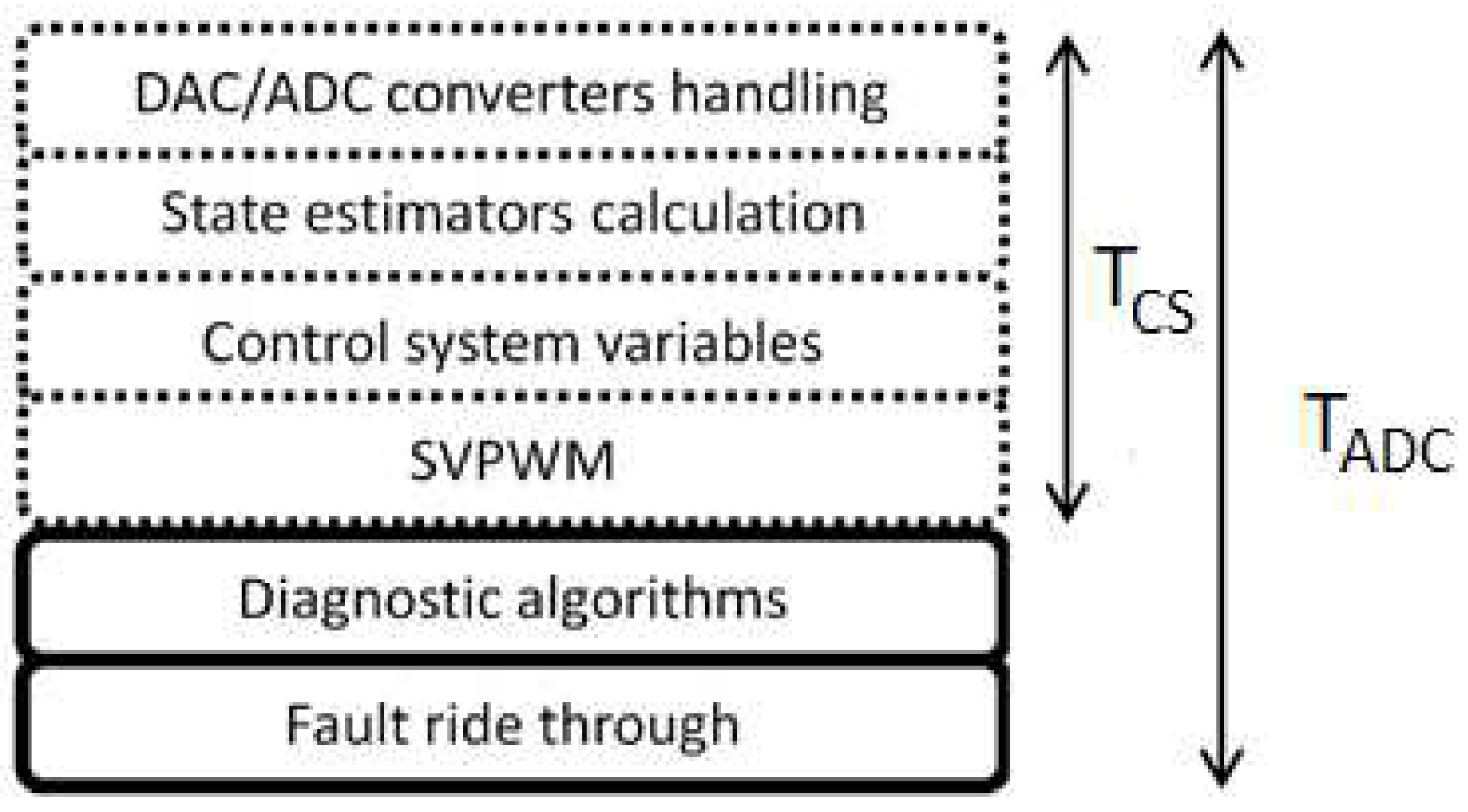
Faults of induction motors can be divided into those originating from electromagnetic or mechanical sources. According to statistical reports, bearing, stator winding and rotor faults occur most often in induction machines. The probability of a rotor fault depends on the nominal power and rotor construction. For high-power induction motors with soldered rotor bars, the probability of rotor fault occurrence is higher compared to low-power machines with cast squirrel-cage rotors due to the higher temperature gradient between the end rings and the rotor bars in the rotor. Considering the broken rotor fault (e.g., broken rotor bars or end rings) in a squirrel-cage induction motor drive, the harmonics observed in the phase stator current are identified at the following frequencies [9,13,21,29]:
f b = ( 1 ± 2 k s ) f 0
where fb is the frequency of the rotor fault harmonic, f0 is the supply stator voltage frequency, s is the motor slip and k is the damped fault harmonic multiplications related to the reflection induced by stator-rotor magnetic coupling.
The left sideband harmonic (LSH) at frequency (1 − 2ks)f0 is related to the rotor fault, while the right sideband harmonic (HSH) at higher frequency (1 + 2ks)f0 is related to the rotor speed oscillations induced by the rotor fault [9,13]. The modeling methodology assuming a 3-phase circuit representation is reported in [19]. An automated diagnosis requires the exact identification of rotor fault frequency. According to (1), the expected rotor fault symptoms emerge as harmonics in the Fourier transform spectrum. For qualitative and quantitative analysis, a detailed mathematical model of an asymmetrical 3-phase squirrel cage induction motor is considered. For simulation analysis, simplifying the assumptions needs to be considered, including the symmetrical air gap and the machine operation at the linear part of the magnetizing current. A multiphase representation of the rotor equivalent circuit is needed for rotor internal asymmetry modeling, i.e., rotor bar or end ring fault, where the number of phases depends on the number of rotor bars.
In the presented asynchronous machine, the mathematical representation of the broken rotor is modeled by increasing the rotor bar resistance. The presented detailed model provides accurate results and is dedicated to modeling cast-cage or slip-ring asynchronous machines. It allows for the direct setting of the parameters of the equivalent circuit model parameters. The simulation of the operation of an induction machine operation with a modeled broken rotor and including a sensorless control system is reported in [31] for a Tamel SG132-S4 induction motor with 28 bars.

3. Control System

The assumed control system for the variable speed induction motor drive is based on the multiscalar control. An advantage of the multiscalar control versus Field-Oriented Control (FOC)is related to the fact that the representation of the variables is independent of the adopted reference frame in the mathematical model, as reported in [32].
In the experimental application of the closed-loop control system, the synthesis flux vector needs to be estimated. Therefore, all state variables in the feedback calculated on the basis of estimated flux are also marked as estimated values
For rotor flux estimation and optional rotor speed estimation, a state observer is applied [33,34]. Therefore, all variables calculated using the estimated flux are also marked as estimated variables. For variable estimation, a speed observer model is applied. The quality of state variable estimation in the state observer depends on the adopted model of the object. In Section 2, the model of the induction machine was considered, where the currents in the stator windings and those currents in individual rotor bars are state variables. This leads to a complex system of differential equations, the number of which depends on the number of rotor bars. The state observer designed for this model would need to estimate all unmeasured state variables, i.e., currents in all rotor bars, which is inconvenient. To describe the dynamics of the object for the observer’s needs, the induction machine model with the stator current vector and the rotor flux vector assumed as state variables is sufficient. The state observer synthesis based on the extended model for an induction machine as reported in [32,33,34] is performed by applying the following mathematical representation [33]:
d i ^ s d τ = a 1 i ^ s + a 2 ψ ^ r + j a 3 ζ ^ + a 4 u s + k 11 ζ ˜ + j k 12 ζ ˜ + k 13 i ˜ s + j k 14 i ˜ s
d ψ ^ r d τ = a 5 i ^ s + a 6 ψ ^ r + j ζ ^ + k 21 ζ ˜ + j k 22 ζ ˜ + k 23 i ˜ s + j k 24 i ˜ s
where ^ means the estimated values, k11k34 are the gain values of the speed observer and i ˜ s , ζ ˜ are the stator current and EMF estimation error vectors, respectively, defined as:
i ˜ s = i s i ^ s
ζ ˜ = ω ^ r ψ ^ r ζ ^
The estimated rotor speed is then determined as:
ω ^ r = ψ ^ r α ζ ^ α + ψ ^ r β ζ ^ β ψ ^ r 2
where ψ ^ r α , ψ ^ r β are the estimated orthogonal components of the rotor flux vector, ψ ^ r is the estimated rotor flux module and ζ ^ α , ζ ^ β are the estimated orthogonal components of the EMF vector.
For 12 gain values k11k34 of the state observer, evolutionary optimization algorithms are applied to provide stability of speed observer operation by properly placing the eigenvalues according to the control system theory. The application of a genetic algorithm for searching an optimized set of parameters is reported in [33,34]. An extended analysis of the sensorless control system based on the proposed modeling approach is reported in [13,21,29].

4. Direct DFT-Based Fault Diagnosis Approach

Considering the fault diagnosis approach in frequency domain, a discrete Fourier transformation is applied to the registered stator current signal to convert a given sample sequence window into a sequence of harmonics [34]:
X k = n = 0 N 1 x n e i 2 π N k n = n = 0 N 1 x n [ cos ( 2 π k n / N ) i sin ( 2 π k n / N ) ] ,
where xn is the sequence of registered samples, and k/N is the frequency of the sinusoidal wave-k cycles per N samples. DFT is usually calculated using the butterfly algorithm for the Fast Fourier Transform invented by Cooley and Tukey [34], which provides the increased efficiency of calculations by decreasing the computational complexity from O(N2) to O(Nlog(N)). Most faults in AC machines can be identified on the basis of one or a group of fault-related harmonics, thus it is more efficient to perform a diagnosis using algorithms providing direct calculation of the fault harmonic, unless all harmonics in the spectrum are needed. Efficient fault diagnosis algorithms are highly desired considering a limited time between microprocessor interrupts, as presented in Figure 1, and the high computational complexity resulting from the need to calculate state variable estimators required for both sensor-based and sensorless control system topologies. The rotor fault diagnosis of the induction motor can be identified by analyzing a selected state variable, e.g., phase stator current, Park’s vector modulus of the stator current, estimated rotor flux, electromagnetic torque or rotor speed during the steady-state operation of the machine [21,29]. The calculation of all harmonics in the spectrum using the FFT algorithm increases the number of arithmetical operations, which, consequently, increases the overall time of calculations and involves more memory resources in the microprocessor. Considering a known fault-related harmonic frequency (2), the amplitude of the harmonic at the fault frequency is directly calculated from the current stator phase measurement results using the recursive algorithm:
A k = n = 0 N 1 a n w N k n ,
where: N—number of samples, n—sample number, an—value of the n-th sample and w N = e i 2 π N .
The output values of the DFT are updated using the recursive algorithm as follows:
X k ( n ) = X k ( n 1 ) + ( x ( n ) x ( n N ) ) w N k n
As a result of the application of the recursive direct Fourier transform, the amplitudes of the fault-related harmonic are updated every sample of the acquired signal in the sliding window. A significant drawback of this approach is the cumulation of numerical errors related to the finite precision of numerical data representation in the microcontroller. Different approaches to compensate for this drawback can be named. Resetting the diagnostic algorithm can be performed without disturbing its operation. According to the assumption of continuous operation of the diagnostic algorithm, the recursive DFT algorithm is periodically reset to reduce the cumulation of numerical errors. The application of the recursive algorithm for DFT calculation decreases the number of arithmetical operations from 2N multiplication and adding operations to four adding and two multiplication operations for a single harmonic amplitude calculation. The computational complexity is decreased from O(N) to O(1). Another considered approach for direct amplitude calculation of a single harmonic is the Goertzel algorithm, which is known from application in the dual-tone multi-frequency (DTMF) tone detection in telecommunication and in magnetic coupling simulation [35]. According to the Goerzel algorithm, the DFT amplitude of a single harmonic is obtained as follows [35]:
u k ( n ) = x ( n ) + 2 cos ( 2 π k N ) u k ( n 1 ) u k ( n 2 )
y ( n ) = u k ( n ) w N k u k ( n 1 )
The application of the Goertzel algorithm decreases the computational complexity because sample Equation (10) are only calculated, while Equation (11) is determined at the end of full window acquisition. In Equation (10), the term: 2 cos(2πk/N) has a fixed value, unlike the recursive DFT algorithm where the trigonometric functions converting wN−kn to real and imaginary values in Equation (9) require the information about the sample number. It is possible to overcome this problem in the recursive DFT algorithm via the tabularization of trigonometric values from 1 to N, however, it requires the allocation of additional memory resources in the microprocessor.

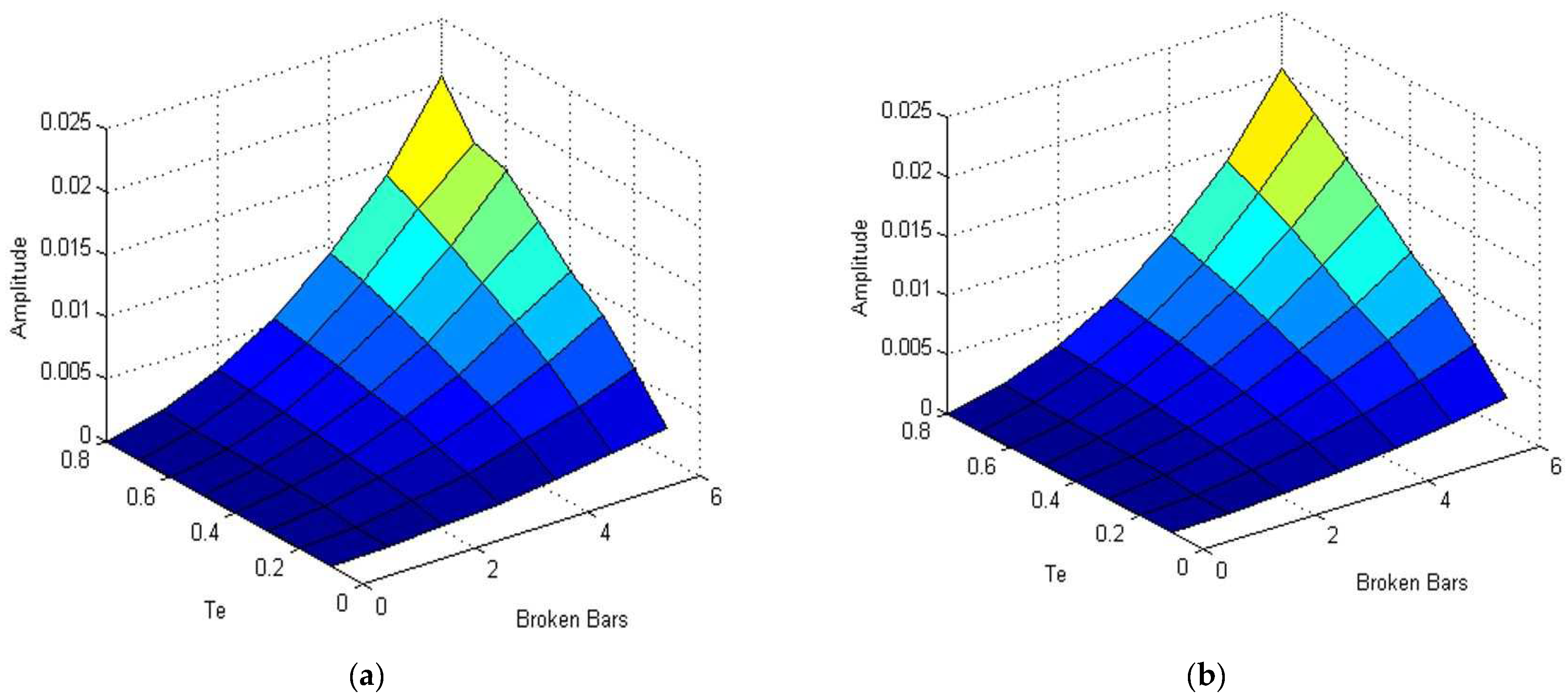
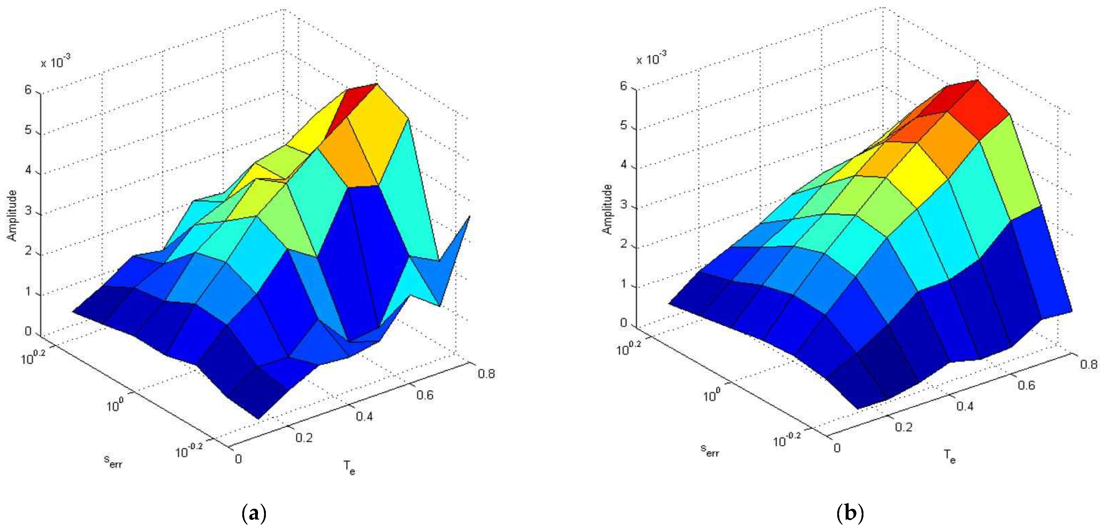
5. Simulation Analysis

The direct real-time diagnosis approach was verified using the simulation model of induction motor drive with broken rotor bars, which was extended by adding the recursive (RDFT) and Goertzel DFT (GDFT) algorithms. The amplitudes calculated at the rotor fault frequency according to (1) were analyzed and compared for different load torque and rotor speed values. In the first part of the simulation analysis, no error was assumed for the state variable estimation, so the analyzed rotor fault frequency was determined accurately. The results of application of the recursive RDFT algorithm and Goertzel algorithm in steady-state operation for different load torques and rotor speeds are presented in Figure 2. The nominal range of rotor speed and load torque values was considered. Next, the amplitudes at the rotor fault frequency were verified for different fault ranges related to the number of broken rotor bars. These results for up to six broken bars are presented in Figure 3. Limiting the number of broken bars to six resulted from the practical inoperability of a three-phase induction motor with a higher number of broken rotor bars. According to theoretical expectations, the obtained simulation results are similar for both RDFT and GDFT algorithms, assuming no impact of ADC conversion and other numerical errors and no assumption made about estimation errors. In industrial applications of induction motor drives, these conditions cannot be considered realistic due to the presence of varying estimation and numerical errors related to the limited accuracy of digital data representation. From the theoretical analysis of the idealized model calculated amplitudes, the fault-related harmonics are the same for GDFT and RDFT. In the simulation model, numerical and estimation errors do not exist. Expecting numerical and estimation errors in a limited range in real applications, some differences in the values of the estimated fault-related amplitudes are expected. Therefore, in the next step, the proposed direct fault diagnosis approach was verified including the estimation errors and the sensitivity analysis. The slip of the induction motor depends on the measured or estimated rotor speed, so the speed measurement or estimation errors were also considered. Assuming three broken rotor bars of the squirrel-cage induction motor, the amplitudes of the fault-related harmonic as in (2) were determined in the space of the variable slip estimation error serr and the variable load torque from zero to the nominal value. The results are presented in Figure 4. Considering the induced slip estimation error conditions, there is significant sensitivity difference between the RDFT and GDFT algorithms, which is an important observation for real-time fault diagnosis applications.
The obtained results presented in Figure 4 show that during the identification of the rotor-fault-related amplitude, the GDFT algorithm sensitivity to the slip estimation error is more consistent. Moreover, the irregular character of the fault harmonic amplitude obtained from RDFT for different slip estimation ranges as shown in Figure 4a makes accurate amplitude prediction more difficult, which would result in increased fault diagnosis uncertainty. For limited range of the slip estimation fault, the calculation of the fault harmonic amplitude using GDFT algorithm provides more consistent results, which implies more reliable fault diagnosis. This conclusion is useful when selecting a fault diagnosis algorithm for an induction machine. The simulation results have revealed that the GDFT algorithm is more convenient for real-time fault diagnosis, assuming slip estimation inaccuracy in the control system and considering practical implementation constraints.

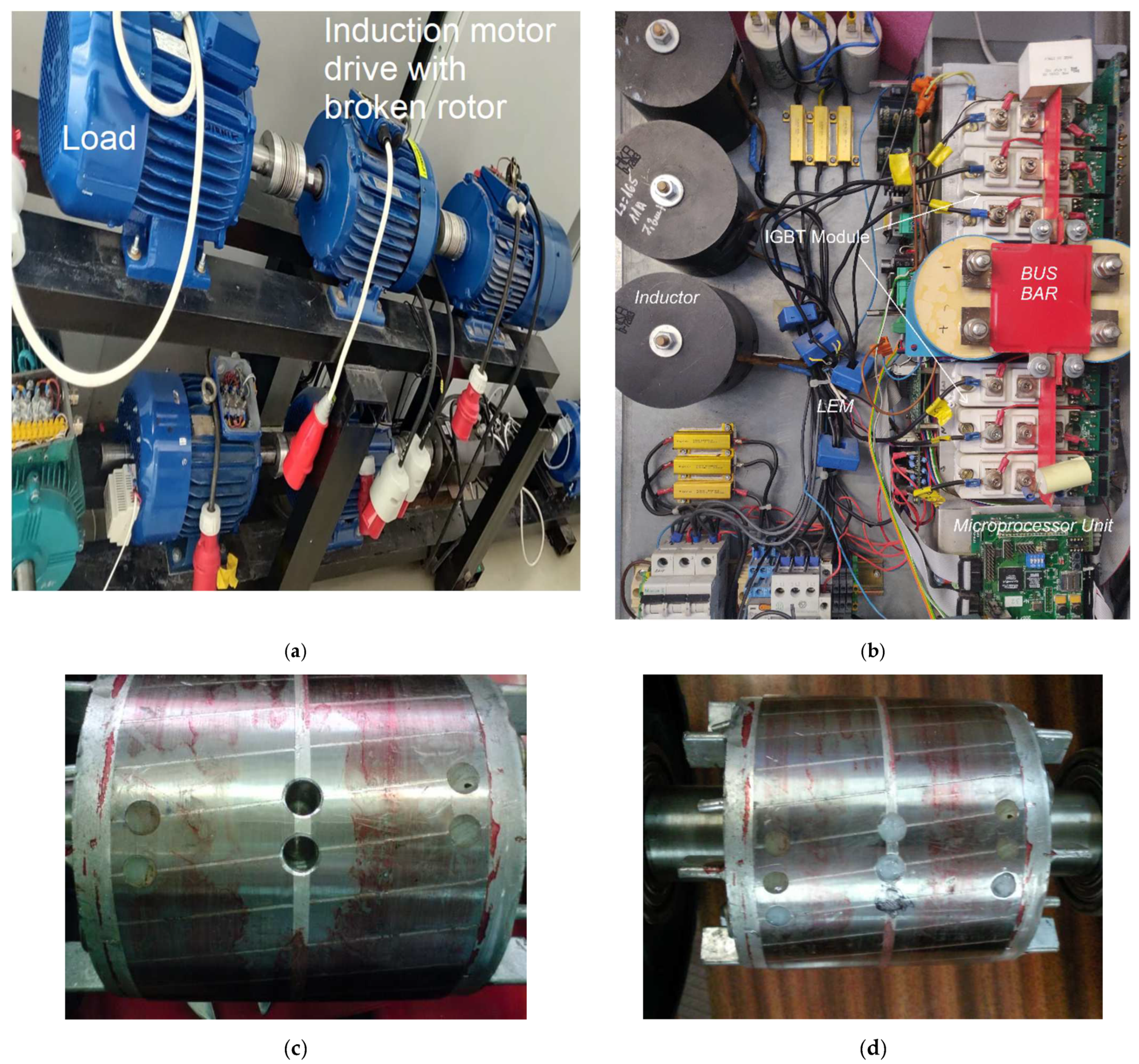
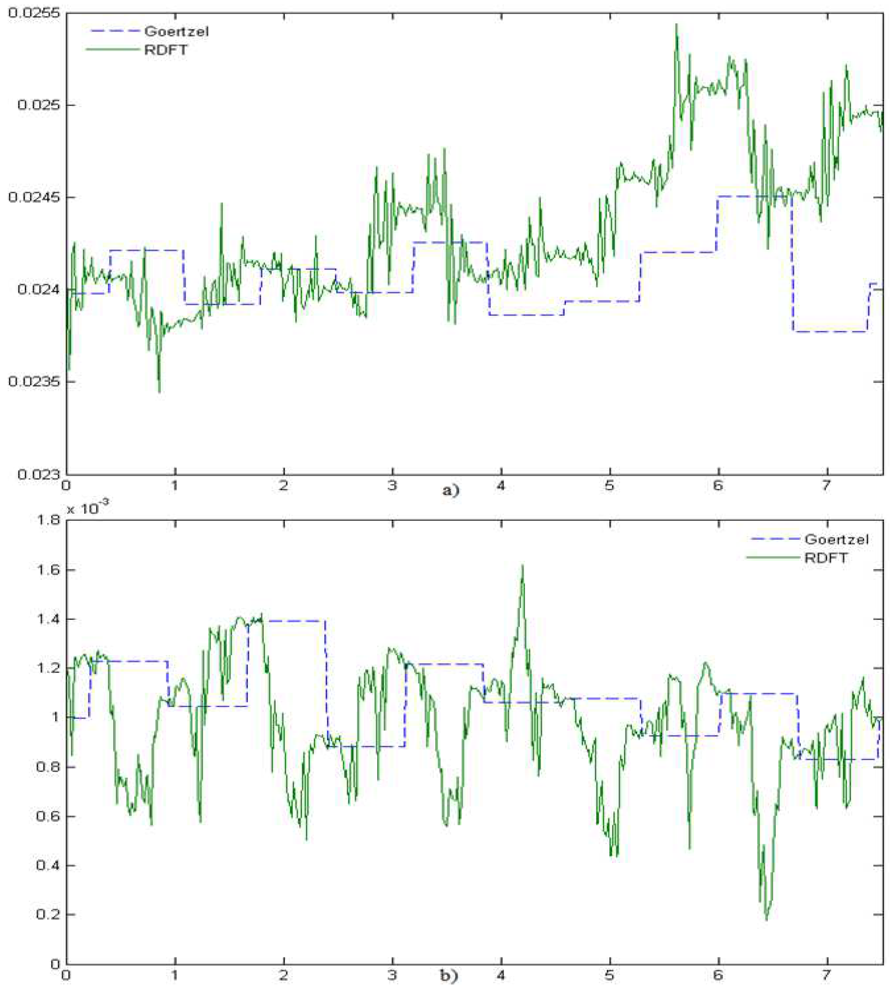
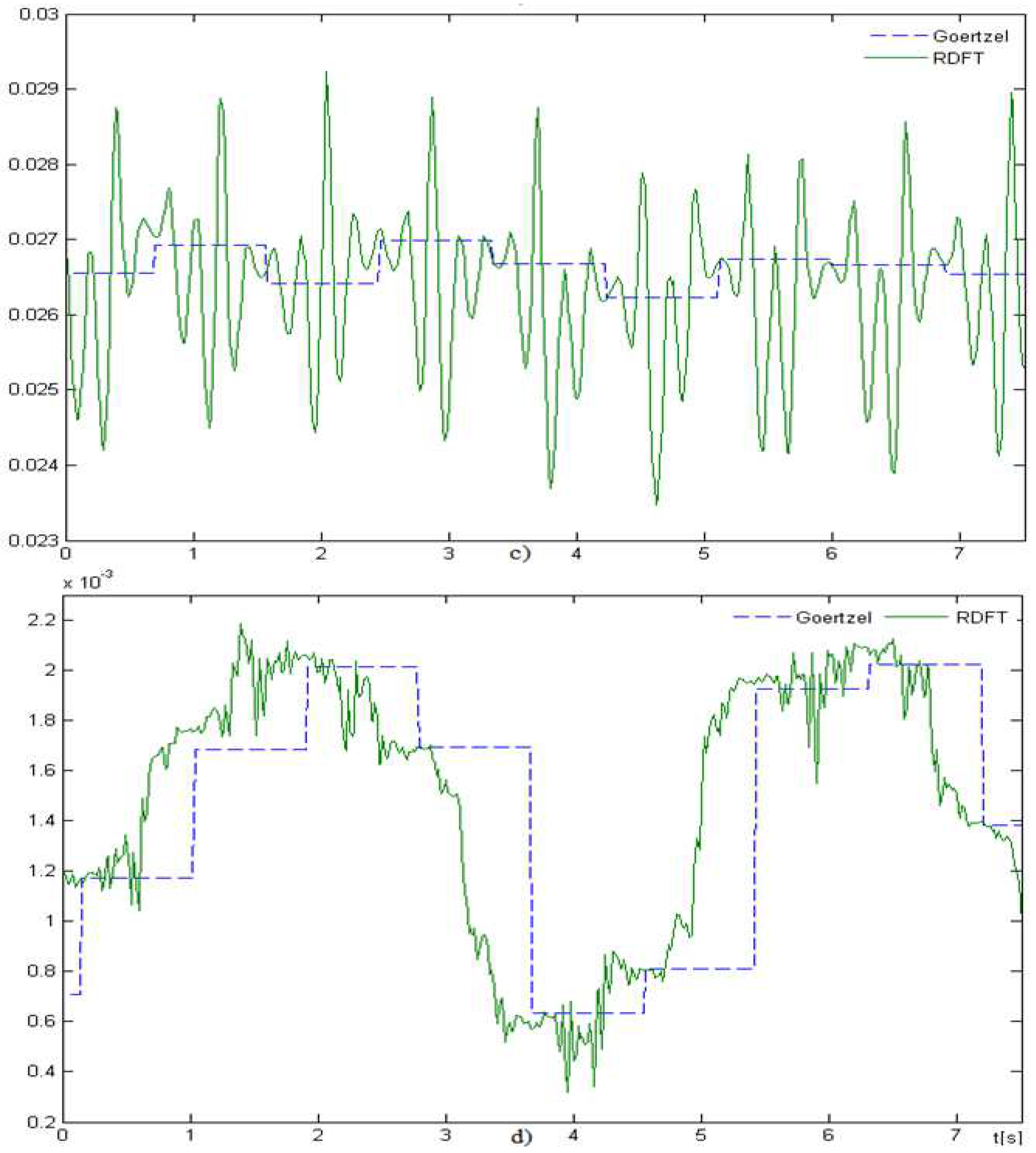
6. Experimental Results

Considering the recursive and Goertzel’s algorithms for the direct DFT harmonic calculation and analysis of the microprocessor computing time and memory availability, the modified control system including fault algorithms was implemented in a microprocessor as an application in C++ language, providing real-time fault diagnosis. The integration of the diagnosis system with the control system allowed the use of both the measured and estimated state variables to identify different faults, assuming that the frequencies of the related induced harmonics are known. The fault diagnosis algorithms were executed at the same frequency as the control system, which was set to 150 µs, being a compromise between switching and conduction loses of IGBT transistors in the applied voltage source inverter (VSI). The inverter was controlled using the SVPWM modulation. An induction motor drive with nominal power of 5.5 kW and 3 broken rotor bars was used for experimental verification, as shown in Figure 5a. The induction motor drive was fed by a voltage source inverter, and the DC circuit was fed by an IGBT-transistor-based grid inverter providing DC-link voltage stabilization and two-directional power conversion in the experimental model in Figure 5b. For comparison purposes, the experimental tests included the operation of both scalar and vector control systems of the induction motor drive. The experimental control system was based on the multiscalar model of the machine as presented in Section 3. The recursive and Goertzel DFT algorithms implemented in the microprocessor unit were tested and compared in the experimental setup of the induction motor drive. In the experimental tests, the measured phase stator’s current signal was selected for analyzing whether the rotor-related harmonic exists and estimating its amplitude for diagnostic reasoning related to the assessment of the broken rotor range. The implementation of the algorithm in the microprocessor is not complex, so it can be easily adopted in industrial applications. However, for a broken rotor, according to the relevant equation, the motor slip is required to be accurately measured or estimated.
The real-time direct broken rotor fault diagnostics using recursive and Goertzel DFT algorithms was tested using broken and healthy rotors in a scalar and vector-controlled induction motor drive. The results of the real-time operation of the implemented diagnostic algorithms are presented in Figure 6. Both algorithms are convergent to the same value, however, there are significant differences in instantaneous values. The recursive DFT application corresponding to the initial assumptions of the implementation provides higher frequency updates of the broken rotor’s fault-related amplitude, but the observed oscillating character of the identification leads to higher oscillations of the instantaneous amplitude values, especially for the vector-controlled topology of the induction motor drive, as shown in Figure 6c. The Goertzel DFT algorithm application is updated after filling the window of samples, thus providing a lower frequency of diagnostic signal update but also lower deviation of the instantaneous rotor fault related amplitude from the mean value in steady-state operation. In all cases, the real-time tracking of the fault related harmonic signal was performed for a typical sampling frequency 3.3 kHz, imposed by the assumption for the control system synthesis.
The selection of the method and its parameters needs to be adapted to the type of identified fault and assumed time constraints for the diagnosis. For the adopted implementation of direct harmonic calculation algorithms, RDFT provides shorter time of the fault detection process, while GDFT provides higher accuracy and consistency of fault range identification. A significant difference in the real-time direct fault diagnosis between RDFT and GDFT is related to the steady-state operation requirement during the harmonic analysis, which is difficult to achieve in the industrial operation of the drive due to non-ideal load torque and the impact of the control system on state variables. An accurate estimation of harmonic fault frequency leads to identifying the rotor-fault-related harmonic amplitude as being significantly higher compared to a healthy rotor, providing that the broken rotor fault’s symptom is clearly identified. The proposed broken rotor fault identification approach was tested in the full range of operation of the induction motor drive. The results of the rotor fault diagnosis for scalar and vector control in the space of variable rotor speed and load torque are compared in Table 1 and Table 2. The selection of scalar- (U/f = const.) and vector-controlled IM motor drives is justified by the analysis of the impact of the control system (PI controllers) on the accuracy of tracking the amplitude of the fault related harmonic. In the simulations, the range of the load torque and rotor speed values selected to verify the proposed approach for different frequencies of fault-related harmonics and different amplitudes of machine operation was up to their nominal values. The amplitude of the fault related harmonic can be scaled by load torque for diagnostic reasoning about the range of the fault. In the real-time fault diagnosis application, when the amplitudes of the fault-related harmonic are averaged for a longer period of time, for GDFT, they are convergent to the true fault symptom value in accordance to the theory, while in RDFT, an accumulation of the errors is observed, which requires periodical reset. The experimental verification shown in Table 1 and Table 2 proves the capability of fast diagnosis using the proposed diagnosis approach, which can be useful for fault-tolerant control [27].

7. Conclusions

The presented real-time fault diagnosis in the frequency domain using RDFT and GDFT algorithms was theoretically investigated and experimentally verified, including a sensitivity analysis, on an induction motor drive with a broken rotor as an example. The experimental test results are presented for scalar and vector control systems of the induction motor drive. The requirement of accurate motor slip estimation is discussed, and the proposed approach is implemented for real-time rotor fault frequency determination. The experimental tests have shown an acceptable slip estimation accuracy for broken rotor fault harmonic frequency estimation, which provides accurate fault harmonic amplitude identification and reliable real-time fault diagnosis. The model of an asymmetric induction motor used for the sensitivity analysis has shown that the application of the proposed method requires high-accuracy motor slip identification, which implies the need for a high-resolution encoder in case of rotor speed measurement or an accurate speed estimator, including transient states, in the sensorless induction motor drive. The experimentally verified algorithms for direct fast real-time diagnosis have proven the potential and improved reliability of the early-stage fault diagnosis and therefore can be used for implementation of the fault tolerant control for variable speed induction motor drives. Moreover, the proposed approach can be used for fault detection, extraction, and identification processes. The presented frequency-domain direct fault diagnosis is not limited to induction motor drives. Regarding the electric machine fault theory, it is also applicable for different electric drives and different faults. By relying it on the mathematical model of fault, the complexity of the real-time fault diagnosis has been decreased, which supports its capability of real-time identification of other faults by the microprocessor. In the proposed approach, the application of GDRFT and RDFT for fault diagnosis via direct real-time tracking of one or more fault-related harmonics significantly improves the efficiency of the diagnosis because registering the data for calculating all harmonics in the spectra up to the Nyquist frequency, as in FFT, and further analysis of the spectra is omitted. The proposed approach has been proven to be efficient and convenient for real-time automated diagnostics in a broad range of applications.

Author Contributions

Conceptualization, P.K. and D.W.; methodology, D.W.; software, P.K.; validation, D.W.; formal analysis, P.K.; investigation, D.W.; resources, P.K.; data curation, D.W.; writing—original draft preparation, P.K.; writing—review and editing, P.K. and D.W.; visualization, P.K.; supervision, D.W.; project administration, P.K.; funding acquisition, P.K. All authors have read and agreed to the published version of the manuscript.

Funding

This research was funded by The National Centre of Science grant 7158/B/T02/2011/40.

Institutional Review Board Statement

Not applicable.

Informed Consent Statement

Not applicable.

Conflicts of Interest

The authors declare no conflict of interest.

References

  1. Riera-Guasp, M.; Antonino-Daviu, J.A.; Capolino, G.-A. Advances in Electrical Machine, Power Electronic, and Drive Condition Monitoring and Fault Detection: State of the Art. IEEE Trans. Ind. Electron. 2014, 62, 1746–1759. [Google Scholar] [CrossRef]
  2. Merizalde, Y.; Hernández-Callejo, L.; Duque-Perez, O. State of the Art and Trends in the Monitoring, Detection and Diagnosis of Failures in Electric Induction Motors. Energies 2017, 10, 1056. [Google Scholar] [CrossRef] [Green Version]
  3. Terron-Santiago, C.; Martinez-Roman, J.; Puche-Panadero, R.; Sapena-Bano, A. A Review of Techniques Used for Induction Machine Fault Modelling. Sensors 2021, 21, 4855. [Google Scholar] [CrossRef] [PubMed]
  4. Tian, Y.; Guo, D.; Zhang, K.; Jia, L.; Qiao, H.; Tang, H. A Review of Fault Diagnosis for Traction Induction Motor. In Proceedings of the 2018 37th Chinese Control Conference (CCC), Wuhan, China, 25–27 July 2018; pp. 5763–5768. [Google Scholar]
  5. Chen, H.; Jiang, B. A Review of Fault Detection and Diagnosis for the Traction System in High-Speed Trains. IEEE Trans. Intell. Transp. Syst. 2019, 21, 450–465. [Google Scholar] [CrossRef]
  6. Kim, B.; Lee, K.; Yang, J.; Bin Lee, S.; Wiedenbrug, E.J.; Shah, M.R. Automated Detection of Rotor Faults for Inverter-Fed Induction Machines Under Standstill Conditions. IEEE Trans. Ind. Appl. 2010, 47, 55–64. [Google Scholar] [CrossRef]
  7. Li, L.; Lu, W.; Wang, X.; Li, Z. A frequency domain feature based cascade classifier and its application to fault diagnosis. In Proceedings of the 28th Chinese Control and Decision Conference, CCDC 2016, Yinchuan, China, 28–30 May 2016; Volume 2, pp. 5957–5961. [Google Scholar] [CrossRef]
  8. Wang, Z.; Yang, J.; Li, H.; Zhen, D.; Xu, Y.; Gu, F. Fault Identification of Broken Rotor Bars in Induction Motors Using an Improved Cyclic Modulation Spectral Analysis. Energies 2019, 12, 3279. [Google Scholar] [CrossRef] [Green Version]
  9. Moussa, M.A.; Boucherma, M.; Khezzar, A. A Detection Method for Induction Motor Bar Fault Using Sidelobes Leakage Phenomenon of the Sliding Discrete Fourier Transform. IEEE Trans. Power Electron. 2016, 32, 5560–5572. [Google Scholar] [CrossRef]
  10. Sahraoui, M.; Cardoso, A.J.M.; Ghoggal, A. The Use of a Modified Prony Method to Track the Broken Rotor Bar Characteristic Frequencies and Amplitudes in Three-Phase Induction Motors. IEEE Trans. Ind. Appl. 2014, 51, 2136–2147. [Google Scholar] [CrossRef]
  11. Skowron, M.; Orlowska-Kowalska, T.; Wolkiewicz, M.; Kowalski, C.T. Convolutional Neural Network-Based Stator Current Data-Driven Incipient Stator Fault Diagnosis of Inverter-Fed Induction Motor. Energies 2020, 13, 1475. [Google Scholar] [CrossRef] [Green Version]
  12. Rinanto, N.; Adhitya, R.Y.; Sarena, S.T.; Kautsar, S.; Munadhif, I.; Setyoko, A.S.; Syai’In, M.; Soeprijanto, A. Rotor bars fault detection by DFT spectral analysis and Extreme Learning Machine. In Proceedings of the 2016 International Symposium on Electronics and Smart Devices, ISESD 2016, Bandung, Indonesia, 29–30 November 2016; pp. 103–108. [Google Scholar] [CrossRef]
  13. Kolodziejek, P.; Bogalecka, E. Broken rotor bar impact on sensorless control of induction machine. COMPEL Int. J. Comput. Math. Electr. Electron. Eng. 2009, 28, 540–555. [Google Scholar] [CrossRef]
  14. Puche-Panadero, C.R.; Pineda-Sanchez, M.; Riera-Guasp, M.; Roger-Folch, J.; Hurtado-Perez, E.; Perez-Cruz, J. Improved Resolution of the MCSA Method Via Hilbert Transform, Enabling the Diagnosis of Rotor Asymmetries at Very Low Slip. IEEE Trans. Energy Convers. 2013, 24, 52–59. [Google Scholar] [CrossRef]
  15. Kral, C.; Pirker, F.; Pascoli, G. The impact of inertia on rotor faults effects theoretical aspects of the Vienna Monitoring Method. In Proceedings of the 2007 IEEE International Symposium on Diagnostics for Electric Machines, Power Electronics and Drives, SDEMPED, Cracow, Poland, 6–7 September 2007; pp. 77–82. [Google Scholar] [CrossRef]
  16. Luo, M.; Liu, Z.; Zhou, H.; Zhang, X.; Gao, F. Diagnosis simulation of broken rotor bars in squirrel cage induction motor fed with variable frequency power. In Proceedings of the 27th Chinese Control Conference CCC, Kunming, China, 16–18 July 2008; pp. 88–92. [Google Scholar] [CrossRef]
  17. Gritli, Y.; Bellini, A.; Rossi, C.; Casadei, D.; Filippetti, F.; Capolino, G.A. Condition monitoring of mechanical faults in induction machines from electrical signatures: Review of different techniques. In Proceedings of the 2017 IEEE 11th International Symposium on Diagnostics for Electric Machines, Power Electronics and Drives, SDEMPED 2017, Tinos, Greece, 29 August–1 September 2017; Volume 2017, pp. 77–84. [Google Scholar] [CrossRef]
  18. Nemec, M.; Ambrožič, V.; Fišer, R.; Nedeljković, D.; Drobnič, K. Induction motor broken rotor bar detection based on rotor flux angle monitoring. Energies 2019, 12, 794. [Google Scholar] [CrossRef] [Green Version]
  19. Ayhan, B.; Chow, M.-Y.; Song, M.-H. Multiple Signature Processing-Based Fault Detection Schemes for Broken Rotor Bar in Induction Motors. IEEE Trans. Energy Convers. 2005, 20, 336–343. [Google Scholar] [CrossRef] [Green Version]
  20. Lu, B.; Paghda, M. Induction motor rotor fault diagnosis using wavelet analysis of one-cycle average power. In Proceedings of the IEEE Applied Power Electronics Conference and Exposition APEC 2018, San Antonio, TX, USA, 4–8 March 2018; pp. 1113–1118. [Google Scholar] [CrossRef]
  21. Kołodziejek, P.; Bogalecka, E. Broken rotor symptoms in the sensorless control of induction machine. COMPEL Int. J. Comput. Math. Electr. Electron. Eng. 2011, 31, 237–247. [Google Scholar] [CrossRef]
  22. Kia, S.H.; Henao, H.; Capolino, G.A.; Martis, C. Induction machine broken bars fault detection using stray flux after supply disconnection. IECON Proc. 2006, 2006, 1498–1503. [Google Scholar] [CrossRef]
  23. Jornet, A.; Espinosa, A.G.; Romeral, L.; Cusidó, J.; Ortega, J.A. Double frequency test for detecting faults in induction machines. IECON Proc. 2005, 2005, 1516–1521. [Google Scholar] [CrossRef]
  24. Drif, M.; Cardoso, A.J.M. The Use of the Instantaneous-Reactive-Power Signature Analysis for Rotor-Cage-Fault Diagnostics in Three-Phase Induction Motors. IEEE Trans. Ind. Electron. 2009, 56, 4606–4614. [Google Scholar] [CrossRef]
  25. Touhami, O.; Fadel, M. Detection of Broken Rotor Bars and Stator Faults in Squirrel-Cage Induction Machine by Spectral Analysis. In Proceedings of the 2007 Thirty-Ninth Southeastern Symposium on System Theory, Macon, GA, USA, 4−7 March 2007; pp. 274–278. [Google Scholar] [CrossRef]
  26. Pakhaliuk, B.; Shevchenko, V.; Mućko, J.; Husev, O.; Lukianov, M.; Kołodziejek, P.; Strzelecka, N.; Strzelecki, R. Optimal Rotating Receiver Angles Estimation for Multicoil Dynamic Wireless Power Transfer. Energies 2021, 14, 6144. [Google Scholar] [CrossRef]
  27. Adamowicz, M.; Szewczyk, J. SiC-Based Power Electronic Traction Transformer (PETT) for 3 kV DC Rail Traction. Energies 2020, 13, 5573. [Google Scholar] [CrossRef]
  28. Kołodziejek, P. State and control system variables sensitivity to rotor asymmetry in the induction motor drive. COMPEL Int. J. Comput. Math. Electr. Electron. Eng. 2012, 32, 142–152. [Google Scholar] [CrossRef]
  29. Wlas, M.; Galla, S.; Kouzou, A.; Kolodziejek, P. Analysis of an Energy Management System of a Small Plant Connected to the Rural Power System. Energies 2022, 15, 719. [Google Scholar] [CrossRef]
  30. Wu, Y.; Liu, Z.X.; Li, R.Y. Fault diagnosis way based on subsection spectrum zoom analysis by CZT for squirrel cage induction motors. In Proceedings of the 2008 International Conference on Condition Monitoring and Diagnosis, Beijing, China, 21–24 April 2008; pp. 208–211. [Google Scholar] [CrossRef]
  31. Krzemiński, Z. Cyfrowe Sterowanie Maszynami Asynchronicznymi; Gdansk University of Technology: Gdańsk, Poland, 2000. (In Polish) [Google Scholar]
  32. Wachowiak, D. A Universal Gains Selection Method for Speed Observers of Induction Machine. Energies 2021, 14, 6790. [Google Scholar] [CrossRef]
  33. Wachowiak, D. Genetic Algorithm Approach for Gains Selection of Induction Machine Extended Speed Observer. Energies 2020, 13, 4632. [Google Scholar] [CrossRef]
  34. Cooley, J.W.; Tukey, J.W. An Algorithm for the Machine Calculation of Complex Fourier Series. Math. Comput. 1965, 19, 297–301. [Google Scholar] [CrossRef]
  35. Gerard, G. An Algorithm for the Evaluation of Finite Trigonometric Series. Am. Math. Mon. 1958, 65, 34–35. [Google Scholar]
Figure 1. Integrated control system and fault diagnostic algorithms between ADC interrupts of the microcontroller.
Energies 15 01244 g001
Figure 2. The amplitude of the rotor fault related harmonic obtained using (a) RDFT and (b) Goertzel’s algorithm for variable number of broken rotor bars and variable electromagnetic torque and rotor speed, with no slip estimation error assumed.
Energies 15 01244 g002
Figure 3. The amplitude of the rotor fault related harmonic obtained using (a) RDFT and (b) Goertzel’s algorithm for a variable number of broken rotor bars.
Energies 15 01244 g003
Figure 4. The amplitude of broken rotor harmonic at estimated frequency obtained using (a) RDFT and (b) GDFT algorithms for variable slip estimation error.
Energies 15 01244 g004
Figure 5. (a) Experimental induction motor drive setup with controlled load, (b) back-to-back IGBT-based inverter, (c) rotor with 2 broken rotor bars, (d) rotor with 3 broken rotor bars.
Energies 15 01244 g005
Figure 6. Real-time amplitude estimation of the rotor fault related harmonic for Goertzel and RDFT algorithms at ωr = 0.65, TL = 0.72 and (a) Scalar control V/f = const and rotor fault, (b) Scalar control V/f = const and healthy rotor, (c) Multiscalar vector control and broken rotor, (d) Multiscalar vector control and healthy rotor.
Energies 15 01244 g006aEnergies 15 01244 g006b
Table 1. Amplitudes of the rotor-fault-related harmonic at scalar control of rotor with 3 broken bars.
ωrTeGDFT (dB)RDFT (dB)
0.30.2540.840.8
0.30.519.119.1
0.30.7213.512.0
0.650.2520.820.8
0.650.525.125.1
0.650.7228.027.6
10.2522.322.3
10.519.119.1
10.7213.413.4
Table 2. Amplitudes of the rotor-fault-related harmonic at vector control.
ωrTeGDFT (dB)RDFT (dB)
0.30.2540.840.8
0.30.519.119.1
0.30.7213.512.0
0.650.2520.820.8
0.650.525.125.1
0.650.7228.027.6
10.2522.322.3
10.519.119.1
10.7213.413.4
Publisher’s Note: MDPI stays neutral with regard to jurisdictional claims in published maps and institutional affiliations.

