
Multi-Objective Optimization of Parameters of Channels with Staggered Frustum of a Cone Based on Response Surface Methodology


Abstract
:1. Introduction
2. Physical Model and Numerical Methods
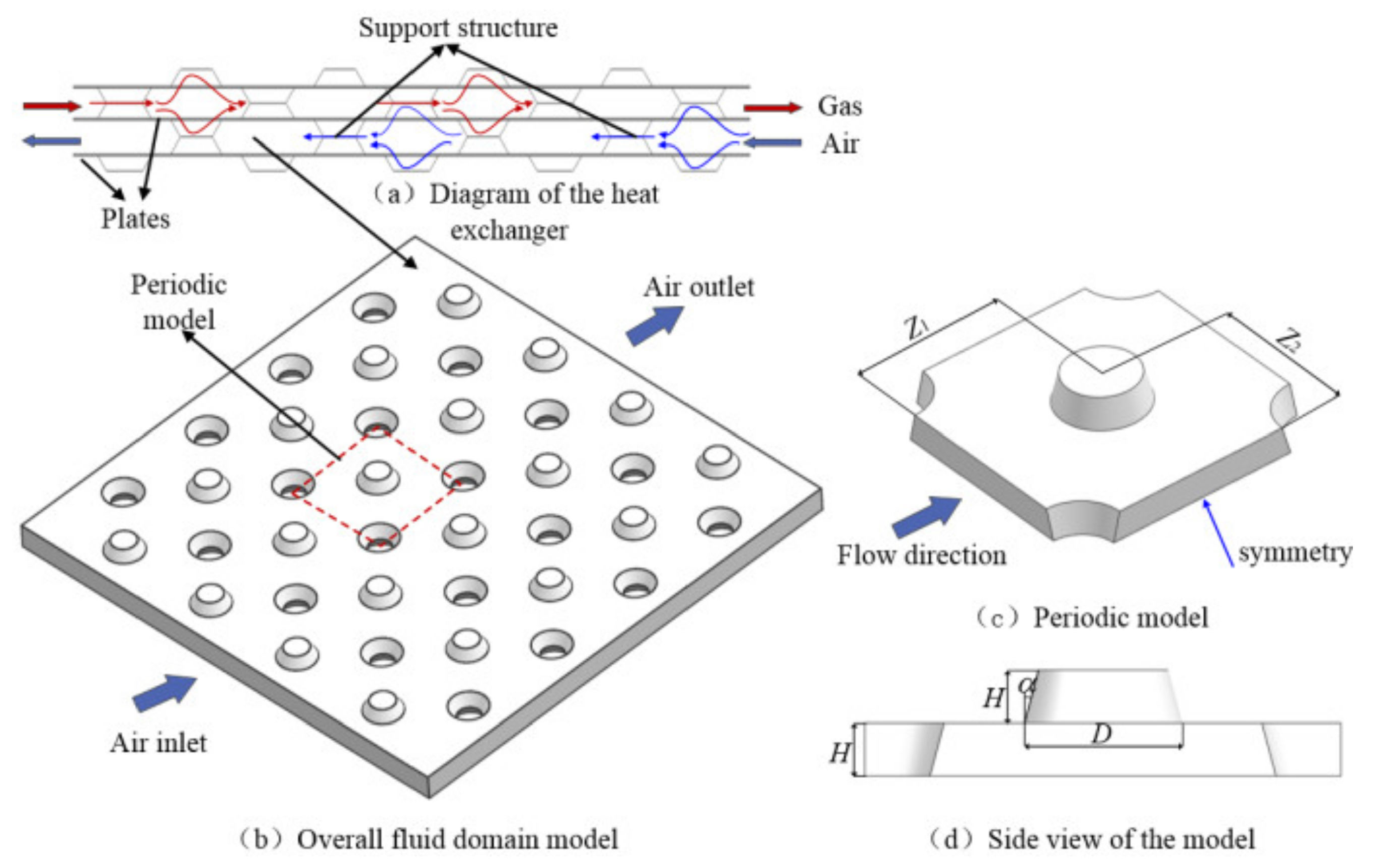
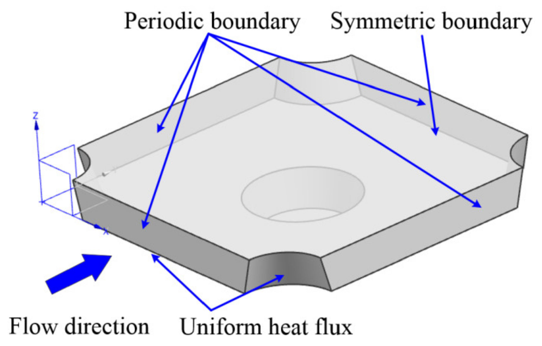
2.1. Physical Model
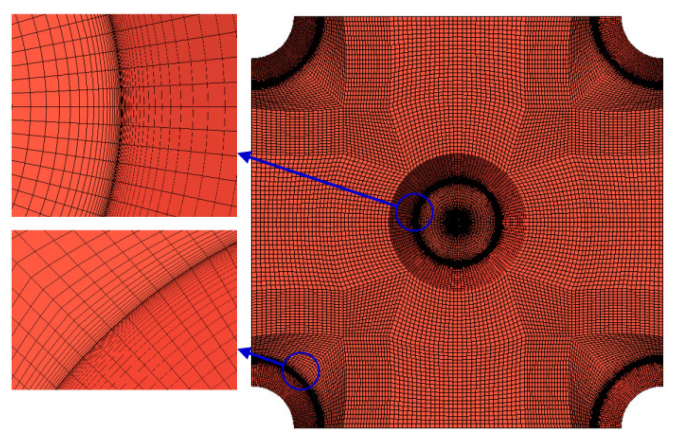
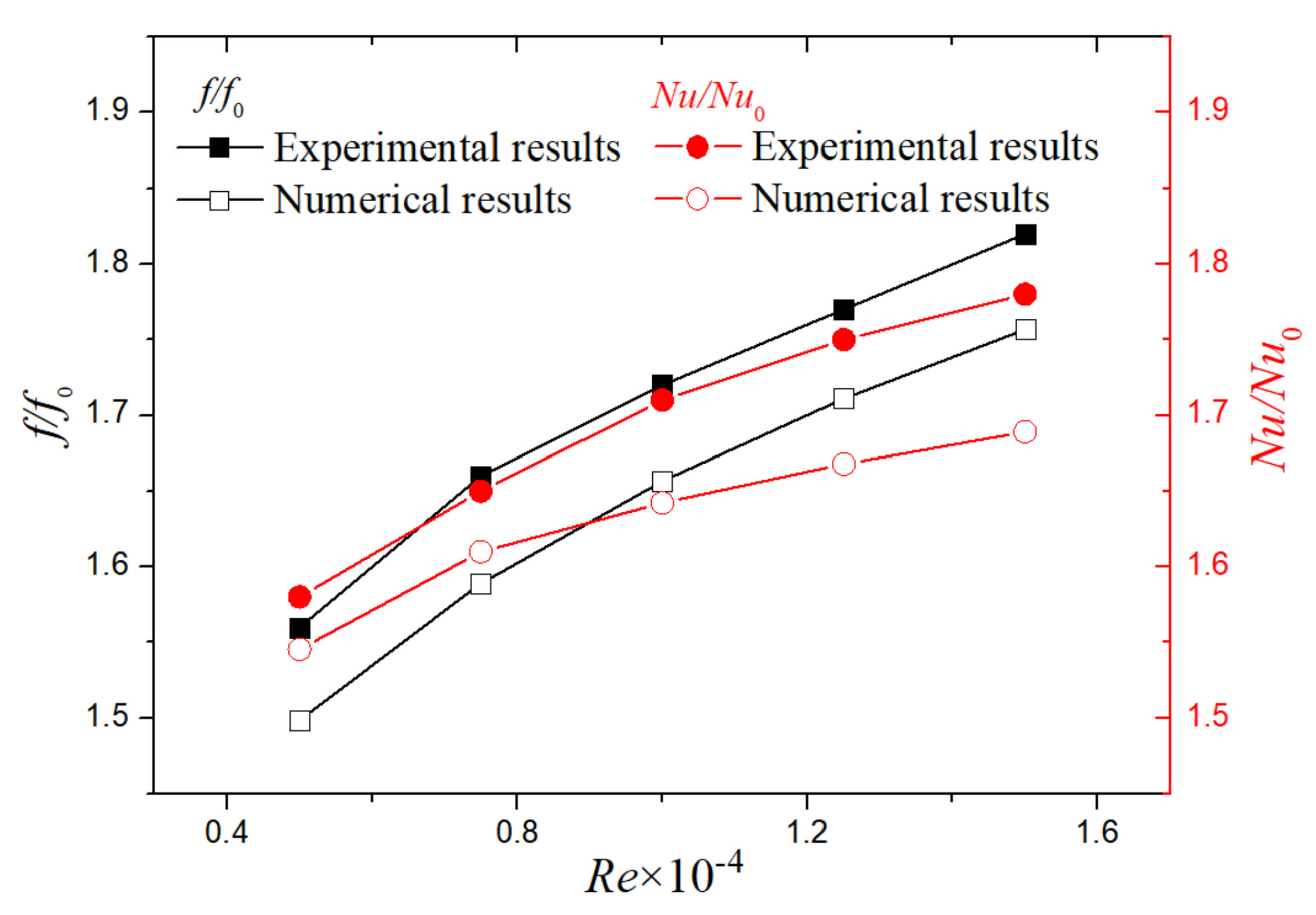
2.2. Numerical Methods
2.3. Data Reduction
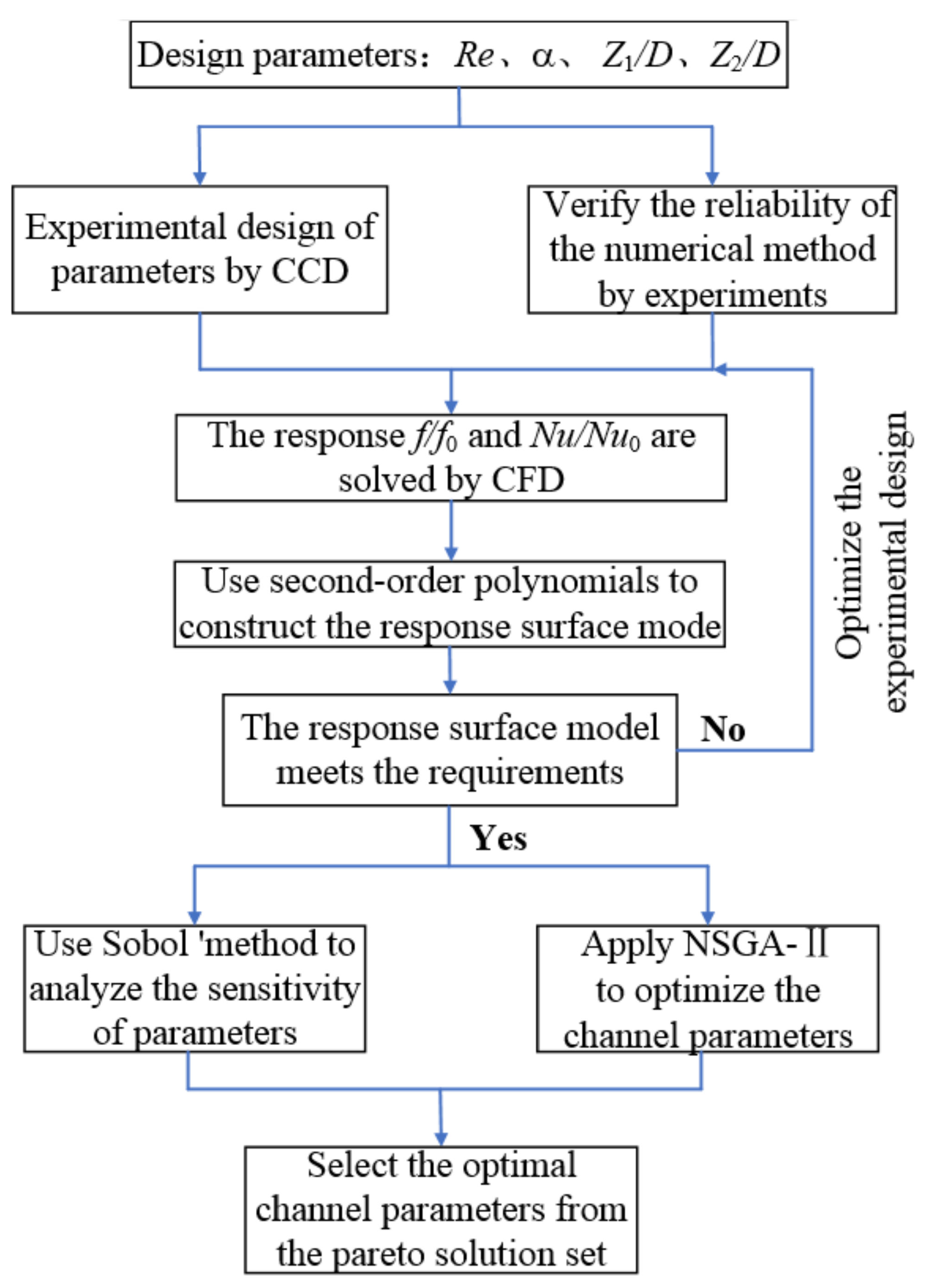
3. Optimization Methods
3.1. Response Surface Methodology and Experimental Design
3.2. Parameter Sensitivity Analysis Based on Sobol’s method
3.3. Optimization Process of the Channel with Frustums of a Cone
4. Results Analysis and Discussion
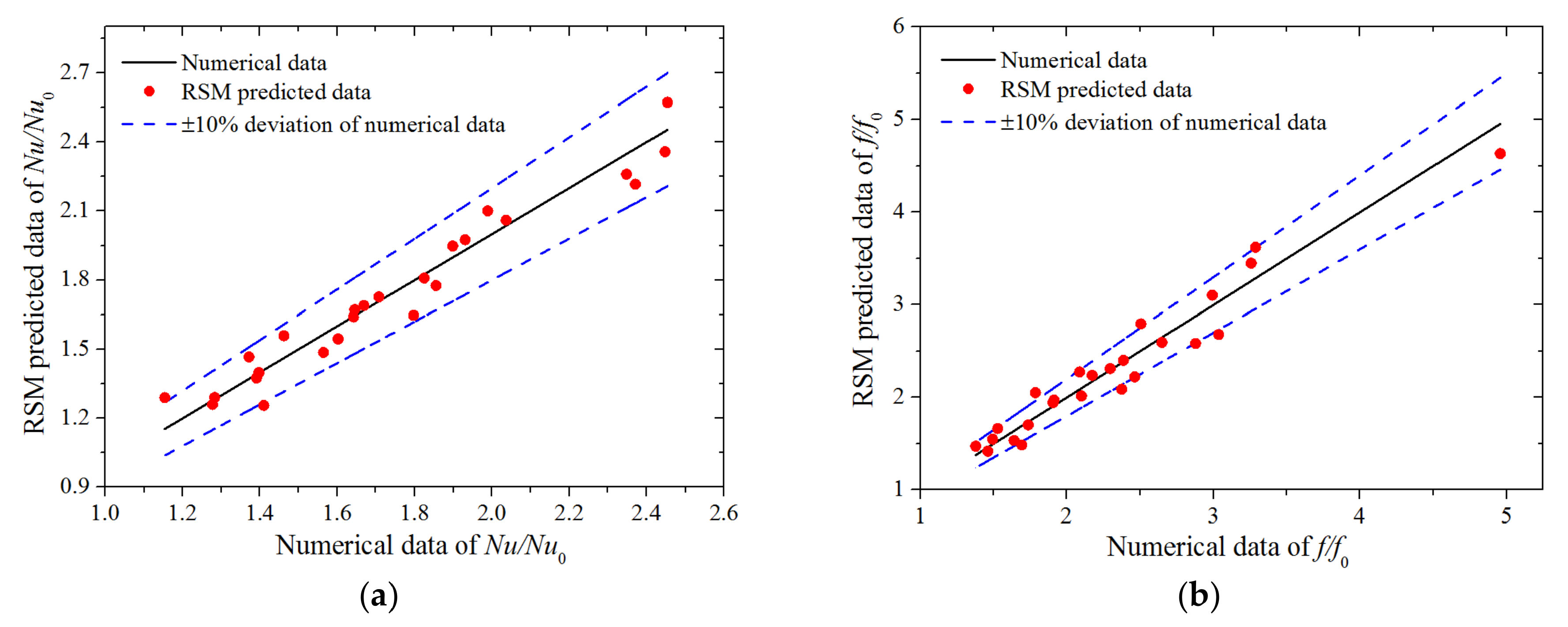
4.1. Construction of Response Surface Model
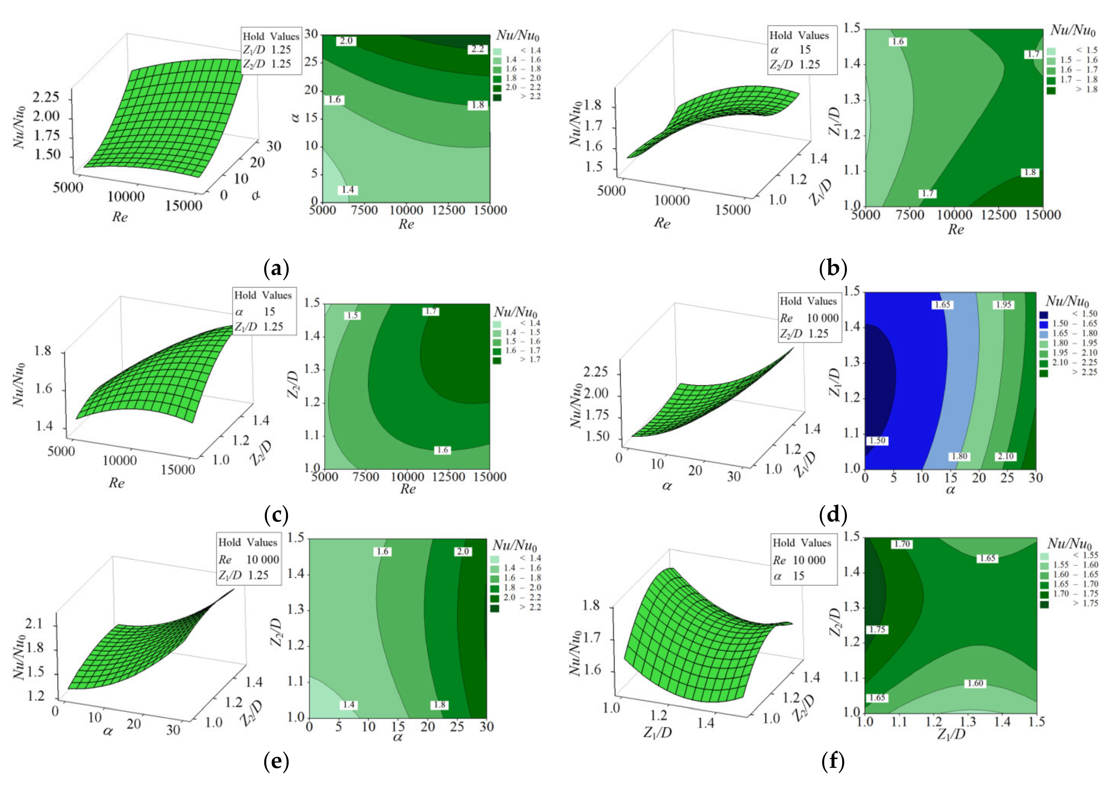
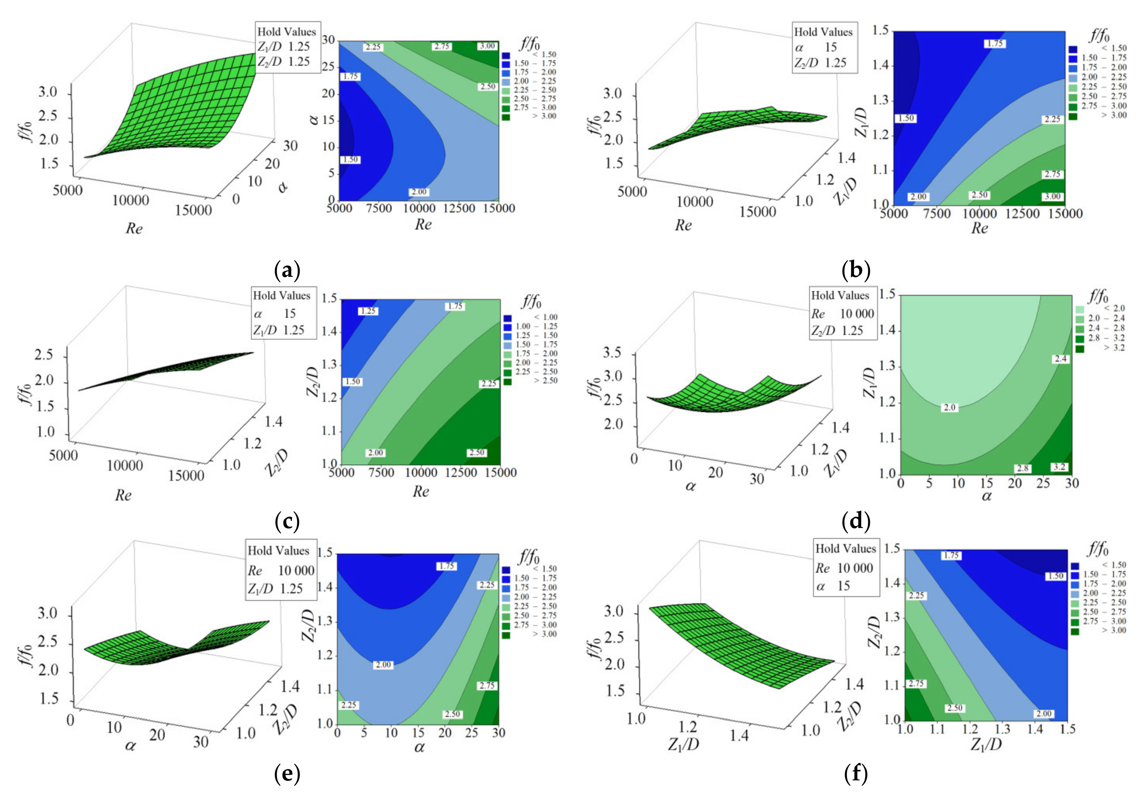
4.2. Effect of Channel Parameters on Flow and Heat Transfer
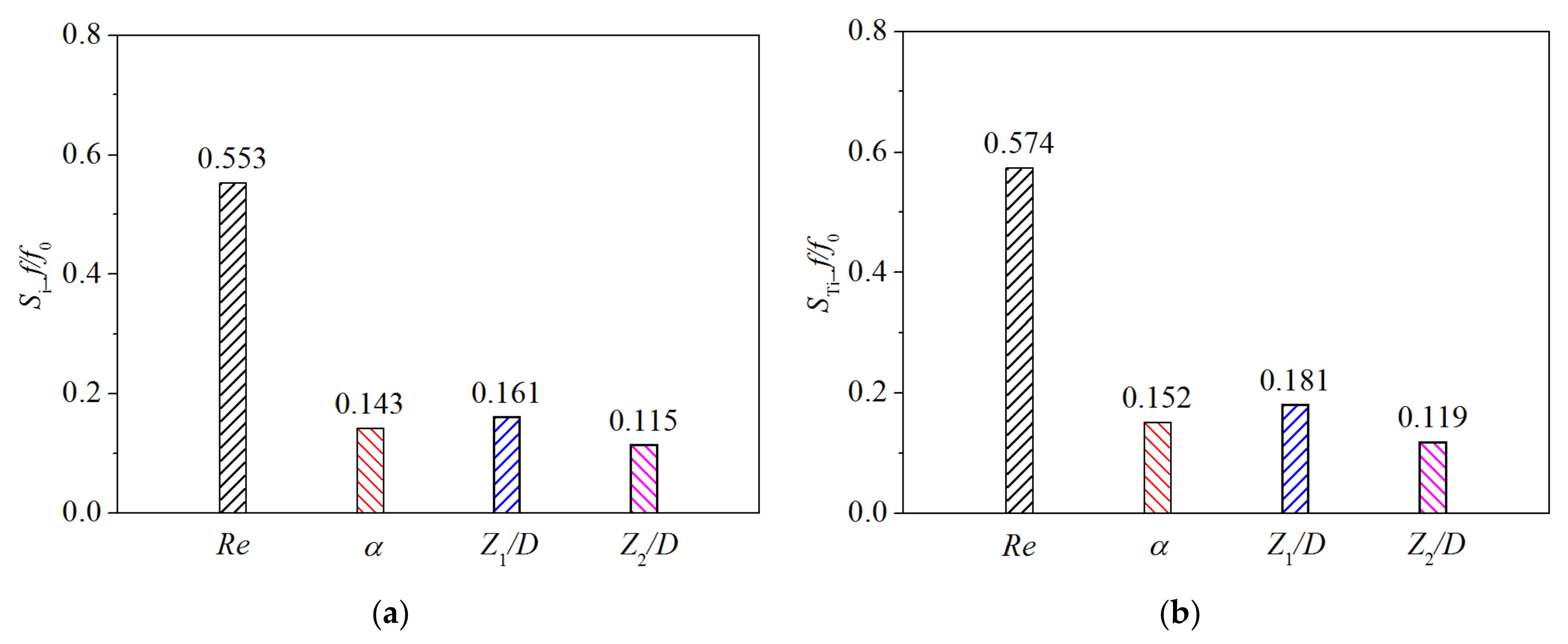
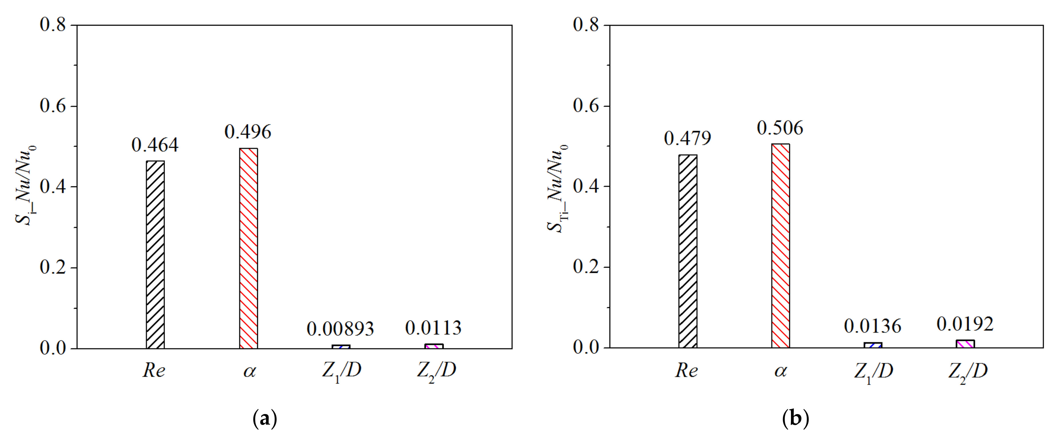
4.3. Sensitivity Analysis of the Channel Parameters
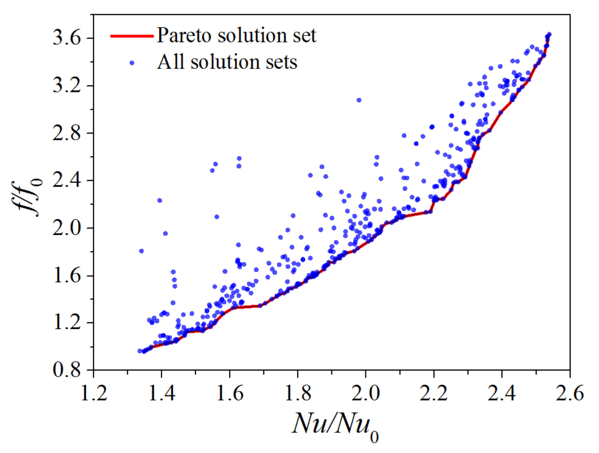
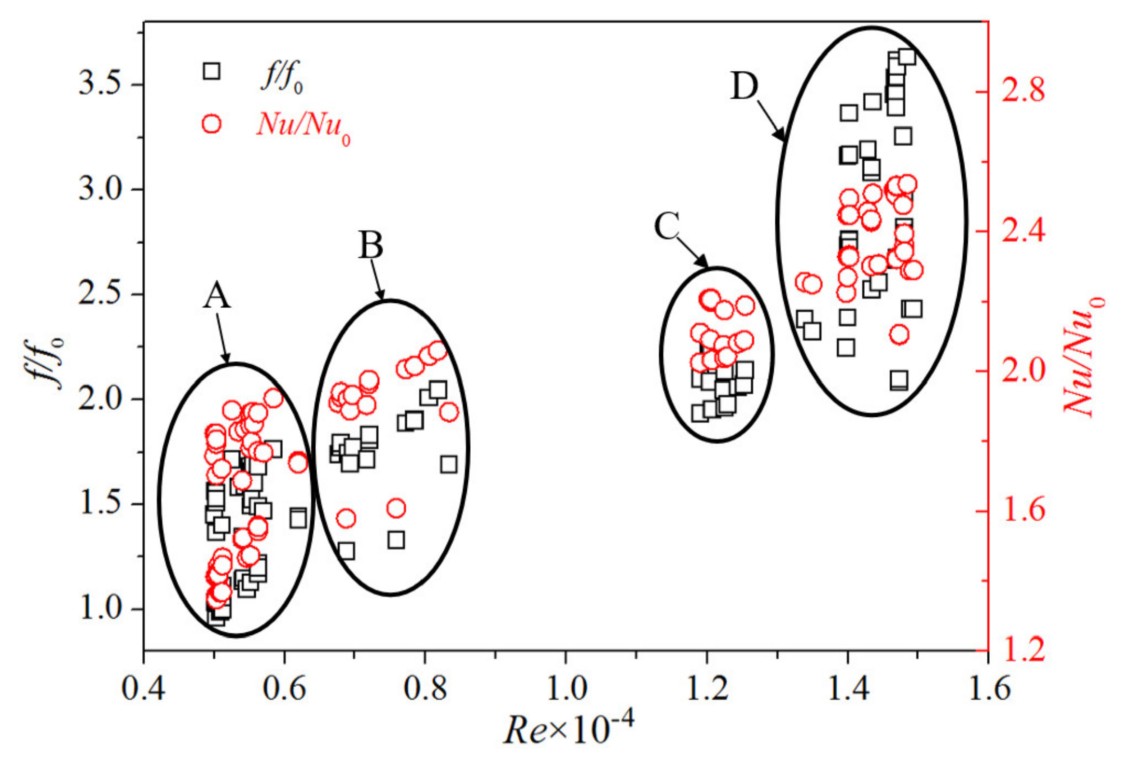
4.4. Multi-Objective Optimization Results of the Parameters
5. Conclusions
- (1)
- The second-order response surface models obtained by CCF have small errors and high accuracy. When the response is Nu/Nu0, the RMSE of the model is 0.1048 and R2 is 0.9491. When the response is f/f0, the RMSE of the model is 0.2445 and R2 is 0.9399.
- (2)
- Compared with Z1/D and Z2/D, α and Re have the greatest impact on the Nu/Nu0 of the channels. Parameter Re has the greatest influence on the f/f0 of the channels, while α, Z1/D and Z2/D have the same, small influence on the f/f0 of the channels.
- (3)
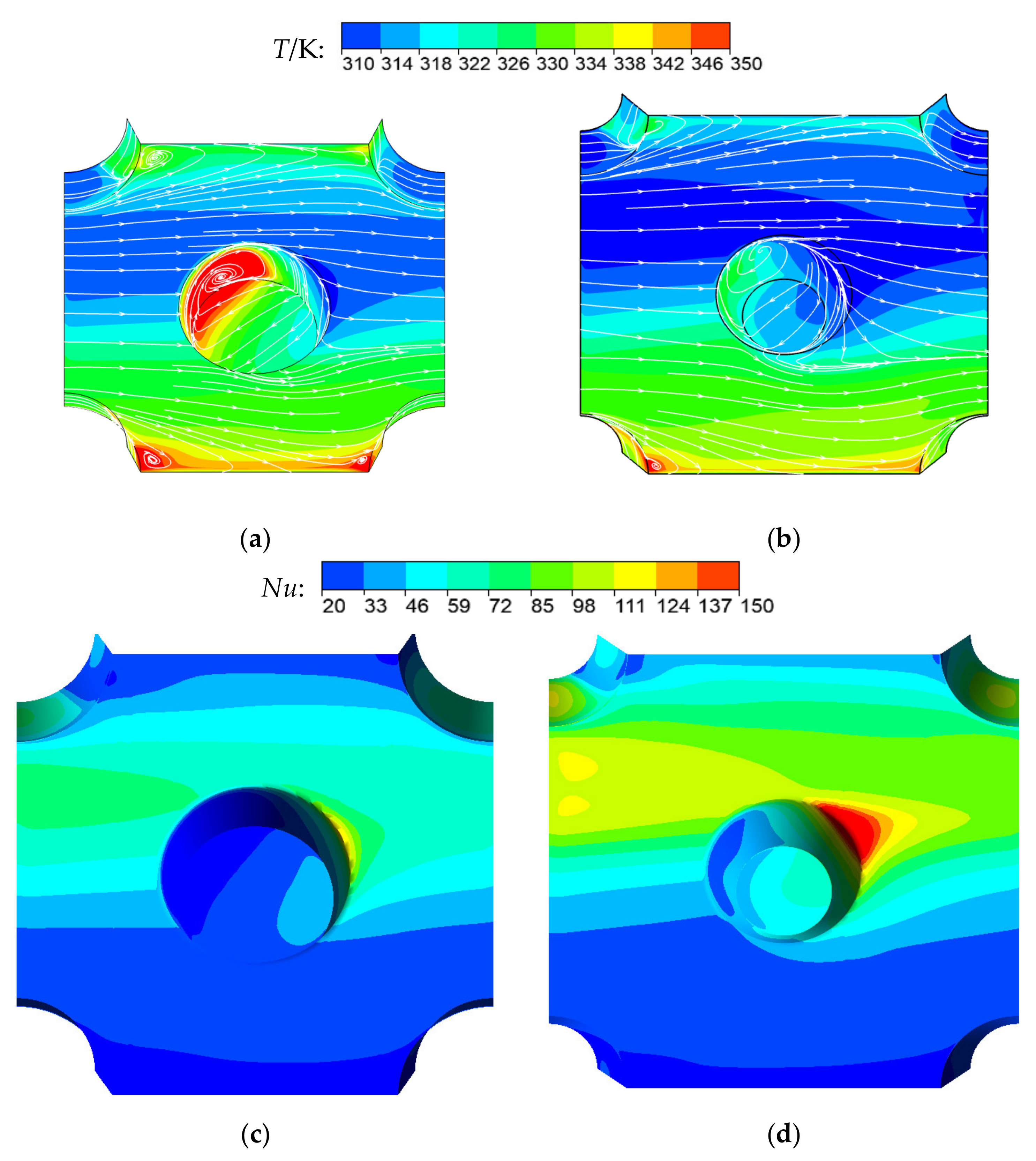
- By comparing the reference channel with the optimized channel, the results show that the optimized channel improves the vortexes at the bottom of the concave and upstream and downstream of the convex, so that the heat transfer wall of the channel has lower temperature distribution and higher Nu distribution.
- (4)
- Compared with the reference channel, the Nu/Nu0 of the four optimized channels are increased by 9.70%, 21.82%, 26.06% and 27.88%, respectively; the f/f0 decreased by 19.89%, 1.05%, –7.85% and –9.42%, respectively. The Nu/Nu0 of the channels increased by 21.36% on average and the f/f0 declined by 9.16% on average, which demonstrates that the optimization method of the channel parameters in the present study has a good effect.
Author Contributions
Funding
Institutional Review Board Statement
Informed Consent Statement
Data Availability Statement
Conflicts of Interest
Nomenclature
| RSM | Response Surface Methodology |
| Nu/Nu0 | Nusselt number ratio |
| f/f0 | Friction coefficient ratio |
| RSME | Root mean square errors |
| R2 | Determination coefficients |
| α | Frustum of a cone angle (°) |
| Re | Reynolds number |
| Z2/D | Spanwise spacing ratio |
| Z1/D | Streamwise spacing ratio |
| NSGA-II | Non-dominated sorting genetic algorithm with elite strategy |
| CCF | Central composite face-centered design |
| D | Bottom diameter of the frustum of a cone (mm) |
| N–S | Navier Stokes |
| GA | Genetic Algorithm |
| k | Turbulent kinetic energy equation |
| ε | Diffusion equation |
| CCD | central composite design |
| RNG | Renormalization Group |
| SIMPLEC | Semi-Implicit Method for Pressure Linked Equation |
| Z2 | Spanwise spacing (mm) |
| H | Height of the frustum of a cone (mm) |
| Z1 | Streamwise spacing (mm) |
| V | Average inlet velocity of air flow (m/s) |
| P | Characteristic length (mm) |
| ν | Kinematic viscosity of air (m2/s) |
| Nux | Local Nusselt number |
| qx | Local heat flux (W/m2) |
| Tw | Local temperature of the wall (K) |
| Tf | Reference temperature (K) |
| Nu | Average Nusselt number |
| A | Area of heat transfer wall (m2) |
| f | Friction coefficient |
| L | channel length (mm) |
| Δp | Pressure drop (Pa) |
| ρ | Air density (kg/m3) |
| λ | Thermal conductivity of air (W/m K) |
| Nu0 | Average Nusselt number of smooth parallel plate channel |
| f0 | Friction coefficient of smooth parallel plate channel |
| Y | Response |
| X | Design variable |
| f(X) | Approximate function of the target |
| β | Fitting coefficient |
| ε | Prediction error |
| F(x) | A square integrable function |
| M | Total variance of the F(x) |
| Partial square deviation of the F(x) | |
| Sensitivity index of the variable | |
| First order sensitivity index | |
| Second-order sensitivity index | |
| Total sensitivity index |
References
- Zheng, N.; Liu, P.; Shan, F.; Liu, Z.; Liu, W. Sensitivity analysis and multi-objective optimization of a heat exchanger tube with conical strip vortex generators. Appl. Therm. Eng. 2017, 122, 642–652. [Google Scholar] [CrossRef]
- Xi, L.; Xu, L.; Gao, J.; Zhao, Z.; Li, Y. Numerical analysis and optimization on flow and heat transfer performance of a steam-cooled ribbed channel. Case Stud. Therm. Eng. 2021, 28, 101442. [Google Scholar] [CrossRef]
- Izadi, M.; Mohebbi, R.; Sajjadi, H.; Delouei, A.A. LTNE modeling of Magneto-Ferro natural convection inside a porous enclosure exposed to nonuniform magnetic field. Phys. A Stat. Mech. Appl. 2019, 535, 122394. [Google Scholar] [CrossRef]
- Jeong, H.-S.; Seo, J.-W.; Kim, K.-Y. Multi objective optimization of a slit rib in a rectangular cooling channel. Heat Transf. Res. 2018, 49, 395–412. [Google Scholar] [CrossRef]
- Seo, J.-W.; Afzal, A.; Kim, K.-Y. Efficient multi-objective optimization of a boot-shaped rib in a cooling channel. Int. J. Therm. Sci. 2016, 106, 122–133. [Google Scholar] [CrossRef]
- Mamourian, M.; Milani Shirvan, K.; Mirzakhanlari, S. Two phase simulation and sensitivity analysis of effective parameters on turbulent combined heat transfer and pressure drop in a solar heat exchanger filled with nanofluid by Response Surface Methodology. Energy 2016, 109, 49–61. [Google Scholar] [CrossRef]
- Bu, S.; Yang, Z.; Zhang, W.; Liu, H.; Sun, H. Research on the thermal performance of matrix cooling channel with response surface methodology. Appl. Therm. Eng. 2016, 109, 75–86. [Google Scholar] [CrossRef]
- Shi, X.; Li, S.; Mu, Y.; Yin, B. Geometry parameters optimization for a microchannel heat sink with secondary flow channel. ICHMT 2019, 104, 89–100. [Google Scholar] [CrossRef]
- Wen, J.; Li, K.; Liu, Y.; Wu, M.; Wang, S. Multi-objective optimization of serrated fin in plate-fin heat exchanger by fluid structure interaction. J. Xi’an Jiaotong Univ. 2018, 52, 130–135. (In Chinese) [Google Scholar]
- Zheng, N.; Liu, P.; Liu, Z.; Liu, W. Numerical simulation and sensitivity analysis of heat transfer enhancement in a flat heat exchanger tube with discrete inclined ribs. Int. J. Heat Mass Transf. 2017, 112, 509–520. [Google Scholar] [CrossRef]
- Feng, G. Research progress in the flow induced vibration mechanism of tube bundles in heat exchangers and precautionary measures. Chem. Ind. Eng. Prog. 2012, 31, 508–512. (In Chinese) [Google Scholar]
- Abdulhay, B.; Bourouga, B.; Dessain, C. Experimental and theoretical study of thermal aspects of the hot stamping process. Appl. Therm. Eng. 2011, 31, 674–685. (In Chinese) [Google Scholar] [CrossRef]
- Zhao, Z.; Xu, L.; Gao, J.; Xi, L.; Li, Y. Study on the Flow and Heat Transfer Characteristics of the Heat Exchanger with Cone-Type Vortex Generaters. J. Xi’an Jiaotong Univ. 2021, 10, 131–143. (In Chinese) [Google Scholar]
- Luo, L.; Du, W.; Wang, S.; Wang, L.; Sundén, B.; Zhang, X. Multi-objective optimization of a solar receiver considering both the dimple/protrusion depth and delta-winglet vortex generators. Energy 2017, 137, 1–19. [Google Scholar] [CrossRef]
- Zeng, M.; Zhang, G.; Li, Y.; Niu, Y.; Ma, Y.; Wang, Q. Geometrical Parametric Analysis of Flow and Heat Transfer in the Shell Side of a Spiral-Wound Heat Exchanger. HTrEn 2015, 36, 790–805. [Google Scholar] [CrossRef]
- Liu, J.; Song, Y.; Xie, G.; Sunden, B. Numerical modeling flow and heat transfer in dimpled cooling channels with secondary hemispherical protrusions. Energy 2015, 79, 1–19. [Google Scholar] [CrossRef]
- Kim, H.-M.; Moon, M.-A.; Kim, K.-Y. Multi-objective optimization of a cooling channel with staggered elliptic dimples. Energy 2011, 36, 3419–3428. [Google Scholar] [CrossRef]
- Elyyan, M.A.; Rozati, A.; Tafti, D.K. Investigation of dimpled fins for heat transfer enhancement in compact heat exchangers. Int. J. Heat Mass Transf. 2008, 51, 2950–2966. [Google Scholar] [CrossRef]
- Courand, A.; Metz, M.; Héran, D.; Feilhes, C.; Prezman, F.; Serrano, E.; Bendoula, R.; Ryckewaert, M. Evaluation of a robust regression method (RoBoost-PLSR) to predict biochemical variables for agronomic applications: Case study of grape berry maturity monitoring. Chemom. Intell. Lab. Syst. 2022, 221, 104485. [Google Scholar] [CrossRef]
- Sobol′, I.M. Global sensitivity indices for nonlinear mathematical models and their Monte Carlo estimates. Math. Comput. Simul. 2001, 55, 271–280. [Google Scholar] [CrossRef]
- Song, Y.; Wang, Y.; Yang, S.; Wang, S.; Yang, M. Sensitivity analysis and parameter optimization of energy consumption for underwater gliders. Energy 2020, 191, 116506. [Google Scholar] [CrossRef]
- Saltelli, A.; Annoni, P.; Azzini, I.; Campolongo, F.; Ratto, M.; Tarantola, S. Variance based sensitivity analysis of model output. Design and estimator for the total sensitivity index. Comput. Phys. Commun. 2010, 181, 259–270. [Google Scholar] [CrossRef]
- Deb, K.; Pratap, A.; Agarwal, S.; Meyarivan, T. A fast and elitist multiobjective genetic algorithm: NSGA-II. IEEE Trans. Evol. Comput. 2002, 6, 182–197. [Google Scholar] [CrossRef] [Green Version]
- Xu, L.; Ruan, Q.; Shen, Q.; Xi, L.; Gao, J.; Li, Y. Optimization Design of Lattice Structures in Internal Cooling Channel with Variable Aspect Ratio of Gas Turbine Blade. Energies 2021, 14, 3954. [Google Scholar] [CrossRef]


| Channel Parameters | Variation Ranges |
|---|---|
| Reynolds number Re | 5000 to 15,000 |
| Frustum of a cone angle α/° | 0 to 30 |
| Streamwise spacing ratio Z1/D | 1 to 1.5 |
| Spanwise spacing ratio Z2/D | 1 to 1.5 |
| Order | Design Variables | Responses | ||||
|---|---|---|---|---|---|---|
| Re | α | Z1/D | Z2/D | f/f0 | Nu/Nu0 | |
| 1 | 5000 | 0 | 1.50 | 1.50 | 1.38 | 1.39 |
| 2 | 10,000 | 15 | 1.25 | 1.25 | 1.91 | 1.65 |
| 3 | 5000 | 0 | 1.00 | 1.50 | 1.46 | 1.28 |
| 4 | 15,000 | 0 | 1.50 | 1.50 | 1.53 | 1.46 |
| 5 | 10,000 | 15 | 1.25 | 1.00 | 2.30 | 1.60 |
| 6 | 10,000 | 0 | 1.25 | 1.25 | 1.79 | 1.37 |
| 7 | 5000 | 0 | 1.50 | 1.00 | 2.10 | 1.40 |
| 8 | 15,000 | 15 | 1.25 | 1.25 | 2.09 | 1.71 |
| 9 | 15,000 | 30 | 1.00 | 1.00 | 4.96 | 2.45 |
| 10 | 10,000 | 15 | 1.00 | 1.25 | 2.65 | 1.85 |
| 11 | 10,000 | 15 | 1.25 | 1.50 | 1.64 | 1.64 |
| 12 | 15,000 | 0 | 1.00 | 1.00 | 3.26 | 1.15 |
| 13 | 15,000 | 0 | 1.50 | 1.00 | 2.38 | 1.41 |
| 14 | 5000 | 30 | 1.00 | 1.00 | 2.99 | 2.04 |
| 15 | 15,000 | 30 | 1.50 | 1.50 | 2.46 | 2.35 |
| 16 | 5000 | 30 | 1.00 | 1.50 | 1.91 | 1.90 |
| 17 | 15,000 | 30 | 1.50 | 1.00 | 2.51 | 1.99 |
| 18 | 15,000 | 0 | 1.00 | 1.50 | 2.88 | 1.80 |
| 19 | 5000 | 15 | 1.25 | 1.25 | 1.69 | 1.56 |
| 20 | 15,000 | 30 | 1.00 | 1.50 | 3.29 | 2.45 |
| 21 | 10,000 | 15 | 1.50 | 1.25 | 1.74 | 1.67 |
| 22 | 5000 | 30 | 1.50 | 1.00 | 2.17 | 1.93 |
| 23 | 10,000 | 30 | 1.25 | 1.25 | 3.04 | 2.37 |
| 24 | 5000 | 0 | 1.00 | 1.00 | 2.39 | 1.28 |
| 25 | 5000 | 30 | 1.50 | 1.50 | 1.49 | 1.82 |
| Coefficients | Nu/Nu0 | f/f0 |
|---|---|---|
| β0 | 0.230 | 9.66 |
| β1 | 0.240 × 10⁻⁴ | 0.355 × 10⁻³ |
| β2 | 0.239 × 10⁻¹ | 0.800 × 10⁻³ |
| β3 | –1.78 | –9.75 |
| β4 | 3.09 | –3.04 |
| β11 | 0.000 | 0.000 |
| β22 | 0.758 × 10⁻³ | 0.188 × 10⁻² |
| β33 | 0.980 | 3.28 |
| β44 | –1.26 | –0.320 |
| β12 | 0.100 × 10⁻⁵ | 0.200 × 10⁻⁵ |
| β13 | –0.340 × 10⁻⁴ | –0.195 × 10⁻³ |
| β14 | 0.650 × 10⁻⁴ | 0.230 × 10⁻⁴ |
| β23 | –0.149 × 10⁻¹ | –0.319 × 10⁻¹ |
| β24 | –0.955 × 10⁻² | –0.990 × 10⁻² |
| β34 | −0.218 | 1.76 |
| Evaluation Index | Nu/Nu0 | f/f0 |
|---|---|---|
| RMSE | 0.1048 | 0.2445 |
| R2 | 0.9491 | 0.9399 |
| Type | Re | α | Z1/D | Z2/D | Nu/Nu0 | f/f0 |
|---|---|---|---|---|---|---|
| Reference channel | 10,000 | 15 | 1.25 | 1.25 | 1.65 | 1.91 |
| Optimization point A | 5030 | 29.94 | 1.29 | 1.49 | 1.81 | 1.53 |
| Optimization point B | 7723 | 29.88 | 1.39 | 1.46 | 2.01 | 1.89 |
| Optimization point C | 12,433 | 26.62 | 1.42 | 1.44 | 2.08 | 2.06 |
| Optimization point D | 14,730 | 26.10 | 1.40 | 1.49 | 2.11 | 2.09 |
Publisher’s Note: MDPI stays neutral with regard to jurisdictional claims in published maps and institutional affiliations. |
© 2022 by the authors. Licensee MDPI, Basel, Switzerland. This article is an open access article distributed under the terms and conditions of the Creative Commons Attribution (CC BY) license (https://creativecommons.org/licenses/by/4.0/).
Share and Cite
Zhao, Z.; Xu, L.; Gao, J.; Xi, L.; Ruan, Q.; Li, Y. Multi-Objective Optimization of Parameters of Channels with Staggered Frustum of a Cone Based on Response Surface Methodology. Energies 2022, 15, 1240. https://doi.org/10.3390/en15031240
Zhao Z, Xu L, Gao J, Xi L, Ruan Q, Li Y. Multi-Objective Optimization of Parameters of Channels with Staggered Frustum of a Cone Based on Response Surface Methodology. Energies. 2022; 15(3):1240. https://doi.org/10.3390/en15031240
Chicago/Turabian StyleZhao, Zhen, Liang Xu, Jianmin Gao, Lei Xi, Qicheng Ruan, and Yunlong Li. 2022. "Multi-Objective Optimization of Parameters of Channels with Staggered Frustum of a Cone Based on Response Surface Methodology" Energies 15, no. 3: 1240. https://doi.org/10.3390/en15031240
APA StyleZhao, Z., Xu, L., Gao, J., Xi, L., Ruan, Q., & Li, Y. (2022). Multi-Objective Optimization of Parameters of Channels with Staggered Frustum of a Cone Based on Response Surface Methodology. Energies, 15(3), 1240. https://doi.org/10.3390/en15031240