Article

Microwave Soil Heating with Evanescent Fields from Slow-Wave Comb and Ceramic Applicators

by
Graham Brodie
1,* and
Grigory Torgovnikov
2
1
Faculty of Veterinary and Agricultural Sciences, The University of Melbourne, Parkville, VIC 3010, Australia
2
Faculty of Science, The University of Melbourne, Parkville, VIC 3010, Australia
*
Author to whom correspondence should be addressed.
Energies 2022, 15(3), 1068; https://doi.org/10.3390/en15031068
Submission received: 24 December 2021 / Revised: 17 January 2022 / Accepted: 25 January 2022 / Published: 31 January 2022

Abstract

:
Microwave soil heating deactivates weed seeds; however, in many modern agricultural settings, weed seeds are mostly found in the top 1–2 cm of the soil profile. Until recently, microwave soil heating has been achieved using various antennas, which project the microwave energy deeply into the soil. The aim of this research was to develop new microwave applicators that provide shallow heating (less than 50 mm). This paper presents two applicator designs, one based on a comb slow-wave structure and the other on the frustrated total internal reflection (FTIR) principle, which utilise evanescent microwave fields to restrict the depth of microwave heating. The background theory to their performance is presented, followed by experimental evidence of their constrained heating performance under different soil moisture scenarios. Experimental measurements of the heating performance of these applicators, in soils of varying moisture content, demonstrate that the evanescent microwave fields restrict the depth of heating, so that most of the energy is manifested in the top 50 mm of soil. The evanescent field decay rate for the FTIR applicator changes from 44.0 ± 0.7 m−1 to 30 ± 1.2 m−1 as the soil moisture changes from 32% to 174% (dry weight basis). This is higher than the evanescent field decay rate for the comb slow-wave applicator (17.6 ± 0.7 m−1 to 19.9 ± 1.5 m−1). The FTIR applicator has a wider and shallower heating pattern than the comb slow-wave applicator. Because of the double heating lobes of the FTIR applicator, the effective half temperature heating width is approximately 150 mm. This is wider than the half temperature heating width of the comb slow-wave applicator (95 mm).

1. Introduction

Microwave heating of soil has been shown to deactivate weed seeds [1]. Davis, et al. [2] were among the first to consider the phytotoxicity of electromagnetic waves on weeds and their seeds. They initially exposed seeds to direct irradiation in a microwave oven [3]; however, they later patented a system for applying microwave energy to in situ soil [4] and demonstrated its efficacy in various field conditions [5]. It is possible to heat soil to more than 250 °C using microwave energy [6]; however, these temperatures are excessively high for weed control. Barker and Craker [7] showed that heating of soils to 80 °C, using microwave energy, was sufficient to inhibit the emergence of oats (Avena sativa) and several indigenous weed species. Diprose, et al. [8] showed that the effects of microwave radiation on weeds and their seeds depend upon the power density of the radiation and the dielectric properties of the targets. Factors such as the size of seeds and plants, shape and moisture content are important, as are the properties of the soil [8].
Microwave soil heating has also been shown to alter population densities of soil biota [9], in many cases reducing pathogen loads in the soil [10] and improving subsequent crop growth [11]. Mahdi, et al. [12] showed that microwave soil sterilisation resulted in the complete killing of bacterial and fungal populations. Unlike conventional microwave heating, which is often performed in a resonant cavity, tunnel or oven [13], treating in situ soil requires the projection of microwave energy into the soil from above. Most in situ microwave soil treatment systems have used various antenna systems to project the microwave energy into the soil [8]. Some authors have proposed using reflector antennas [14]; however, most authors have used some variant of a horn [15,16] or box antenna [17].
Horn antennas, which are easily fabricated and implemented for microwave weed and soil treatment, can heat soil to a depth of 40 cm, when operating at 2.45 GHz [18], and much deeper if operating at lower frequencies such as 915/922 MHz (unpublished data). This is not necessarily desirable for weed control applications, especially in minimum till systems, where almost all of the weed seeds are located in the top 5 cm of soil [19], with almost 80% of these seeds being in the top 2 cm of soil [19]. Heating of large volumes of soil is also prohibitively expensive; therefore, for weed seed treatment in minimum till systems, irradiating soil below 5 cm of depth is wasteful and expensive. It is desirable to have microwave applicators that can treat soil in situ but limit the heating profile to the top 3–5 cm of soil.
To address this concern, applicators that create evanescent fields near their surface were considered. Evanescent fields exist in wave guides, which operate below cut-off wavelengths [20]; however, exposing soil to these fields is very difficult and there are several other methods of generating evanescent fields. Evanescent fields are often associated with total internal reflection in dielectric wave guides, such as optic fibres [21] or slow wave structures [22,23]. The use of evanescent fields for thermal processing is very limited. Some limited applications have been proposed for thin materials or for medical applications [24]; however, to the best of our knowledge, using evanescent microwave fields for soil heating has not been tried before. The aim of this research was to develop new microwave applicators, one based on a comb slow-wave structure and the other on the frustrated total internal reflection (FTIR) principle, that provide shallow soil heating (less than 50 mm) in a range of soil moisture regimes. This paper presents the expected temperature distribution in the soil due to evanescent microwave fields, based on the underlying physical operating principles of both comb slow-wave and frustrated total internal reflection systems. It then presents an experimental assessment of the heat distribution and evaluates how well this distribution matches the theoretical heat distribution, and how well the designs achieve the overall objective of restricting the heating pattern to the top 5 cm of soil.
Section 2 of the paper develops a theoretical assessment of the expected temperature distributions for the two proposed applicators. Section 3 describes the experimental method used to evaluate the temperature distribution generated by the two applicators, when the soil moisture changes. Section 4 presents the results of the experimental assessments of the applicators. These results are discussed, and total dissipated thermal energy assessments are presented, in Section 5, and final conclusions from this study are presented in Section 6. Nomenclature for the mathematical models is presented at the end of the paper.

2. Theoretical Assessment of the Applicator Systems

2.1. Comb Slow-Wave Structures

Comb slow-wave structures consist of a comb-like structure (Figure 1), with teeth cut across the width of the structure, extending along the full length of the applicator’s structure.
Each groove in the metal comb acts as a short-circuited transmission line stub. Depending on the depth (d), period (T), and thickness of the teeth, a surface wave, with the electric field oriented in the z-direction (as shown in Figure 1), is created along the tops of the comb’s teeth. This surface wave is slowed (hence the name of the structure), creating a longitudinally oriented evanescent field over the surface of the structure, which decays exponentially with distance from the surface of the comb (in the x-direction as shown in Figure 1), irrespective of whether there is a dielectric material present above the comb or not. Electromagnetically, the structure behaves somewhat like a dielectric material, despite the structure being made from metal.
Launching the surface wave over the comb slow-wave structure can be achieved using a specially designed wave guide to comb slow-wave structure transition with a bevelled leading edge inside the wave guide. The bevel rises from the long wall of the wave guide to the height of the comb structure at an angle (4° in the case of the current comb slow-wave design). The teeth of the comb slow-wave structure begin in the bevelled section and extend so that the bottoms of the teeth are all at the same level throughout the comb structure. This transition section is enclosed within the wave guide; however, the main section of the comb slow-wave structure is exposed to the soil by removing the long wall of the wave guide above the structure and placing a thin ceramic cover over the comb, as seen in Figure 2.
Based on analyses presented by other authors [25], the electric field of the electromagnetic wave over the comb slow-wave structure can be described by:
E x = E o e j ω t β z · cos π A s · y · e τ x · z ^
Such a structure can be used to apply shallow surface heating to a dielectric material. If the space between the teeth of the comb slow-wave structure is filled with air and the teeth are in direct contact with the material to be heated, the evanescent field decay rate of the comb slow-wave structure is defined by [23,26]:
τ = k κ tan kd
When a multi-layered dielectric material is in contact with the teeth of the comb structure, such as when a dielectric cover is placed over the teeth and this cover is then in contact with the soil, the determination of the evanescent field decay rate of the comb slow-wave structure becomes much more complex. As pointed out by Brodie, et al. [27], the value of the evanescent decay (τ2) can be iteratively solved when the dielectric constant of the dielectric cover is κ’1, and the medium to be heated has a dielectric constant of κ’2 given by:
τ 2 = k 2 Ψ τ   κ 1 2 τ 1 + k 2 Ψ τ   κ 1 2 τ 1 2 + τ 1 2 + k 2 κ 1
where Ψ τ = τ 1 κ 2 τ 2 κ 1 , and the subscripts correspond to the two materials [27]. Note: due to the impedance transforming effect of the dielectric plate, τ 1 k κ tan kd , so:
τ 1 = τ 2 2 + k 2 κ 2 κ 1
The value of τ2, which is the evanescent decay parameter in the soil, needs to be solved iteratively, using Equations (3) and (4) [27].
Allowing for simultaneous heat and moisture movement during microwave heating [28], the resulting temperature distribution in the soil can be described by:
T = n ω ε o κ E o 2 8 χ α 2 e 4 γ α 2 t 1 e 2 α z + h k + 2 α z · e z 2 4 γ t · cos 2 π A s · y · e 2 τ x + T o
The attenuation due to energy absorption by the soil is described by [29]:
α = 2 π f c κ 2 1 + κ κ 2 1

2.2. Frustrated Total Internal Reflections (Dielectric Block) Structures

Beginning with Maxwell’s equations, Meredith [30] and Metaxas and Meredith [13] demonstrate that the electromagnetic fields in a resonant cavity can be described by:
E = E o q = 0 n A q · sin q π y a · l = 0 n B l · cos l π x b · m = 0 n C m · sin m π z c · e j ω t
Dielectric materials shorten the wavelength of propagating electromagnetic waves [31]; therefore, resonant cavities that have been filled with low-loss dielectric materials can sustain higher modes of propagation than the equivalent air-filled cavity [32]. If one face of the dielectrically filled resonant cavity is removed, exposing the dielectric material, the structure behaves like a frustrated total internal reflection (FTIR) touch screen [33]. To satisfy surface boundary conditions, an evanescent field is created along the exposed interface between the dielectric in the resonant cavity and its surrounding material. The evanescent field satisfies the following conditions [34]:
E = E o · e τ x +   j ω t
where
τ = 4 π n 1 2 · sin 2 θ n 2 2 λ
If the cavity and dielectric filler material are kept small in the x-direction, then the evanescent field over the surface of the exposed dielectric surface will be described by:
E = E o q = 0 n A q · sin q π y a · m = 0 n C m · sin m π z c · e τ x +   j ω t
Energy in the surface evanescent fields is transferred to absorbent materials near the exposed surface; therefore, the electric field is described by:
E = E o q = 0 n A q · sin q π y A s · m = 0 n C m · sin m π z L · e τ x α z +   j ω t
Again, allowing for simultaneous heat and moisture movement during microwave heating [28], the temperature distribution in the affected material will be:
T = n ω ε o κ E o 2 8 χ α 2 e 4 γ α 2 t 1 · q = 0 n A q · sin 2 q π y A s · m = 0 n C m · sin 2 m π z L · e 2 τ x + α z + T o
The models presented here assume uniform material properties for the soil and the various materials used in the construction of the applicators. There will be some inhomogeneity of these materials. It is also evident that the dielectric properties of most materials, including water, are temperature dependent [35,36,37,38,39]. This has not been directly accounted for in these equations. Numerical techniques, such as the finite-difference, time-domain strategy developed by Yee [40], can be used to better account for these changes in properties; however, numerical techniques require long computational times to reach a satisfactory estimate of the electromagnetic fields and temperature distributions. The advantage of the mathematical models presented here is that computational time is very short.
On the base of these equations, a FTIR ceramic slab and a slow wave comb applicator, operating at a frequency 2.45 GHz, were designed and fabricated. The comb slow-wave applicator was made from aluminium and the ceramic FTIR applicator was made from alumina, as illustrated in Figure 2. The main dimensions of the slow-wave comb and the FTIR ceramic applicators are displayed in Table 1.
In these experiments the comb and ceramic slab (Figure 2) surfaces were covered by 3 mm thick alumina plates. In the case of the FTIR applicator, the ceramic block, made from alumina, was inserted into the same applicator body as the slow-wave comb, instead of an aluminium comb electrode. The ceramic block (13 mm thick), with the 3 mm thick ceramic cover plates, formed an equivalent ceramic part of the applicator with a thickness of 16 mm.

3. Materials and Methods

A soil heating experiment was set up to experimentally test the performance of the applicators. The soil “Potting Mix Hortico” was used for these tests. The soil had three different moisture contents (MC) and densities:
  • MC = 32%, density = 586 kg m−3
  • MC = 89%, density = 710 kg m−3
  • MC = 174%, density = 1070 kg m−3
These three moisture content values represent the spectrum of soil moisture content, ranging from equilibrium moisture content [41,42], which is in moisture equilibrium with the surrounding air, to field capacity [43], which is the maximum hygroscopic moisture holding capacity of the soil.
The soil that was used in these experiments had a significant percentage of organic particles of different sizes (wood, bark, grass); therefore, the dielectric properties of the soil at 2.45 GHz and temperatures from 15 to 80 °C, were in the range from 4 to 19 and the dielectric loss tangent was between 0.2 and 0.3. The soil (mixture of organic and mineral substances) also had different heat properties. The most significant properties, for microwave heating, were moisture content and density [44].
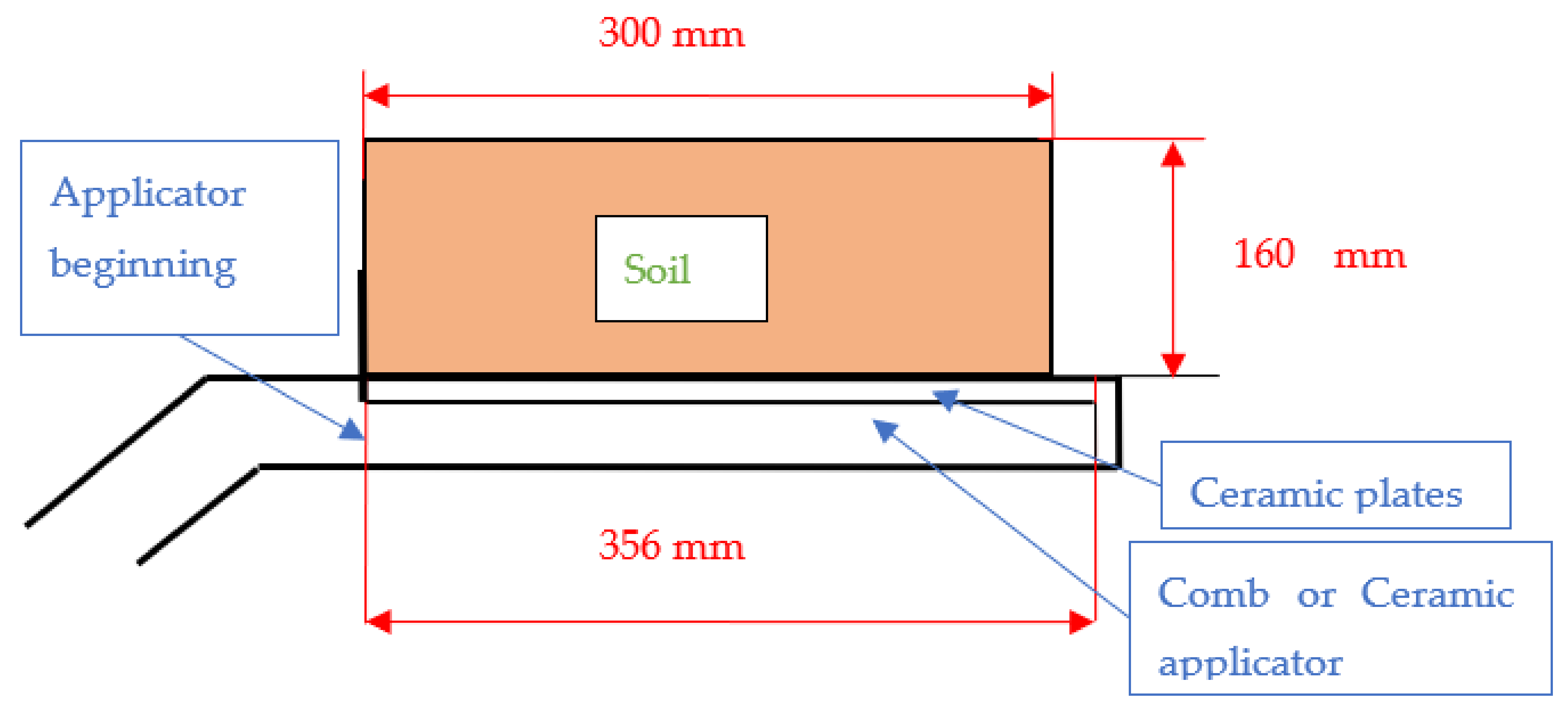
A 30 kW (2.45 GHz) microwave generator was used for the experiments (Figure 3). The applicators were connected to the microwave generator, during separate experimental runs, by waveguides and placed in a metal box having dimensions of 400 mm × 500 mm × 1120 mm for leakage protection. The soil was placed in polypropylene containers with dimensions of 120 mm × 250 mm × 300 mm. The container, with soil, was positioned on the applicator, as shown in Figure 3b. An auto tuner was used in the microwave system to provide good impedance matching of the generator and applicators (with the soil) to practically remove power reflection in the system.
Temperatures in the soil were measured using a digital thermometer (QM1601 with a temperature range of 0 to 1000 °C ± 0.5%, Digitech Pty Ltd., Clyde North, VIC, Australia) and type K thermocouples (Evolution Sensors and Control, Inc., Mullica Hill, NJ, USA), after the microwave heating was completed. These measurements were made at 10, 30, 50, 80, 100 and 140 mm above the applicator (as per the arrangement in Figure 4) along the length of the applicators, at distances of 30, 60, 90, 120, 150, 180, 210, 240, 270 and 350 mm from the beginning of the applicators, and across the applicators, in both directions, at distances of 0, 37.5, 75 and 112.5 mm from the centre plane of the applicators. The distribution of the measuring points covered the whole volume of the soil along, across, and above the applicator in the soil samples (i.e., 420 temperature measurements per experimental replicate). A lay-on jig was used for locating the thermocouple positioning during temperature measurements. To obtain reliable results for microwave heating at every soil moisture content, four replicates of each heating experiment were performed for each applicator and for each soil moisture content (i.e., twenty-four separate heating experiments).
The microwave power was set to 3.5 kW, which was applied to the soil for 15 s. After heating, the temperatures were measured using the thermocouples. The energy applied to the soil during the experiments was 52.5 kJ.

4. Results

This experiment considered two variants of microwave applicators that create evanescent fields to achieve shallow heating; therefore, the soil heating patterns of each applicator are considered separately and then compared with one another. Based on the conservation of energy in thermodynamics and its extension to electromagnetic energy [45], we assume that the temperature distribution in the soil represents the energy released in different parts of the soil volume and allows an assessment of the energy distribution from the microwave applicators.

4.1. Temperature Distribution in the Soil by the Comb Slow-Wave Applicator (2.45 GHz)

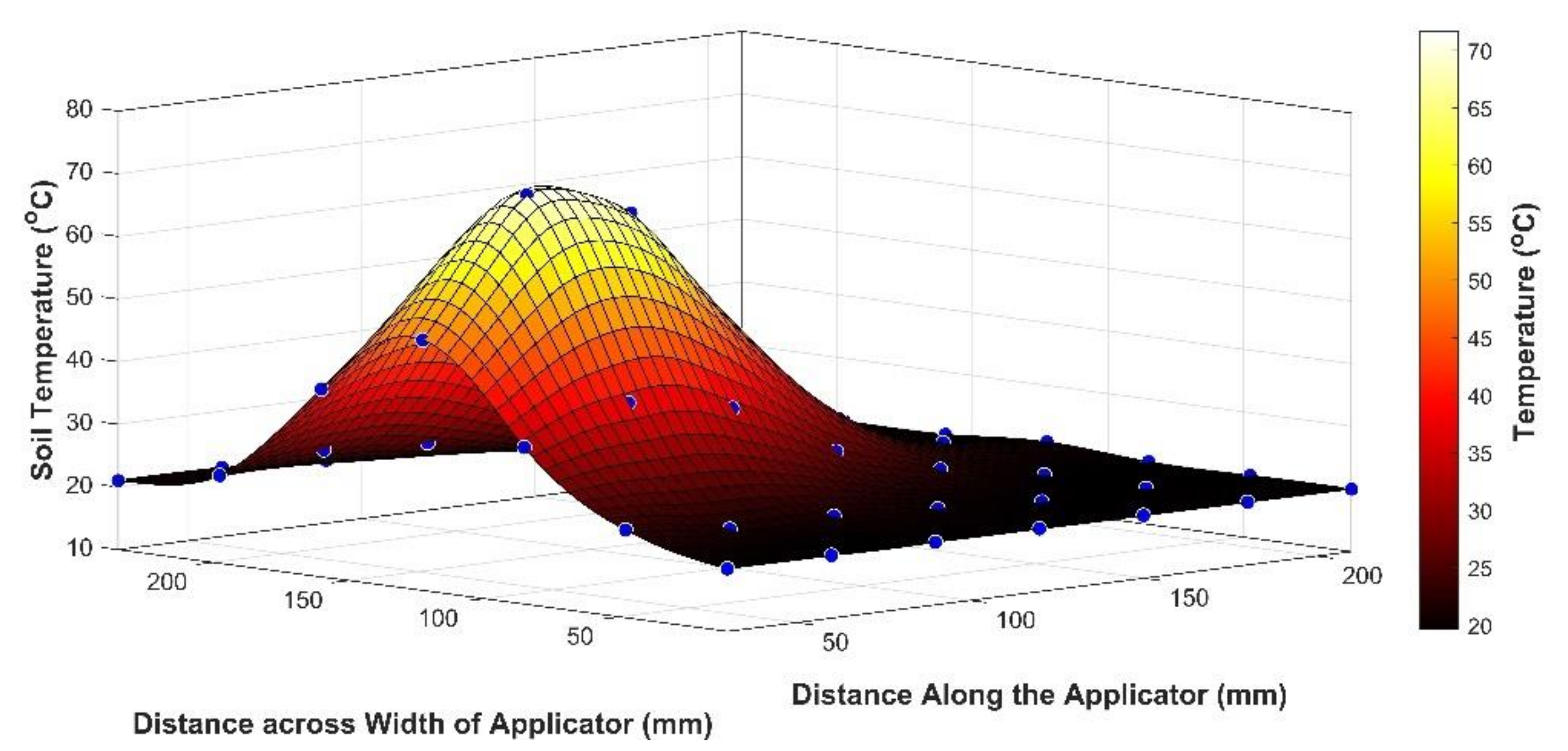
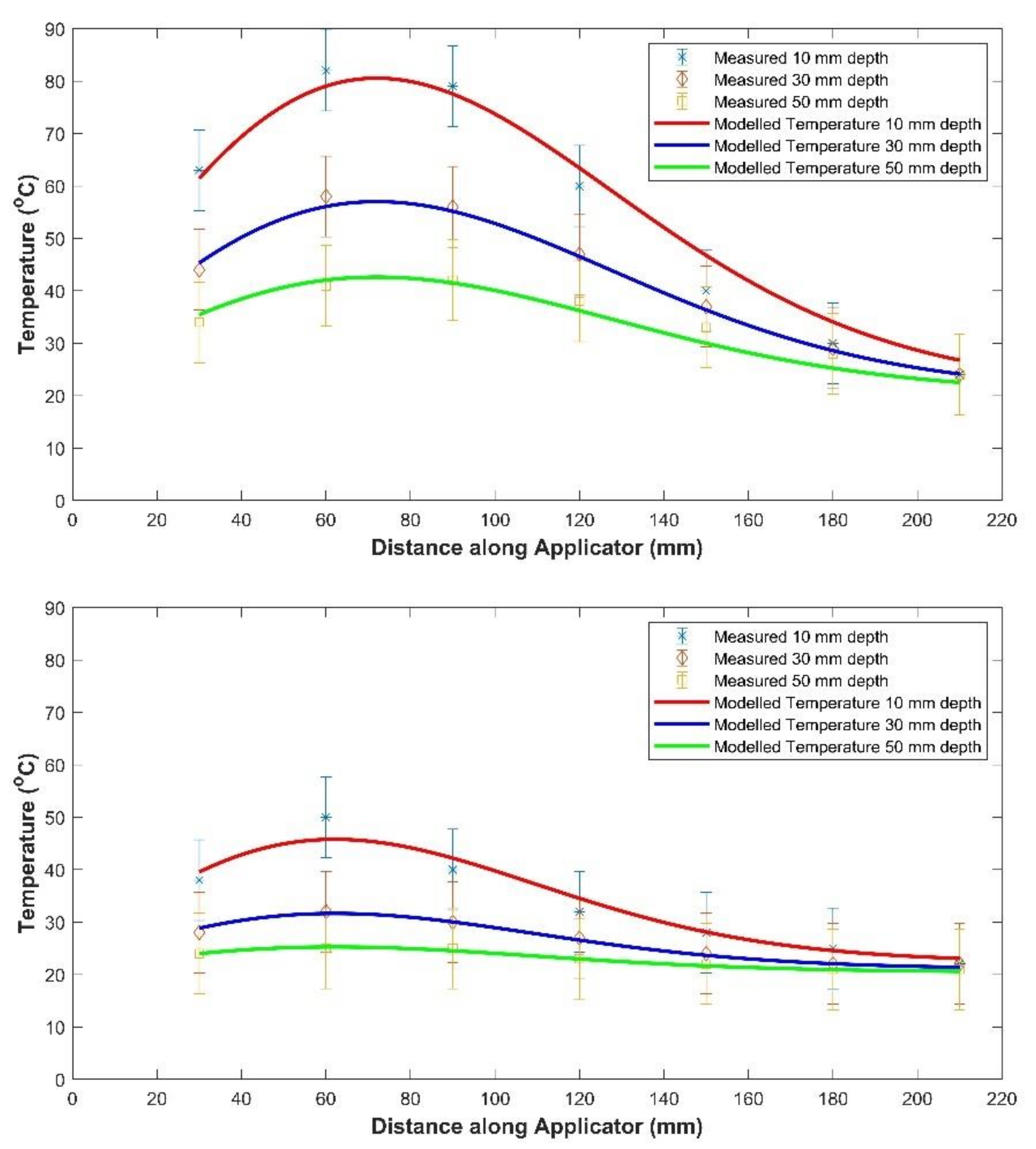
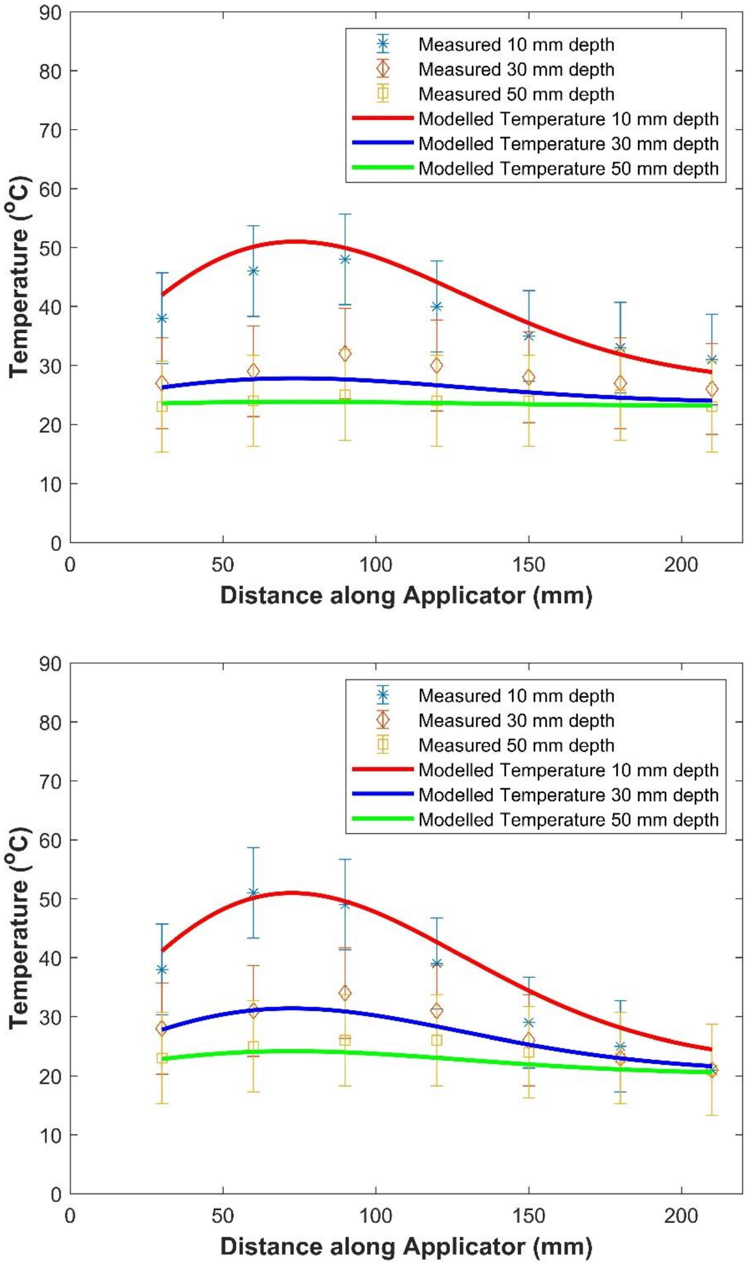
Figure 5 shows a typical temperature distribution in the soil at a depth of 10 mm, due to the comb slow-wave applicator, after applying 3.5 kW of microwave power for 15 s. The temperature distribution in the soil, along the vertical central plane of the comb slow-wave applicator, for MC = 32% and 174%, is shown in Figure 6. Most of the energy is absorbed in the central vertical plane within the top 50 mm of soil. The location of maximum energy absorption is about 60 mm from the beginning of the applicator. Almost all of the energy was absorbed within 200 mm from the start of the applicator irrespective of soil moisture content. The mathematical model for temperature distribution, developed earlier, provides a reasonable estimate of the temperature distribution in the soil after heating with the comb slow-wave applicator (R2 = 0.79). The key soil parameters of the model for soil temperature, for the comb slow-wave experiments, are shown in Table 2.

4.2. Temperature Distribution in the Soil by Ceramic Applicator (2.45 GHz)

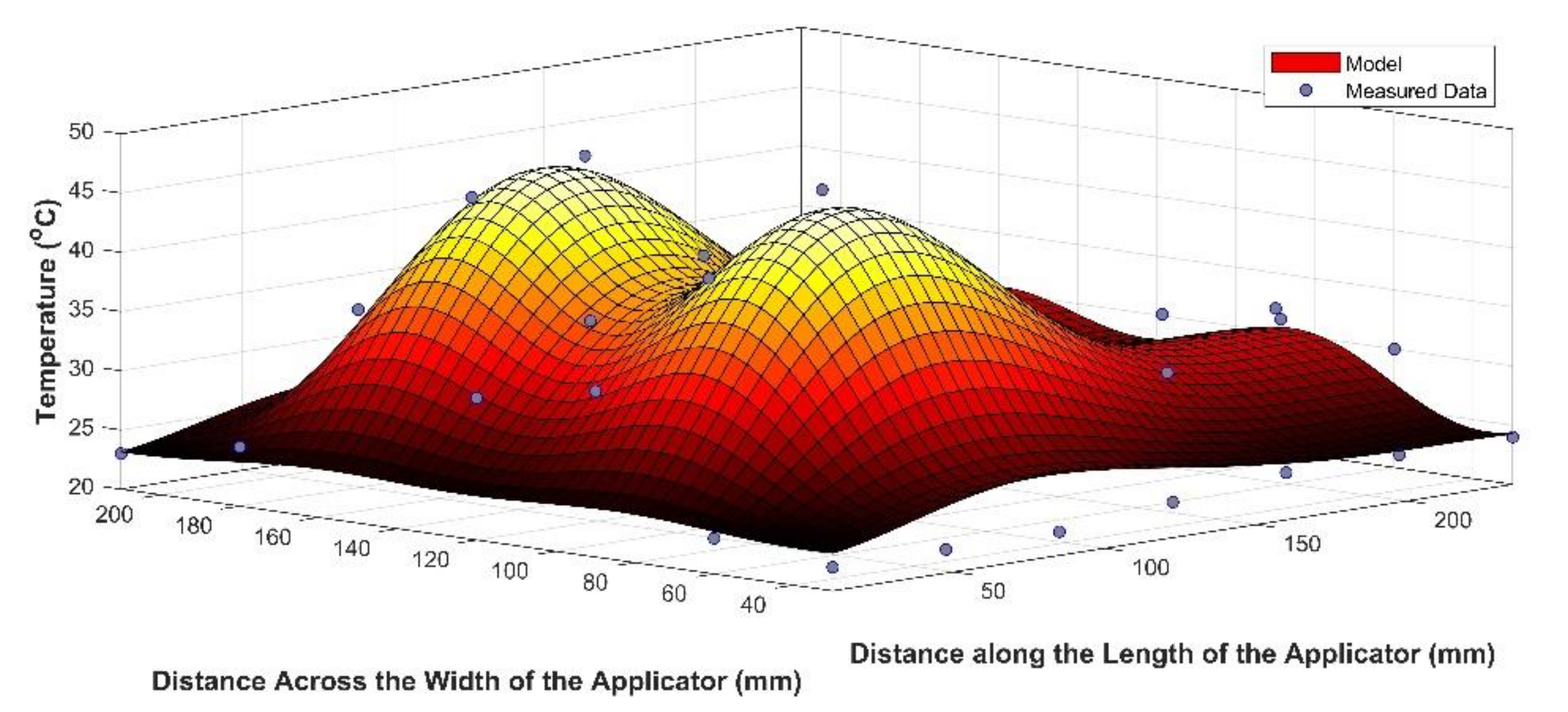
Figure 7 shows a typical temperature distribution in the soil, at a depth 10 mm below the FTIR ceramic applicator, after applying 3.5 kW of microwave power for 15 s. The ceramic block, with the 3 mm ceramic plates on the top, forms a ceramic applicator with a thickness of 16 mm of alumina (99%). Alumina has the following dielectric parameters: DC = 9.8, loss tangent 0.0002. When microwaves travel through the alumina, their wave length is shortened.
The wave length in any material (ceramics) is given by:
λ = λ o κ
In our case, at 2.45 GHz, the wave length is 122 mm in air and 40 mm in the ceramic medium (k’ = 9.8). This means that multiple modes will be manifested inside the ceramic block, with one or more of these modes becoming dominant. In this case, the microwave fields in the ceramic provide two energy maximums across the applicator (Figure 7). Note that the comb applicator provides only one maximum across the width of the applicator, because the wave length in the air that fills the teeth in the comb is 122 mm.
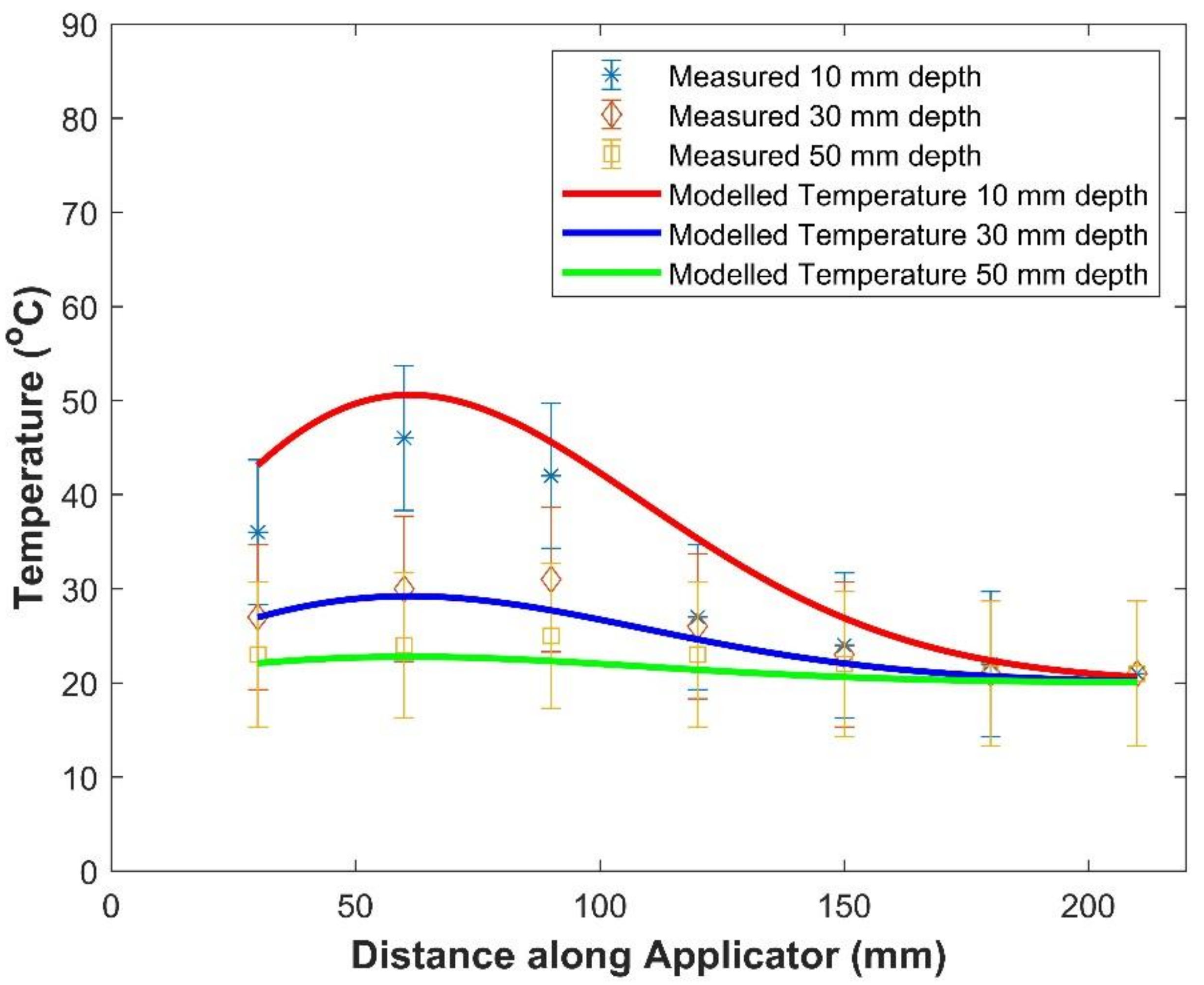
The temperature distribution along the ceramic applicator, in the peak heating lobe, is shown in Figure 8. The key soil parameters used in the modelling of soil temperature for the FTIR experiments are shown in Table 3.

5. Discussion

Both microwave applicators create evanescent microwave fields, which result in shallow soil heating. This is consistent with studies by Pchelnikov [23], who shows that the comb slow-wave structures are often used for heating thin materials. The ceramic FTIR applicator provides better energy distribution uniformity and heating consistency over the horizontal footprint of the applicator, compared with the comb slow-wave applicator. The better distribution of energy is linked to the multi-modal resonance within the dielectric slab. This is consistent with the field equations presented by Meredith [46]. Soil moisture has less effect on the soil heating profile of the FTIR applicator than in the case of the comb slow-wave applicator.
As with all modelling, the equations for temperature distributions (Equations (5) and (12)) assume homogeneous properties for the soil and the ceramic elements in the applicator and consistency of the microwave source in terms of both frequency and power delivery. Local inhomogeneity of these materials and inconsistency of the microwave system during the experiment results in variation in the measured temperature from the predicted temperatures. Instrument uncertainty and measurement error will also contribute to some variation in the experimentally determined temperatures from the model predictions. It is noted, however, that the modelled temperatures lie within the bounds of measurement uncertainty, as indicated by the error bars shown in Figure 6 and Figure 8.
The natural attenuation of the microwave fields in these soils varies between 1.3 and 3.4 m−1, depending on the soil moisture, with dry soils having a lower attenuation compared with moist soils. Microwave attenuation has been used to measure moisture in grain samples [47], so the relationship between soil moisture and microwave attenuation is expected. The evanescent field attenuation is many times higher than natural attenuation. In the case of the comb slow-wave applicator, the evanescent field decay parameter τ varies from 17.6 in dry soil to 19.9 in very moist soil. This is consistent with the mathematical models presented earlier and with other mathematical models from the literature [48]. These attenuation factors are 9.5 and 5.9 times higher than the natural soil attenuation in the cases of dry and wet soil, respectively. It is also interesting that the evanescent field attenuation increases as the soil moisture increases.
By comparison, the evanescent field decay parameter τ for the FTIR applicator varies from 44.0 in dry soil to 30.0 in very moist soil. These attenuation factors are 34 and 8.8 times higher than natural soil attenuation in the cases of dry and wet soil, respectively. It is also interesting that the evanescent field attenuation associated with the FTIR applicator decreases as the soil moisture increases, which is opposite to the comb slow-wave’s behaviour. This paper seems to be the first time that an FTIR applicator has been used for heating; therefore, it is not possible to compare these results with other literature. However, the inverse response of the evanescent field decay parameter with soil dielectric properties (i.e., increasing moisture content increases the dielectric properties of soil [49]) appears to be inherent in the mathematical models for the heat generated by these applicators (i.e., in Equations (3) and (9)).
The width of the heating pattern is wider for the FTIR applicator compared with the comb slow-wave applicator; however, the peak temperature generated by the comb slow-wave applicator is 18% higher than that of the FTIR applicator (Figure 9).
The thermal energy in an elemental volume of soil is given by [50]:
E v = ρ C p T v · dv + L water · dm w
The initial and final mass of the soil samples, before and after heating, was not recorded; therefore, ignoring the latent heat of water vaporisation, the thermal energy deposited into the soil samples by each applicator can be estimated by integrating their respective temperature distributions over the volume of influence and multiplying by the soil density and thermal capacity of the soils.
Therefore, for the comb slow-wave applicator:
E T = ρ C p n ω ε o κ E o 2 8 χ α 2 e 4 γ α 2 t 1 x = 0 y = 0 A z = 0 L e 2 τ x · sin 2 π qy A · e 2 α z + h k + 2 α · z · e z 2 4 γ t · dx · dy · dz
Or
E T = ρ C p n ω ε o κ E o 2 8 χ α 2 e 4 γ α 2 t 1 A 4 τ 1 2 α 1 e 2 α L 2 γ ht + 4 α γ kt k 1 e L 2 4 γ t
The thermal energy deposited by the FTIR applicator is:
E T = ρ C p n ω ε o κ E o 2 8 χ α 2 e 4 γ α 2 t 1 x = 0 y = 0 A z = 0 L e 2 τ x · sin 2 π qy A · sin 2 π mz L · e 2 α z · dx · dy · dz
Or
E T = ρ C p n ω ε o κ E o 2 8 χ α 2 e 4 γ α 2 t 1 A 4 τ 2 α 2 4 π m L 2 + 4 α 2 e 2 α L 1 + 1 4 α 1 e 2 α L
Based on experimentally determined parameters and published soil data [42], the average estimated thermal energy in the soil, after heating with the comb slow-wave applicator, was 42.9 kJ for the dry soil and 47.7 kJ for the wet soil. Therefore, the estimated efficiency of the comb slow-wave applicator was 0.82 and 0.91, respectively. The average estimated thermal energy in the soil, after heating with the FTIR applicator, was 41.1 kJ for the dry soil and 35.5 kJ for the wet soil. Therefore, the estimated efficiency of the FTIR applicator was 0.78 and 0.68, respectively.
The thermal properties of the soils that were used on the current experiments were not directly measured. Published data for soils [42] were used instead of experimentally determined thermal properties for the soil that was used in this experiment. Moreover, the experimental protocol did not include an evaluation of the moisture loss due to evaporation during the microwave heating; therefore, accounting for all the energy released in the soil was not possible. Because of these two limitations, the efficiency estimates presented here are indicative only.
Equation (15) can be modified to reveal the energy dissipated in the soil between the surface and a predetermined depth into the soil. The resulting energy dissipation is given by:
E d = E d 1 e 2 τ d
Using Equation (19), over 70% of the heating from the comb slow-wave applicator occurs within the first 50 mm of dry soil. In moist soil, over 86% of the heating occurs in the top 50 mm of soil. In the case of the FTIR application, over 95% of the heating occurs in the first 50 mm of moist soil and almost 99% of the heating occurs in the top 50 mm of dry soil.
Soil texture (the percentages of sand, silt, clay and organic matter in the soil) affects the dielectric properties of the soil, and affects the moisture holding capacity, thermal properties [51], and dielectric properties of soils [6,52,53]; therefore, these applicators need to be further tested in different soil types to determine their efficacy in a broader range of soil types. The microwave heating rate is also directly related to applied microwave power; therefore, the applicators need to be tested using higher input power to verify their efficacy and determine their ability to operate without generating plasma. Microwave generated plasma can reach temperatures over 1000 K [54], which can be a fire hazard in dry field conditions; therefore, future high power testing is an important step in the path towards commercialisation of the technology.
Scaling up this technology for field applications can be achieved using multiple applicators, of the same design, arranged in a one- or two-dimensional array, like the tines on a plough. If the applicators provide some overlap in their coverage as the array is drawn forward using a prime mover, such as a tractor, complete coverage of a wide swath can be achieved. Each applicator can be fed from an individual microwave source, or by using power splitting from a single large microwave source. The static tests performed in this experiment provide some indication of the dynamic performance of the applicators as they are drawn over the surface of the soil; however, future experimental work needs to confirm the temperature distribution under dynamic conditions. Designs, based on multiple applicator arrays, have been developed and fabricated. These systems are currently undergoing extensive dynamic field trials and will be reported on in a future paper.

6. Conclusions

Both microwave applicators restrict most of the microwave heating to a depth of 50 mm, as they were designed to do. The comb slow-wave applicator heats a larger volume of soil (i.e., more heating occurs at greater depths) in dry soils than in moist soils. The FTIR applicator dissipates almost all of its microwave energy, manifested as soil heating, in the top 50 mm of soil. The FTIR applicator is less affected by soil moisture and has a wider heating pattern than the comb slow-wave applicator. The evanescent field attenuation associated with the FTIR applicator decreases as the soil moisture increases, which is opposite to the comb slow-wave’s behaviour.
This paper contributes to the growing evidence that evanescent fields can be generated using comb slow-wave and FTIR structures and can be used to generate shallow heating in deep materials, such as soils. This experiment was a static test of the heating performance of these applicators; thus, dynamic testing, with the applicator in motion relative to the soil, is required. Field experiments also need to be completed to determine whether the technology can be developed further into a commercial prospect for agricultural and environmental weed control.

7. Patents

This work has been patented under Brodie, et al. [55].

Author Contributions

Conceptualization, G.B. and G.T.; methodology, G.T.; formal analysis, G.B.; investigation, G.T.; resources, G.B.; data curation, G.B.; writing—original draft preparation, G.T. and G.B.; writing—review and editing, G.B.; visualization, G.B.; supervision, G.T.; project administration, G.B.; funding acquisition, G.B. All authors have read and agreed to the published version of the manuscript.

Funding

This research was funded by the Australian Grains Research and Development Corporation, under grant number UM00053.

Data Availability Statement

Data can be requested from the corresponding author.

Conflicts of Interest

The authors declare no conflict of interest. The funders had no role in the design of the study; in the collection, analyses, or interpretation of data; in the writing of the manuscript, or in the decision to publish the results.

Nomenclature

SymbolDescription
AqAmplitude of qth resonant wave across the width of the FTIR dielectric resonator
AsWidth of the applicator in the y-direction (m)
BlAmplitude of lth resonant wave in the height of the FTIR dielectric resonator
cSpeed of light in a vacuum (m s−1)
CmAmplitude of mth resonant wave along the length of the FTIR dielectric resonator
CpThermal capacity of the soil (J kg−1 °C−1)
DCDielectric constant of a material
dDepth of the comb teeth (m)
EoField amplitude (V m−1)
EdThermal energy deposited into the soil during microwave heating between the soil surface and a known depth d metres into the soil (J)
EtThermal energy deposited into the soil during microwave heating (J)
fFrequency (Hz)
hCoefficient of convective heat transfer at the surface of the dielectric material (W m−2 K−1)
kWave number of the microwave fields in the free space between the teeth of the comb slow-wave structure (m−1)
LLength of the applicator (m)
LwaterLatent heat of vaporisation for water (J kg−1)
MCMoisture content of the soil (on a dry weight basis)
nIn Equations (3) and (10) is the scaling factor, which accounts for simultaneous heat and moisture movement in heated material [28]
n1Refractive index of dielectric block inside resonant cavity
n2Refractive index of dielectric material adjacent to FTIR applicator dieelctric block
q, l and mMode numbers for the electromagnetic field in a resonant cavity
ToThe initial temperature of the dielectric material (°C)
λₒWavelength in vacuum or in air (m)
TPeriod of the comb slow-wave teeth (m)
αWave attenuation factor in the soil (m−1)
βPhase velocity (m s−1)
εoElectrical permittivity of free space
γThermal diffusivity of the dielectric material (m2 s−1) Note: γ = χ ρ C p
κ’Dielectric constant of the space adjacent to the Comb slow-wave structure
κ”Dielectric loss factor of the dielectric material
λWavelength of the electromagnetic fields (m)
ρSoil density (kg m−3)
τEvanescent field decay rate for the comb slow-wave or FTIR structure (m−1)
τ2Evanescent field decay rate in soil for the comb slow-wave structure, when the comb is covered by a dielectric material (m−1)
ωAngular frequency (Rad s−1)
θAngle of incidence of an electromagnetic wave encountering a boundary of a dielectric material, measured relative to the normal of the surface of the dielectric block, for the FTIR electromagnetic field (Radians)
χThermal conductivity of the dielectric material (W m−1 K−1)
x ^ Unit vector perpendicular to the surface of the comb
z ^ Unit vector along the surface of the comb in the direction of field propagation

References

  1. Velazquez-Marti, B.; Gracia-Lopez, C.; Marzal-Domenech, A. Germination Inhibition of Undesirable Seed in the Soil using Microwave Radiation. Biosyst. Eng. 2006, 93, 365–373. [Google Scholar] [CrossRef]
  2. Davis, F.S.; Wayland, J.R.; Merkle, M.G. Ultrahigh-Frequency Electromagnetic Fields for Weed Control: Phytotoxicity and Selectivity. Science 1971, 173, 535–537. [Google Scholar] [CrossRef] [PubMed]
  3. Davis, F.S.; Wayland, J.R.; Merkle, M.G. Phytotoxicity of a UHF Electromagnetic Field. Nature 1973, 241, 291–292. [Google Scholar] [CrossRef]
  4. Wayland, J.R.; Davis, F.S.; Merkle, M.G. Vegetation Control. U.S. Patent Office 4092800, 30 July 1978. [Google Scholar]
  5. Wayland, J.; Merkle, M.; Davis, F.; Menges, R.M.; Robinson, R. Control of weeds with UHF electromagnetic fields. Weed Res. 1975, 15, 1–5. [Google Scholar] [CrossRef]
  6. Falciglia, P.P.; Vagliasindi, F.G.A. Techno-economic analysis of hydrocarbon-polluted soil treatment by using ex situ microwave heating: Influence of soil texture and soil moisture on electric field penetration, operating conditions and energy costs. J. Soils Sediments 2016, 16, 1330–1344. [Google Scholar] [CrossRef]
  7. Barker, A.V.; Craker, L.E. Inhibition of Weed Seed Germination by Microwaves. Agron. J. 1991, 83, 302–305. [Google Scholar] [CrossRef]
  8. Diprose, M.F.; Benson, F.A.; Willis, A.J. The Effect of Externally Applied Electrostatic Fields, Microwave Radiation and Electric Currents on Plants and Other Organisms, with Special Reference to Weed Control. Bot. Rev. 1984, 50, 171–223. [Google Scholar] [CrossRef]
  9. Khan, M.J.; Jurburg, S.D.; He, J.; Brodie, G.; Gupta, D. Impact of microwave disinfestation treatments on the bacterial communities of no-till agricultural soils. Eur. J. Soil Sci. 2019, 71, 1006–1017. [Google Scholar] [CrossRef]
  10. Mahdi, W.M.; Al-Badri, K.S.L.; Al-Samarrai, G.F. Use of Microwave Radiation in Soil Sterilization and Effects on the Bacteria, Fungi and Growth Characteristics of Chickpea Plant (Cicer arietinum L.). Plant Arch. 2019, 19, 2064–2069. [Google Scholar]
  11. Brodie, G.; Khan, M.J.; Gupta, D. Microwave Soil Treatment and Plant Growth. In Sustainable Crop Production; Filho, M.C.M.T., Hasanuzzaman, M., Eds.; IntechOpen: London, UK, 2019. [Google Scholar] [CrossRef] [Green Version]
  12. Mahdi, W.M.; Al-Badri, K.S.L.; Alqaisi, M.R.M. Effect of Microwave Radiation on Bacteria, Fungi and Some Growth Characteristics of Cowpea Vigna unguiculata L. Gesunde Pflanzen 2020, 73, 161–167. [Google Scholar] [CrossRef]
  13. Metaxas, A.C.; Meredith, R.J. Industrial Microwave Heating; Peter Peregrinus: London, UK, 1983. [Google Scholar]
  14. Shibakova, V.S. On the possibility of using microwave energy for soil stabilization. Bull. Int. Assoc. Eng. Geol. 1975, 12, 89–91. [Google Scholar] [CrossRef]
  15. De Wilde, M.; Buisson, E.; Yavercovski, N.; Willm, L.; Bieder, L.; Mesléard, F. Using Microwave Soil Heating to Inhibit Invasive Species Seed Germination. Invasive Plant Sci. Manag. 2017, 10, 262–270. [Google Scholar] [CrossRef] [Green Version]
  16. Tongsheng, S. Directivity factor of coupled antennas for microwave heating of asphalt mixture. Int. J. Appl. Electromagn. Mech. 2016, 50, 647–663. [Google Scholar] [CrossRef]
  17. Mavrogianopoulos, G.N.; Frangoudakis, A.; Pandelakis, J. Energy Efficient Soil Disinfestation by Microwaves. J. Agric. Eng. Res. 2000, 75, 149–153. [Google Scholar] [CrossRef]
  18. Cooper, A.P.; Brodie, G. The effect of microwave radiation and soil depth on soil pH, N, P, K, SO4 and bacterial colonies. Plant Prot. Q. 2009, 24, 67–70. [Google Scholar]
  19. Chauhan, B.S.; Gill, G.; Preston, C. Influence of tillage systems on vertical distribution, seedling recruitment and persistence of rigid ryegrass (Lolium rigidum) seed bank. Weed Sci. 2006, 54, 669–676. [Google Scholar] [CrossRef]
  20. Sinclair, K.I.; Goussetis, G.; Desmulliez, M.P.Y.; Sangster, A.J.; Tilford, T.; Bailey, C.; Parrott, A.K. Optimization of an Open-Ended Microwave Oven for Microelectronics Packaging. IEEE Trans. Microw. Theory Tech. 2008, 56, 2635–2641. [Google Scholar] [CrossRef]
  21. Cronin, N.J. Microwave and Optical Waveguides; J W Arrowsmith Ltd.: Bristol, UK, 1995. [Google Scholar]
  22. Dunn, D.A. Slow wave couplers for microwave dielectric heating systems. J. Microw. Power 1967, 2, 7–20. [Google Scholar] [CrossRef]
  23. Pchelnikov, Y.N. Features of slow waves and potentials for their nontraditional application. Appl. Radiotech. Electron. Bioligy Med. 2003, 48, 450–462. [Google Scholar]
  24. Pchelnikov, Y.N.; Yelizarov, A.A. Medical application of slow electromagnetic waves. In Proceedings of the Electronics and Radiophysics of Ultra-High Frequencies, Saint Petersburg, Russia, 24–28 May 1999; pp. 464–467. [Google Scholar]
  25. Chen, F.S. The Comb-Type Slow-Wave Structure for TWM Applications. Bell Syst. Tech. J. 1964, 43, 1035–1066. [Google Scholar] [CrossRef]
  26. Pchelnikov, Y.N.; Kholodnyi, V.A. Medical application of surface electromagnetic waves. Bioelectrochem. Bioenergy 1998, 47, 283–290. [Google Scholar] [CrossRef]
  27. Brodie, G.; Pchelnikov, Y.; Torgovnikov, G. Development of Microwave Slow-Wave Comb Applicators for Soil Treatment at Frequencies 2.45 and 0.922 GHz (Theory, Design, and Experimental Study). Agriculture 2020, 10, 604. [Google Scholar] [CrossRef]
  28. Brodie, G. Simultaneous heat and moisture diffusion during microwave heating of moist wood. Appl. Eng. Agric. 2007, 23, 179–187. [Google Scholar] [CrossRef]
  29. Van Remmen, H.H.J.; Ponne, C.T.; Nijhuis, H.H.; Bartels, P.V.; Herkhof, P.J.A.M. Microwave Heating Distribution in Slabs, Spheres and Cylinders with Relation to Food Processing. J. Food Sci. 1996, 61, 1105–1113. [Google Scholar] [CrossRef]
  30. Meredith, R. Engineers’ Handbook of Industrial Microwave Heating; The Institute of Electrical Engineers: Stevenage, UK, 1998. [Google Scholar]
  31. Eremenko, Z.E. The Electromagnetic Wave Propagation on the Interface between Low and High Loss Dielectrics. Adv. Condens. Matter Phys. 2010, 2010, 683521. [Google Scholar] [CrossRef] [Green Version]
  32. Khattak, H.K.; Bianucci, P.; Slepkov, A.D. Linking plasma formation in grapes to microwave resonances of aqueous dimers. Proc. Natl. Acad. Sci. USA 2019, 116, 4000–4005. [Google Scholar] [CrossRef] [Green Version]
  33. Han, J.Y.; Kollin, J.S.; Slobodin, D.E. Touch Sensing with Frustrated Total Internal Reflection. U.S. Patent 8,736,581, 27 May 2014. [Google Scholar]
  34. Niederauer, C.; Blumhardt, P.; Mücksch, J.; Heymann, M.; Lambacher, A.; Schwille, P. Direct characterization of the evanescent field in objective-type total internal reflection fluorescence microscopy. Opt. Express 2018, 26, 20492–20506. [Google Scholar] [CrossRef] [Green Version]
  35. Taheri, S.; Brodie, G.; Jacob, M.V.; Antunes, E. Dielectric properties of chickpea, red and green lentil in the microwave frequency range as a function of temperature and moisture content. J. Microw. Power Electromagn. Energy 2018, 52, 198–214. [Google Scholar] [CrossRef]
  36. Sipahioglu, O.; Barringer, S.A. Dielectric properties of vegetables and fruits as a function of temperature, ash, and moisture content. J. Food Sci. 2003, 68, 234–239. [Google Scholar] [CrossRef]
  37. Mironov, V.; Savin, I. A temperature-dependent multi-relaxation spectroscopic dielectric model for thawed and frozen organic soil at 0.05–15 GHz. Phys. Chem. Earth Parts A/B/C 2015, 83, 57–64. [Google Scholar] [CrossRef]
  38. Kabir, M.F.; Daud, W.M.; Khalid, K.B.; Sidek, H.A.A. Temperature dependence of the dielectric properties of rubber wood. Wood Fiber Sci. 2001, 33, 233–238. [Google Scholar]
  39. Brodie, G. Modeling the very broad band dielectric properties of water. J. Microw. Power Electromagn. Energy 2021, 55, 80–89. [Google Scholar] [CrossRef]
  40. Yee, K.S. Numerical solution of initial boundary value problems involving Maxwell’s equations in isotropic media. IEEE Trans. Antennas Propag. 1966, 14, 302–307. [Google Scholar]
  41. Israelsen, O.W.; West, F.L. Water Holding Capacity of Irrigated Soils; Utah Agricultural College: Logan, UT, USA, 1922; pp. 1–24. [Google Scholar]
  42. Oyeyemia, K.D.; Sanuade, O.A.; Oladunjoye, M.A.; Aizebeokhai, A.P.; Olaojo, A.A.; Fatoba, J.O.; Olofinnade, O.M.; Ayara, W.A.; Oladapo, O. Data on the thermal properties of soil and its moisture content. Data Brief 2018, 17, 900–906. [Google Scholar] [CrossRef]
  43. Richards, L.A.; Weaver, L.R. Moisture retention by some irrigated soils as related to soil moisture tension. J. Agric. Res. 1944, 69, 215–235. [Google Scholar]
  44. Kabir, H.; Khan, M.J.; Brodie, G.; Gupta, D.; Pang, A.; Jacob, M.V.; Antunes, E. Measurement and modelling of soil dielectric properties as a function of soil class and moisture content. J. Microw. Power Electromagn. Energy 2020, 54, 3–18. [Google Scholar] [CrossRef]
  45. Abdelh, S. An Advanced Review of Thermodynamics of Electromagnetism. Int. J. Res. Stud. Sci. Eng. Technol. 2016, 3, 10–25. [Google Scholar]
  46. Meredith, R.J. A three axis model of the mode structure of multimode cavities. J. Microw. Power Electromagn. Energy 1994, 29, 31–44. [Google Scholar] [CrossRef]
  47. Trabelsi, S.; Nelson, S.O. Microwave moisture meter for granular and particulate materials. Proceedings of Instrumentation and Measurement Technology Conference (I2MTC), Austin, TX, USA, 3–6 May 2010; pp. 1304–1308. [Google Scholar]
  48. Verbitskii, I.L. Dispersion-relations for comb-type slow-wave structures. IEEE Trans. Microw. Theory Tech. 1980, 28, 48–50. [Google Scholar] [CrossRef]
  49. Curtis, J.O. Moisture Effects on the Dielectric Properties of Soils. IEEE Trans. Geosci. Remote Sens. 2001, 39, 125–128. [Google Scholar] [CrossRef]
  50. Holman, J.P. Heat Transfer, 10th ed.; McGraw-Hill: New York, NY, USA, 1997. [Google Scholar]
  51. Nidal, H.A.-H. Thermal Properties of Soils as affected by Density and Water Content. Biosyst. Eng. 2003, 86, 97–102. [Google Scholar] [CrossRef]
  52. Velázquez-Martí, B.; Gracia-López, C.; Plaza-Gonzalez, P.J. Determination of Dielectric Properties of Agricultural Soil. Biosyst. Eng. 2005, 91, 119–125. [Google Scholar] [CrossRef]
  53. Dobson, M.C.; Ulaby, F.T.; Hallikainen, M.T.; El-rayes, M.A. Microwave Dielectric Behavior of Wet Soil-Part II: Dielectric Mixing Models. IEEE Trans. Geosci. Remote Sens. 1985, GE-23, 35–46. [Google Scholar] [CrossRef]
  54. Al-Shamma’a, A.I.; Wylie, S.R.; Lucas, J.; Pau, C.F. Design and construction of a 2.45 GHz waveguide-based microwave plasma jet at atmospheric pressure for material processing. J. Phys. D Appl. Phys. 2001, 34, 2734–2741. [Google Scholar] [CrossRef]
  55. Brodie, G.; Torkovnikov, G.; Farrell, P. Microwave Application Method and Apparatus. AU Patent 2016905272, 20 December 2016. [Google Scholar]
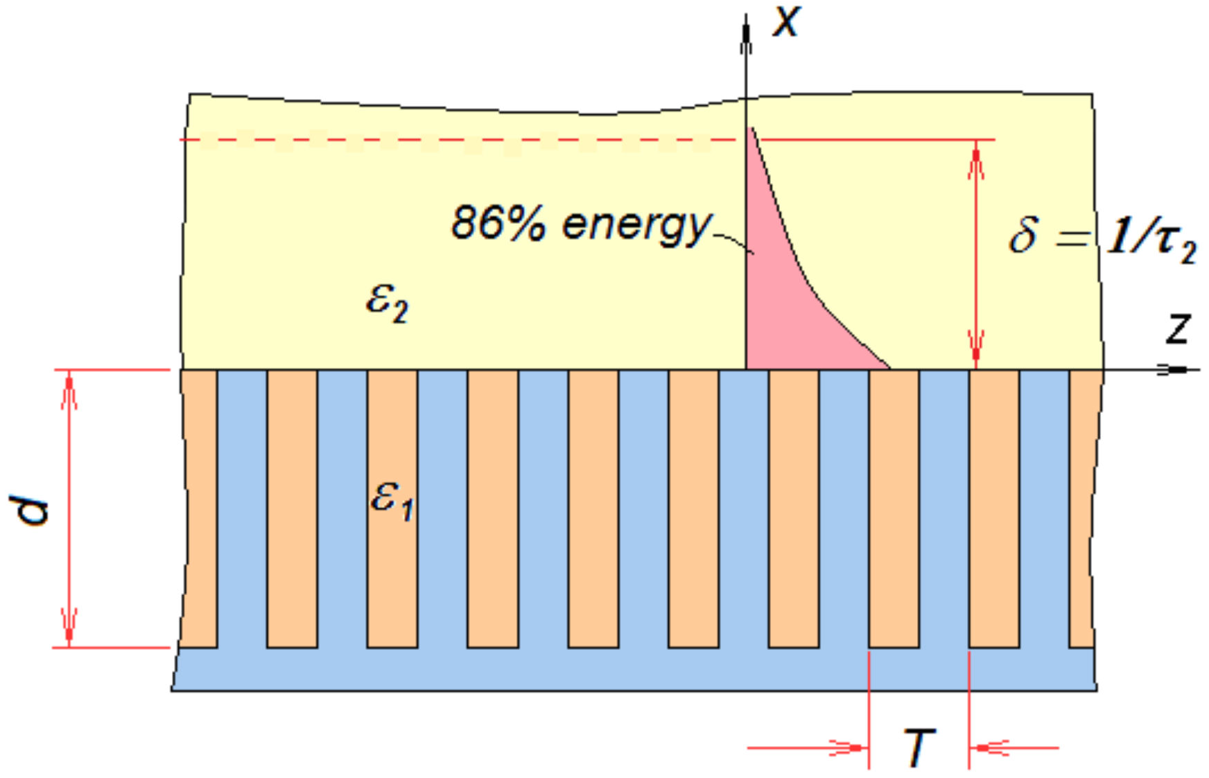
Figure 1. Geometry of a metal comb-like slow-wave structure.
Energies 15 01068 g001
Figure 2. Comb applicator (left) and ceramic applicator (middle) without ceramic plates, applicator covered with ceramic plates 3 mm × 84 mm × 146 mm—4 pieces (right).
Energies 15 01068 g002
Figure 3. (a) Applicator (inside of metal box) connected to a 30 kW MW generator, operating at 2.45 GHz and (b) showing the soil sample set up on the applicator inside a metal box, which prevented stray radiation of microwave energy.
Energies 15 01068 g003
Figure 4. Schematic of applicator with soil in container.
Energies 15 01068 g004
Figure 5. Temperature distribution in the soil at 10 mm depth produced by the comb slow-wave applicator (F = 2.45 GHz, p = 3.5 kW, time of MW heating 15 s, To = 20 °C, applied energy 52.5 kJ. Soil moisture content MC = 89%, density = 710 kg m−3).
Energies 15 01068 g005
Figure 6. Temperature distribution in the soil along the comb slow-wave applicator’s central plane at F = 2.45 GHz, p = 3.5 kW, time of MW heating = 15 s, To = 20 °C, applied energy 53 kJ. Top graph–MC = 32%, density = 586 kg m−3, bottom graph–MC = 174%, density = 1070 kg m−3. (Error bars represent the standard error of the data).
Energies 15 01068 g006
Figure 7. Temperature distribution in the soil on the depth 10 mm by ceramic applicator after MW heating at F = 2.45 GHz, p = 3.5 kW, time of MW heating 15 s, To = 23 °C, applied energy 53 kJ. Soil moisture content 89%, density 710 kg m−3.
Energies 15 01068 g007
Figure 8. Temperature distribution along the ceramic applicator in the peak heating lobe of the vertical plane (38 mm from the central plane) at the different depths after MW heating of soil with moisture contents of (top) 32, (middle) 89 and (bottom) 174%. (F = 2.45 GHz, p = 3.5 kW, time of MW heating—15 s, To = 23 °C, applied energy 53 kJ).
Energies 15 01068 g008aEnergies 15 01068 g008b
Figure 9. Comparison of the transverse heating profile of the comb slow-wave and FTIR applicator at 30 mm from the start of the applicator and 10 mm depth in the soil.
Energies 15 01068 g009
Table 1. Applicator parameters.
ParametersFTIR Ceramic (mm)Slow-Wave Comb (mm)
Working length 356356
Applicator thickness2323
Ceramic slab thickness13
Applicator width150150
Comb electrode width 100
Ceramic slab width100
Comb electrode thickness 16
Comb electrode conic length 185
Grove depth/width 13/3
Comb tooth thickness 3
Ceramic plates covering applicators for both applicatorsAlumina (99%) ceramic plate size 3 mm × 84 mm × 146 mm (4 pieces), (DC = 9.8, loss tangent 0.0002)
Table 2. Soil parameter values used to model soil temperature during comb slow-wave experiments (Note: uncertainty values represent ± the standard error for these values).
Parameter Soil Condition (MC %)Value
α321.3 ± 0.06 m−1
1743.4 ± 0.26 m−1
τ3217.6 ± 0.7 m−1
17419.9 ± 1.5 m−1
γ321.82 ± 0.08 × 10⁻⁴ m2 s−1
1741.32 ± 0.1 × 10⁻⁴ m2 s−1
Table 3. Soil parameter values used to model soil temperature during FTIR experiments (Note: uncertainty values represent ± the standard error for these values).
Parameter Soil Condition (MC %)Value
α321.3 ± 0.06 m−1
1743.4 ± 0.26 m−1
τ3244.0 ± 0.7 m−1
17430 ± 1.2 m−1
γ321.82 ± 0.08 × 10⁻⁴ m2 s−1
1741.32 ± 0.1 × 10⁻⁴ m2 s−1
A1 0.83 ± 0.04
A2 0.0
A3 0.63 ± 0.03
C1 0.4 ± 0.016
C2 0.34 ± 0.016
Publisher’s Note: MDPI stays neutral with regard to jurisdictional claims in published maps and institutional affiliations.