Article

A General Pattern-Based Design Optimization for Asymmetric Spoke-Type Interior PM Machines

1
Department of Electrical Engineering, The Hong Kong Polytechnic University, Hong Kong 999077, China
2
Shenzhen Institutes of Advanced Technology, Chinese Academy of Sciences, Shenzhen 518055, China
3
Department of Electronic Engineering, University of York, York YO10 5DD, UK
*
Author to whom correspondence should be addressed.
Energies 2022, 15(24), 9385; https://doi.org/10.3390/en15249385
Submission received: 16 November 2022 / Revised: 1 December 2022 / Accepted: 6 December 2022 / Published: 12 December 2022

Abstract

:
A novel asymmetric spoke-type interior permanent magnet (AS-IPM) machine is proposed in this paper. It utilizes the magnetic-field-shifting (MFS) effect to improve the torque performance, which achieves a high utilization ratio of both permanent magnet (PM) torque and reluctance torque. In addition, a general pattern of rotor topologies is proposed to represent all possible machine structures. Various rotor structures can be obtained by changing the design parameters of the general pattern. A non-dominated sorting genetic algorithm II (NSGA-II) is adopted to automatically search for optimal rotor configurations. With the aid of the optimization program, an asymmetric spoke-type rotor structure with improved performance is obtained. To showcase the advantages of the proposed machine, the electromagnetic performance is compared between a conventional spoke-type interior permanent magnet (S-IPM) machine and a proposed AS-IPM machine. The finite-element simulation results show that the optimal design of the AS-IPM performs a 7.7% higher output torque ripple due to the MFS effect while the total PM volume remains the same. Meanwhile, the torque ripple of the proposed structure is significantly reduced by 82.1%.

1. Introduction

In recent years, interior permanent magnet (IPM) machines have become preferable choices for many applications due to their inherent high torque density, high efficiency, and high permanent magnet (PM) utilization ratio [1,2,3]. Several topologies have been well studied, such as bar-shaped, V-shaped, W-shaped, dual-layer V-shaped, and spoke-type IPM machines [4,5,6,7,8]. However, the torque density of IPM machines is expected to be further improved for the growing applications of electrified transportation.
Generally, the synthetic output torque of a PM synchronous machine is composed of PM torque and reluctance torque. Therefore, the torque performance can be improved by three methods, including enhancing the PM torque, improving the reluctance torque, and reducing the current angle difference between the peak values of PM torque and reluctance torque to realize an increased utilization ratio of both PM components. The third method, designated as the magnetic-field-shifting (MFS) effect, has attracted significant research attention recently. Numerous studies have been conducted to investigate the approaches to produce the MFS effect, which can be realized by the asymmetric rotor topologies [9]. The asymmetric rotor can be achieved by asymmetric rotor core topologies [10,11], asymmetric PM topologies [12,13], or both [14,15,16]. Two different asymmetric flux barriers were adopted between V-shaped magnets with different polarities in [10] and [11] to form asymmetric rotor cores. When the flux barriers were applied on the right-side cavity near the outer surface, the maximum torque was increased by 16.6%, and the torque ripple was reduced by about 18.7%. When the spoke-type flux barriers connected the inner and outer surfaces of the rotor, the torque of the proposed machine was increased by 4.6% with a 7.3% lower torque ripple. In addition, asymmetric PM structures achieved by different methods were well studied in [12,13]. The surface-inserted PMs in a hybrid-pole machine were shifted at a certain angle, while the V-shaped PMs kept the symmetric arrangement in [12]. With this special design, the angle between the PM and reluctance torque components was slightly reduced, and the average torque was improved by 4%. Another method proposed in [13] was realized by the adoption of extra ferrite magnets in the NdFeB magnets IPM machines. The two different types of magnets were assigned at each side of the V-shaped PMs to achieve the MFS effect. The proposed machine performed an 11.6% higher output torque ripple and a 6.9% lower torque ripple compared with the conventional symmetric structure. Moreover, various topologies of both asymmetric rotor core and asymmetric PMs were explored in [14,15,16]. An asymmetric rotor structure with inset PMs was proposed in [14]. This proposed machine exhibited a 14.2% torque improvement and a 37.9% torque ripple reduction. Different topologies of single-layer asymmetric V-shaped PMs with different sizes of side magnet machines were proposed in [15,16]. The output torque was increased by 8% in [15], and the torque ripple was reduced by 5.8% and 20.6% in [15] and [16], respectively. Obviously, the effectiveness of the MFS effect was verified by the torque improvement shown in the aforementioned studies. However, most proposed asymmetric machines exhibit a relatively high torque ripple, which is not applicable to industrial applications. Therefore, further study is required to achieve a high torque density and low torque ripple simultaneously.
Among various types of IPM machines, the spoke-type IPM (S-IPM) machine is one of the most popular candidates due to its simple rotor structure and great flux-focusing effect. Sufficient studies have investigated the topology and optimization of conventional S-IPM machines. The optimization of S-IPM machines has been performed according to the different situations. In [17], an S-IPM machine was optimized by allowing up to 3% irreversible demagnetization to achieve minimized PM weight. The S-IPM machine was also optimized with the consideration of FSAE autocross Germany track geometry for the FormulaStudent (FST) competition in [18]. Recently, various novel topologies of S-IPM machines have been proposed to improve torque performance, such as adding symmetrical flux barriers [19,20,21] and using asymmetric rotor design [22,23,24,25]. According to [19,20,21], both the flux barriers around the outer surface and the inner surface of the rotor made a significant contribution to the torque ripple reduction. The torque ripple was reduced by 56.3% and 58.5% in [19] and [21], respectively. The asymmetric rotor designs were realized by different methods. In [22], an asymmetric rotor with consequent-pole PMs was proposed. The average torque was increased by 2.7%, while the torque ripple was reduced by 27.8%. The asymmetric flux barriers near the outer surface of the rotor were adopted in [23,24]. In [23], the average torque was improved from 2.41 Nm to 2.62 Nm, while the torque ripple was reduced by 75.7%. Adding flux barriers is an effective way to improve machine performance, especially for asymmetric flux barriers, which combine the advantages of symmetrical flux barriers and asymmetric rotor design. The flux barriers in the V-shaped machine have been comprehensively studied in [26]. However, only the asymmetric flux barriers near the outer surface of the rotor have been investigated in the S-IPM machines. The location of flux barriers can be varied in the S-IPM machines. It can be located either around the inner circumference or near the outer surface of the rotor, or both. Hence, more possible rotor topologies with different locations of flux barriers need to be further investigated in the S-IPM machines. Moreover, the possible rotor structures by manual design are very limited. Therefore, a general expression that can represent possible spoke-type rotor structures with asymmetric flux barriers is highly expected.
This paper proposes a novel asymmetric spoke-type IPM (AS-IPM) machine, which is obtained with the assistance of a general pattern. The topologies of the conventional S-IPM machine and the proposed AS-IPM machine with flux barriers are elaborated in Section 2. Meanwhile, the MFS effect is introduced subsequently to reveal the mechanism of torque improvement. Then, the global optimization of machines is presented in Section 3, which takes the diversity of the flux barriers into consideration. To perform a fair comparison, a conventional S-IPM machine is analyzed and optimized first. Then, the stator design parameters are fixed, and the rotor topology of the AS-IPM is optimized with the assistance of the general pattern. Moreover, to showcase the improvement in the proposed structure, the performance is analyzed and compared with the conventional IPM machines in Section 4. Finally, this study is concluded in Section 5.

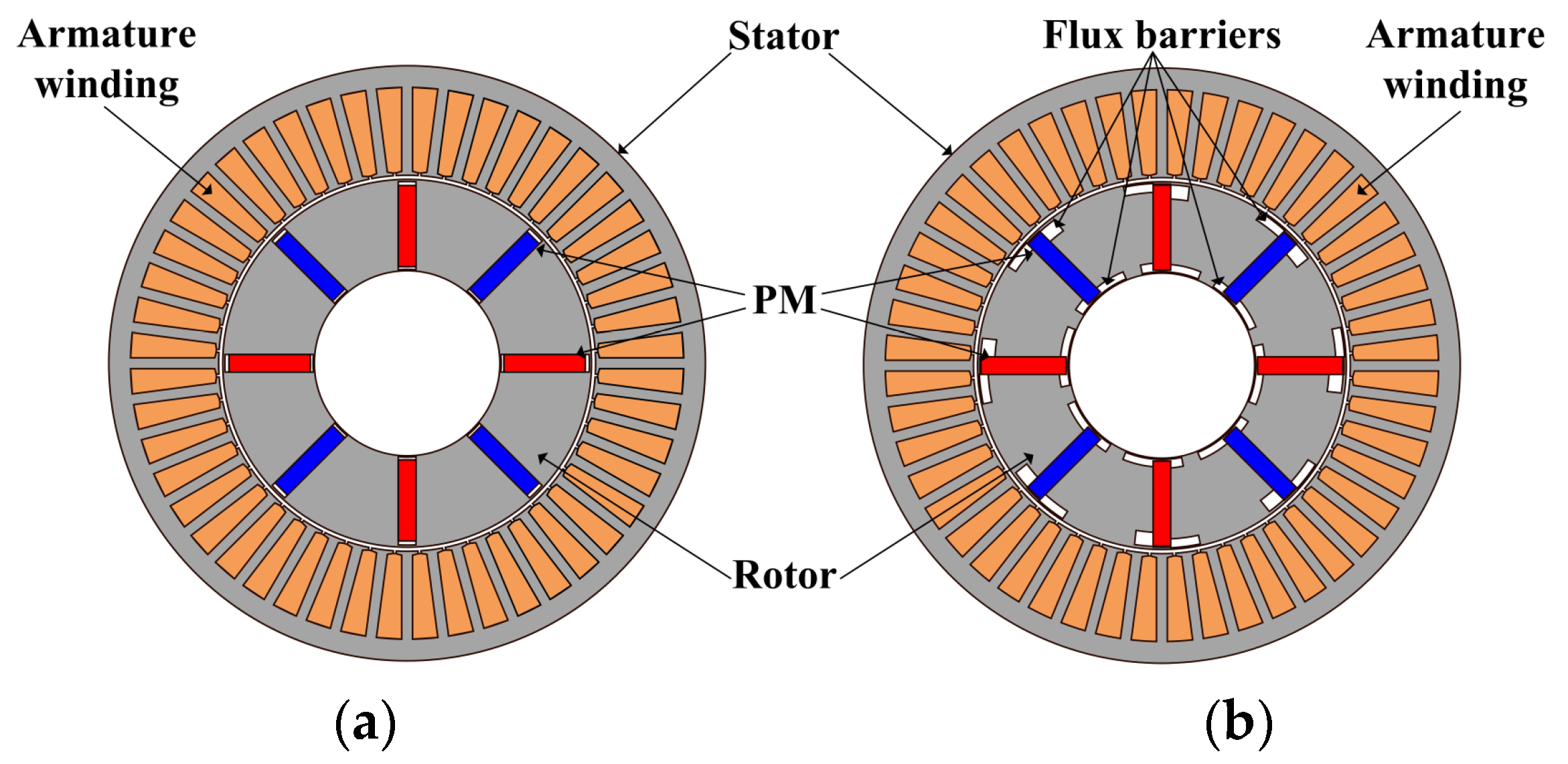
2. Machine Structure and Operation Principle

A conventional 48-slot 8-pole S-IPM machine is shown in Figure 1a. The outer diameter is 220 mm, the rated speed is 1500 rpm, and a single-layer distributed winding is adopted. To improve the torque performance of the conventional machine, a novel design technique called the MFS effect, which is realized by an asymmetric rotor structure, is utilized. Consequently, a novel AS-IPM machine is proposed, as shown in Figure 1b. The asymmetric flux barriers are employed in both the inner circumference and outer surface of the rotor. To make a fair comparison, the main design parameters are kept the same as listed in Table 1.
According to [9,27], the output torque that consists of PM torque and reluctance torque in a conventional S-IPM machine can be expressed as
T e = T m + T r = 3 P 2 ( ψ f d i q + ψ f q i d ) + 3 P 2 ( L d L q ) i d i q = 3 P 2 ψ p m i s cos β + 3 P 4 ( L d L q ) i s 2 sin 2 β = T p m cos β + T r t sin 2 β
where Te, Tm, and Tr represent the synthetic torque, PM torque, and reluctance torque, respectively. is, id, and iq are the phasors of armature current, d-axis, and q-axis current, respectively. ψpm, ψfd, and ψfq are the phasors of synthetic PM flux linkage, d-axis, and q-axis PM flux linkage, respectively. P is the pole pair number, and β is the current advancing angle.
{ T p m = 3 P 2 ψ p m i s T r t = 3 P 4 ( L d L q ) i s 2
Theoretically, the angle difference between the peak values of PM torque and reluctance torque is 45 electrical degrees in a conventional symmetrical structure. The utilization ratios of both torque components are low. Different from the conventional design, torque improvement is achieved by utilizing PM torque and reluctance torque components better without any extra cost, which is known as the so-called MFS effect. The asymmetric structure can shift the current angle of the peak values of two torque components and reduce the angle difference between them. Hence, the synthetic torque of the proposed AS-IPM machine can be obtained by
T e = T m + T r = 3 P 2 ( ψ f d i q + ψ f q i d ) + 3 P 2 ( L d L q ) i d i q = 3 P 2 ψ p m i s cos ( β α s ) + 3 P 4 ( L d L q ) i s 2 sin 2 β = T p m cos ( β α s ) + T r t sin 2 β
where αs is the asymmetric angle in the AS-IPM machine. Intuitively, the torque can be improved by shifting the maximum point of PM torque and reluctance torque, which is achieved by adjusting αs in the AS-IPM machine, as shown in (3).

3. Design Optimization

The conventional S-IPM machine is optimized at first to make a relatively fair comparison. To obtain a wide variety of asymmetric rotor structures, a general pattern is proposed to cover as many rotor topologies as possible.

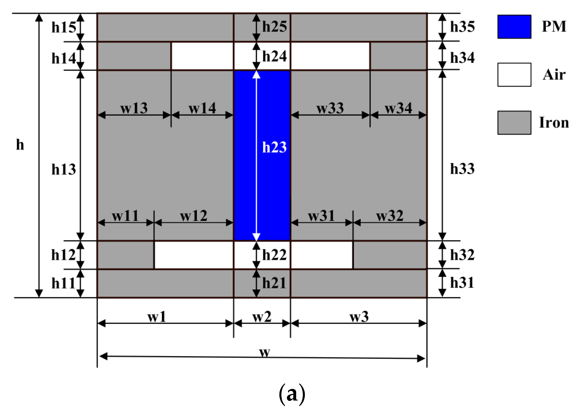
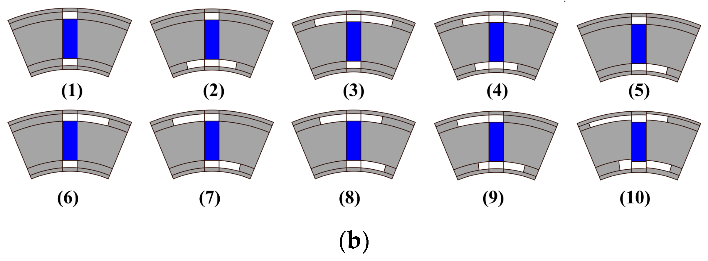
3.1. General Pattern
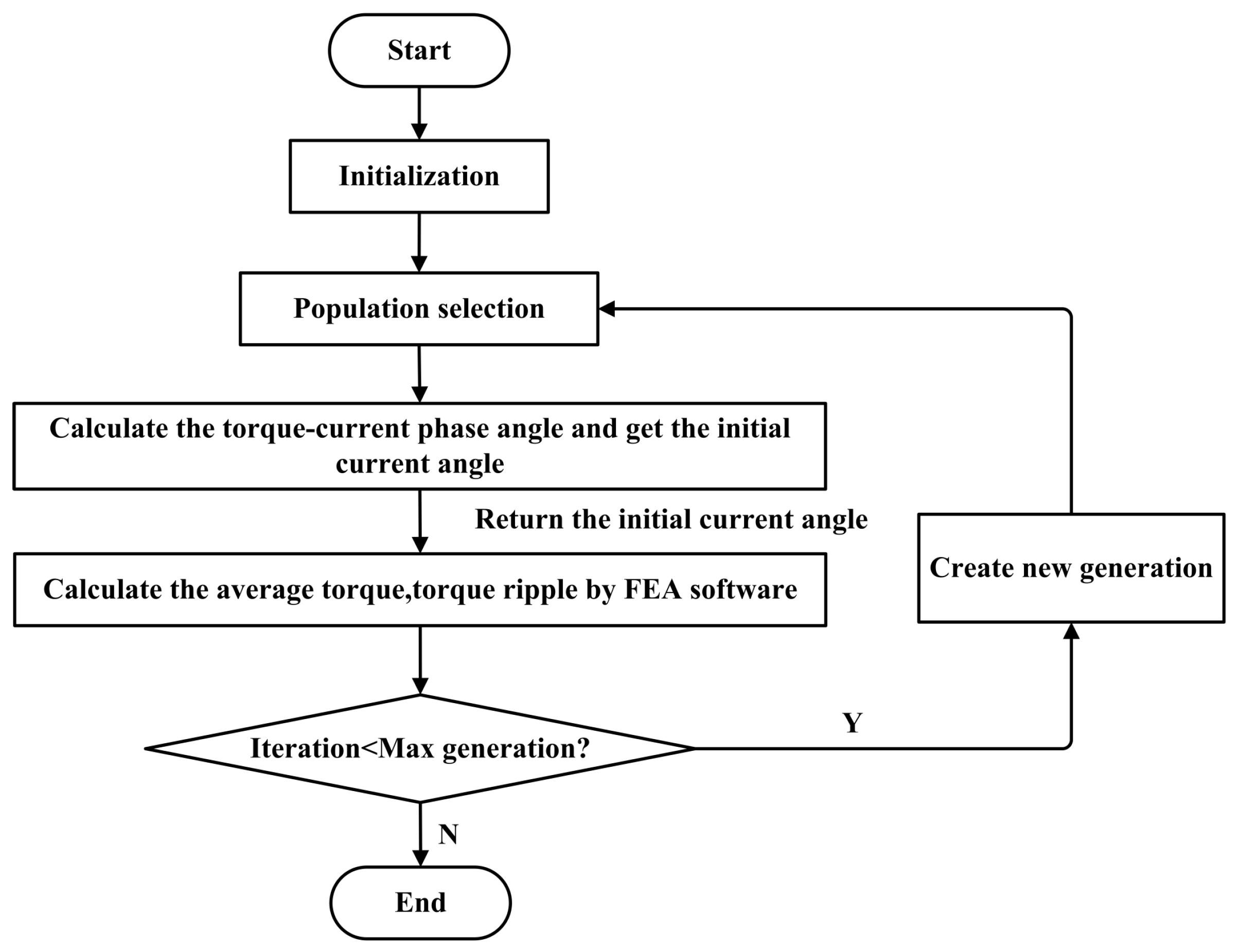
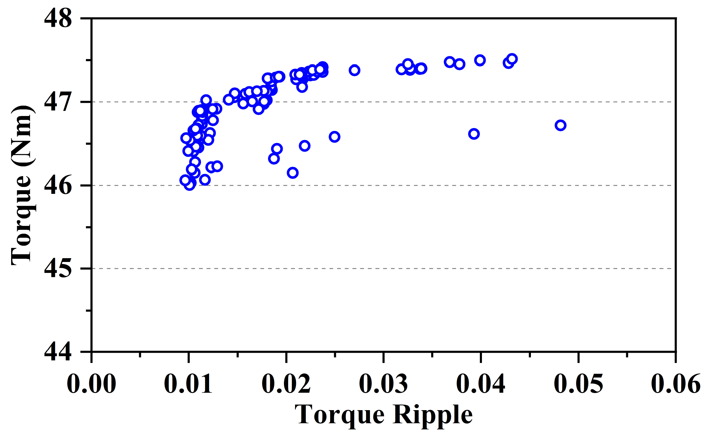
This general pattern can represent diverse topologies by changing its geometrical parameters, as shown in Figure 2.
In the general pattern, if w14 = 0, w12 = 0, w33 = 0, and w31 = 0, or h14 = 0, h34 = 0, h12 = 0, and h32 = 0, the conventional S-IPM can be obtained, which is the first rotor topology in Figure 2b.
If w14 = w33, h13 = h33, w12 = w31, and h12 = h32, the general pattern will lead to the S-IPM with a symmetrical flux barrier structure, which can strengthen the flux-focusing effect. It is shown in Figure 2b as the second to fourth rotor topologies.
Otherwise, the remaining asymmetric rotor topologies in Figure 2b can be generated with the combinations of arbitrary rotor design parameters. The asymmetric rotor structure can effectively use the MFS effect, which reduces the current difference angle between the maximum value of reluctance torque and PM torque to improve performance.
It should be mentioned that the proposed optimization method with a general pattern has two restrictions. On the one hand, the general pattern for optimizing the asymmetric flux barriers is utilized for achieving the MFS effect, which is only suitable for machines with both PM torque and reluctance torque. In other words, the types of electric machines are restricted to IPM machines or PM-assisted synchronous reluctance machines. On the other hand, the proposed method is able to obtain an IPM machine with the optimal structural design of the asymmetric flux barriers with a consideration of the cooperative effect of various flux barriers. However, the flux barriers should be designed in advance and added to the general pattern of rotor topology. As a result, novel flux barriers are required to be manually added to the existing general pattern of the rotor topology to enhance the practicability.

3.2. Optimization

In this paper, a non-dominated sorting genetic algorithm II (NSGA-II) is employed to find the optimal structures [28,29]. The optimization algorithm is coupled directly to the finite element analysis (FEA) to achieve a fully automatic process. The objectives are maximizing the average output torque and minimizing the torque ripple, which can be expressed as
m i n { f 1 ( x ) ,     f 1 ( x ) = T a v g f 2 ( x ) ,     f 2 ( x ) = T r i p p l e
where Tavg refers to the average output torque and Tripple is the torque ripple.
The design variables shown in Figure 2 and their variation range are given in Table 2. Meanwhile, the constraints of the optimization process are listed as
{ V P M = 30   mL R i n = 35.6   mm T a v g 40   Nm T r i p p l e 15 %
where VPM is the PM volume, and Rin is the rotor inner radius.
The number of optimization generations is selected as 60, and the population in each generation is 100. In addition, the crossover factor and the mutation factor are chosen as 0.8 and 0.05, respectively. The process of the optimization is shown in Figure 3. It is worth noting that, different from the traditional optimization process, the current angle of maximum torque is also taken into account during the optimization. After initializing the design parameters, the design parameters generated by the algorithm are passed to FEA, and the current angle of maximum torque is calculated and returned first. Then, the current excitations of armature winding are modified by adding the initial current angle. As a result, the corresponding values of output torque and torque ripple are simulated by using FEA, and the results are returned to the algorithm for fitness evaluation. This additional step can significantly improve the calculation accuracy, which considers the change in the initial current angle caused by the MFS effect.
The optimization results of average torque and torque ripple are given in Figure 4. The Pareto front shows the tradeoff between the average torque and the torque ripple. Therefore, improving the torque without degrading the torque ripple is impossible. The optimal design is selected with the criteria of the largest average torque with a torque ripple lower than 2%. On the one hand, the h14 and w33 of the optimized rotor structure are largely reduced, as shown in Figure 5a. The flux barriers near the outer surface have little effect on performance improvement. On the other hand, the h12 and h32 of the optimized structure are increased, which makes the inner circumference flux barriers more obvious than in the original AS-IPM machine. Thus, the inner circumference flux barriers make the main contribution to the improvement in torque performance.

4. Performance Analysis and Comparative Study

To exhibit the merit of the proposed AS-IPM machine, the performance of the machine is analyzed based on FEA and compared to the conventional S-IPM machine. For a fair comparison, both machines are optimized, and the detailed design parameters are shown in Table 3.

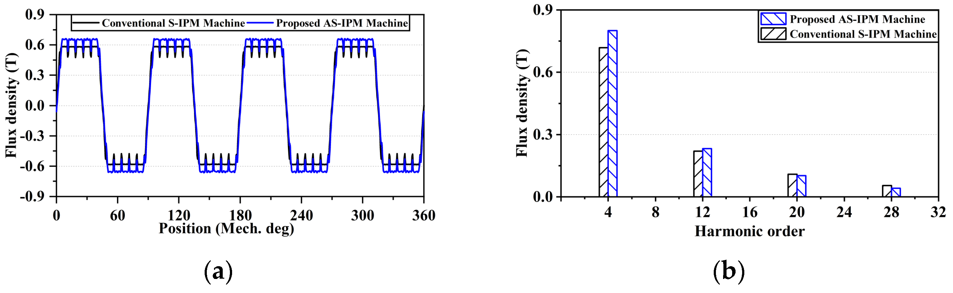
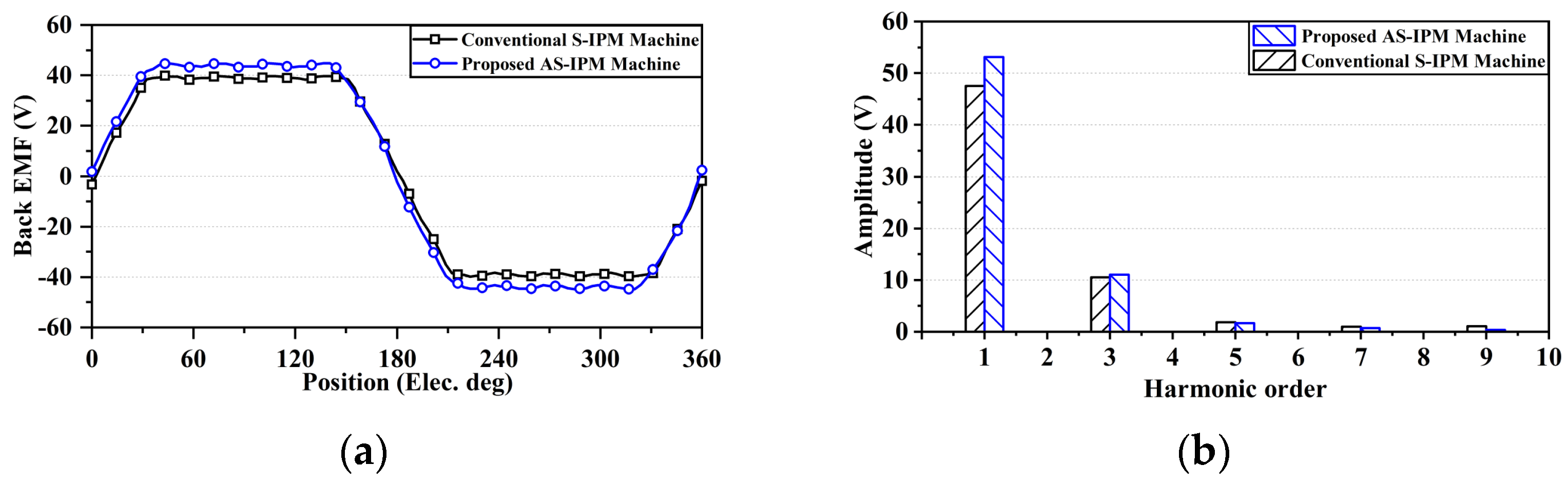
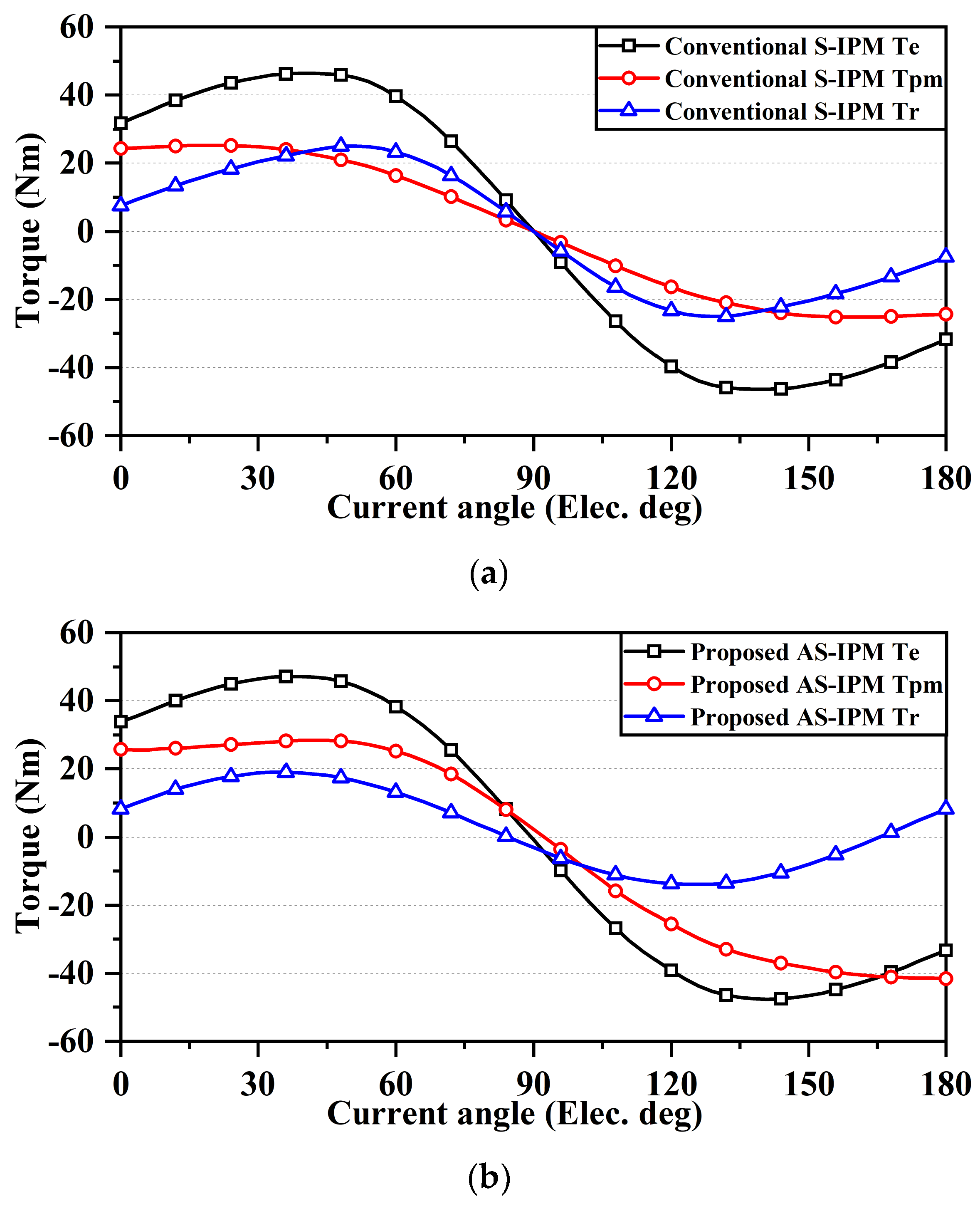
4.1. The Effect of the Asymmetric Flux Barriers on Machine Performance

Figure 6 shows the optimal structures of both machines and their open-circuit magnetic field distribution. The corresponding flux line distribution is also given in Figure 7. It is clear that the asymmetric flux barriers of the proposed machine strengthen the flux-focusing effect and restrain a part of flux leakage. Hence, the utilization ratio of the PM and iron core is largely improved.
The no-load air gap flux density waveforms and the space harmonics are shown in Figure 8. Compared with the conventional S-IPM machine, the air gap flux density of the proposed AS-IPM machine is increased due to the improvement in the PM and iron core utilization ratio. As shown in Figure 8b, it is obvious that the magnitude of the fundamental working harmonic of 4 pole pairs has a notable increase.
The waveforms and spectra of the no-load back electromotive force (EMF) of Phase A are compared in Figure 8. It is clear that the proposed AS-IPM has a higher amplitude of back EMF. A slight axis shifting, which indicates the MFS effect, can also be observed in Figure 9a. Furthermore, as shown in Figure 9b, the AS-IPM also has a higher fundamental component and lower total harmonic distortion (THD), which contributes to better torque performances.
Figure 10 further reveals the mechanism of the torque enhancement in the proposed AS-IPM machine. A frozen permeability (FP) method [30,31] is adopted to accurately extract different torque components, including PM torque and reluctance torque in both machines. To perform an accurate torque calculation, the magnetic saturation and cross-coupling could not be ignored, which leads to a non-linear problem of separating two torque components. Hence, the synthetic torque is first obtained with all excitations. Then, the on-load permeability is saved and frozen, which changes the non-linear problem to the linear one. Consequently, the reluctance torque and PM torque could be well separated based on the FP method. Figure 10a,b depict the torque components versus the current advancing angles of both machines. Obviously, the PM torque and reluctance torque components reach the maximum values at different current angles, particularly in the conventional S-IPM machine. This results in a low utilization ratio of both PM torque and reluctance torque. In the conventional S-IPM machine, the angle difference between the peak values of the two torque components is quite large, which is about 33 electrical degrees. However, the angle difference in the proposed AS-IPM machine has been greatly reduced to only 9 electrical degrees. Therefore, the utilization of both torque components is improved, and the output torque is effectively increased in the proposed AS-IPM machine.

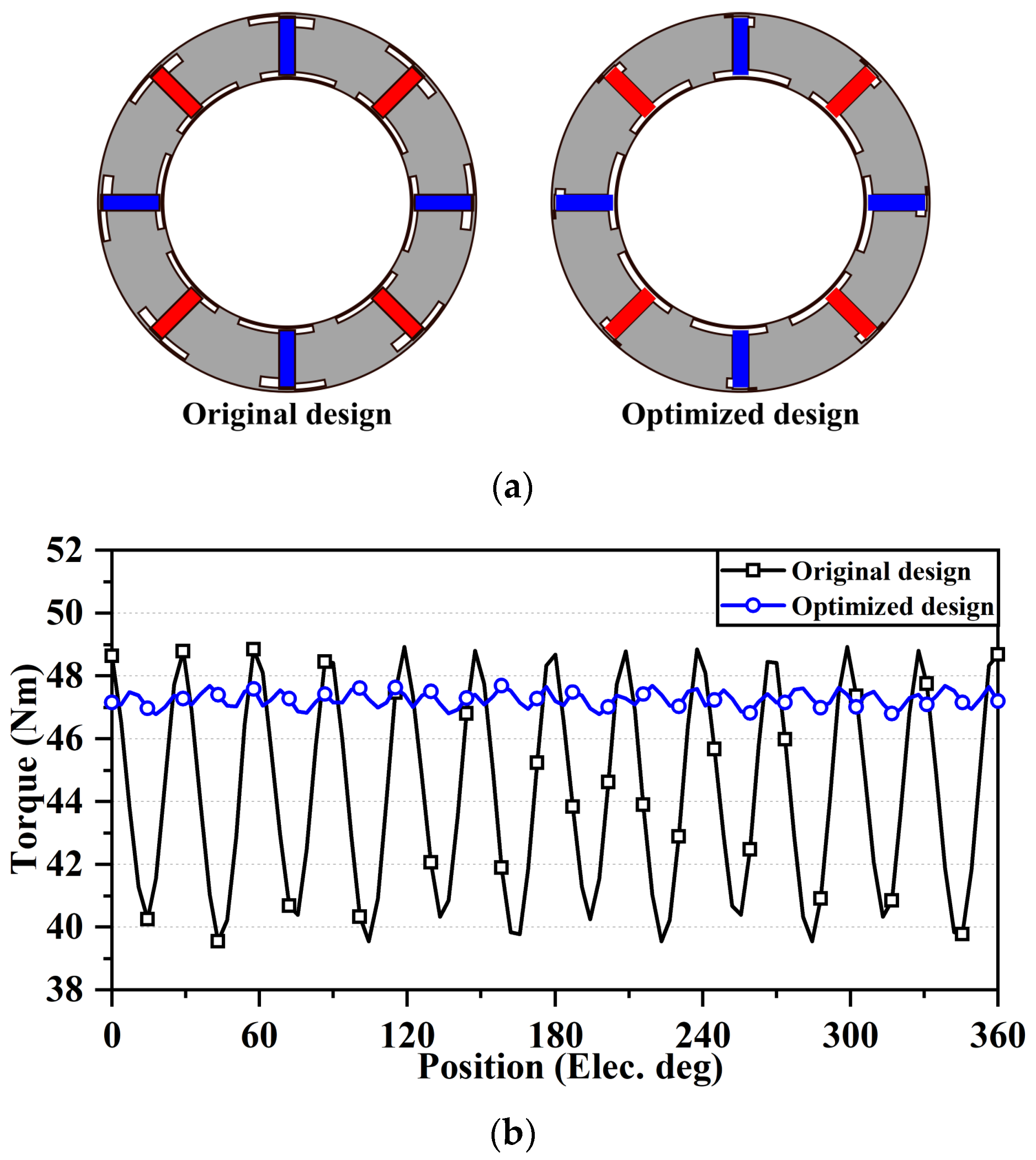
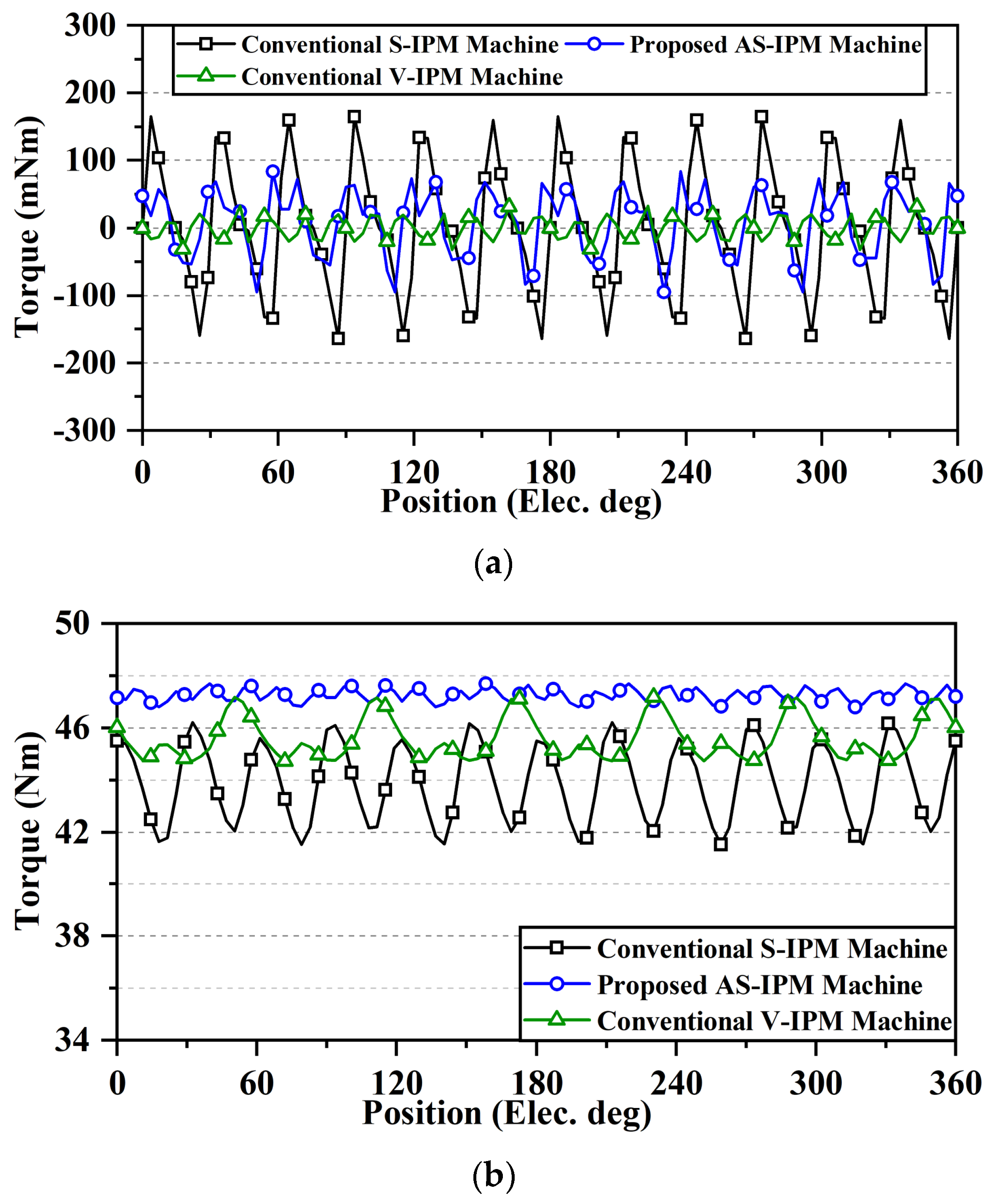
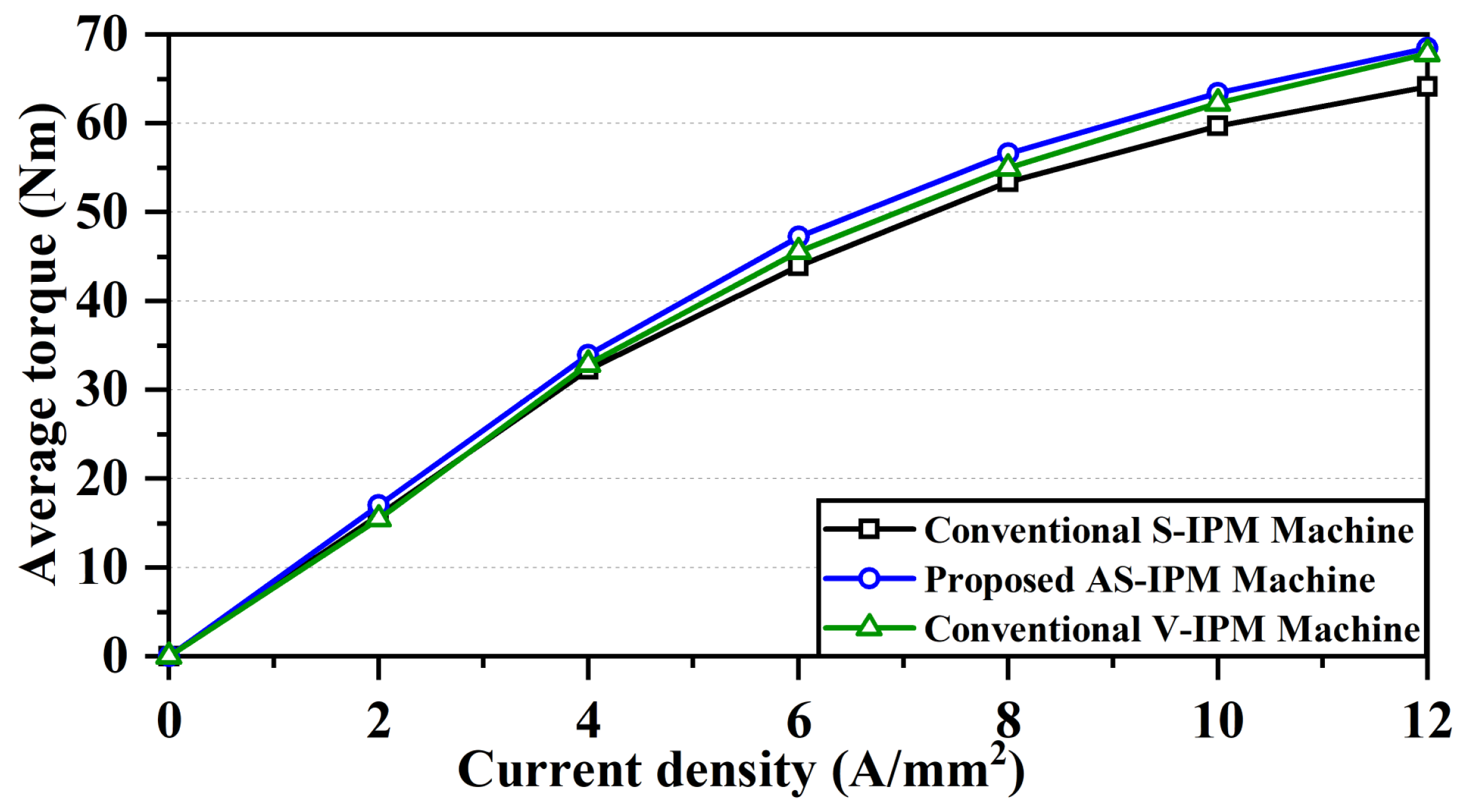
4.2. Performance Comparison of Conventional and Proposed Machines

In order to demonstrate the advantages of the proposed AS-IPM machine, a conventional V-shaped IPM (V-IPM) machine is also included in this part to achieve a comprehensive comparison. Figure 11 shows the torque comparison between the conventional IPM machines and the proposed AS-IPM machine. It can be observed in Figure 11a that the V-IPM machine has the lowest cogging torque, which is 0.065 Nm (peak-to-peak). Due to the facilitation of asymmetric flux barriers, the cogging torque of the proposed AS-IPM machine is significantly reduced, which is only 54.4% of the peak-to-peak value of the conventional S-IPM machine. As shown in Figure 11b, the output torque of the conventional V-IPM at a rated condition is 45.56 Nm, which is larger than the conventional S-IPM machine. However, the utilization of an asymmetric rotor structure in the proposed AS-IPM machine greatly improves the torque performance. The average torque increases by 7.7%, from 43.88 Nm to 47.255 Nm, and the torque ripple is reduced by 82.1%, from 10.67% to 1.91%. Therefore, the proposed AS-IPM exhibits the highest average torque and lowest torque ripple compared to both conventional IPM machines.
Figure 12 compares the average torque under different current densities. The proposed AS-IPM machine produces a higher average torque than the conventional IPM machines in the whole current range, and all the machines perform relatively good linearity. In addition, the more detailed performances of machines are also studied and listed in Table 4. Due to the same stator design, all machines have the same copper loss of 373.88 W. The conventional V-IPM has the lowest core loss, while conventional S-IPM and proposed AS-IPM machines are slightly elevated. The PM losses are very small in these IPM machines, which are ignored in the analysis of efficiency. Compared with the two conventional IPM designs, the proposed AS-IPM motor has the highest output torque. Therefore, compared with the conventional S-IPM and V-IPM machines (with respective efficiencies of 92.94% and 93.25%), the efficiency of the proposed machine (93.41%) is slightly improved.

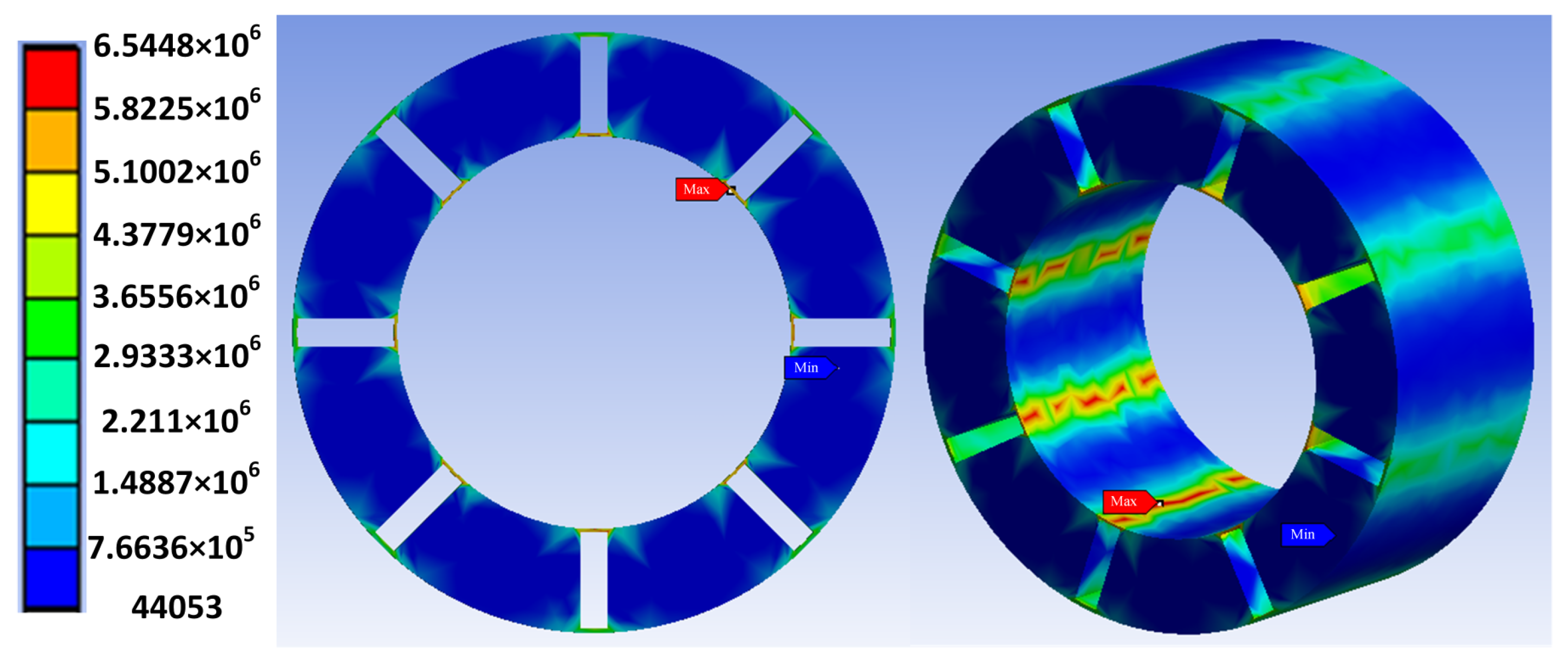
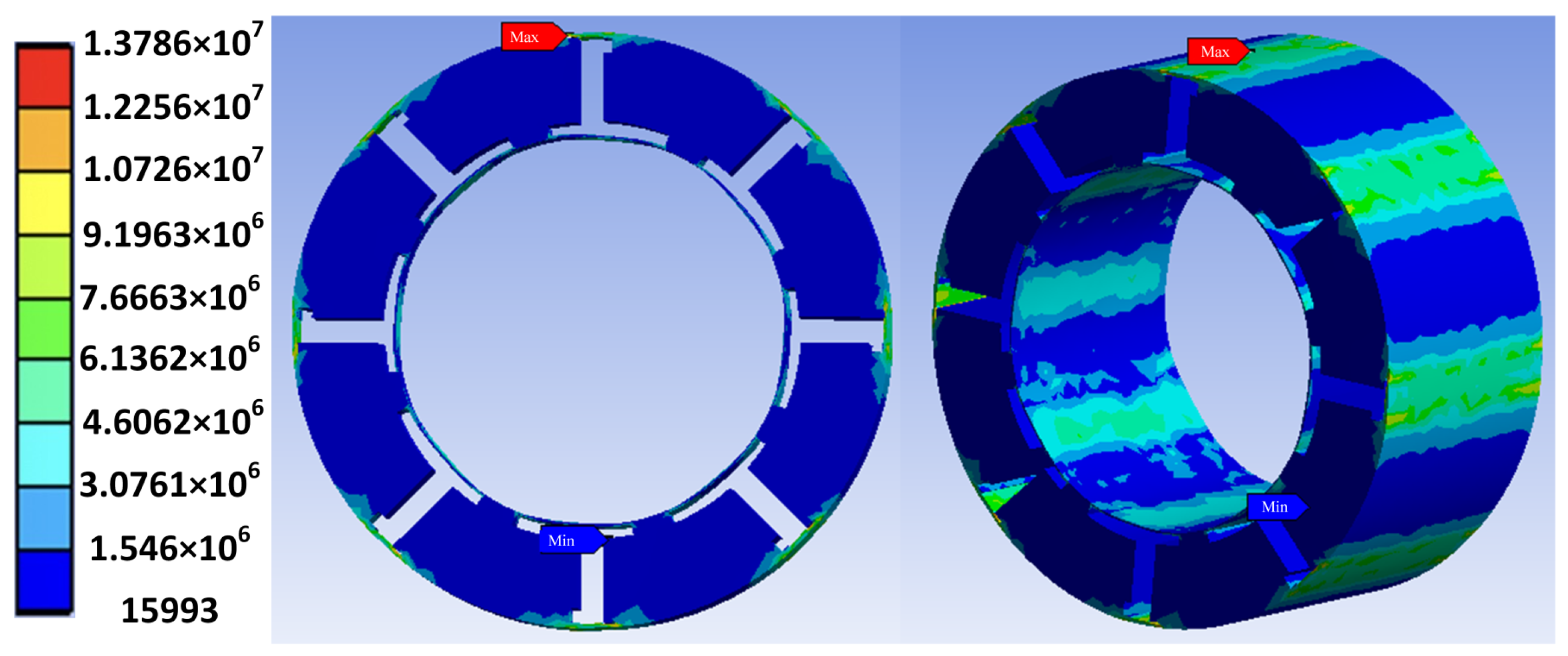
4.3. Mechanical Analysis

The stress analysis is performed on the rotors of the conventional S-IPM and proposed AS-IPM machines. Figure 13 and Figure 14 show the equivalent stress on the rotor of conventional and proposed machines, respectively. It can be found that the maximum stress of the conventional rotor occurs at the inner flux bridge while it occurs at the outer flux bridge of the proposed asymmetric rotor. The maximum stress is 6.545 MPa on the conventional rotor, while 13.786 MPa on the proposed asymmetric. However, the maximum value of stress is increased in the proposed rotor structure. It is still much less than the yield strength of the material.

5. Conclusions

This paper proposes a novel 48-slot 8-pole AS-IPM machine that utilizes the MFS effect to improve the torque performance without the extra use of PM materials. The special asymmetric rotor structure effectively reduces the current angle difference between the PM torque and reluctance torque components. A general pattern is applied to generate different structures with various flux barriers. With the assistance of the optimization program, an asymmetric spoke-type rotor structure with better performance is obtained in a short time. In addition, the FP method is applied in the performance analysis to accurately evaluate the contribution of PM torque and reluctance torque to the synthetic torque. It shows that the proposed AS-IPM machine with asymmetric flux barriers performs better torque characteristics than the conventional S-IPM machine with the same PM usage. The average torque improves by 7.7%, and the torque ripple reduces by 82.1% simultaneously. Moreover, the efficiency of the proposed machine is as high as 93.41%, which is notably improved compared to the conventional machine. Consequently, the machine manufacturing cost can be effectively reduced, as the volume of the total machine can be decreased due to the improved torque density. Meanwhile, the possible vibration and noise problem can be alleviated as the torque ripple is greatly reduced. It should also be mentioned that the fabrication of the proposed asymmetric rotor structure would be relatively complicated due to the extra flux barriers. However, performance improvements can compensate for manufacturing difficulties. Therefore, the proposed AS-IPM machine is a competitive candidate among IPM machines.

Author Contributions

Conceptualization, W.F., J.H. and Y.B.; methodology, W.F., J.H., S.N. and X.Z.; validation, J.H.; optimization, Z.Q.; data visualization, J.H. and Y.B.; writing—original draft preparation, J.H.; writing—review and editing, W.F., S.N. and X.Z.; supervision, W.F., S.N. and X.Z.; funding acquisition, S.N. All authors have read and agreed to the published version of the manuscript.

Funding

This research was funded by the Research Grant Council of the Hong Kong SAR Government under projects PolyU PolyU152185/18E and PolyU152180/19E.

Data Availability Statement

Not applicable.

Conflicts of Interest

The authors declare no conflict of interest.

References

  1. Chau, K.T.; Chan, C.C.; Liu, C. Overview of permanent-magnet brushless drives for electric and hybrid electric vehicles. IEEE Trans. Ind. Electron. 2008, 55, 2246–2257. [Google Scholar] [CrossRef] [Green Version]
  2. Azar, Z.; Zhu, Z.Q.; Ombach, G. Investigation of torque-speed characteristics and cogging torque of fractional-slot IPM brushless AC machines having alternate slot openings. IEEE Ind. Appl. 2012, 48, 903–912. [Google Scholar] [CrossRef]
  3. Niu, S.; Wang, S.; Zhao, X. Overview of stator slot-opening permanent magnet machines. IEEE Trans. Transp. Electrif. 2022, 2, 1561. [Google Scholar] [CrossRef]
  4. Guan, Y.; Zhu, Z.Q.; Afinowi, I.A.A.; Mipo, J.C.; Farah, P. Comparison between induction machine and interior permanent magnet machine for electric vehicle application. In Proceedings of the 2014 17th International Conference on Electrical Machines and Systems (ICEMS), Hangzhou, China, 1–4 October 2014; pp. 144–150. [Google Scholar]
  5. Fasolo, A.; Alberti, L.; Bianchi, N. Performance comparison between switching-flux and IPM machines with rare-earth and ferrite PMs. IEEE Trans. Ind. Appl. 2014, 50, 3708–3716. [Google Scholar] [CrossRef]
  6. Kim, M.; Zhao, F.; Lipo, T.A. Torque density elevation in concentrated winding interior PM synchronous motor with minimized magnet volume. IEEE Trans. Magn. 2013, 49, 3334–3337. [Google Scholar] [CrossRef]
  7. Wang, A.; Jia, Y.; Soong, W.L. Comparison of five topologies for an interior permanent-magnet machine for a hybrid electric vehicle. IEEE Trans. Magn. 2011, 47, 3606–3609. [Google Scholar] [CrossRef]
  8. Liu, X.; Chen, H.; Zhao, J.; Belahcen, A. Research on the performances and parameters of interior PMSM used for electric vehicles. IEEE Trans. Ind. Electron. 2016, 63, 3533–3545. [Google Scholar] [CrossRef]
  9. Zhu, Z.Q.; Xiao, Y. Novel magnetic-field-shifting techniques in asymmetric rotor pole interior PM machines with enhanced torque density. IEEE Trans. Magn. 2022, 58, 1–10. [Google Scholar] [CrossRef]
  10. Zhao, W.; Zhao, F.; Lipo, T.A.; Kwon, B.-I. Optimal design of a novel V-type interior permanent magnet motor with assisted barriers for the improvement of torque characteristics. IEEE Trans. Magn. 2014, 50, 1–4. [Google Scholar] [CrossRef]
  11. Xiao, Y.; Zhu, Z.Q.; Chen, J.T.; Wu, D.; Gong, L.M. A novel V-shape interior permanent magnet synchronous machine with asymmetric spoke-type flux barrier. In Proceedings of the 2020 International Conference on Electrical Machines (ICEM), Virtual Conference, 23–26 August 2020; pp. 382–388. [Google Scholar]
  12. Xu, G.; Liu, G.; Zhao, W.; Chen, Q.; Du, X. Principle of torque-angle approaching in a hybrid rotor permanent-magnet motor. IEEE Trans. Ind. Electron. 2019, 66, 2580–2591. [Google Scholar] [CrossRef]
  13. Li, Y.; Yang, H.; Lin, H.; Fang, S.; Wang, W. A Novel Magnet-Axis-Shifted Hybrid Permanent Magnet Machine for Electric Vehicle Applications. Energies 2019, 12, 641. [Google Scholar] [CrossRef] [Green Version]
  14. Zhao, W.; Lipo, T.A.; Kwon, B.-I. Optimal design of a novel asymmetrical rotor structure to obtain torque and efficiency improvement in surface inset PM motors. IEEE Trans. Magn. 2015, 51, 1–4. [Google Scholar]
  15. Ren, W.; Xu, Q.; Li, Q. Asymmetrical V-Shape rotor configuration of an interior permanent magnet machine for improving torque characteristics. IEEE Trans. Magn. 2015, 51, 1–4. [Google Scholar] [CrossRef]
  16. Xiao, Y.; Zhao, S.W.; Gong, S. A novel asymmetric interior permanent magnet machine for electric vehicles. Trans. Energy Convers. 2021, 36, 2404–2415. [Google Scholar] [CrossRef]
  17. Yoon, K.Y.; Hwang, K.Y. Optimal design of spoke-type IPM motor allowing irreversible demagnetization to minimize PM weight. IEEE Access 2021, 9, 65721–65729. [Google Scholar] [CrossRef]
  18. Bhagubai, P.P.C.; Sarrico, J.G.; Fernandes, J.F.P.; Costa Branco, P.J. Design, multi-objective optimization, and prototyping of a 20 kW 8000 rpm permanent magnet synchronous motor for a competition electric vehicle. Energies 2020, 13, 2465. [Google Scholar] [CrossRef]
  19. Si, M.; Yang, X.Y.; Zhao, S.W.; Gong, S. Design and analysis of a novel spoke-type permanent magnet synchronous motor. IET Electr. Power Appl. 2016, 10, 571–580. [Google Scholar] [CrossRef]
  20. Ge, X.; Zhu, Z.Q.; Li, J.; Chen, J. A spoke-type IPM machine with novel alternate airspace barriers and reduction of unipolar leakage flux by step-staggered rotor. IEEE Trans. Ind. Appl. 2016, 52, 4789–4797. [Google Scholar] [CrossRef]
  21. Liu, W.; Lipo, T.A. Analysis of Consequent Pole Spoke Type Vernier Permanent Magnet Machine With Alternating Flux Barrier Design. IEEE Trans. Ind. Appl. 2018, 54, 5918–5929. [Google Scholar] [CrossRef]
  22. Li, J.; Wang, K. A novel spoke-type PM machine employing asymmetric modular consequent-pole rotor. IEEE/ASME Trans. Mechatron. 2019, 24, 2182–2192. [Google Scholar] [CrossRef]
  23. Xiao, Y.; Zhu, Z.Q.; Jewell, G.W.; Chen, J.; Wu, D.; Gong, L. A novel spoke-type asymmetric rotor interior permanent magnet machine. IEEE Trans. Ind. Appl. 2021, 57, 4840–4851. [Google Scholar] [CrossRef]
  24. Mao, Y.; Zhao, W.; Zhu, S.; Chen, Q.; Ji, J. Vibration investigation of spoke-type PM machine with asymmetric rotor considering modulation effect of stator teeth. IEEE Trans. Ind. Electron. 2021, 68, 9092–9103. [Google Scholar] [CrossRef]
  25. Jung, Y.; Park, M.; Lim, M. Asymmetric rotor design of IPMSM for vibration reduction under certain load condition. IEEE Trans. Energy Convers. 2020, 35, 928–937. [Google Scholar] [CrossRef]
  26. Bi, Y.; Huang, J.; Wu, H.; Fu, W.; Niu, S.; Zhao, X. A general pattern of assisted flux barriers for design optimization of an asymmetric V-shape interior permanent magnet machine. IEEE Trans. Magn. 2022, 58, 1–4. [Google Scholar] [CrossRef]
  27. Yang, H.; Wang, W.; Lin, H.; Zhu, Z.Q.; Lyu, S.; Niu, S. A novel hybrid-pole interior PM machine with magnet-axis-shifting effect. In Proceedings of the 2019 IEEE International Electric Machines and Drives Conference (IEMDC), San Diego, CA, USA, 1–4 May 2019; pp. 273–279. [Google Scholar]
  28. Zhao, X.; Niu, S. Design and optimization of a new magnetic-geared pole-changing hybrid excitation machine. IEEE Trans. Ind. Electron. 2017, 64, 9943–9952. [Google Scholar] [CrossRef]
  29. Zhao, X.; Wang, S.; Niu, S.; Fu, W.; Zhang, X. A novel high-order-harmonic winding design method for vernier reluctance machine with DC coils across two stator teeth. IEEE Trans. Ind. Electron. 2022, 69, 7696–7707. [Google Scholar] [CrossRef]
  30. Chu, W.Q.; Zhu, Z.Q. Average torque separation in permanent magnet synchronous machines using frozen permeability. IEEE Trans. Magn. 2013, 49, 1202–1210. [Google Scholar] [CrossRef]
  31. Hwang, H.; Bae, S.; Lee, C. Analysis and design of a hybrid rare-earth-free permanent magnet reluctance machine by frozen permeability method. IEEE Trans. Magn. 2016, 52, 1–4. [Google Scholar] [CrossRef]
Figure 1. Machine structures. (a) Conventional S-IPM machine; (b) proposed AS-IPM machine.
Energies 15 09385 g001
Figure 2. A general pattern and its derivative structures. (a) General pattern; (b) possible rotor structures derived from the general pattern.
Energies 15 09385 g002aEnergies 15 09385 g002b
Figure 3. Optimization process.
Energies 15 09385 g003
Figure 4. Optimization results.
Energies 15 09385 g004
Figure 5. Comparison of the original and optimized AS-IPM machine. (a) Rotor topologies comparison; (b) output torque comparison.
Energies 15 09385 g005
Figure 6. Open-circuit magnetic field distributions. (a) Conventional S-IPM machine; (b) proposed AS-IPM machine.
Energies 15 09385 g006
Figure 7. Open-circuit flux lines distributions. (a) Conventional S-IPM machine; (b) proposed AS-IPM machine.
Energies 15 09385 g007
Figure 8. No-load air gap flux density. (a) Waveforms; (b) harmonics.
Energies 15 09385 g008
Figure 9. No-load back EMF. (a) Waveforms; (b) spectra.
Energies 15 09385 g009
Figure 10. Torque against current angle curves. (a) Conventional S-IPM machine; (b) proposed AS-IPM machine.
Energies 15 09385 g010
Figure 11. Torque performance comparison. (a) Cogging torque; (b) output torque.
Energies 15 09385 g011
Figure 12. Torque versus current density.
Energies 15 09385 g012
Figure 13. Stress analysis of conventional S-IPM machine (Unit: Pa).
Energies 15 09385 g013
Figure 14. Stress analysis of the proposed AS-IPM machine (Unit: Pa).
Energies 15 09385 g014
Table 1. Main design parameters of both machines.
ParametersValues
Stator slots48
Rotor pole pairs4
Stator outer diameter220 mm
Stack length50 mm
Air gap length0.8 mm
Current density6 A/mm2
Slot filling factor0.5
PM volume30 mL
PM materialN38EH
Rated speed1500 rpm
Table 2. Design parameters and variation range.
ParametersUnitVariation Range
h11, h21, h31 mm0.5–3
h12, h22, h32mm0.2–5
h23 mm12–17
h13, h33 mm10–18
h14, h24, h34 mm0.2–5
h15, h25, h35mm0.5–3
w12, w14, w31, w33degree1–20
w2mm3–8
Table 3. Optimal design parameters of machines.
ParametersConventional S-IPM MachineProposed AS-IPM Machine
Rotor outer diameter (mm)108.8
Rotor inner diameter (mm)71.2
h11 (mm)/0.5
h12(mm)/1.93
h13 (mm)/15.4
h14 (mm)/0.37
h15 (mm)/0.6
h21 (mm)0.50.5
h22 (mm)10.6
h23 (mm)1516.4
h24 (mm)1.50.5
h25 (mm)0.80.8
h31 (mm)/0.5
h32 (mm)/2.15
h33 (mm)/12.4
h34 (mm)/2.65
h35 (mm)/1.1
w12 (deg.)/8.3
w14 (deg.)/2.4
w2 (mm)54.57
w31 (deg.)/18.6
w33 (deg.)/1.8
Table 4. Performance comparison.
Machine TypeConventional S-IPM MachineConventional V-IPM MachineProposed AS-IPM Machine
Average torque 43.88 Nm45.56 Nm47.255 Nm
Cogging (peak-to-peak)0.329 Nm0.065 Nm0.179 Nm
Torque ripple10.67%5.35%1.9%
Copper loss373.88 W373.88 W373.88 W
Core loss149.8 W144.4 W149.2 W
Efficiency92.94%93.25%93.41%
Publisher’s Note: MDPI stays neutral with regard to jurisdictional claims in published maps and institutional affiliations.

