1. Introduction
Reducing greenhouse gas emissions from heavy-duty road vehicles (HDV) represents an important step in the decarbonization of the transportation sector. Focusing only on European Union (EU), to achieve the target of net-zero emissions agreed in the “European Green Deal” [
1], emissions from heavy-duty vehicles will require a reduction, on average, of 15% and 30% by 2025 and 2030, respectively, compared to the current levels [
2].
Given that 45% of the energy in HDV is currently wasted in the form of heat [
3], the development of waste heat recovery (WHR) technologies appears to be the most effective way to achieve such ambitious targets and at the same time reduce vehicle operating costs [
4]. Among the available alternatives, turbo-compounding [
5,
6], thermoelectric energy recovery [
7] and indirect waste heat recovery through Organic Rankine Cycles (ORCs) [
8] seem the most promising alternatives [
2].
Turbo-compounding technologies are already available on the market [
9], but they allow only the recovery of a certain amount of waste heat [
6]. Thermoelectric generators still present a low technology readiness level and more research is required for their demonstration in a relevant environment and at large scale [
10]. Organic Rankine Cycles are, on the contrary, a more mature technology, which could lead to a more effective waste heat exploitation, allowing to recover the residual thermal power carried from Exhaust Gas Recirculation (EGR), tail pipe exhausts, charge air and engine coolant [
4].
Many researches have been carried out on ORC for WHR applications in heavy-duty engines, but compact and lightweight components design for vehicle integration, limited cooling capacity on board, utilization of an organic working fluid, back-pressure limitations and cost constraints in the industry still hinder the ORC WHR system commercialization [
4,
11].
Due to the high temperature of exhaust gases, the adoption of working fluid with low critical temperature could lead to a mismatch with exhaust gas if a single-stage ORC unit is adopted. Moreover, the large difference between the temperature of exhaust gases and that of the engine cooling water involves the scarce exploiting of the engine cooling waste heat. To overcome this issue, dual loop Organic Rankine Cycles are proposed, where the High Temperature Loop (HTL) ORC is fed by the exhaust gases whereas the Low Temperature Loop (LTL) ORC is driven by the residual heat of HTL and that of jacket cooling water [
12].
Another important challenge is represented by the transient nature of HDV waste heat source. In real driving scenarios, the engine often operates in highly transient conditions, producing exhaust gas whose mass flow rate and temperature sharply varies with time following engine operating conditions. Besides the variable waste heat source, the available cooling capacity also depends on vehicle speed. This leads to operating of the ORC WHR unit in transient conditions, with continuous variations on the working fluid pressure and temperature at the outlet of the evaporator (where the heat recovery occurs) and at the inlet of the condenser to accommodate the variable thermal and cooling loads. Inefficiencies of these two components prevent a useful recovery and make null the mechanical work provided by the unit, which could be transformed easily on electrical energy for a battery storage or the actuation of ICE auxiliaries.
As a consequence, the thermodynamic conditions at the inlet and outlet of the expander vary as well, affecting the machine performance and ultimately the efficiency of the heat-to-power conversion. In addition, extremely high and low thermal loads at the evaporator may lead to undesirable phenomena such as thermal fluid degradation or wet expansion, which can be harmful for the ORC unit limiting its performance and utilization rate. Xie and Yang [
13] demonstrated those aspects, showing that during the usual day by day traffic operation in heavy-duty trucks, the highly transient operating conditions led to frequent shut-downs and startups of the ORC with several switches between operating modes due to undesirable working conditions. As a result, the ORC efficiency decreased from 7.8% to 3.6% with limited availability to recover and convert the engine waste heat into mechanical energy.
To accelerate the commercialization of this technology, it then becomes important to study the ORC dynamic behavior in such transient scenarios to predict the system off-design performance and, consequently, to design suitable and optimized control strategies. The dynamic response of the ORC must consider multiple parameters such as heat exchanger geometry and thermal inertia, working fluid thermal properties and charge along with the ORC system positioning and layout (which affects pipe length).
In the literature, several researches have been conducted on the transient analysis of ORC systems for stationary applications [
14,
15,
16,
17,
18], but few studies are available for transportation vehicles. In such applications, the ORC dynamic response is generally faster because of the smaller component dimensions and reduced fluid volume.
Feru et al. [
19] validated a transient model of an ORC WHR unit mechanically coupled with a 13 L diesel engine. The unit, equipped with two parallel evaporators to enhance the recovery of the waste heat coming from both the EGR and the tail pipe exhausts, has been modelled following a lumped approach for the pump and the piston expander and a moving boundary methodology for heat exchangers. The Moving Boundary methodology has been used also by Huster et al. [
20], where certain model parameters have been identified from a regression analysis of experimental data.
Despite this technique being preferable for control-oriented models because of the reduced computational effort and faster solution times, it is less accurate in predicting certain transient operating conditions as startup or shutdown where, in the heat exchangers, some working fluid phases (liquid, vapor or two-phase mixture) may not be present. On the contrary, one-dimensional (1D) finite volume methodology allows to achieve more accurate results in the above-mentioned cases. This approach has been used in the research of Trabucchi et al. [
21], where the authors analyzed the dynamic response and controllability of a 5 kW ORC bottoming unit equipped with two parallel evaporators.
Similar research has been carried out by Xu et al. [
22]. In both studies. no experimental validation of the models has been provided. However, experimental validation can significantly improve the calibration of parameters used in one-dimensional modelling approaches, which usually introduce several simplifications to reduce the computational effort during simulations.
A validated model has been proposed by Dhanasegaran et al. [
23], where an ORC system equipped with a dynamic radial machine has been studied. Radial turbines, however, differently affect the ORC dynamics and, compared to volumetric machines, are less suitable to operate smoothly under unsteady conditions [
24].
In the literature, the transient behavior of ORC-based power unit fed by the exhaust gases of ICE was treaded. Nevertheless, to the best of our knowledge, there is a lack of experimental and theoretical analysis about the impact of the variation of main operating quantities on the dynamic ORC performance. The dynamic ORC response is a complex topic depending on external parameters (variation of the high and low thermal source) and internal parameters depending on the control system adopted (i.e., mass flow rate of working fluid, expander speed, etc.). In this work, the attention was focused on the ORC transient behavior in terms of the variation of the main operating parameters when the main control variable was changed.
For the application at hand, the control system is based only on the working fluid mass flow rate variation being the expander speed not externally imposed. Hence, to better evidence and understand the dynamic effects of the mass flow rate variation on ORC dynamic behavior, all the external parameters of hot and low thermal source were kept constant.
To perform this analysis, a dedicated experimental campaign was carried out. Moreover, this work aims to propose a one-dimensional transient mathematical model of an ORC unit bottoming a 3.0 L heavy-duty diesel engine. The ORC unit is equipped with an evaporator, a condenser, a volumetric pump and a volumetric scroll expander, which allows more operational flexibility compared to dynamic machines [
25]. The unit is controlled by the mass flow rate variation performed through the pump revolution speed regulation. Concerning the expander, the revolution speed is not a control parameter, so the revolution speed depends on the dynamic equilibrium on the machine shaft.
The modelling approach adopted is more suitable to predict specific transient operations in which the ORC unit operates in particular off-design conditions. The model is validated against experimental data provided by a testing campaign at the dynamic bench.
After validation, sensitivity analysis is carried out on the main system control parameters to assess its influence on the main cycle variables such as maximum pressure, temperature and machine performance. Results of the analysis and related implications are discussed from a dynamic and control perspectives.
2. Experimental Setup
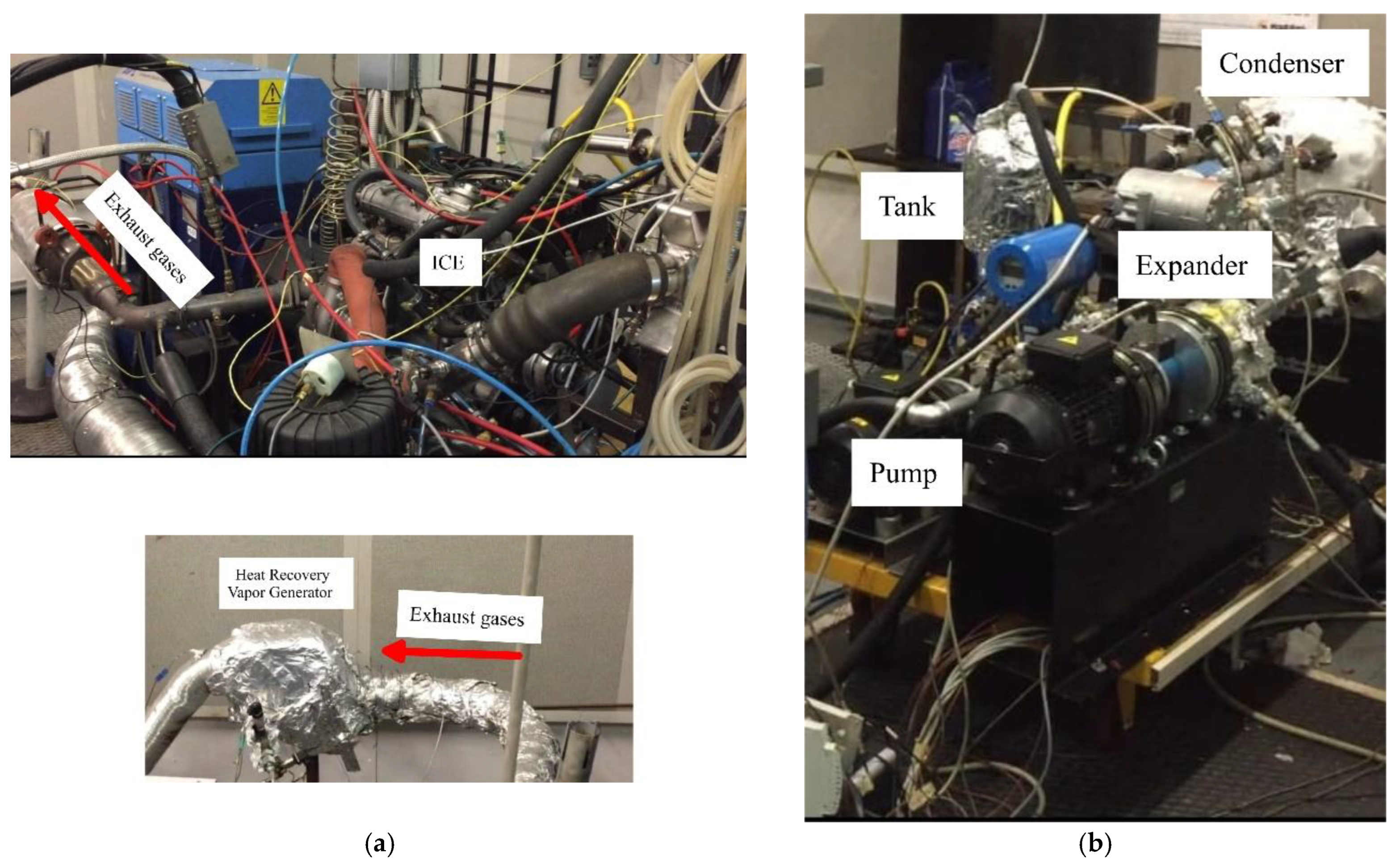
A description of the test bench used for experimental investigation on a 3 L Diesel turbocharged internal combustion engine (ICE) integrated with an ORC unit for the recovery of the thermal power of the ICE exhaust gas is provided in this section. The ICE is showed in
Figure 1a: it is installed on a dynamic test bench (AVL APA 100) allowing to reproduce steady and transient operating conditions. This is a fundamental feature to assess the dynamic behavior of the whole system, when a WHR unit is bottomed to the ICE. Indeed, the engine torque and speed can be independently varied due to a dedicated control system. Moreover, due to an open ECU (Electric Control Unit), all the ICE parameters can be monitored and changed, assessing the engine behavior and the desired control strategy. The variation of brake torque and revolution speed ensures the reproduction of the variation in ICE working points and, consequently, the thermal power of the exhaust gases. K-thermocouples are used to measure the exhaust temperature along the exhaust line, and all other relevant quantities can be measured around the engine. This allows to evaluate the thermal power available from the exhaust gases, which can be up to 60 kW in this specific engine test bench [
26].
Moreover, an ORC-based unit has been built and bottomed to the exhaust gases of the engine, as shown in
Figure 1b. It is composed of an evaporator, a volumetric expander, a condenser, a tank and a pump. Its dynamic response assessment is the main objective of the present work, and so the ORC plant was fully instrumented to analyze its behavior in transient conditions.
R245fa has been selected as working fluid for the ORC-based power unit for the sake of continuity with previous experimental analysis performed on scroll expander [
27]. Moreover, for the application at hand, it ensures a good compromise between the plant performance and the environmental concerns [
28]. R245fa enters in the evaporator cold side, receiving the thermal power of the exhaust gases flowing on the hot side. The evaporator is a plate and fin heat exchanger that was specifically designed for the application, as it ensures reduction of the backpressure exerted on the ICE [
29].
Once the working fluid leaves the evaporator as a superheated vapor, it enters a 1.5 kW scroll expander [
30]. This size was chosen as a best compromise between the amount of produced power and the space required by the ORC unit on board.
Here, the working fluid expands and the machine produces mechanical power converted in electrical by an electric generator, sharing the same shaft of the scroll as the machine is hermetic. The electric power was measured with an electrical load and electrical power measurement device. This plant configuration implies that the expander speed cannot be imposed as a control parameter, being the results of the dynamic equilibrium on the expander shaft. Hence, the only regulation parameter of the plant is the pump revolution speed, which is varied by a dedicated electrical inverter. The working fluid leaving the expander is condensed in a plate heat exchanger cooled by tap water. Prior to being elaborated by a gear pump, the working fluid is gathered in a 3 L tank in order to dump the pulsation of mass flow rate of R245fa at higher speed. The total working fluid charge inside the plant is equal to 7 kg, a 5% of ISO VG 68 POE oil is injected in the circuit to lubricate the pump and the expander. The engine and ORC test bench scheme is reported in
Figure 2a, where all the relevant measuring points are highlighted. In
Figure 2b, the corresponding thermodynamic cycle of the starting operating point of dynamic analysis is shown.
Figure 2b shows a higher superheating degree (close to 50 °C). It was chosen to ensure a superheted vapor at expander intake port despite the significant R245fa mass flow rate increase perfromed during the experimental test.
Concerning the measurement instruments, thermocouples and pressure transducers are placed upstream and downstream of each component to characterize the thermodynamic cycle. The mass flow rate of working fluid is evaluated with a Coriolis mass flow meter, whereas the one of coolant water at condenser is measured with a magnetic flow meter. The expander power is therefore measured collecting the DC electric current and voltage after the AC/DC conversion. In fact, the expander generator produces a three-phase voltage at variable frequency, which is converted in DC voltage and dissipated on the electric load, where the measurement of the DC electric variables is performed [
30]. Before the converter, the AC frequency is measured with a dedicated oscilloscope in order to assess the expander speed.
Concerning the pump, the torque and speed are measured with a torque-meter to calculate the mechanical power absorbed. The exhaust gas temperatures are measured through two thermocouples introduced at evaporator inlet and outlet sides. The exhaust gas mass flow rate is known through the measurements of the engine charge air mass flow and a hot film flow meter, and the fuel consumption is determined through a fuel balance. In
Table 1, the measurement uncertainties of the adopted instruments are reported.
3. Dynamic Model
The ORC unit has been modelled following a one-dimensional approach.
Figure 3 shows schematic representation of the model in GT-SUITE™. The different components of the ORC system are indicated with uppercase letters while lowercase ones are used to highlight the boundary conditions of the model. The boundary conditions are the revolution speed of the pump (which sets the working fluid flow rate) and the inlet temperatures, pressures and flow rates of heat source and heat sink. For the volumetric expander, the revolution speed is not imposed as a boundary condition, but is calculated from the mass flow rate of working fluid of the system. Indeed, the revolution speed of the expander is not regulated electronically, but is a result of the thermodynamic conditions of the working fluid at the inlet of the machine together with the mass flow rate processed. In particular, it was observed from the experimental analysis that the revolution speed of the expander shows a linear dependence on the mass flow rate processed by the pump.
Pump and expander are considered as lumped objects; pipes and heat exchangers are discretized into more volumes following a staggered grid approach. Manifolds are represented by single volumes. These volumes are eventually connected by boundaries. Scalar variables such as pressure, temperature, density, internal energy and enthalpy are assumed uniform in each sub-volume. On the other hand, vector variables such as mass flux, velocity and mass fraction fluxes are computed at each boundary between two different sub-volumes.
An implicit numerical approach is used to approximate the one-dimensional formulation of algebraic differential Navier–Stokes equations into nonlinear algebraic, which are eventually solved iteratively. The solution values at the next time step are simultaneously provided to all the sub-volumes of a given model (e.g., pipes divisions, heat exchangers channels, etc.) [
31]. The thermodynamic properties of the working fluid in the different parts of the circuit are calculated via NIST REFPROP™ [
32], which is interfaced with the solver through a dynamic link library. Finally, connections between these devices are made through piping sub-models, also discretized throughout. The electric machines connected to pump and turbine are not modelled in this work, so the power quantities considered are purely mechanical. In the following paragraphs, a more detailed description of each component is provided.
3.1. Evaporator and Condenser
The evaporator and the condenser are considered as equivalent one-dimensional channels, and then discretized in different sub-volumes according to the approach described above. The main scalar thermodynamic quantities of the working fluid are calculated and assumed constant along each sub-volume; vector quantities (as the mass or the flow velocity) are calculated at their boundaries [
31]. The vector quantities plus the pressure and the total enthalpy of the fluid are computed by solving the one-dimensional continuity, momentum and enthalpy equations (Equations (1)–(3)). The variation in time of the working fluid mass in the heat exchangers and pipes is calculated with the continuity Equation (1), accounting for the algebraic sum of all the inflow and outflow contributions from the neighboring capacities that occur through the boundaries of a given sub-volume [
31].
Similarly, the change in time of the working fluid mass flow rate is calculated through the momentum equation reported in (2), which considers the momentum coming from pressure forces (first term on the right-hand side of Equation (2)), the algebraic sums of momentums through the boundaries of the sub-volumes (second term) and the dissipations due to friction (third term) and pressure drops (fourth term). Body forces are neglected [
31].
Variations of energy are calculated following the energy equation (Equation (3)) expressed as an enthalpy balance because of the implicit solution method [
31]. The heat transfer coefficient h in Equation (3) is calculated using heat transfer correlations. Firstly, the location in the heat exchangers where the phase change occurs is predicted by evaluating the fluid density in each sub-volume, afterwards the extension of the two-phase area is computed following the vapor Rayleigh–Plesset formulation [
33], reported in Equation (4). Eventually, different heat transfer correlations are used depending on the phase of the working fluid and the type of heat exchanger considered. For the evaporator, the correlation proposed by Colburn (Equation (5)) is used for the single-phase heat transfer [
34] and the one proposed by Kandlikar (Equation (6)) for the two-phase region [
35].
For the condenser, the correlation proposed by Dittus Boelter [
36] is used for the single-phase heat transfer (Equation (7) if the fluid is being heated or Equation (8) if the fluid is being cooled), and the one proposed by Yao et al. [
37] is considered for the two-phase region (Equation (9)).
The terms Co, Bo and Re
eq are, respectively, the convection, the boiling and the equivalent Reynolds numbers, and they can be calculated according to Equations (10)–(12).
The thermal inertia due to the heat exchanger material is also discretized along the flow path. In particular, depending on the discretization length (60 sub-volumes), a series of metallic blocks is generated based on the geometrical characteristics of the heat exchanger (dimensions, number of passes, presence of fins, etc.) and the temperature dependency on the physical properties of the material such as thermal conductivity, specific heat and density. Because of some simplifying assumptions introduced by the one-dimensional modelling approach, a coefficient is considered to calibrate the dynamic response of heat exchangers to the experimental data.
Table 2 summarizes the different modelling assumptions and inputs adopted for the evaporator and condenser.
3.2. Volumetric Gear Pump and Scroll Expander
The pump has been considered as a lumped component because of its much faster dynamics compared to heat exchangers. The mass flow rate elaborated by the gear pump can be expressed as per Equation (13).
where the revolution speed and the volumetric efficiency of the pump are model inputs and the volumetric flow rate depends on the geometrical characteristics of the pump, i.e., radius of driving and driven gears, width of gear teeth, number of teeth in the gears, pressure angle and gear revolution speed, and is calculated following the model developed by Manring and Kasaragadda [
40].
Concerning the power required by the pump, it was evaluated dividing the hydraulic power by the pump efficiency (14).
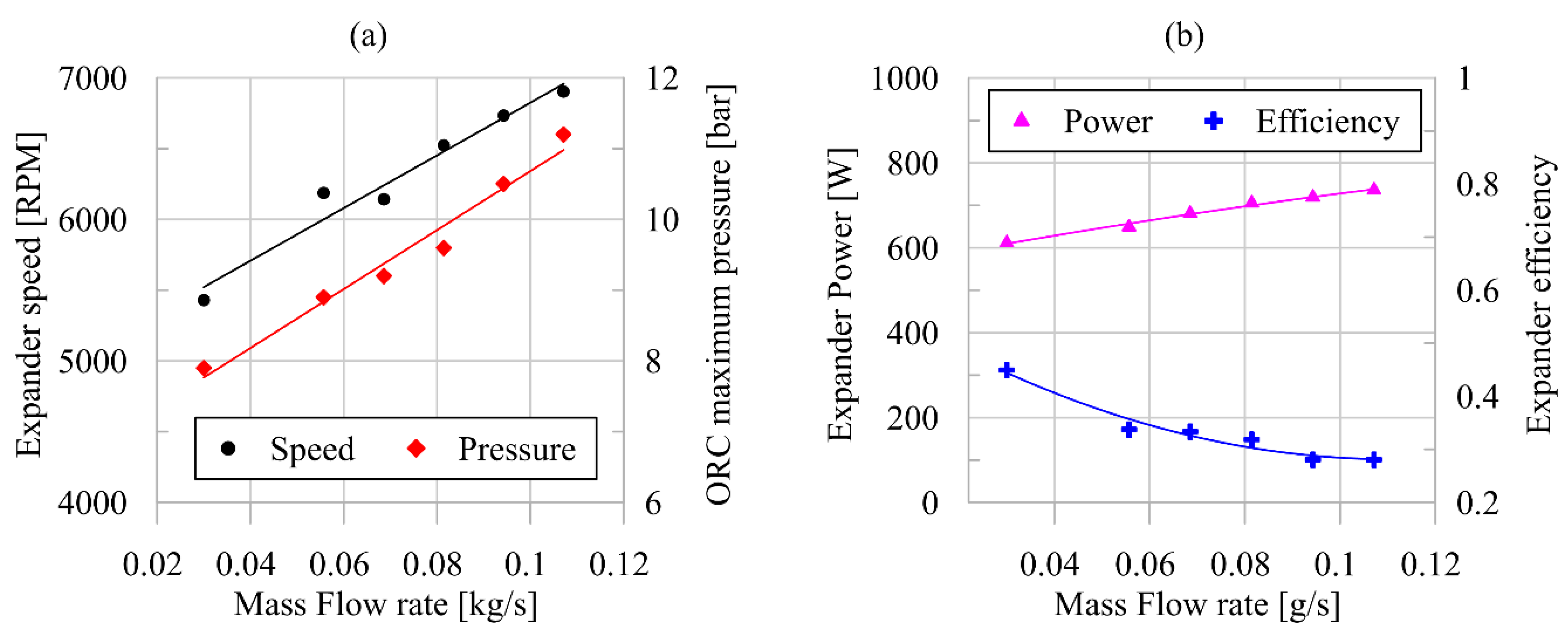
The hydraulic power was obtained as the product of volumetric flow rate and pressure rise. Concerning the efficiency of the pump, it was evaluated with an operating map which was experimentally developed. Considering the experimental results, it was observed as the main driver of the pump power, and efficiency variation is the provided mass flow rate value which is basically defined by the pump revolution speed. This relation is clear observing the linear growth of mass flow rate with pump speed observed in
Figure 4a. With the increase in pump speed, the power required by the pump follows a parabolic trend growing from 121 W up to 370 W when the revolution speed increases from 200 up to 550 RPM. The higher power required by the pump is due to the low efficiency values of the machine (
Figure 4b) whose maximum value (0.2) is achieved in correspondence of a mass flow rate equal to 0.07 kg/s. The low efficiency of the pump in such ORC system is well known in literature and it is due to the fact that, generally, this machine is not optimized for the specific application. An improvement of pump performance trough design optimization provide a significant enhancement of whole ORC unit efficiency [
30,
41].
Hence, this parameter could severely erode the power produced by the expander and cannot be neglected. To account for this impact, the Backwork ratio was considered (15), expressing the pump power impact on that produced by the expander.
Similarly to the pump, the scroll expander has also been modelled as a lumped component; different operating points at design and off-design conditions were used to calculate the performance and isentropic efficiency map of the machine.
The maps were developed with an experimental characterization performed on the expander (
Figure 5). The map reported a set of operating points defined by the expander speed, the mass flow rate, the expander intake and exhaust pressure and the expander efficiency. The input of the map is the mass flow rate, the expander speed and the exhaust pressure. In this case, the expander speed is not externally imposed but linearly depends on the mass flow rate provided by the pump. Hence, there were only two independent variables: the mass flow rate and the expander exhaust pressure. The former depends on the expander speed, and the latter on the condition of the low thermal source. Hence, entering the mass flow rate of working fluid and sensing the exhaust pressure according to the low source condition, the speed, the intake pressure and the power and efficiency of the expander were provided.
The authors also developed specific and physical model for the expander; however, in model environment, the integration of heat exchangers (HRVG and condenser) and rotating machines (pump and expander) is not possible, to the best of our knowledge. Therefore, the dynamic ORC behaviour being basically defined by the HRVG, it was chosen to reproduce a comprehensive and physical model of the heat exchangers, whereas operating map and look up table were used to reproduce the expander and pump performances.
The linear growth of intake pressure with mass flow rate for a scroll machine (
Figure 5a) with a not externally imposed revolution speed was also experimentally observed in [
27]. In [
27] scroll expander was employed in solar-driven ORC-based power unit and its velocity depended on the dynamic equilibrium on the shaft between the torque corresponding to pressure ratio, and the resistance one related to the dissipative electric load. It was noticed experimentally that the volumetric efficiency and revolution speed linearly increases with mass flow rate. Thus, considering that in the relation between pressure and mass flow rate obtained employing the permeability equation [
27] volumetric efficiency and revolution speed are, respectively, at the denominator and numerator, the relation between expander intake pressure and mass flow rate follows a quite linear trend. Thus, when the mass flow rate provided by the pump is enhanced, the expander pressure ratio grows, providing a higher expansion speed for the dynamic equilibrium on the shaft. The speed enhancement tends to decrease the expander intake pressure as the expander elaborates more mass for each revolution. On the other hand, with revolution speed, the volumetric efficiency grows with a consequent decrease in the leakages among adjacent chambers. This latter effect produces an increase in intake pressure contrasting the revolution speed effect. For this reason, despite the fact that the expander is free to rotate, the expander permeability does not change, because the growth trend of expander intake pressure is univocal with mass flow rate. Deviations from linear trend were experienced for high variation of superheating degree; nevertheless, in rated condition, the superheating degree is generally kept between 10–20 °C.
In
Figure 5b, the corresponding values of expander power and efficiency are reported. In
Figure 5b, it can be seen that expander power increases with a high rate from 0.030 kg/s to 0.070 kg/s (from 400 W to 700 W), whereas for higher mass flow rate, the growth rate tends to diminish. When mass flow rate grows, the revolution speed increases, too; hence, the friction losses erode the benefits provided on the whole expander power. This also explains the decrease in expander efficiency (Equation (16)) with mass flow rate (
Figure 5b), which passes from 0.53 to 0.27. It is worth to mention that the performance reported in
Figure 5 corresponds to a given value of expander exhaust pressure (2.2 bar). Hence, despite the trend remaining equal, the absolute value of power and efficiency could change with respect to
Figure 5 for higher and lower exhaust pressure.
Table 3 and
Table 4 show the modelling details of the gear pump and the scroll expander, respectively.
3.3. Pipe Modelling
Pipe length, shape and thickness also affect the dynamic response of the ORC unit. For this reason, the real piping system of the plant was modeled with the same approach used for heat exchangers, meaning one-dimensional ducts with a circular cross section and with a roughness value typical for stainless steel. Each pipe connecting the different components of the system has been discretized in two sub-volumes to minimize the computational effort required for each simulation while allowing reasonable accuracy for the objectives of this study. An ambient temperature of 25 °C was imposed at the pipe external surface as boundary condition. The heat loss was modelled following the approach described in [
31]. Pressure drops due to friction in pipes were calculated following the Colebrook equation [
38]; localized pressure drops (i.e., bends) were taken into account by considering a loss coefficient dependent on the pipe bend radius. The receiver was modelled as a fixed capacity.
4. Model Validation
The numerical model was validated against experimental data collected in transient conditions. In particular, the ORC unit response was observed consequently to a step increase in mass flow rate provided by the pump. This case was considered because the mass flow rate variation is the most important control action of the unit at hand. Indeed, this parameter was varied acting on pump speed regulation, whereas the expander one was not externally imposed but it depended on the dynamic equilibrium on expander shaft.
The mass flow rate of working fluid was varied according to the availability of the exhaust gas thermal power and it can be regulated by acting on pump revolution speed. Hence, sudden increase or decrease can be imposed, respectively, enhancing and diminishing the pump revolution speed. Nevertheless, when the mass flow rate is varied, it is fundamental to analyze the dynamic behavior of the ORC unit in reaching the new steady condition.
To this aim, the model can be certainly employed after its experimental validation to assess its reliability and robustness. The model validation was carried out on the basis of a comprehensive experimental analysis focused on the assessment of ORC unit dynamic behavior consequently to a mass flow rate regulation.
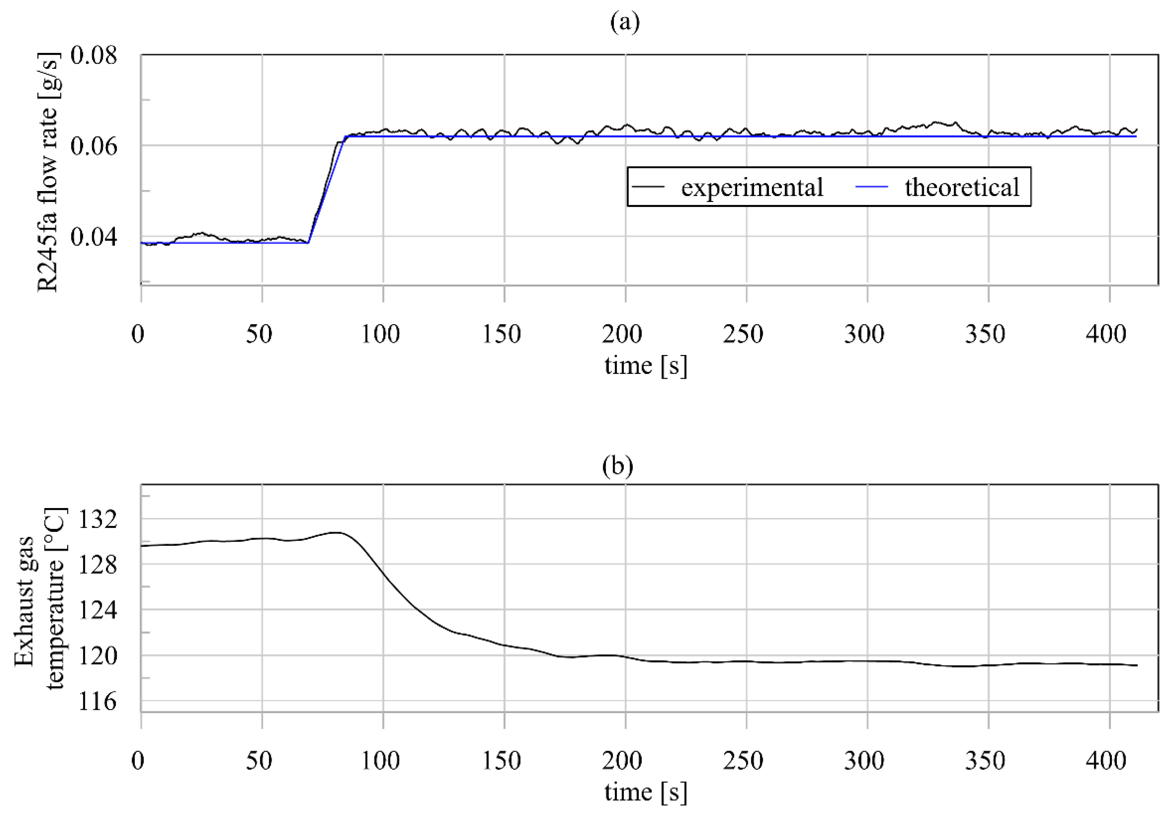
For the considered case, acting on pump speed variation, the step increase in R245fa mass flow rate was performed, keeping all the external parameters constant. In particular, the ICE torque was kept equal to 100 Nm and the ICE revolution speed to 3000 RPM, fixing the upper thermal stream. Consequently, the mass flow rate and the temperature of exhaust gas were constant and equal, respectively, to 0.09 kg/s and 340 °C. The analysis started from steady condition in which the flow rate of working fluid was 0.04 kg/s (
Figure 6). After 60 s following the start of the test, the mass flow rate provided by the pump saw a sudden variation of up to 0.062 kg/s (
Figure 6a). This was provided by increasing the pump revolution speed. It can be seen that the model is able to reproduce the experimental trend.
Figure 6 shows that the model correctly reproduces the mass flow rate variation caused by the increase in pump speed. This means that the model is capable of reproducing the control action released through the variation of pump speed.
When the mass flow rate increased, the temperature of the exhaust gas at the outlet of the evaporator followed a reduction of the first order from 130 °C to 120 °C (
Figure 6b). This is the only variation of the high thermal source being the mass flow rate and the inlet temperature of the exhaust gases equal to 0.1 kg/s and 340.4 °C, respectively. Both these values depend on the ICE operating condition defined by a Torque and ICE Speed, respectively, equal to 100 Nm and 3000 RPM.
Concerning the maximum pressure,
Figure 7a shows that in correspondence with the R245fa flow rate increase, the pressure sees an immediate growth, passing from 8.0 to 9.4 bar with a slight over oscillation expiring after 50 s. The maximum pressure, net to the pressure drop, coincides with the pressure at expander intake side. Indeed, when volumetric expanders are adopted, they define the maximum pressure of the plant according to their permeability [
27]. Permeability is defined as the ratio between the flow rate entering the machine and the pressure drop between expander sides. It depends on volumetric efficiency and expander revolution speed [
27]. Hence, the lower is the permeability, the higher the pressure drop across the expander.
R245fa flow rate variation has no effect on the minimum pressure level (
Figure 7b) which basically depends on the temperature of the cooling water at condenser (14–16 °C). As a matter of fact, it assumes a constant value over the whole observation time interval (450 s). The model is also capable of predicting this aspect as is confirmed by the low maximum deviation (3.3%) between experiments and theoretical values.
These results demonstrate that from a dynamical point of view, the expander presents a proportional behavior adapting the intake pressure (and consequently the maximum one) to the new value of mass flow rate.
A more complex behavior is shown by the temperature values, which are affected by the thermal inertia of evaporator. Indeed, observing
Figure 7c, the maximum R245fa temperature (measured at the outlet of the working fluid exiting the evaporator) sees a first-order decrease. In fact, after the step variation of mass flow rate, the temperature of working fluid reaches the novel steady-state condition after 340 s. This confirms that the dynamic behavior of evaporator plays a dominant role with respect to the other components.
It is important to observe that the difference between the inlet exhaust gas temperature (340 °C) and the outlet working fluid temperature (130 °C) is large. Nevertheless, the maximum temperature of working fluid cannot exceed 150 °C due to the temperature limit of the sealing material of the scroll expander.
The model also ensures a reliable prediction of the maximum pressure variation (
Figure 7a) reproducing the experimental trend with a good fidelity rate. This is demonstrated by the low average errors in steady-state condition before (AES1 = 7%) and after (AES2 = 2.3%) the transient period. In addition, the maximum deviation during transient period (MDT) is satisfying at values lower than 8.8%. The reliable reproduction of the maximum pressure means that the model is capable of replicating the effect of control action (mass flow rate variation) on the maximum pressure, which is commonly retained as the most important regulation parameter. Moreover, it also involves the correct representation of expander behavior which can be neglected with respect to the evaporator one. The dynamic behavior of evaporator plays a dominant role with respect to the other components; therefore, its correct assessment is crucial for model reliability. However, this model capability is demonstrated by the good agreement between experimental data and theoretical predictions reported in
Figure 7c. Indeed, the dynamic trend followed by the temperature is accurately predicted, also providing a reliable evaluation of the steady state before and after the occurrence of flow rate variation. AES1 and AES2 are equal, respectively, to 4 °C and 0.5 °C, whereas MDT is lower than 11 °C. Concerning the minimum temperature, this is strictly related to the minimum pressure, and the model predicts this value with the same error magnitude.
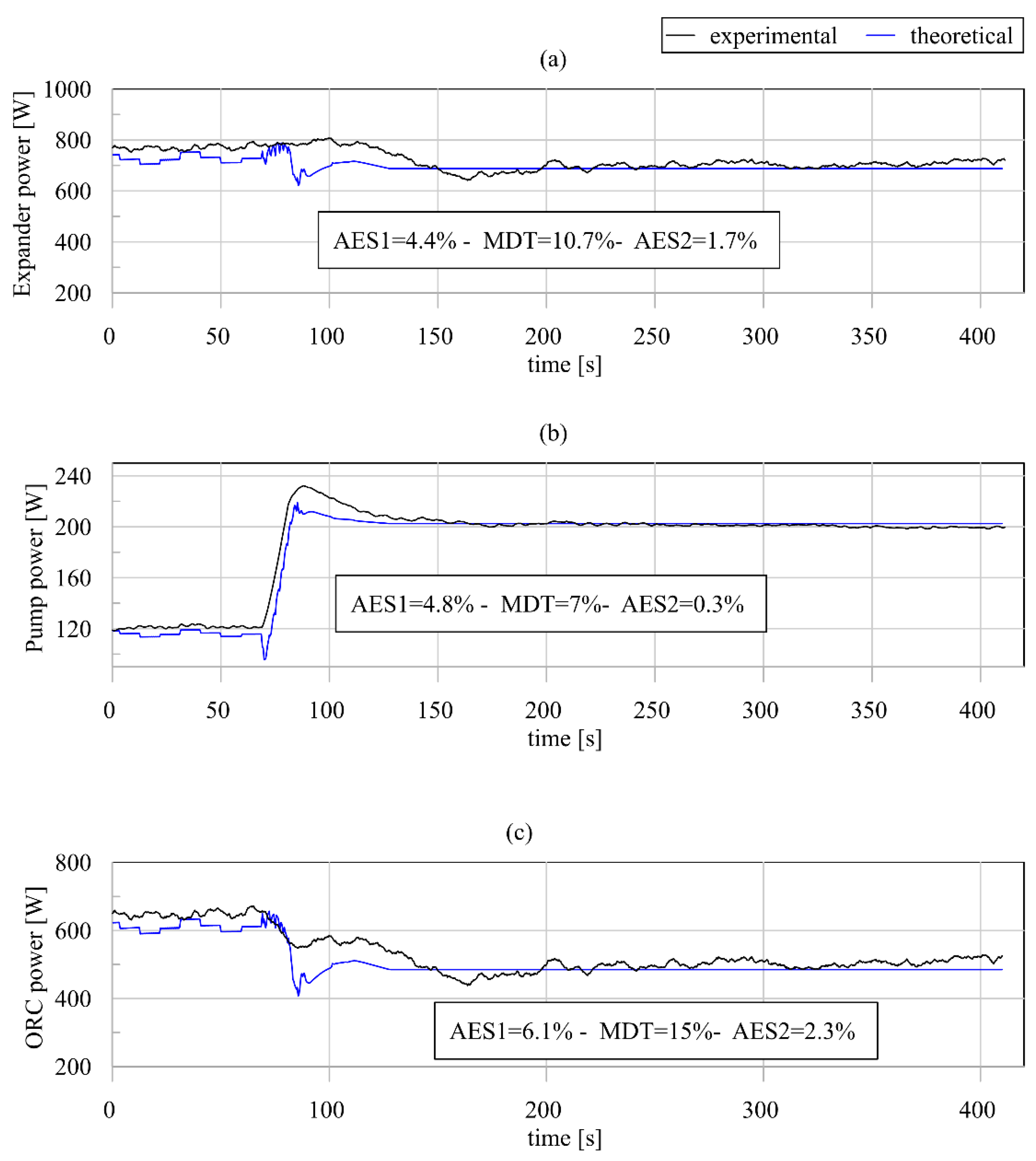
In
Figure 8a,b, the expander and pump powers are shown. After the sudden increase in the R245fa flow rate, the expander power decreases slightly despite the growth in the intake pressure (
Figure 8a). On the other hand, the pump power raises because it rotates at higher speed to elaborate higher mass flow rate (
Figure 8b). The combination of these effects leads to a reduction in the net power produced by the ORC plant, which passes from 600 to 500 W (
Figure 8c). Because of the correct representation of the pressure and temperature parameters, the model also provides reliable prediction in terms of expander, pump and ORC power. In
Figure 8a, the comparison between prediction and experimental data in terms of expander power shows a good reliability of the model with respect to catching the real transient behavior of the machine. AES1 and AES2 are equal, respectively, to 4.4% and 1.7%, whereas MDT is lower than 10.7%. This is explained by the fact that the pressure ratio at expander side is the most important parameter defining the expander power in the model.
In
Figure 8b, the pump power is reported; in this case, the good matching between the calculation and the measurements can also be observed. AES1 and AES2 in this case are equal, respectively, to 4.8% and 0.3%, whereas MDT is lower than 7%. In addition, the ORC power is correctly reproduced (
Figure 8c) by the model, both in terms of steady-state and transient behavior as shown by AES1, AES2 and MDT, respectively, equal to 6.1%, 2.3% and 15%.
Figure 9 shows the proportional decrease in superheating degree with mass flow rate. This is the main cause of the expander power decrease (
Figure 8a) with mass flow rate step enhancement (
Figure 6a). The superheating degree, indeed, reaches 3 °C when the steady-state condition is reached by the working fluid at expander intake. It is worth noting that the starting superheating degree was about 40 °C; this high value was set to overcome the possible incomplete vaporization of the working fluid during transient operating conditions.
Therefore, the capability of the model to accurately represent the experimental operating quantities in steady-state and transient conditions was demonstrated. This was possible due to the fact that each component was carefully modeled, as can be seen from the experimental validation results reported in
Table 5. For what concerns the pump, it presents a low maximum deviation between experimental and predicted values in terms of mass flow rate (−4.6%) and power required (1.5%). For what concerns the outlet pump temperature, a maximum deviation equal to 1.6 °C was observed.
All of the HRVG model ensures careful representation of the experimental behavior. Indeed, the maximum deviation between the experimental and predicted outlet temperature of R245fa is equal to 1.9 °C. Concerning the thermal power exchanged, a maximum deviation equal to 4.4% was noticed. It is worth to observe that the good accuracy in HRVG outlet pressure prediction (7.9%) is due to the goodness of the expander model as this component defines the plant maximum pressure according to its permeability. Indeed, the effect of the HRVG on the outlet pressure definition is only due to the pressure drop between the inlet and outlet sides and this contribution is limited with respect to the expander permeability. The expander model is also able to provide an accurate prediction of intake temperature whose maximum deviation is equal, respectively, to 2.8 °C. The model also ensures a good prevision of power with a maximum deviation of 4.6%. Concerning the condenser, the model provides a careful prediction of outlet pressure and temperature with maximum deviation equal, respectively, to 3.3% and 1.2 °C. Concerning the thermal power exchanged, the maximum deviation is equal to 5.7%.
The experimental analysis here developed provides the ORC dynamic response to the step variation of the mass flow rate provided by the pump. More complex variation of the mass flow rate of working fluid could be considered; however, step variation was chosen for two reasons. The first one is related to the fact that all the possible mass flow rate variation could be subdivided into multiple step variations. The second reason is that the best way to assess the ORC dynamic response is to consider the elementary cause variation. In fact, despite the simple cause, the ORC dynamic response is not straightforward. As shown by the experimental results, expander and pump present a fast dynamic response, whereas the response of heat recovery vapor generator is slower. Indeed, the sudden variation of mass flow rate and ORC maximum pressure is due to the fast dynamic response of the pump and expander, respectively. Otherwise, the first-order variation of ORC maximum temperature and superheating degree is due to thermal inertia of the Heat Recovery Vapor Generator. In addition, the condenser presents a significant thermal inertia, but its behavior was not assessed in this work due to its dependence on the low thermal source variation. Hence, the whole unit needs 250 s to reach the novel steady state due to the thermal inertia of the HRVG. Nevertheless, even if the ORC unit in this period works in transient conditions, it produces a significant amount of power (600–400 W). This is an important property of the plant, and it relies on the robustness of the expander to operate in transient condition.
5. Results
After the validation, the model has been used to investigate the effect of the pump revolution speed on the main cycle parameters and performance. The revolution speed of the pump primarily affects the mass flow rate of refrigerant in the ORC unit, which consequently impacts key variables such as superheating at the outlet of the HVRG, expander performance and thermodynamic conditions at the condenser outlet. It represents one of the most effective and easy-to-control parameters of the system to adjust the performance and operation of the unit to the transient waste heat load available at the outlet of the engine.
To understand the impact of such control variable, three dynamic simulations have been carried out, varying the revolution speed of the pump/mass flow rate and keeping the boundary conditions of the model, such as temperature and mass flow rate of heat and cooling source, constant. In particular, the ICE torque was kept equal to 100 Nm and the ICE revolution speed was kept equal to 3000 RPM. Consequently, the mass flow rate and the temperature of exhaust gas are constant and equal, respectively, to 0.09 kg/s and 340 °C.
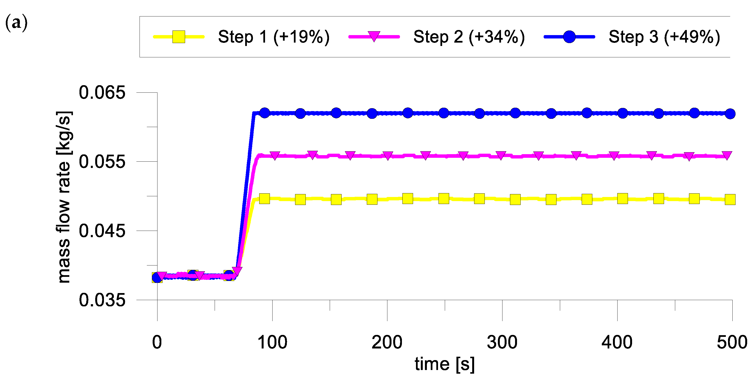
In the three simulated cases, a step of revolution speed at the pump has been imposed. In particular, the revolution speed of the pump has been increased from the initial value of 246 RPM to the final one of 293 RPM (an increase of 19%, Step 1), 329 RPM (an increase of 34%, Step 2) and 366 RPM (an increase of 49%, Step 3). The last case is the one used to validate the model in
Section 4.
Figure 10 shows the outcomes of the simulations.
Figure 10a illustrates the increase in mass flow rate of the refrigerant following the three-step increase in the pump revolution speed. The maximum mass flow rate increase occurs in the third case, where the mass flow rate of refrigerant raises from 0.038 kg/s up to 0.062 kg/s with a time constant of 2.2 s. Lower pump revolution speed steps lead to lower final mass flow rate values of 0.050 kg/s and 0.055 kg/s (Step 1 and Step 2, respectively, in
Figure 10a).
The maximum pressure in the system also rises following the increase in refrigerant mass flow rate processed in the system. Given the permeability of the scroll expander, higher flow rates lead to increased pressure ratio across the machine, with a consequent higher pressure at the expander intake since the minimum pressure of the system (the one at expander exhaust) is fixed by the constant cooling conditions (as showed in
Figure 10c). However, a saturation effect can be noticed, since a 49% and 63% increase in mass flow rate in the second and third step, respectively (
Figure 10a), leads approximately to the same maximum pressure rise (from 7.0 bar up to 9.4 bar as shown in
Figure 10b).
This is explained by the fact that in the third case, the superheating degree is significantly lower with respect to the other cases. In fact, if superheating degree variations become significant, the deviation of ORC maximum pressure from the linear growth with mass flow rate increases. This is due to the higher amount of refrigerant that must be vaporized when the mass flow rate is increased substantially. This higher thermal load required by the refrigerant improves the heat recovered, but creates a pinch point at the evaporator, which consequently limits the rise of pressure at the evaporator outlet and then at the expander intake.
As a consequent result, the maximum temperature of the cycle also drops as shown in
Figure 10d, and so does the superheating at the expander inlet. In particular, while the first step leads to a temperature drop of 16 °C, the second and third steps cause a temperature decrease in temperature equal to 29 °C and 43 °C, respectively (
Figure 10d).
Figure 10e shows, on the contrary, that the minimum temperature of the cycle at the expander exhaust remains almost unchanged since the cooling load has been constant during the simulations. The maximum variation of such temperature equals to 2 °C for a 63% rise in refrigerant mass flow rate (
Figure 10e).
From a transient point of view, the results in
Figure 10 confirm that the time constant of the temperatures, depending mainly on the mass of the heat exchangers, are higher than those of pressure, more related to the volumetric machines. For the maximum cycle temperature, the time constant is 12 s, and the pressure constant is 8 s.
Both temperature and pressure at the expander intake show a good dynamic response to a variation of the pump revolution speed. The results also demonstrate that the pump revolution speed has good controllability on temperature at the outlet of the evaporator, causing a variation of 32% after a step revolution speed change of 49% (
Figure 10). A reduced controllability is shown on the refrigerant pressure at the expander intake for huge mass flow rate variation, which showed a nonlinear behavior caused by the severe reduction of superheating degree. Anyway, if the mass flow rate increase does not provide too low values of superheating degree the relation between mass flow rate and ORC maximum pressure is linear
Regarding the ORC performance,
Figure 11 shows the power consumption of the pump, the power generated by the expander, and the net output of the ORC unit. In
Figure 11a it is possible to observe that, in response to the increased mass flow rate of refrigerant processed, the pump power consumption increases accordingly, rising from 95 W to 158 W, 173 W and 219 W in the first, second and third steps, respectively (
Figure 11a).
In particular, the third step results in a higher rise in power consumption due to the increased pressure drops in the circuit following the higher mass flow rate of refrigerant.
The expander output shows a nonlinear behavior with respect to the mass flow rate of refrigerant. In the first step, where the mass flow rate changes from 0.038 kg/s up to 0.050 kg/s (
Figure 10a), the expander power output increases from 750 W to 835 W (
Figure 11b). The higher pressure at the intake and the slightly increased mass flow rate have indeed a positive effect on the expander volumetric efficiency and therefore on power output. Furthermore, in this case, the decrease in superheating at the inlet of the machine is not so pronounced, being equal to 10 °C (
Figure 10d); this leads to a less pronounced drop in density and higher work per unit of fluid processed.
For larger step increases in the mass flow rate, the detrimental effect of the lower superheating becomes predominant and leads to lower efficiencies of the expander and consequent lower produced power.
Figure 11b shows that, in fact, for a step increase of 34% and 49% of the pump revolution speed, the expander power output rises from 750 W to 766 W and 675 W, respectively. In the third case, the superheating drop becomes so relevant that it actually leads to a decrease in the expander performance.
This trend can be noticed in the ORC net power output as well, where a small mass flow rate step increase leads to an improved performance, from 640 W up to 680 W (
Figure 11c), while higher rises cause a reduction in net power output, which equals 610 W and 460 W when the mass flow rate is increased to 0.055 kg/s and 0.063 kg/s, respectively (
Figure 10a and
Figure 11c).
Therefore, it can be seen in
Figure 11 that the increase in mass flow rate does not always produce a beneficial effect on ORC performance. Indeed, for a given thermal power available at the evaporator, when the mass flow rate is enhanced, there are two opposite effects. The former is related to the fact that the ORC maximum pressure tends to grow according to the expander permeability. This leads to a higher net power output as the expander pressure ratio grows, even if the minimum pressure in the unit remains quite constant (
Figure 9c). Nevertheless, the second effect produced by the mass flow rate increase is the reduction of superheating degree. If this reduction is too severe, the expander performance diminishes (
Figure 11a). Indeed, as reported in
Table 6 for Step 3 case, if the mass flow rate increase is too high (+63%), the heavy reduction in superheating degree from 47 °C to 6 °C involves the expander efficiency decrease from 50% to 29%. This is because, despite the mass flow rate increase seeing a growth of 63% with respect to the starting conditions, the increase in the expander intake pressure (and consequently the expansion ratio) is equal to (+34.4%). This value is close to that obtained in Step 2 case, where an increase in the intake pressure of 32% is achieved with an enhancement of mass flow rate equal to 45%. Hence, a severe superheating degree reduction partially erodes the benefits of pressure increase provided by the mass flow rate enhancement.
Moreover, the negative effects also impact the ORC unit efficiency (17). Indeed, the mass flow rate enhancement produces a growth of power required by the pump. The most critical point is Step 3 case, where the growth of mass flow rate is (+63%), does not produce a significant increase in expansion pressure ratio, so the expander efficiency decreases. Moreover, higher mass flow rate produces larger power required by the pump with higher impact on expander power as shown by the increase in BWR from 16% to 33%. This reflects on the ORC efficiency, which in case of Step 3 diminishes up to 1.9% with respect to the starting condition (3.2%).
Therefore, the present study presents a theoretical and experimental assessment of the ORC transient performance when the main regulating parameter is varied. The theoretical and experimental analysis ensures the understanding that the control action exploited varying of the mass flow rate provided by the pump produces a fast variation on ORC maximum pressure and consequently on expander pressure ratio. Indeed, the minimum pressure depends quite exclusively on the low thermal source conditions. On the other hand, the working fluid temperature follows a typical first-order dynamic trend due to the thermal inertia of Heat Recovery Vapor Generator. Nevertheless, even in transient conditions, the ORC-based power unit produces a significant power because of the robustness of the scroll expander. Despite the fact that the theoretical and experimental analysis ensures to understand the dynamic behavior of the ORC unit, the regulation strategy is limited by the uncontrolled expander speed. Indeed, if the expander speed is regulated, an important degree of freedom is added to the regulation phase. In fact, the variation of expander speed ensures to set the expander intake pressure for a given mass flow rate provided by the pump. Hence, a further development of the present study is the analysis of the ORC-based power unit when the expander speed is externally controlled.


 ,
, 


