1. Introduction
Currently, permanent magnet synchronous motor (PMSM) drive systems are widely used in industrial production, household appliances, and transportation [
1,
2,
3,
4,
5]. Bulky electrolytic capacitors are used to decouple the drive system power and keep the DC-link voltage stable, which can ensure high motor performance under various operation conditions. However, due to their short life span and poor reliability, electrolytic capacitors have become the short plate of motor drive systems [
5,
6].
ECL motor drive systems adopt APDCs with small film capacitors to replace bulky electrolytic capacitors to absorb the grid ripple power, which have received more attention due to their high reliability and long span life [
7,
8]. However, there is a larger DC-link ripple voltage due to the significant reduction of the decoupling capacitor. This ripple voltage degrades the performance of ECL drive systems [
9,
10,
11,
12]. Therefore, it has become an interesting and challenging topic for APDCs to achieve small DC-link ripple voltage under various operation conditions.
Under steady-state conditions, it has been shown that existing ECL motor drive systems have little DC-link ripple voltage, which helps the grid current meet harmonics standards, such as IEC61000-3-2, and PMSMs have high stable performance with low-speed ripple and low torque ripple [
13,
14]. However, under dynamic operation conditions, the DC-link ripple voltage changes dramatically, which sharply deteriorates the performance of ECL drive systems. The reason for the sudden change in the DC-link voltage is that the grid power regulation of ECL drive systems lags behind motor power change, and the extra motor power must be provided by the small decoupling capacitor [
15].
There are some efforts to suppress the DC-link voltage ripple under dynamic operation conditions. In [
16], the motor dynamic response process is deliberately extended to reduce the DC-link voltage ripple. Unfortunately, it inevitably degrades the dynamic performance of motors. Therefore, how to improve the response speed of the grid power has become the focus of the ECL drive system. In [
17], a power loop is added to the DC-link voltage controller to improve the speed of grid power response to load changes. However, due to the small damping characteristic of ECL drive systems, there is a large DC-link voltage ripple when the load changes drastically. In [
18], the instantaneous amplitude of DC-link voltage is obtained through
αβ-dq coordinate transformation and applied in the control of grid power to suppress the DC-link voltage ripple. However, there is a quarter grid cycle delay in constructing the quadrature variables by single-phase coordinate transformation, which reduces the fast regulation performance of the grid power control.
In recent years, model predictive control (MPC) has received extensive attention in the field of motor drive because of its good dynamic performance [
19,
20,
21]. In [
22], the cost function is designed based on the DC-link voltage ripple, and the constraint relations of
id,
iq, and
ig are constructed to suppress the DC-link ripple voltage under various working conditions. Similarly, the ripple power of the decoupling capacitor is combined with MPC in [
23,
24], where the grid power is predicted to improve the motor dynamic performance. In [
25], a current predictive model is applied in dual-buck APDC, which controls the decoupling capacitor voltage through the inductor current of APDC. However, these methods only optimize the individual performance of APDCs and cannot improve the overall performance of ECL drive systems.
This paper proposes a model predictive current control (MPCC) strategy based on motor power change. Its main purpose is to improve the overall performance of ECL drive systems based on the suppression of DC-link ripple voltage under dynamic operation conditions. The proposed MPCC takes asymmetric split-capacitor APDC as an example [
15]. A grid current predictive model is established, where the motor power is introduced. The model improves the ability of the grid current to quickly track motor power changes under dynamic operation conditions. Meanwhile, the minimum error of grid current and motor power change is combined as a cost function to ensure the accuracy of the grid current track. In addition, the predictive model of the decoupling inductor is established, and the inductor current error is taken as the cost function, which effectively suppresses the DC-link voltage ripple even under dynamic operation conditions. As a result, the motor has a good dynamic performance and the grid power quality can satisfy the requirement of IEC61000-3-2.
In
Section 2, the operation modes of the asymmetric split-capacitor APDC topology will be described. The relationship between the DC-link voltage ripple and motor power will be analyzed in
Section 3. In
Section 4, details of MPCC with motor power changes will be proposed. Moreover, the performance of the proposed MPCC will be assessed by using the experimental results. Finally, the conclusions will be drawn in
Section 6.
2. Operating Principle of Asymmetric Split-Capacitor APDC
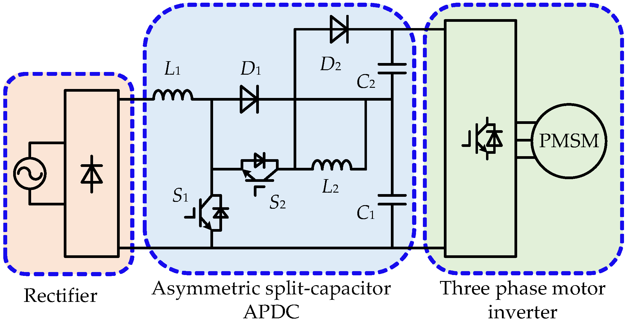
Figure 1 shows the topology of the ECL motor drive system studied in this paper [
16], where asymmetric split-capacitor APDC is composed of a Boost circuit and a ripple power processing circuit. In the ECL motor drive system, the DC-link is composed of unequal capacitors C
1 and C
2 connected in series. The Boost circuit consists of inductor L
1, diode D
1, power switch S
1, and film capacitor C
1. The ripple power processing circuit consists of inductor L
2, diode D
2, power switch S
2 and film capacitor C
2.
In this APDC, the average voltage of C1 remains unchanged under dynamic operation conditions and the ripple voltage changes with the motor power. The ripple power processing circuit controls the voltage of C2 to be complementary to the voltage of C1 to achieve ripple voltage suppression on the DC-link.
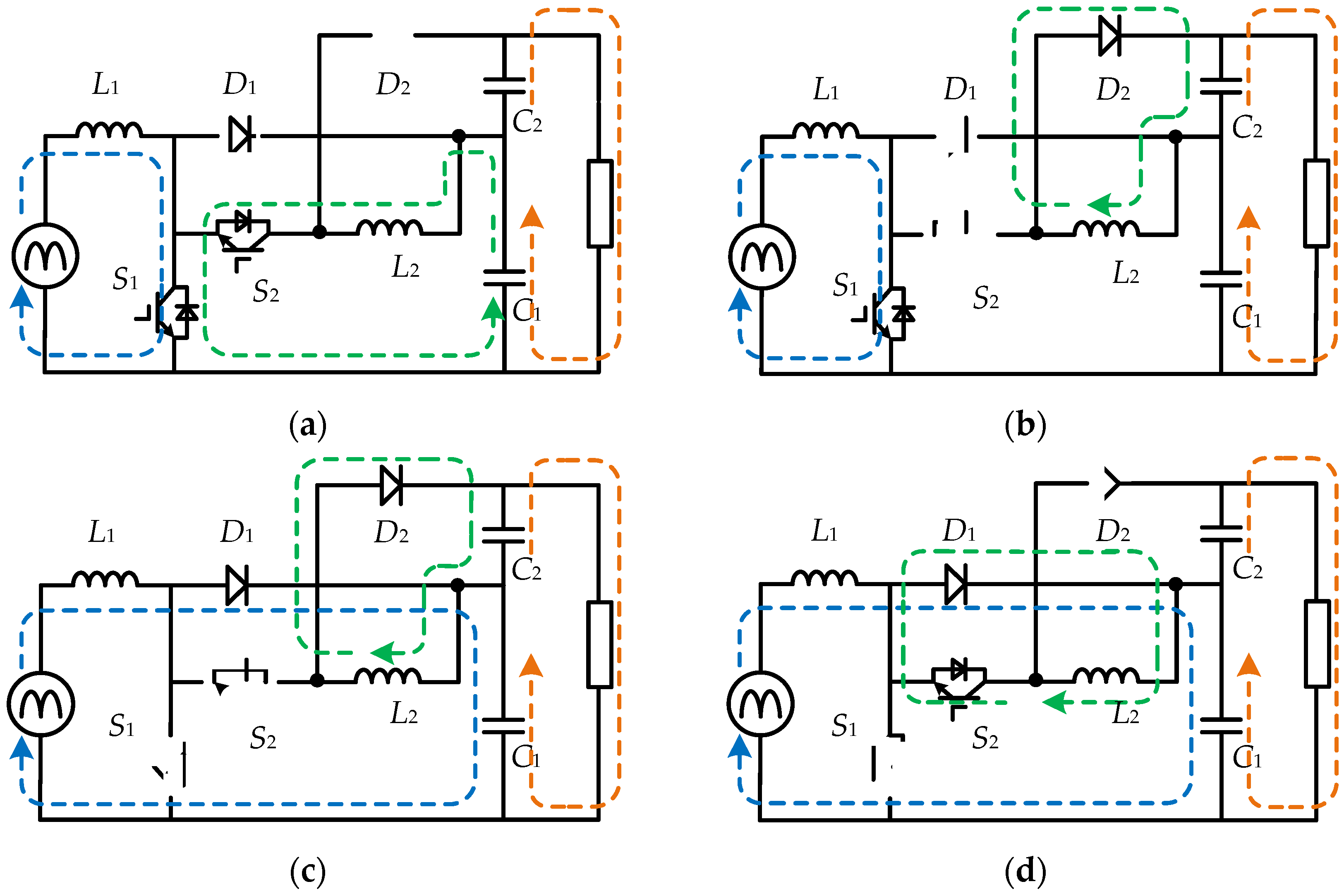
Figure 2 shows the four operation modes of asymmetric split-capacitor APDC in one operation cycle. S
1 and S
2 are respectively used to control the grid power quality and to suppress DC-link voltage ripple. When S
1 is on-state, L
1 stores the grid ripple power, and the current of L
1 increases. When S
1 is off, the grid and L
1 in series supply power to the back-end converter, and the current of L
1 decreases. Therefore, the grid current quality can be controlled by S
1. Meanwhile, the average voltage of C
1 can be controlled. When S
2 is on, C
1 charges L
2, and the voltage of C
1 decreases. When S
2 is off, L
2 supplies power to C
2. Therefore, the voltage of C
2 can be controlled by S
2. Finally, the voltages of C
1 and C
2 are complementary, and the DC-link voltage ripple can be suppressed by S
1 and S
2.
In the APDC shown in
Figure 1, the instantaneous voltages
uC1 and
uC2 of C
1 and C
2 are
where
UC1/UC2 are the average voltages of
C1/C2,
K1/
K2 are the ratios of instantaneous power of
C1/C2 and input instantaneous power of APDC,
PM is the motor power,
ω is the angular frequency of the grid voltage.
According to (1), if there is
the DC-link voltage ripple of the asymmetric split-capacitors APDC is always zero. Therefore, the APDC has high robustness to capacitance changes of
C1/C2. In addition, the current
iL2 of
L2 and
uC2 have [
15]
(3) shows that uC2 can be controlled by iL2.
3. Dynamic Characteristics of Asymmetric Split-Capacitor APDC
It is assumed that the grid voltage and current are in the same phase, the grid power is expressed as
where
pin and
Pin are the instantaneous input power and average power of the ECL drive system, respectively.
Uin and
Iin are the average voltage and average current of the grid, respectively. (4) shows that the input power of ECL drive systems consists of a DC component
PM and an AC component
pr (
PMcos(2
ωt)). For conventional drive systems,
pr is passively absorbed or released by bulky electrolytic capacitors. For ECL motor drive systems,
pr is actively absorbed or released by APDCs.
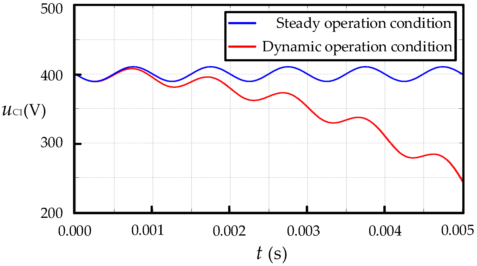
(1) and (2) show that the DC-link voltage ripple can be effectively controlled within small scope under steady operation conditions. However, under dynamic operation conditions, the DC-link voltage characteristics of ECL drive systems are obviously different from that of the steady operation condition or traditional drive system due to the significant reduction of the decoupling capacitor. To simplify the analysis, it is assumed that the motor power varies linearly
where
pM is the motor instantaneous power,
t is the adjustment time of the dynamic process, and
k is the coefficient of motor power change, which reflects the response speed of the motor. Combined with (4) and (5), there is
Under existing control strategies, the grid power lags the motor power change. According to (5) and (6), the ripple power of APDC under dynamic conditions is
(7) shows that the ripple power buffered by APDCs under dynamic operation conditions includes not only the grid ripple power but also the newly added motor power. The ripple power of APDC equals the sum of split-capacitor power
Taking
C1 as an example, the power of
C1 can be further obtained from (8)
where
m is the ratio of the power of
C1 to the total ripple power of the APDC. It can be further obtained by combining (8) and (9)
Integrating both sides of (10) to time, the voltage of
C1 can be expressed as
Figure 3 shows the waveforms of
uC1, which shows that when the grid power lags the motor power change, the voltage of
C1 will drop rapidly and sharply.
4. MPCC Strategy Based on Motor Power Change
To effectively suppress the DC-link ripple voltage of the ECL drive system under dynamic conditions, an MPCC strategy based on motor power change is proposed which can control the grid power to quickly and accurately track the motor power change. In addition, combined with the cost function of minimum current error, the proposed MPCC can comprehensively optimize the grid power quality, the DC-link voltage ripple, which achieves the high-performance operation of ECL drive systems.
4.1. Current Predictive Model of The APDC
According to the theory of KVL and
Figure 2, the state equations of
iL1 of asymmetric split-capacitor APDC can be expressed as
where
uin is the input voltage of APDC. Similarly, the state equations of
iL2 can be expressed as
The predicted value
iL1(
k + 1) of
iL1 is obtained after Euler discretization of (12)
where
TS is the sampling period,
uin(
k) and
uC1(
k) are the input voltage of APDC and the voltage of
C1 respectively at sampling point
k. Similarly, the predicted value
iL2(
k + 1) of
iL2 can be expressed as
where
uC2(
k) is the voltage of
C2 at sampling point
k.
4.2. Control Strategy of APDC
To implement the high-performance operation of the ECL drive system, it is necessary to adjust the grid input power
pin* synchronously with the motor power
PM under dynamic conditions. Accordingly,
Pr* buffered by the APDC is zero under dynamic conditions
where
Pr* is the average of the grid ripple power
pr.
In this case, the grid power satisfies
where
Pin(
k) is the average grid power at
k,
Pin(
k + 1) is the predicted average grid power at
k + 1 and Δ
PM is the motor power difference between
k and
k + 1. The average grid power
Pin is expressed as
Iin is the average grid current. It can be obtained by combining (19) and (20)
where
IL1(
k + 1) is the average grid current at
k + 1. Since
iL1 is the same frequency and phase as the grid voltage,
iL1(
k + 1) can be obtained by (21) multiplying by
.
Since the sampling period is small enough, Δ
PM can be expressed as
Combined with (22) and (23), the grid reference current
iL1*(
k + 1) can be obtained
(24) shows that iL1*(k + 1) can be quickly adjusted according to the motor power, which overcomes the problem that the grid reference current lags the motor power change and avoids the large DC-link ripple voltage.
To further improve the accuracy of grid current tracking under dynamic operation conditions, Δ
PM is introduced into the cost function of MPCC. The corresponding cost function
g1 is defined as
The current predictive model (15) that minimizes the cost function g1 is chosen to control S1 so that iL1(k + 1) precisely tracks iL1*(k + 1). Therefore, the grid power is quickly and accurately adjusted according to motor power change under dynamic operation conditions, which avoids the decoupling capacitor to absorb or release ΔPM and large voltage changes in the DC-link.
(3) shows that
uC2 and
uC1 can be complementary by controlling
iL2 to effectively suppress the DC-link ripple voltage. Therefore, the corresponding cost function
g2 is constructed
where
iL2* is the given current of L
2. Corresponding to the different states of S
1, the
iL2 current predictive model (16) or (17) is chosen to minimize the cost function
g2 and the on-off state of S
2 is selected, which makes
iL2 track precisely
iL2*. Therefore, high precision complementarity of
uC1 and
uC2 is achieved and the DC-link voltage ripple is effectively suppressed.
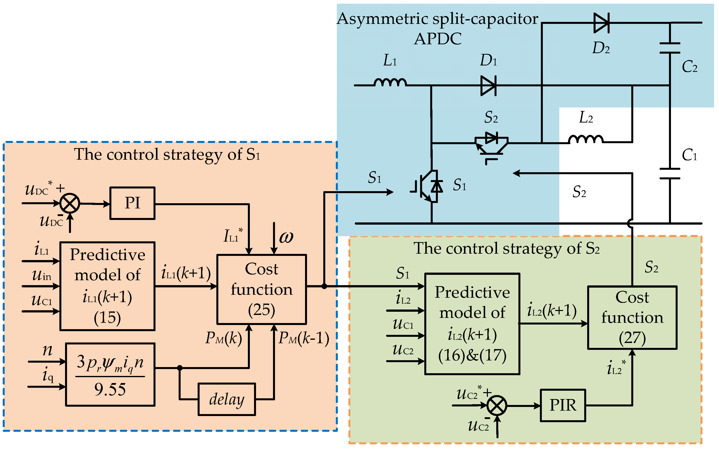
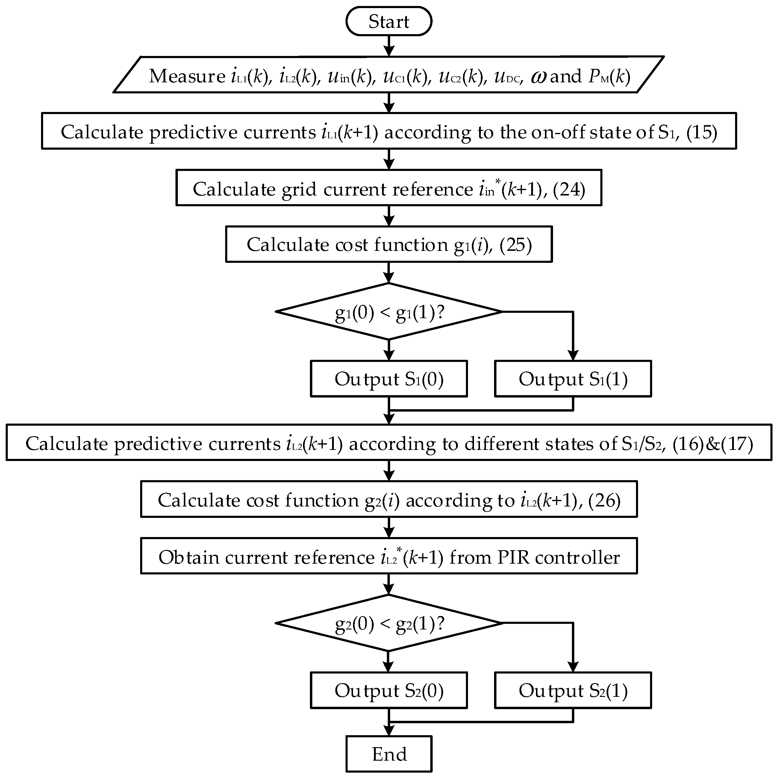
The proposed MPCC control strategy is shown in
Figure 4, and the flow diagram is shown in
Figure 5, where
iL2* is acquired by a PIR controller combining PI control and proportional resonance (PR) control. The detailed operation principle of the MPCC is as follows:
The voltage, current, phase of the grid, and motor power are obtained by sensors or signal process circuits. And then, the predictive grid currents are obtained by (15) according to the on-off state of S1.
ΔPM is substituted into (24) to calculate iin*(k + 1).
(15) and (24) are substituted into the cost function (25), and the switching state of S1 that minimizes the cost function is selected.
According to the different states of S1/S2, uC1, uC2 and iL2 are used to calculate the predictive current iL2(k + 1) according to (16) or (17), respectively.
iL2(k + 1) and iL2* are substituted into the cost function (26), and the switching state of S2 that minimizes the cost function is selected.
5. Experimental Result
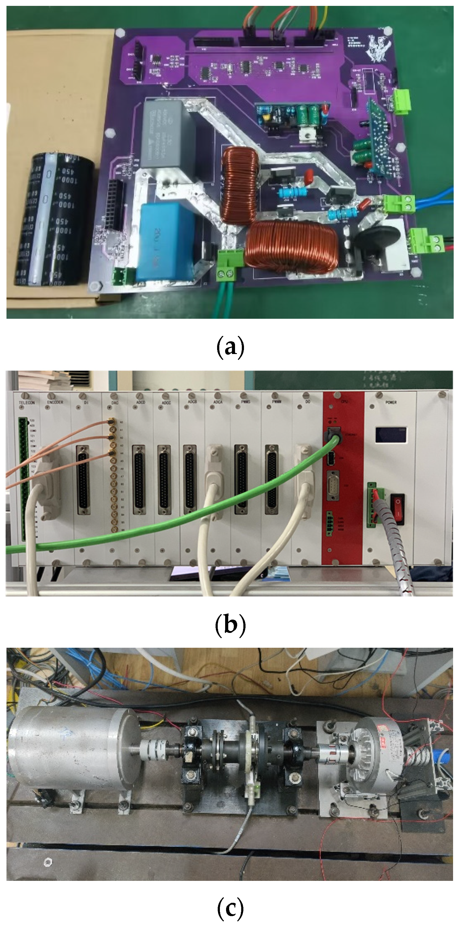
To verify the effectiveness of the proposed MPCC, an experimental platform was built, as shown in
Figure 6a. The hardware-in-the-loop simulation platform Rtunit was used to implement the control strategy. The key parameters of the ECL drive system are shown in
Table 1. A 0.5 kW magnetic powder brake acts as the load. The average grid voltage is 110 V and the angular frequency is 314 rad/s. The DC-link voltage is set to 300 V, the average voltages of C
1 and C
2 are set to 200 V and 100 V, and the maximum voltage ripple is set to 50 V. The speed and torque of PMSM were respectively obtained by photoelectric encoder Tamagawa TS5314N512-2500C/T and torque sensor JN338. The voltages of C
1 and C
2 were obtained by a voltage divider resistor and an isolation amplifier, and hall sensors ACS712 were used to obtain the current of L
1 and L
2. Two IGBTs IKA15N60T of 600 V rating voltage and 15 A rating current were used for the proposed APDC. Two galvanic isolated drivers 2ED020I12-F were used to provide drive current for two IG-BTs.
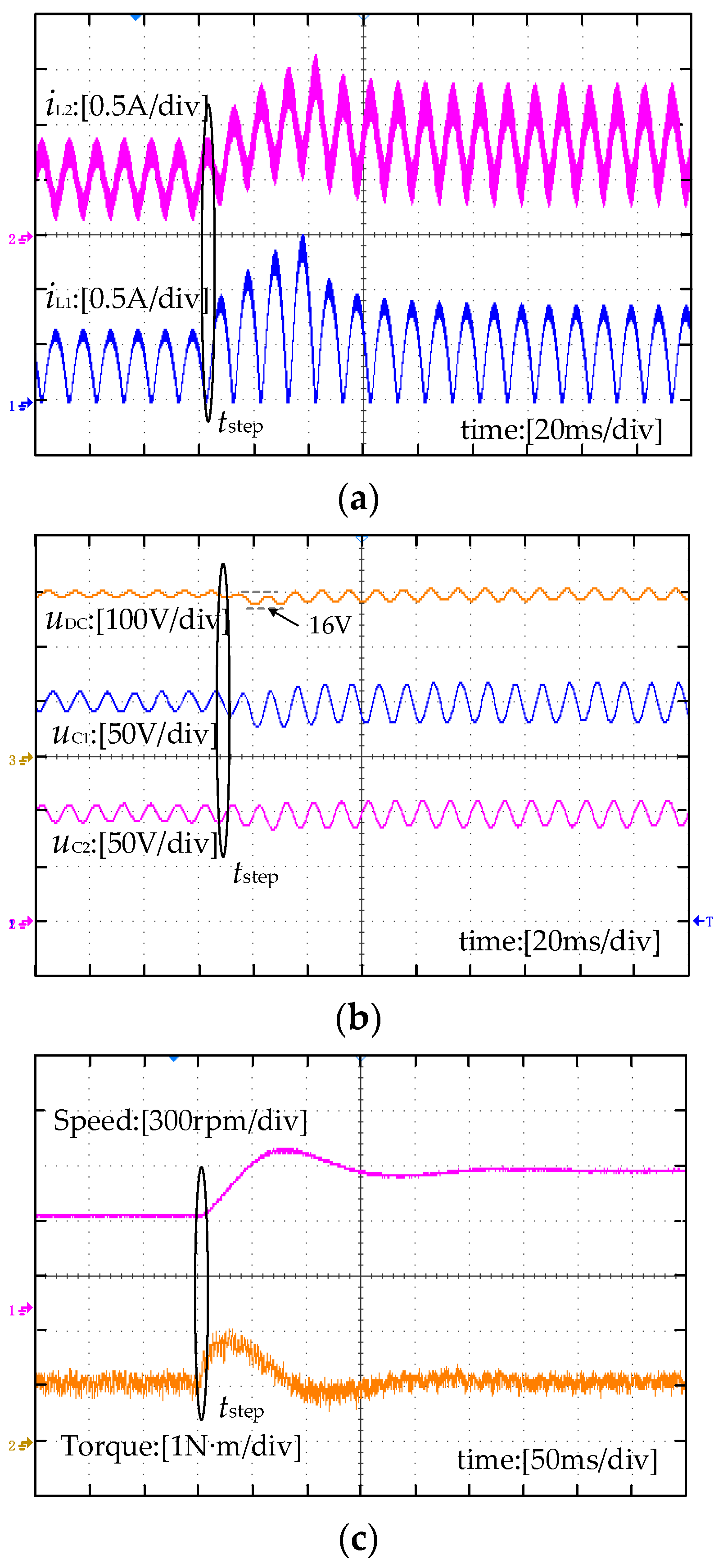
Figure 7 shows the experimental waveforms of the ECL drive system based on asymmetric split-capacitor APDC under variable speed operation conditions. In this experiment, the load is 1 N∙m, the initial motor speed is 500 rpm, and the given speed changes from 500 rpm to 800 rpm at
tstep.
Figure 7a shows that when the given speed changes,
iL1, and
iL2 can quickly increase according to the motor power change, which avoids a large energy release from the two split capacitors. As a result, the ripple voltages of
uC1 and
uC2 increase only slightly when the motor speed increases. Meanwhile, the voltages of
C1 and
C2 are still complementary. Therefore, the drop in the DC-link voltage is controlled within 20 V and the DC-link voltage quickly returns to the rated voltage within 100 ms, as shown in
Figure 7b. The waveforms of motor speed and torque in
Figure 7c show that the proposed MPCC make the PMSM operate at 800 rpm within only 200 ms.
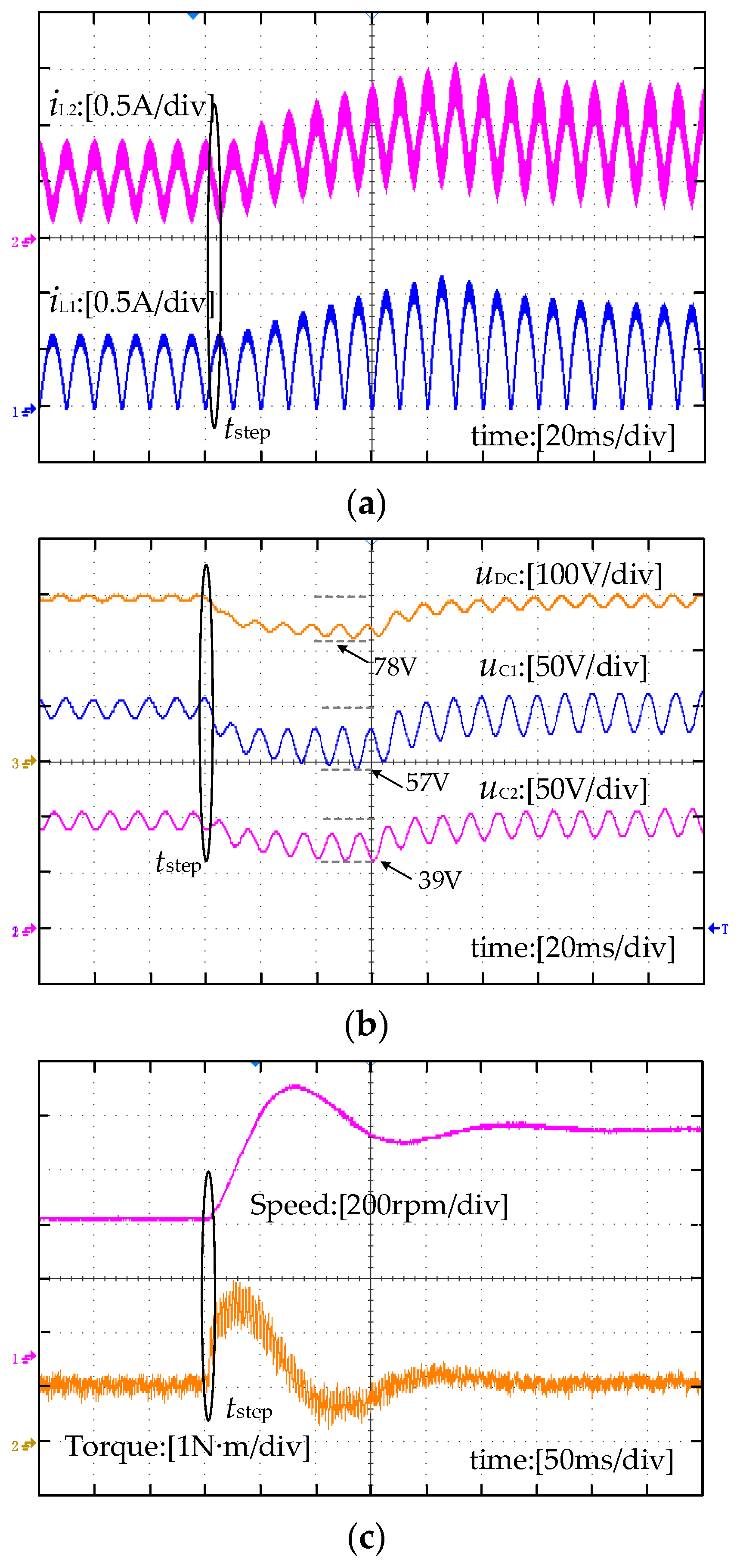
Figure 8 shows the experimental waveforms of the test ECL driver under the traditional PI control, which has the same experimental conditions as
Figure 7. The experimental waveforms show that the grid current obviously lags the motor speed change, which results in the maximum drop voltages of 57 V and 39 V for
uC1 and
uC2, respectively, and 78 V for the DC-link voltage. Meanwhile, the ECL motor drive system with the traditional control takes 200 ms to restore the drop voltage of the DC-link to the set value and takes 350 ms to reach the given 800 rpm, which is significantly longer than that of the proposed MPCC.
Figure 9 shows the experimental waveforms of a traditional motor driver with a 1100 μF DC-link capacitor, which has the same experimental conditions as
Figure 6. In this experiment, the maximum drop of DC-link voltage is 30 V. The conventional motor drive system takes 120 ms to restore the drop voltage of the DC-link to the set value and takes 210 ms to reach the given 800 rpm.
It can be seen from
Figure 7,
Figure 8 and
Figure 9 that compared with the traditional control method, the proposed MPCC can significantly improve the ECL drive system performance of DC-link voltage suppression and motor fast response. In addition, the ECL drive performance with the proposed MPCC is consistent with the traditional drive system with a bulky DC-link capacitor.
Figure 10,
Figure 11 and
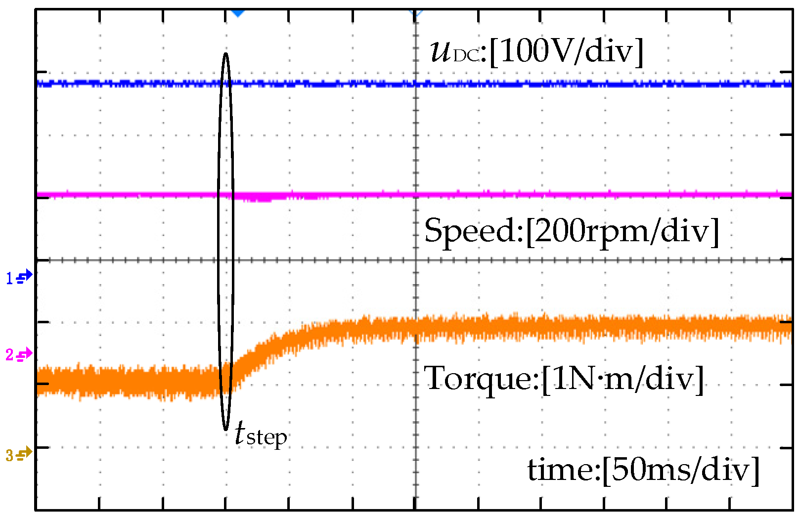
Figure 12 show the experimental waveforms of three different drive systems under variable load operation conditions. The experimental conditions are as follows: the given motor speed is 500 rpm and the load torque changes from 1 Nm to 1.5 Nm at
tstep.
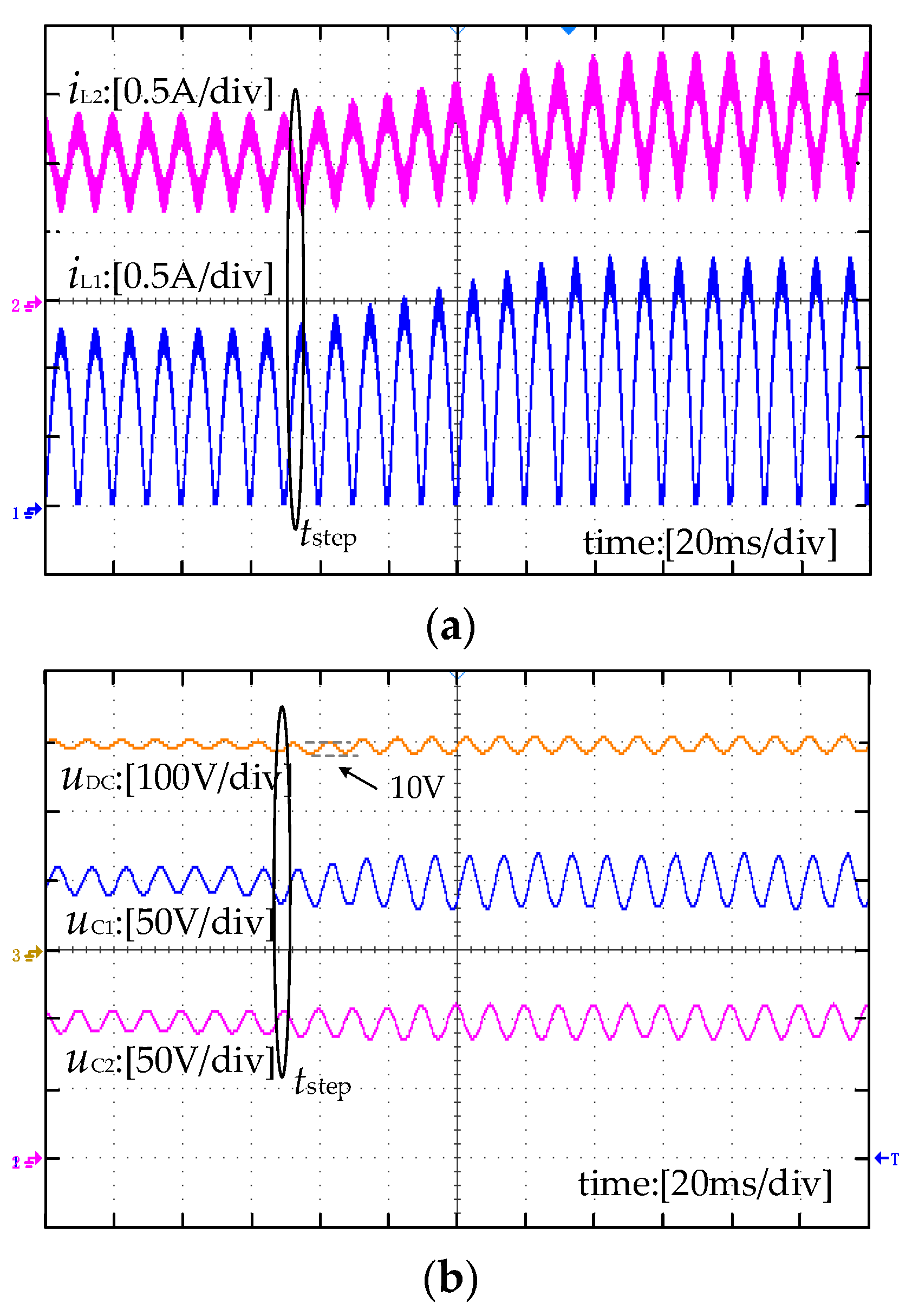
Figure 10 shows the experimental waveforms of the ECL driver based on asymmetric split-capacitor APDC under the proposed MPCC.
Figure 10a shows that the proposed MPCC can adjust quickly
iL1 and
iL2 when the load changes rapidly. In this experiment, the ripple voltages of
uC1 and
uC2 only increase slightly and the average voltages of
uC1 and
uC2 keep stable. Therefore, the maximum drop voltage of the DC-link is less than 10 V and the DC-link voltage returns to the rated voltage within 80 ms, as shown in
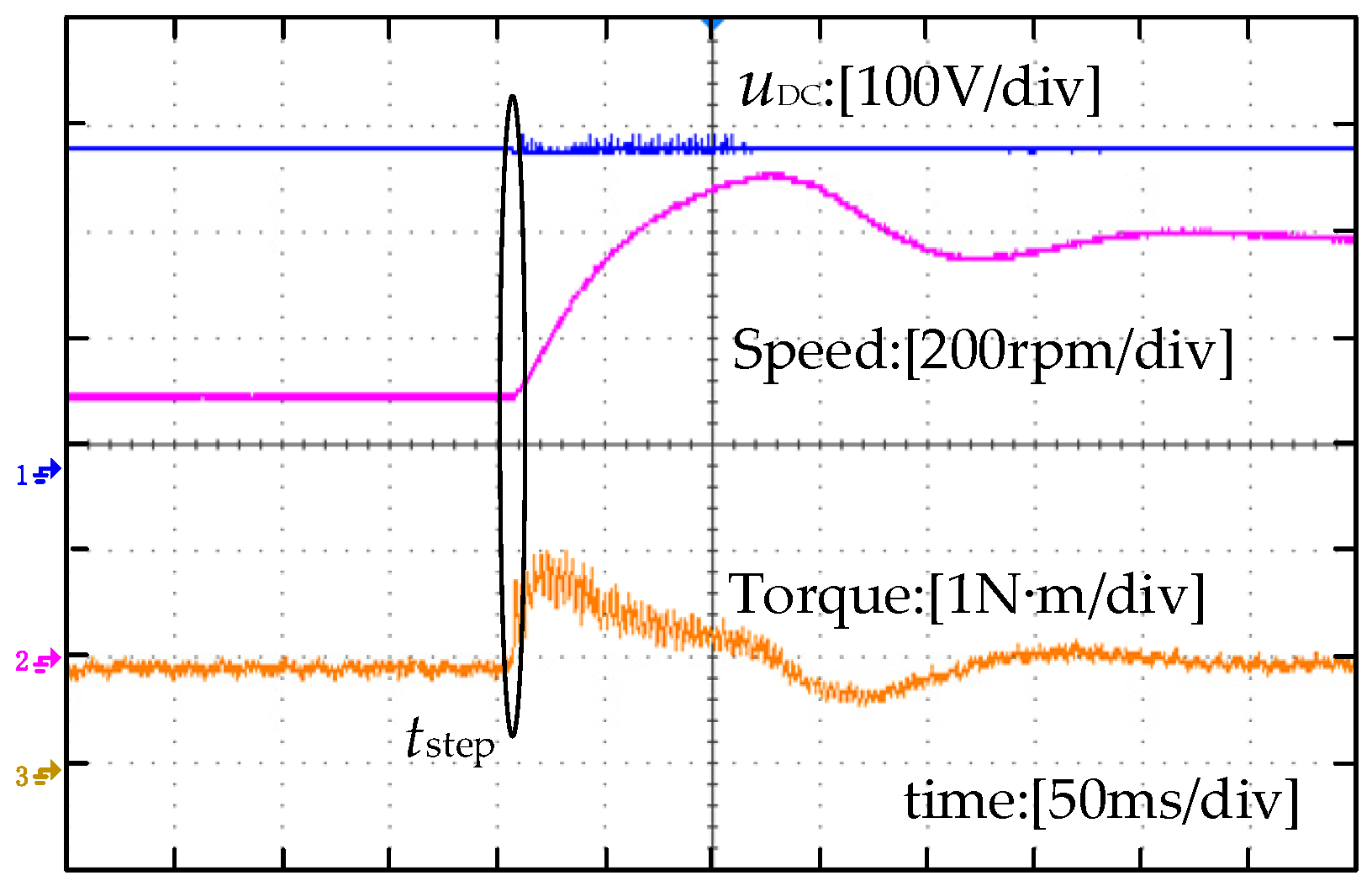
Figure 10b. Since there is very little ripple voltage on the DC-link of the ECL drive system, the motor only has a speed drop of 10 rpm and the recovery time is 50 ms under the load-step operation condition, as shown in
Figure 10c.
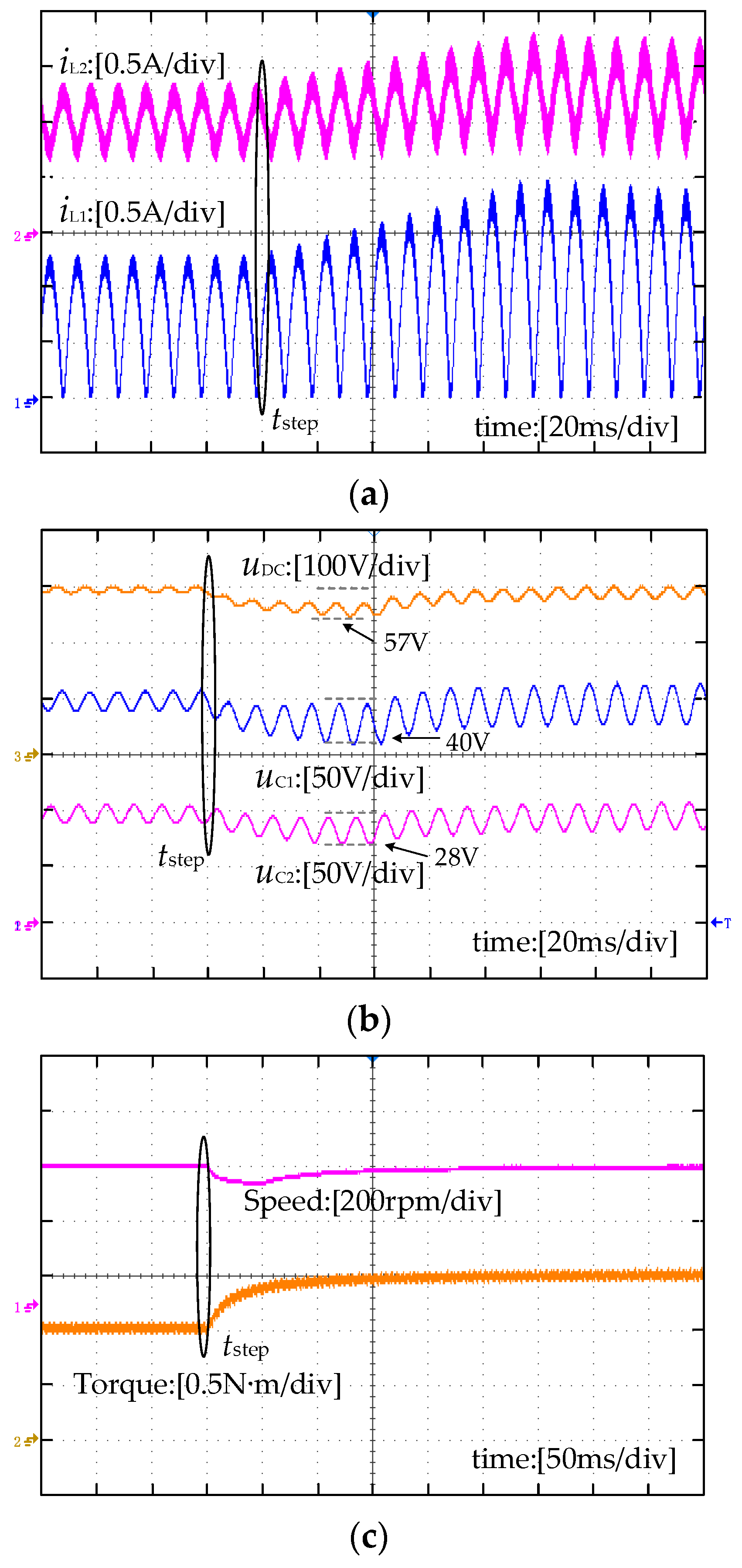
Figure 11 shows the experimental waveforms of the ECL drive system under the traditional PI control strategy. The waveforms in
Figure 11a show that the grid current obviously lags the load change. The waveforms in
Figure 11b show that the maximum drop voltages of C
1 and C
2 are 40 V and 28 V, respectively. As a result, there is a maximum voltage drop of 57 V on the DC-link and there is a speed drop of 67 rpm.
Figure 11c shows the experimental waveforms of the ECL motor drive system with the traditional PI control. It can be seen that the conventional control method takes 160 ms to restore the drop voltage of the DC-link to the set value and takes 100 ms to return the given 500 rpm, which is significantly longer than that of the proposed MPCC.
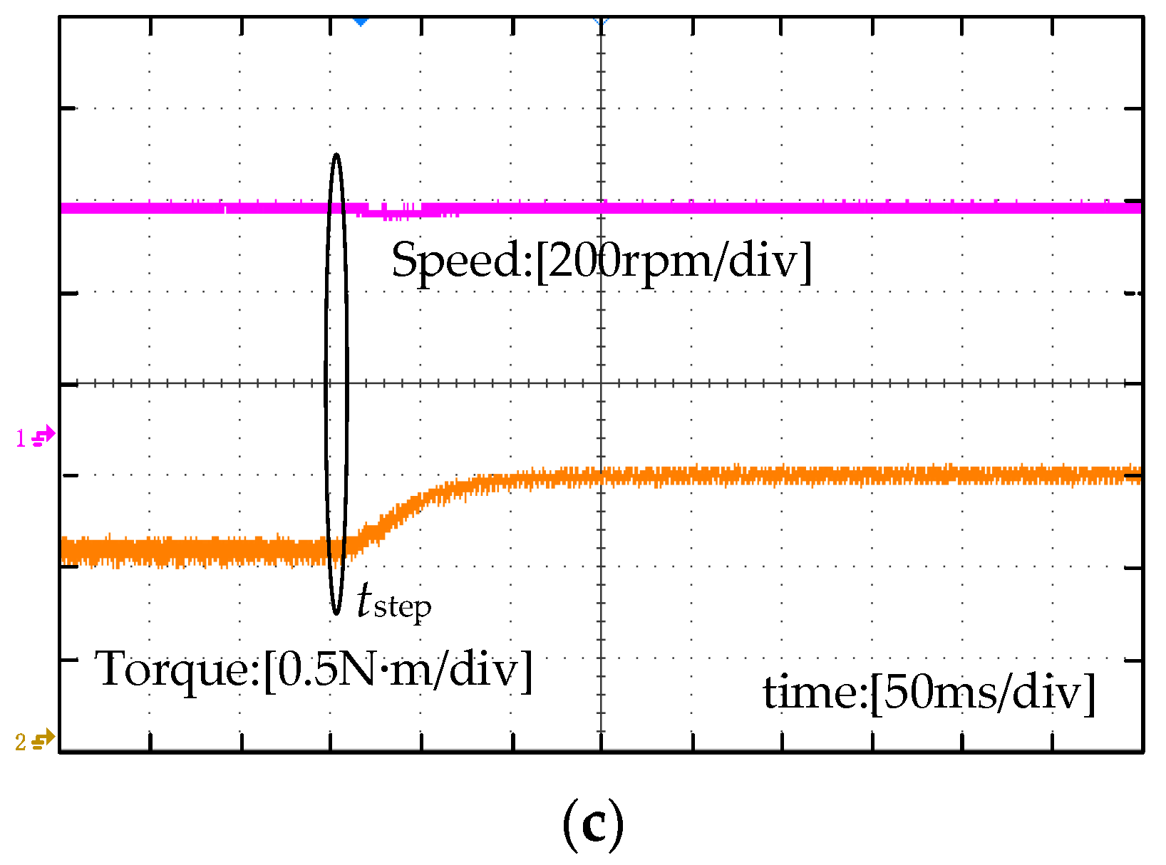
Figure 12 shows the experimental waveforms of the traditional motor driver with bulky electrolytic capacitors. For this motor drive system, there is a maximum drop voltage of 5 V on the DC-link, which does not disturb the PMSM performance. In addition, there is a speed drop of 15 rpm and a speed recovery time of 60 ms.
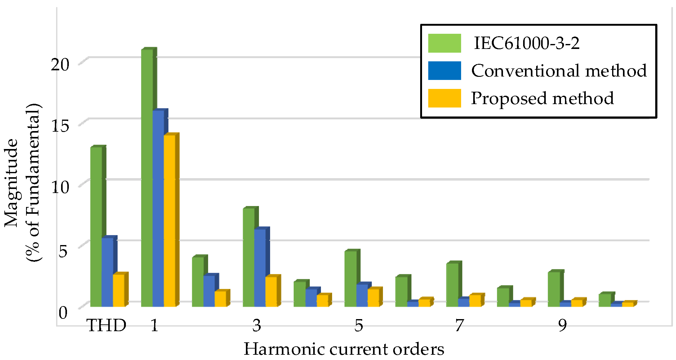
Figure 13 shows that the THD of the grid current based on the proposed MPCC and PI controller both meet the requirement of the standard of IEC61000-3-2. However, the proposed MPCC has a smaller DC-link voltage drop and a better motor dynamic performance, which meets or exceeds that of conventional drive systems with bulky capacitors. Compared with the existing control strategy of ECL drive system, the proposed MPCC has a 50% improvement in response time, a 60% improvement in DC-link voltage recovery time, and a 70% reduction in maximum DC-link voltage drop under variable speed and variable load, which is significantly better than the existing PI control strategies applied in ECL drive systems.


