Article

Cascade-Free Modulated Predictive Direct Speed Control of PMSM Drives

School of Electrical Engineering, China University of Mining and Technology, Xuzhou 221116, China
*
Author to whom correspondence should be addressed.
Energies 2022, 15(19), 7200; https://doi.org/10.3390/en15197200
Submission received: 6 September 2022 / Revised: 23 September 2022 / Accepted: 27 September 2022 / Published: 30 September 2022

Abstract

:
Conventional predictive control for permanent magnet synchronous motors (PMSMs) contains dual speed and current loops, and has a complex structure and multiple parameters to be tuned. Conventional predictive direct speed control (PDSC) exhibits an unsatisfactory steady-state performance. To tackle these issues, this paper presents a cascade-free modulated PDSC (MPDSC) scheme for PMSM drives. First, a speed predictive model is built, where a second-order sliding mode observer is employed to quickly and robustly estimate the load torque. Then, a dual objective cost function with speed and stator current tracking is designed, which improves the system’s steady-state performance. Furthermore, the analytical solution of the constrained optimal voltage vector is derived and it is synthesized by space vector modulation, resulting in a fixed switching frequency. Experimental results show that the proposed MPDSC has stronger robustness, and lower torque ripples and stator current harmonics compared to conventional PDSC.

1. Introduction

A permanent magnet synchronous motor (PMSM) has the merits of a wide operating range, compact structure, high power density, and high efficiency. Hence, it has been extensively applied in new energy power generation systems, electric vehicles, rail transit, power systems, aerospace, etc. [1,2]. It is well known that a PMSM drive system is a complex nonlinear system due to its cross-coupling effects among multiple state variables, which would greatly increase the control complexity. In addition, due to a PMSM’s tough operating conditions in practical applications, system parameters such as stator inductance or external loads may constantly change, which will degenerate the control performance [3]. Therefore, exploring a new control strategy that can realize a simple control structure, satisfactory steady-state accuracy, low total harmonic distortion (THD), and a fast dynamic response, as well as strong robustness to model mismatches for PMSM drives, is still a challenging issue.
Till now, the commonly-used control strategies for PMSM drives in industrial sectors are still the traditional linear control schemes, such as proportional–integral (PI) control. Although a PI control scheme has been widely accepted practically, it usually contains a cascade control structure, multiple parameters to be tuned and hard-to-handle constraints, which cannot meet the high-precision control requirements [4,5]. Nonlinear control schemes such as sliding mode control and model predictive control are considered effective solutions to deal with state-coupling issues [6,7,8]. Among them, model predictive control (MPC), has gained increasing attention in PMSM drives due to its simple concept, and easy to handle multiple control objectives and constraints [9]. The fundamental principles of MPC are described as follows: predicting the future states using a system discrete model, obtaining the optimal control voltage vector by minimizing the performance-dependent cost function, and, finally, applying the resulting optimal vector to the system [10]. Existing MPC schemes for PMSM drives can be classified into three groups: single-vector MPC, double-vector MPC, and multi-vector MPC [11,12,13,14,15,16,17,18]. Each of the MPC schemes has its advantages and disadvantages. Single-vector MPC only performs a single voltage vector during a control period, which can take advantage of the discrete nature of the inverter [11]. However, it results in poor steady-state performance with variable switching frequency, spread harmonic spectrum, and large steady-state torque ripples [12]. Although its performance can be improved by increasing the sampling frequency, the hardware cost is significantly increased [13]. Different from single-vector MPC, two-vector MPC applies two voltage vectors instead of only one to the inverters during a sampling interval. As a result, its steady-state control accuracy is somewhat improved and a quasi-fixed switching frequency is achieved [14,15]. To further enhance the control performance, multi-vector MPC schemes have recently been proposed. Since three voltage vectors are applied to the inverters in a sampling period, the optimal voltage vector (OVV) reference can be synthesized more accurately and the steady-state performance is highly improved. Additionally, a fixed switching frequency would be produced using multi-vector MPC schemes, which reduces the losses and noises compared to single-vector and two-vector MPC schemes [16,17,18].
Nevertheless, conventional MPC schemes for PMSM drives are still built based on a cascaded structure such as the aforementioned cascade PI control, e.g., an outer speed control loop and an inner current control loop. To be specific, they retain the outer-loop speed PI controller while replacing the inner-loop current PI controller with an MPC controller [14,15,16]. Hence, these MPC schemes are essentially predictive current control schemes deployed in cascaded loops, leading to an unsatisfying system dynamic response and increased control complexity. Although a full predictive cascaded speed and current controller is proposed in [19], it still inherits the aforementioned disadvantages of a cascaded structure. To simplify the cascaded structure of conventional predictive current control, several works have investigated the cascade-free predictive direct speed control (PDSC) for PMSM drives [20,21,22,23,24]. The advantages of PDSC schemes are that they only employ a single MPC loop for speed control, thus reducing the implementation complexity. In [20], a finite control-set predictive direct speed control (FCS-PDSC) for PMSM drives is proposed, which somewhat enhances the system dynamic response. Similarly, in [21], an FCS-PDSC scheme is extended for matrix converter-fed PMSM drives. In [22], a delay compensation-considered FCS-PDSC is further proposed to improve the steady-state performance. Nevertheless, the references above are all designed based on single-vector frameworks with a short prediction horizon, which may result in large speed and current ripples. To attenuate these problems, in [23], a PI-like q-axis current reference-based FCS-PDSC scheme is proposed, which is derived based on conventional PI speed control and improves the speed-tracking accuracy to some degree. Nevertheless, this approach still belongs to a single-vector MPC method, which inherits the disadvantages of unfixed switching frequency, high current harmonics, and large torque ripples. To solve these problems, an improved double-vector PDSC is proposed in [24]. However, since only two voltage vectors are employed instead of three, this approach still cannot achieve an optimal control performance as with multi-vector MPC schemes.
To this end, this paper proposes a cascade-free modulated predictive direct speed control (MPDSC) scheme for PMSM drives to further enhance the steady-state performance on the basis of a simple control structure. It is essentially a multi-vector MPC method. The contributions are listed below:
(1)
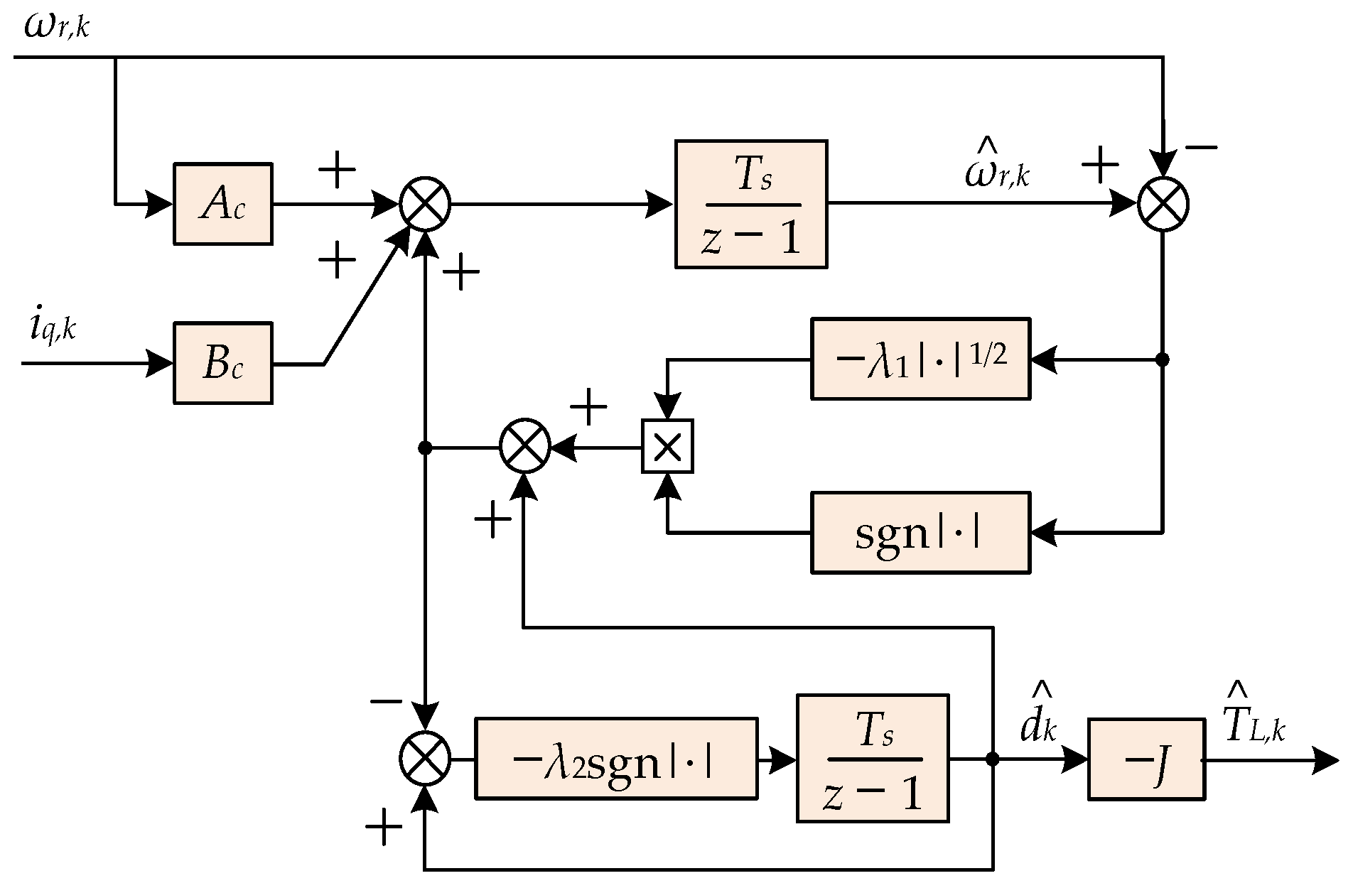
To complete the speed prediction, a second-order sliding mode observer (S2MO) is constructed, which can quickly and robustly estimate the load torque compared to existing observers.
(2)
A dual objective cost function with both speed and current tracking is designed, which reduces the stator current harmonics and torque ripples.
(3)
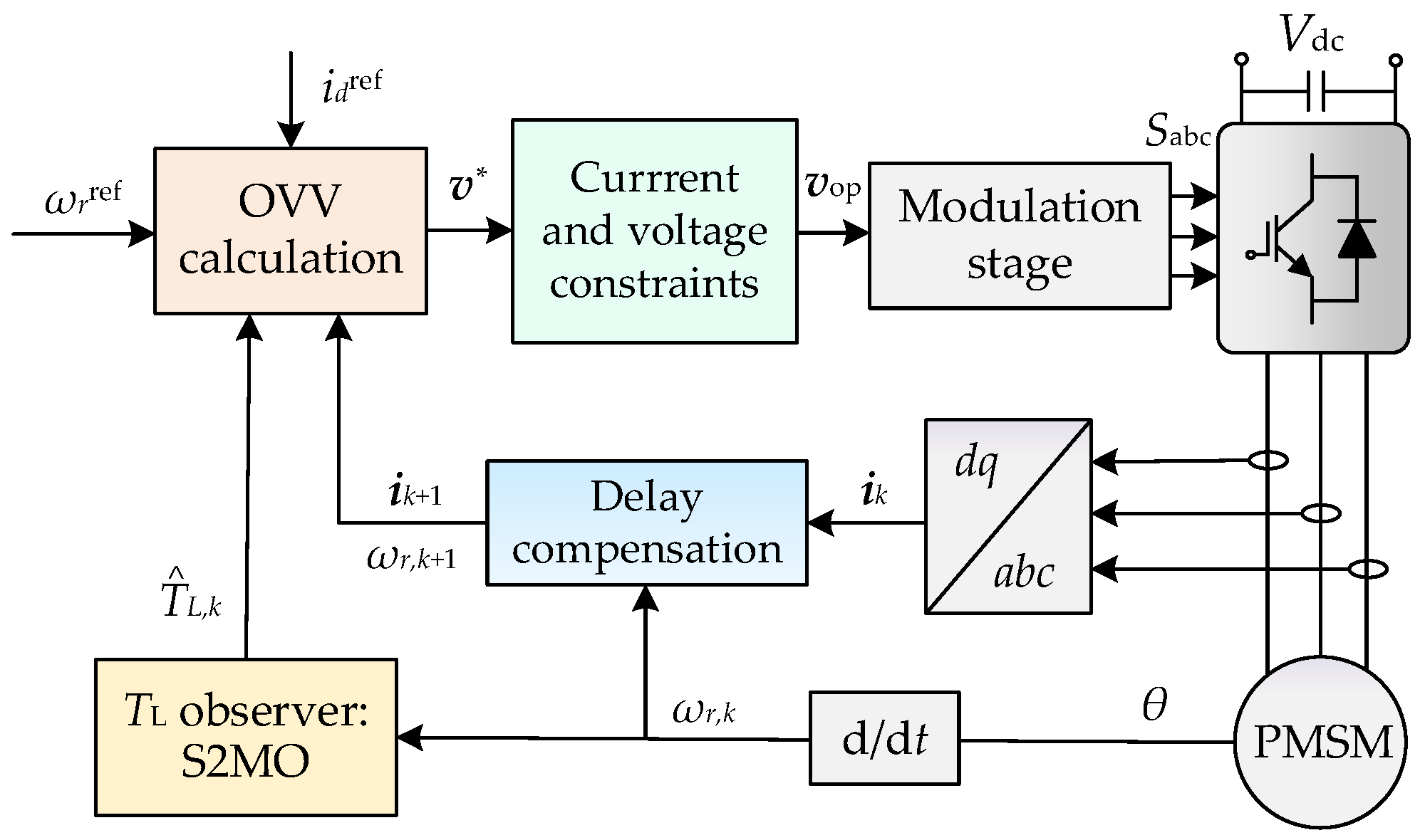
An analytical solution of the OVV with constraints is derived and synthesized by space vector modulation, resulting in a fixed switching frequency and further improving the steady-state performance.
The organization of the paper is as follows. Section 2 provides the mathematical model of a PMSM drive system. In Section 3, the principle of the proposed modulated predictive direct speed control is elaborated. In Section 4, the experimental results and analysis are given. Finally, the conclusions are drawn in Section 5.

2. Modeling of a PMSM Drive System

2.1. System Modeling

The continuous time dynamic model of a PMSM in the dq reference frame is expressed as follows
{ v d = R s i d + L s d d t i d ω e L s i q v q = R s i q + L s d d t i q + ω e ( L s i d + ψ f )
{ J d ω r d t = T e T L B m ω r T e = 1.5 n p ψ f i q
where vd and vq are the d-axis and q-axis inverter voltage, respectively. id and iq are the d-axis and q-axis stator current, respectively. Rs and Ls represent the stator resistance and stator inductance, respectively. ωe and ωr are the electrical and mechanical angular velocities of PMSM, respectively. ψf stands for the flux of rotor permanent magnets. J stands for the rotor inertia, Te and TL represent the electromagnetic torque and load torque, respectively. Bm is the friction coefficient and np is the number of pole pairs.
Supposing the system sampling time is Ts and using the Euler forward discretization method, the discrete predictive model of the system can be obtained as
{ i d , k + 1 = ( 1 T s R s L s ) i d , k + T s ω e , k i q , k + T s L s v d , k i q , k + 1 = ( 1 T s R s L s ) i q , k T s ω e , k i d , k + T s L s v q , k T s ψ f ω e , k L s
ω r , k + 1 = ( 1 T s B m J ) ω r , k + 1.5 n p ψ f T s J i q , k T s T L , k J ,
where the subscript ‘k’ and ‘k + 1′ represent the measured values at the instant of kTs and predictive values at the instant of (k + 1)Ts, respectively.
To facilitate the presentation and analysis, (3) is rewritten as the discrete state-space model form
i k + 1 = A d i k + B d v k + D d
where the matrixes are
A d = [ 1 T s R s L s T s ω e , k T s ω e , k 1 T s R s L s ] ,   B d = [ T s L s 0 0 T s L s ] ,   D d = [ 0 T s ψ f ω e , k L s ] ,
where ik+1 = [id,k+1, iq,k+1]T, ik = [id,k, iq,k]T and vk = [vd,k, vq,k]T represent the stator current and inverter voltage matrixes, respectively.
Note that the speed control system of PMSM is a second-order system since there are two state variables, namely rotor speed and stator current. Considering the essential differences between the electromagnetic time constant and the mechanical time constant, the q-axis stator current served as the control input in (4) should be predicted from the state equation in (3) instead of using its kTs instant value. Hence, the predictive model of the speed should be rewritten as
ω r , k + 1 = ( 1 T s B m J ) ω r , k + 1.5 n p ψ f T s J i q , k + 1 T s T L , k J .

2.2. Delay Compensation

In practice, due to the inherent characteristics of digital controllers, a one-step control delay occurs when implementing PDSC algorisms. The control delay will cause adverse impacts on the dynamic and steady-state performance of the system, such as increasing the current and torque ripple, and even instability of the entire control system. Generally, to compensate for the control delay, a two-step prediction strategy is adopted, i.e., using the predictive values of (k + 2)Ts instant to correct the original prediction model [25]. Specifically, the prediction model of stator current and rotor speed in (5) and (7) with delay compensation is updated as follows
i k + 2 = A d i k + 1 + B d v k + 1 + D d
ω r , k + 2 = ( 1 T s B m J ) ω r , k + 1 + 1.5 n p ψ f T s J i q , k + 2 T s T L , k + 1 J ,
where the stator current and rotor speed at the time interval (k + 1)Ts are calculated by the prediction model (5) and (7) using the optimal voltage vector vdop,k and vqop,k obtained at the previous sampling instant.

3. Proposed Modulated Predictive Direct Speed Control

3.1. Cost Function Design

The key problem of PDSC is the large differences between mechanical and electrical time constants. Conventional PDSC only considers the speed reference tracking, so long prediction horizons are needed to compensate for the difference between the electromagnetic and mechanical dynamics. If the prediction horizon is not long enough to include both dynamics, high-frequency components will appear in the motor currents and consequently results in large speed ripples [23].
To solve this problem, this paper introduces dq-axis stator current error tracking terms into the conventional cost function to improve the speed-tracking accuracy. Considering the one-step control delay compensation, a dual objective cost function for tracking both speed and current is designed below
g = ( ω r ref ω r , k + 2 ) 2 + λ i ( i d ref i d , k + 2 ) 2 + λ i ( i q ref i q , k + 2 ) 2 ,
where λi is the weighting factor, ω r r e f is the speed reference, and d-axis current reference is set to i d ref = 0. It can be seen that the newly designed cost function contains only one weighting factor, which is convenient for parameter tuning.
Then, the q-axis current reference can be obtained from the speed dynamics model. To be specific, when the system reaches the steady state, the changing rate of the speed in (2) is equal to 0. By ignoring the friction coefficient, the q-axis current reference can be calculated as
T L , k + 1 = 1.5 n p ψ f i q i q ref = T L , k + 1 1.5 n p ψ f ,
Hence, the proposed cost function in (10) can simultaneously ensure the optimal tracking of the PMSM’s speed and stator current.

3.2. Unconstrained OVV Derivation

First, ignoring the system constraints, the primary target of the optimization problem is to determine the OVV that minimizes the cost function (10), i.e.,
v * = [ v d * v q * ] T = arg min g ( v d , k + 1 , v q , k + 1 ) ,
The unconstrained OVV can then be calculated by solving the following equations
{ g ( v d , k + 1 , v q , k + 1 ) v d , k + 1 = 0 g ( v d , k + 1 , v q , k + 1 ) v q , k + 1 = 0 ,
Substituting (10) into (13), the unconstrained OVV can be determined and expressed as follows
{ v d * = ( R s L s / T s ) i d , k + 1 ω e , k + 1 L s i q , k + 1 v q * = ( R s L s / T s ) i q , k + 1 + ω e , k + 1 ( L s i d , k + 1 + ψ f ) + D
D = k 1 ( ω r ref ω r , k + 1 ) + k 2 T L , k + 1 + k 3 i q ref ,
where the coefficients are
{ k 1 = 6 J L s n p ψ f 4 λ i J 2 + 9 ( T s n p ψ f ) 2 k 2 = 6 T s L s n p ψ f 4 λ i J 2 + 9 ( T s n p ψ f ) 2 k 3 = 4 λ i J 2 L s / T s 4 λ i J 2 + 9 ( T s n p ψ f ) 2 .
In addition, the second-order partial derivative of the cost function is
{ 2 g ( v d , k + 1 , v q , k + 1 ) v d , k + 1 2 = 2 λ i T s 2 / L s 2 2 g ( v d , k + 1 , v q , k + 1 ) v q , k + 1 2 = 2 λ i T s 2 / L s 2 + 9 T s 4 n p 2 ψ f 2 / ( 2 J 2 L s 2 ) .
It is obvious that (17) is positive, which means that the unconstrained OVV given in (14) can minimize the cost function (10).

3.3. Current Constraint Handling

In practice, the current magnitude should be limited to a safe range to protect the PMSM drive system. Assuming that the maximum allowable current is Imax and considering the delay compensation, the current constraint is expressed as
I k + 2 = i d , k + 2 2 + i q , k + 2 2 I max .
Then, substituting the unconstrained OVV (14) into (8) to calculate the predicted current at (k + 2)Ts instant. If the magnitude of the stator current is within the predefined range (18), the unconstrained OVV is maintained. Otherwise, the stator current should be limited to its maximum value, i.e.,
i max = i k + 2 I k + 2 I max .
As a result, the OVV should be modified according to the maximum current imax. To sum up, the OVV considering the current constraint should be corrected as
v lim = { v * , I k + 2 I max B d 1 ( i max A d i k + 1 D d ) , I k + 2 > I max .

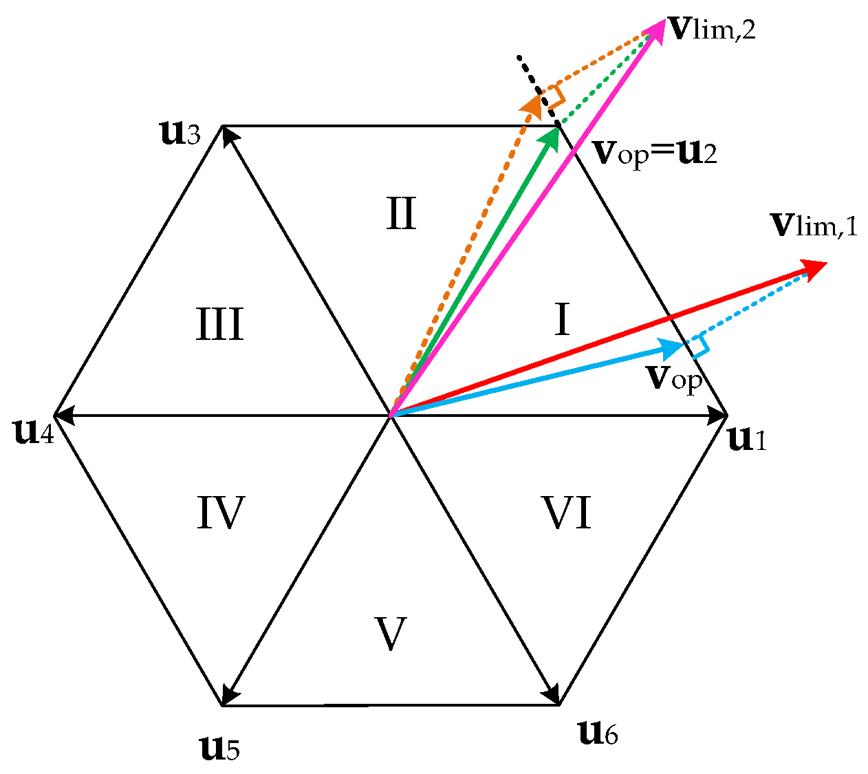
3.4. Voltage Constraint Handling

In addition to the current constraint, the inverter voltage constraint should also be considered. To facilitate the analysis, the current constraint OVV vlim is first transformed to the αβ coordinate through the inverse Park transformation below
[ v lim α v lim β ] = [ cos θ e sin θ e sin θ e cos θ e ] v lim ,
where θe is the rotor electrical angle.
If the current constraint OVV is located in a regular hexagon corresponding to the output voltage limit of the inverter, it remains unchanged. Otherwise, it should be limited to the boundary of the regular hexagon, as shown in Figure 1.
It is known from the geometric relationship that the maximum voltage vector under voltage constraint can be obtained by projecting the current constraint OVV on the boundary, which can minimize the error between constrained and unconstrained OVV. The voltage constraint is illustrated in detail by taking sector I as an example below. In Sector I, the projected current constraint OVV can be expressed as
{ v op α = v lim α 3 v lim β + 2 V dc 4 v op β = 3 ( v op α 2 3 V dc ) ,
where Vdc is the dc link voltage.
Note that the voltage constraint OVV obtained by (22) may exceed the range of sector I. In this case, it should be replaced by the nearest active voltage vector, namely u1 or u2. Finally, the OVV considering both current and voltage constraints is output via space vector modulation (SVM) to achieve a fixed switching frequency.

3.5. Load Torque Observation

It can be seen from (9) that the load torque information is required when implementing the MPDSC scheme. Therefore, a load torque observer usually needs to be designed. The traditional load observers are mostly based on the linear Luenberger observer theory, such as full-order load observers or reduced-order load observers [26]. However, due to the harsh operating conditions of PMSMs, various disturbances and model mismatches will inevitably occur, which leads to large observation errors in traditional load observers. In addition, traditional linear load observers feature a property of asymptotic convergence; that is, the load disturbance estimation is converged in infinite time, which may affect the system dynamic response.
Note that the second-order sliding mode observer not only has strong robustness to various disturbances but also converges in finite time. Moreover, the chattering is significantly attenuated compared to conventional sliding mode observers [27]. Therefore, the second-order sliding mode observer, which combines the above advantages, is more suitable for stable, accurate, and robust observation of load torque.
First, the simplest form of an S2MO is expressed as
{ x ^ ˙ ( t ) = u ( t ) + v ( t ) v ( t ) = λ 1 | x ^ ( t ) x ( t ) | 1 / 2 sgn [ x ^ ( t ) x ( t ) ] + z ^ ( t ) z ^ ˙ ( t ) = λ 2 sgn [ z ^ ( t ) v ( t ) ] ,
where x(t) and z(t) represent system state variables and disturbances, respectively. x ^ ( t ) and z ^ ( t ) represent the estimated values of system state variables and disturbances, respectively. λ1 and λ2 are positive gains of the observer. Notation ‘sgn’ is a sign function.
Then, using the Euler forward discretization method, (23) can be discretized as
{ x ^ k + 1 = x ^ k + T s ( u k + v k ) v k = λ 1 | x ^ k x k | 1 / 2 sgn ( x ^ k x k ) + z ^ k z ^ k + 1 = z ^ ˙ k T s λ 2 sgn ( z ^ k v k ) .
Regarding the analysis of discretization modeling error, more details are investigated in [28,29], which are not detailed here. Applying (24) to the discrete speed dynamics model in (4), the second-order sliding mode load torque observer is designed as
{ ω ^ r , k + 1 = ω ^ r , k + T s [ λ 1 | ω ^ r , k ω r , k | 1 / 2 sgn ( ω ^ r , k ω r , k )             + A c ω r , k + B c i q , k + d ^ k ] d ^ k + 1 = d ^ k T s λ 2 sgn [ λ 1 | ω ^ r , k ω r , k | 1 / 2 sgn ( ω ^ r , k ω r , k ) ] ,
where the matrices
A c = B m J , B c = 1.5 n p ψ f J , d k = T L , k J .
As a result, the observed disturbance d ^ k is further converted into the load torque as
T ^ L , k = J d ^ k .
Figure 2 shows the block diagram of the designed second-order sliding mode load torque observer for a PMSM.
Finally, the overall block diagram for implementation of the proposed cascade-free MPDSC scheme for PMSM drives is shown in Figure 3.

3.6. Experimental Setup

To verify the effectiveness of the proposed MPDSC, experiments are carried out in this section. Figure 4 shows the experimental platform, which consists of a DC source, a surface-mounted PMSM, a hysteresis-brake load, a two-level three-phase voltage-source inverter, an LEM box for current sampling, and a host PC. Moreover, a TMS320F28335-DSP is used for algorithm implementation. The parameters of the PMSM drive system are listed in Table 1. Moreover, the state-of-the-art double-vector PDSC proposed in [24] is implemented for performance comparison. The sampling frequency fs and switching frequency fsw for both control methods are set as 10 kHz. The weighting factor λi is set as 1 to achieve good balance between the speed and stator current control objectives.

4. Experimental Results and Analysis

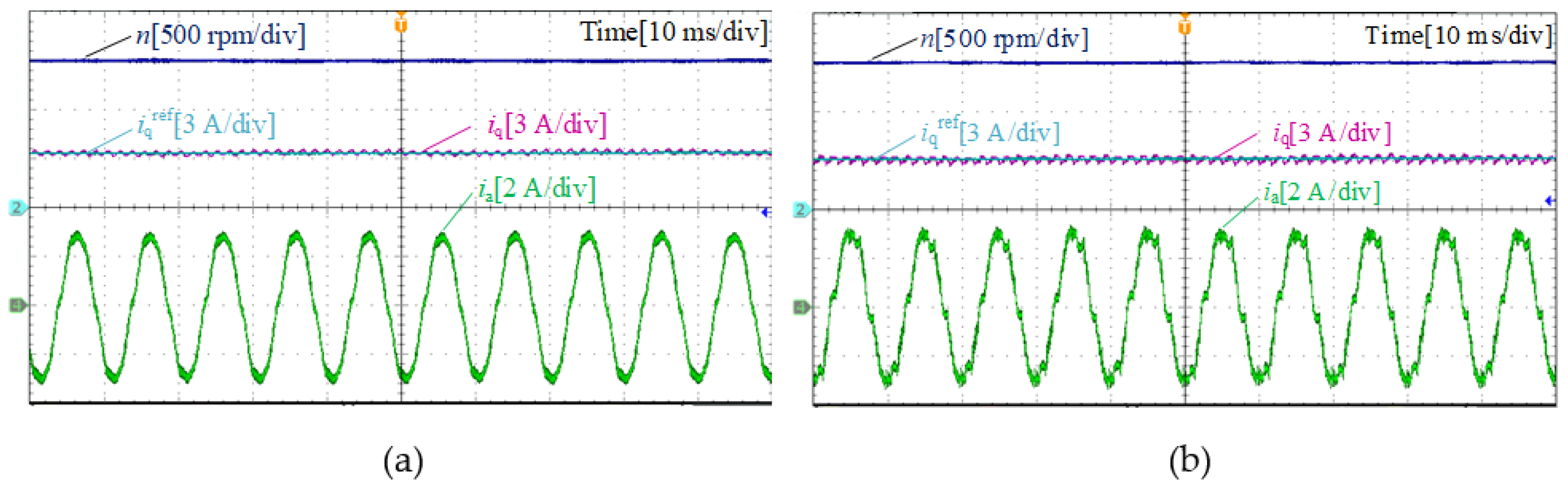
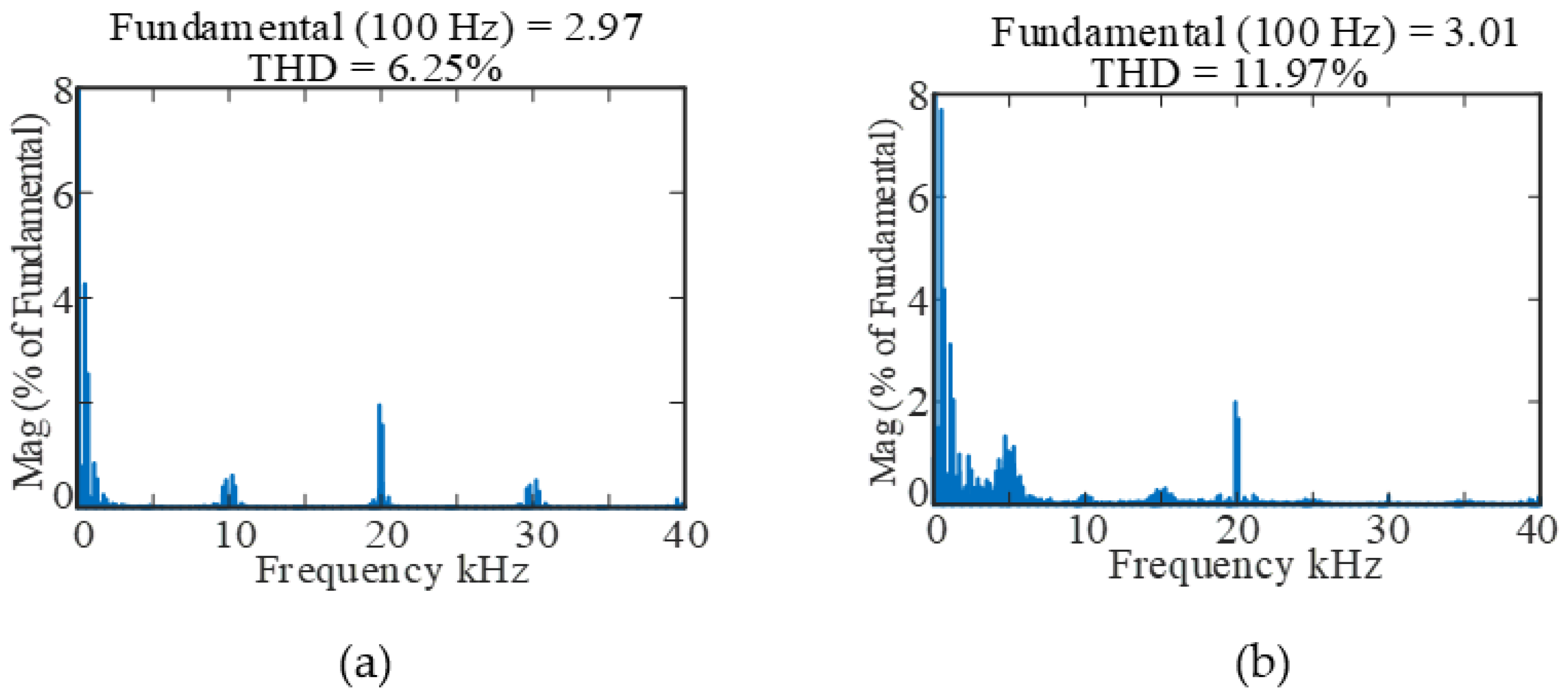
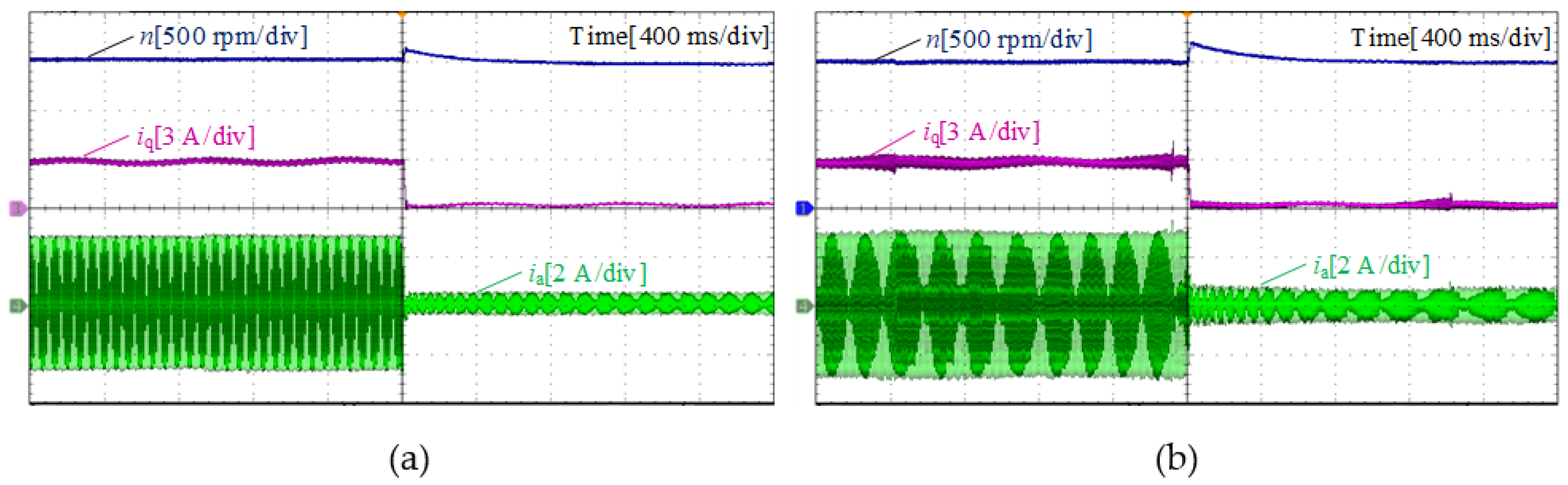
4.1. Steady-State Performance

Figure 5 shows the steady-state experimental waveforms of the proposed MPDSC and double-vector PDSC at the speed of 1500 rpm, and Figure 6 shows the corresponding stator current harmonic spectrum. It can be seen from Figure 5 that both methods can track the speed and current reference well. However, since the proposed MPDSC features a fixed switching frequency and applies three voltage vectors in one sampling period, the current ripple is reduced compared with the double-vector PDSC. It can be seen from Figure 6 that the stator current THD using the proposed method is reduced by about 50% (from 11.97% to 6.25%) compared with using the double-vector PDSC, which reveals that the proposed method can achieve better steady-state performance.

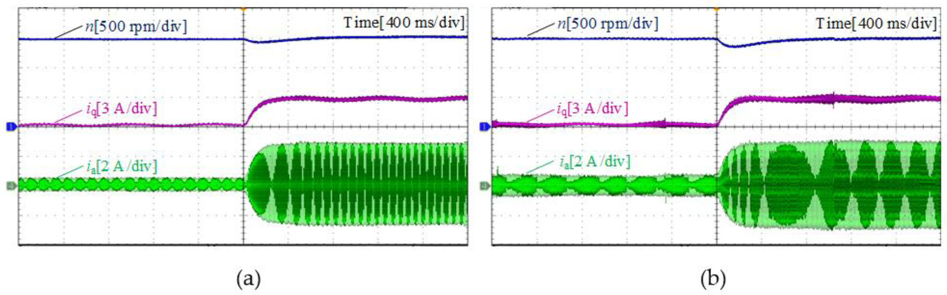
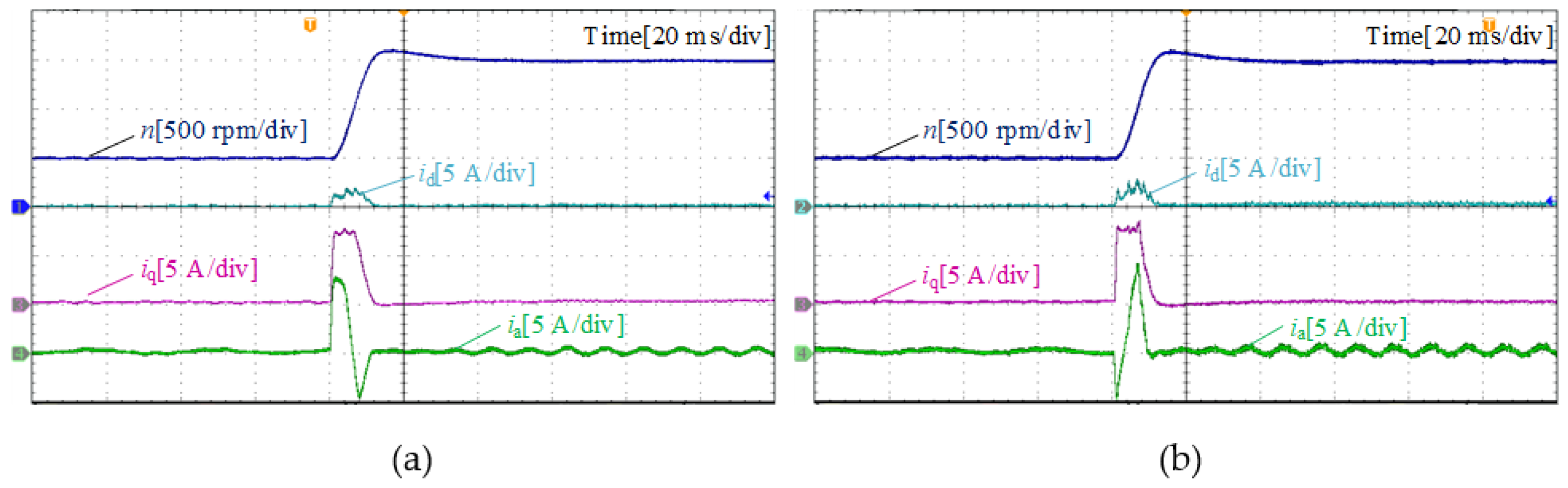
4.2. Dynamic Performance

4.2.1. Load Torque Variations

Figure 7 and Figure 8 depict the dynamic response of two methods under a sudden load torque change, where the speed reference is 1500 rpm. It can be seen that the speed drop and settling time of the proposed method are much lower than those of the double-vector PDSC when the load torque increases from 0 Nm to 0.2 Nm. Similar experimental results are also obtained when unloading. It can be seen that the speed fluctuation using double-vector PDSC is 30 rpm, while that with the proposed method is 15 rpm. Hence, the proposed MPDSC method has a faster dynamic response and is more robust to load disturbances compared with the double-vector PDSC.

4.2.2. Speed-Regulation Performance

In Figure 9, the experimental results of speed-regulation performance under the no-load conditions are compared, where the reference speed changes from 500 rpm to 1500 rpm. As shown in Figure 9, similar dynamic performance appears in two methods.

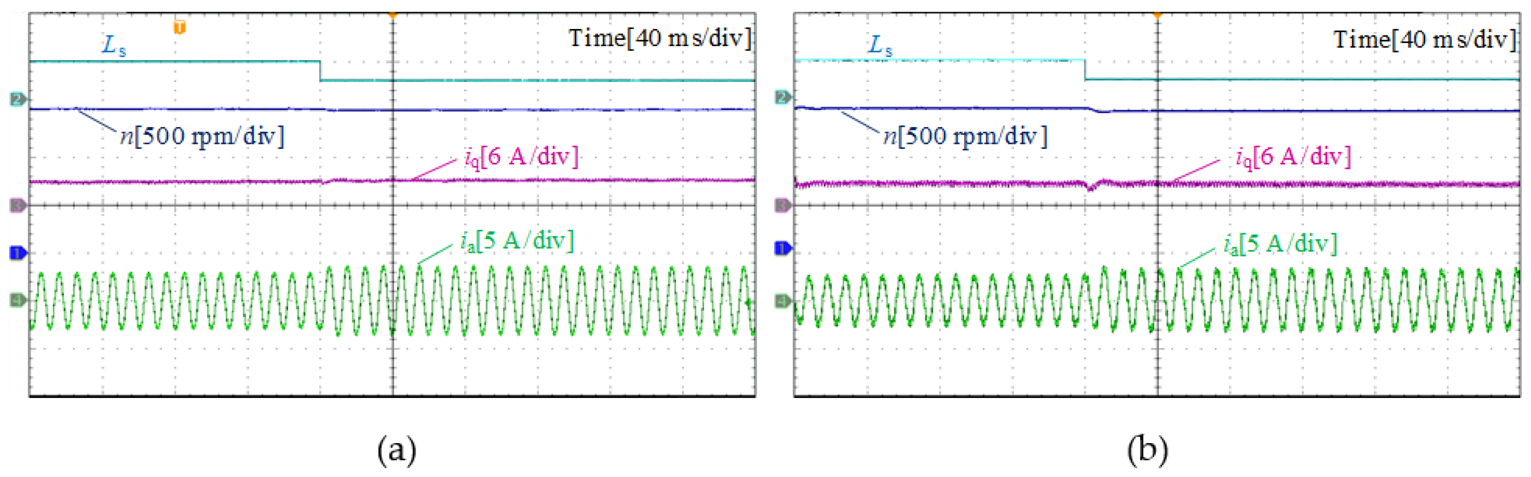
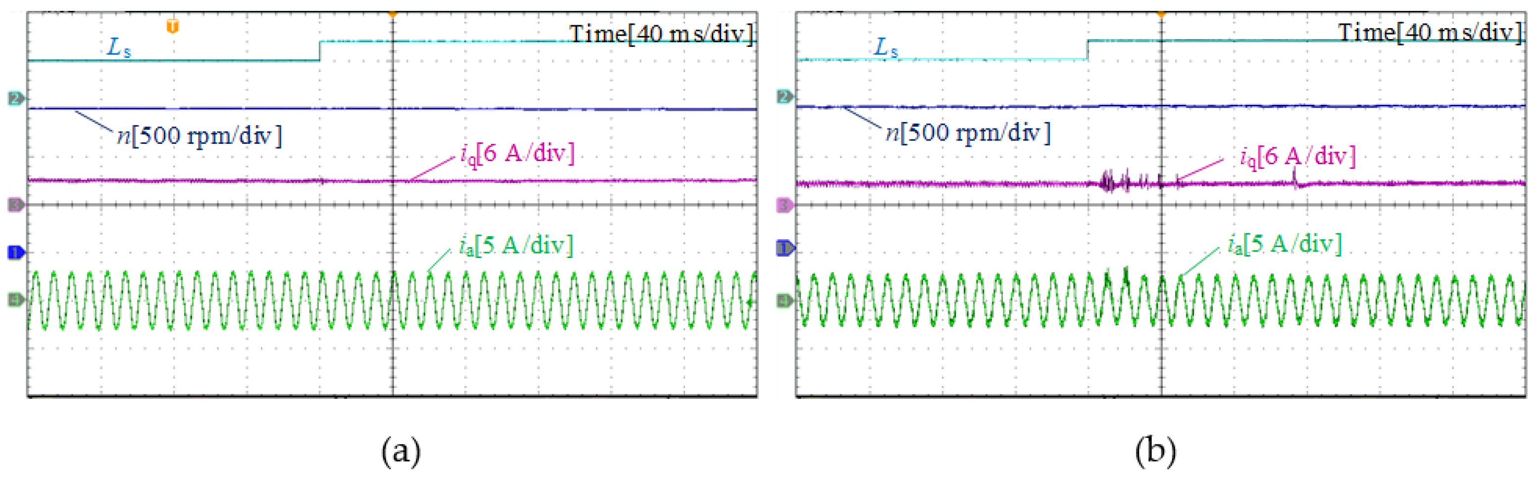
4.3. Robustness Evaluation

To investigate the sensitivity to model mismatches using the proposed MPDSC, experimental comparisons under different stator inductance mismatches are carried out. Figure 10 shows the experimental comparisons with a −50% Ls mismatch in the controller, while Figure 11 shows the experimental comparisons with a +50% Ls mismatch in the controller. It can be observed that PMSM can operate stably with both methods under a certain model mismatch. However, when the double-vector PDSC is adopted, the speed of PMSM decreases and cannot be restored with a −50% Ls mismatch. When there exists a +50% Ls mismatch, slight oscillations appear in stator current with double-vector PDSC. Therefore, the proposed method is proved to have stronger robustness to stator inductance mismatches compared to double-vector PDSC.

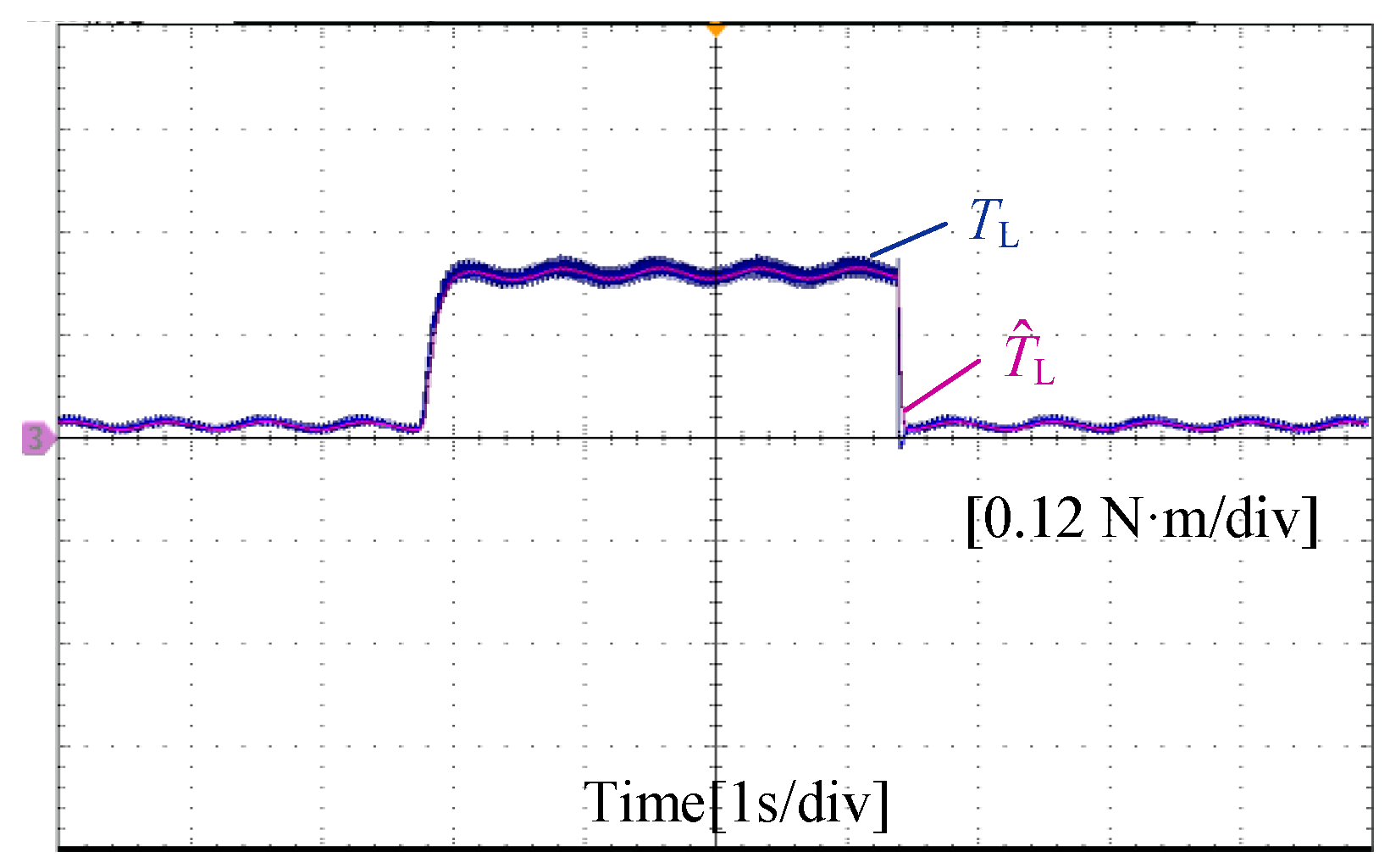
4.4. Load Torque Observation Evaluation

Figure 12 shows the experimental results of the designed second-order sliding mode load torque observer, where the blue line represents the actual load torque and the mauve line represents the observed load torque. It can be seen from Figure 12 that the S2MO can quickly and smoothly track the load torque in the transient process. Moreover, since the S2MO introduces an integral action, the chattering effect is greatly weakened.

4.5. Discussion

Existing predictive direct speed control for PMSM drives has been able to simplify the control structure and parameter tuning work, which is simple in implementation. However, the main idea of this paper is to further improve the steady-state performance and robustness to load variations compared to state-of-the-art predictive direct speed control. Experimental results reveal that the steady-state torque ripples and stator current THD are reduced. Nevertheless, the weighting factor design is based on trial-and-error in this paper, and the theoretical guidelines for weighting factor selection are required to achieve an optimal control performance, which will be our future work.

5. Conclusions

This paper proposes a cascade-free modulated predictive speed control scheme of PMSM drives for steady-state performance and robustness enhancement. To realize the speed predictions, a second-order sliding mode observer is firstly employed for fast and robust load torque estimation. Then, a dual objective cost function with both speed and current tracking is firstly constructed, enhancing the steady-state tracking accuracy. Finally, to achieve a fixed switching frequency, the analytical solution of the constrained optimal voltage vector with constraints is derived offline, which is finally synthesized by space vector modulation. Experimental results are provided, which verify that the proposed MPDSC can achieve improved steady-state performance (reducing 50% of stator current THD), and stronger robustness to load variations (reducing 50% of speed fluctuations) compared with conventional double-vector PDSC.

Author Contributions

Conceptualization, C.Z.; methodology, C.Z. and J.Y.; software, Z.X. and X.D.; validation, C.Z., J.Y., Z.G., Z.X. and X.D.; formal analysis, C.Z. and J.Y.; investigation, C.Z., J.Y., Z.G., Z.X. and X.D.; resources, C.Z.; data curation, C.Z., J.Y., Z.G., Z.X. and X.D.; writing—original draft preparation, C.Z. and J.Y.; writing—review and editing, C.Z., J.Y. and Z.G.; visualization, C.Z., J.Y., Z.G., Z.X. and X.D.; supervision, C.Z. and Z.G.; project administration, C.Z. and Z.G.; funding acquisition, C.Z. and Z.G. All authors have read and agreed to the published version of the manuscript.

Funding

This work was supported in part by the Natural Science Foundation of Jiangsu Province under Grant BK20190630, in part by the National Natural Science Foundation of China under Grant 51907196, 52107217 and 52277205.

Data Availability Statement

Not applicable.

Conflicts of Interest

The authors declare no conflict of interest.

References

  1. Siami, M.; Khaburi, D.A.; Abbaszadeh, A.; Rodriguez, J. Robustness improvement of predictive current control using prediction error correction for permanent-magnet synchronous machines. IEEE Trans. Ind. Electron. 2016, 63, 3458–3466. [Google Scholar] [CrossRef]
  2. Zhang, Y.; Deng, F.; Hou, J.; Jiang, P.; Zhang, H.; Zhu, K.; Hu, Y.; Vazquez, S. Cascaded modular multilevel converter and cycloconverter based machine drive system. IEEE Trans. Ind. Electron. 2022. [Google Scholar] [CrossRef]
  3. Yang, M.; Lang, X.; Long, J.; Xu, D. Flux immunity robust predictive current control with incremental model and extended state observer for PMSM drive. IEEE Trans. Power Electron. 2017, 32, 9267–9279. [Google Scholar] [CrossRef]
  4. Belkhier, Y.; Achour, A.; Ullah, N.; Shaw, R.N.; Farooq, Z.; Ullah, A.; Alzaed, A.N. Intelligent energy-based modified super twisting algorithm and factional order PID control for performance improvement of PMSG dedicated to tidal power system. IEEE Access 2021, 9, 57414–57425. [Google Scholar] [CrossRef]
  5. Wang, Q.; Ding, Z.; Cheng, M.; Deng, F.; Buja, G. Direct power control of three-phase electric springs. IEEE Trans. Ind. Electron. 2021, 69, 13033–13044. [Google Scholar] [CrossRef]
  6. Gong, Z.; Li, J.; Dai, P.; Su, D.; Wu, X. Design and evaluation of a virtual vector based modulated model predictive control for the indirect matrix converters with improved performance. IEEE Trans. Ind. Electron. 2021, 69, 12019–12029. [Google Scholar] [CrossRef]
  7. Zheng, C.; Dragicevic, T.; Blaabjerg, F. Current-sensorless finite-set model predictive control for LC-filtered voltage source inverters. IEEE Trans. Power Electron. 2020, 35, 1086–1095. [Google Scholar] [CrossRef]
  8. Belkhier, Y.; Shaw, R.N.; Bures, M.; Islam, M.R.; Bajaj, M.; Albalawi, F.; Alqurashi, A.; Ghoneim, S.S.M. Robust interconnection and damping assignment energy-based control for a permanent magnet synchronous motor using high order sliding mode approach and nonlinear observer. Energy Rep. 2022, 8, 1731–1740. [Google Scholar] [CrossRef]
  9. Vazquez, S.; Rodriguez, J.; Rivera, M.; Franquelo, L.G.; Norambuena, M. Model predictive control for power converters and drives: Advances and trends. IEEE Trans. Ind. Electron. 2017, 64, 935–947. [Google Scholar] [CrossRef]
  10. Karamanakos, P.; Geyer, T. Guidelines for the design of finite control set model predictive controllers. IEEE Trans. Power Electron. 2020, 35, 7434–7450. [Google Scholar] [CrossRef]
  11. Xie, W.; Wang, X.; Wang, F.; Xu, W.; Kennel, R.M.; Gerling, D.; Lorenz, R.D. Finite-control-set model predictive torque control with a deadbeat solution for PMSM drives. IEEE Trans. Ind. Electron. 2015, 62, 5402–5410. [Google Scholar] [CrossRef]
  12. Xu, S.; Sun, Z.; Yao, C.; Zhang, H.; Hua, W.; Ma, G. Model predictive control with constant switching frequency for three-level t-type inverter-fed PMSM drives. IEEE Trans. Ind. Electron. 2022, 69, 8839–8850. [Google Scholar] [CrossRef]
  13. Zheng, C.; Dragicevic, T.; Blaabjerg, F. Model predictive control-based virtual inertia emulator for an islanded alternating current microgrid. IEEE Trans. Ind. Electron. 2021, 68, 7167–7177. [Google Scholar] [CrossRef]
  14. Zhang, X.; Hou, B. Double Vectors Model predictive torque control without weighting factor based on voltage tracking error. IEEE Trans. Power Electron. 2018, 33, 2368–2380. [Google Scholar] [CrossRef]
  15. Chen, W.; Zeng, S.; Zhang, G.; Shi, T.; Xia, C. A modified double vectors model predictive torque control of permanent magnet synchronous motor. IEEE Trans. Power Electron. 2019, 34, 11419–11428. [Google Scholar] [CrossRef]
  16. Li, X.; Xue, Z.; Yan, X.; Zhang, L.; Ma, W.; Hua, W. Low-complexity multivector-based model predictive torque control for PMSM with voltage preselection. IEEE Trans. Power Electron. 2021, 36, 11726–11738. [Google Scholar] [CrossRef]
  17. Zheng, C.; Dragicevic, T.; Zhang, Z.; Rodriguez, J.; Blaabjerg, F. Model predictive control of LC-filtered voltage source inverters with optimal switching sequence. IEEE Trans. Power Electron. 2021, 36, 3422–3436. [Google Scholar] [CrossRef]
  18. Jiang, X.; Yang, Y.; Fan, M.; Ji, A.; Xiao, Y.; Zhang, X.; Zhang, W.; Garcia, C.; Vazquez, S.; Rodriguez, J. An improved implicit model predictive current control with continuous control set for PMSM drives. IEEE Trans. Transp. Electrif. 2022, 8, 2444–2455. [Google Scholar] [CrossRef]
  19. Garcia, C.; Rodriguez, J.; Silva, C.; Rojas, C.; Zanchetta, P.; Abu-Rub, H. Full predictive cascaded speed and current control of an induction machine. IEEE Trans. Energy Convers. 2016, 31, 1059–1067. [Google Scholar] [CrossRef]
  20. Preindl, M.; Bolognani, S. Model predictive direct speed control with finite control set of PMSM drive systems. IEEE Trans. Power Electron. 2013, 28, 1007–1015. [Google Scholar] [CrossRef]
  21. Formentini, A.; Trentin, A.; Marchesoni, M.; Zanchetta, P.; Wheeler, P. Speed finite control set model predictive control of a PMSM fed by matrix converter. IEEE Trans. Ind. Electron. 2015, 62, 6786–6796. [Google Scholar] [CrossRef]
  22. Han, Y.; Gong, C.; Yan, L.; Wen, H.; Wang, Y.; Shen, K. Multiobjective finite control set model predictive control using novel delay compensation technique for PMSM. IEEE Trans. Power Electron. 2020, 35, 11193–11204. [Google Scholar] [CrossRef]
  23. Kakosimos, P.; Abu-Rub, H. Predictive speed control with short prediction horizon for permanent magnet synchronous motor drives. IEEE Trans. Power Electron. 2018, 33, 2740–2750. [Google Scholar] [CrossRef]
  24. Zhang, X.; He, Y. Direct voltage-selection based model predictive direct speed control for PMSM drives without weighting factor. IEEE Trans. Power Electron. 2019, 34, 7838–7851. [Google Scholar] [CrossRef]
  25. Zheng, C.; Gong, Z.; Wu, X.; Dragicevic, T.; Rodriguez, J.; Blaabjerg, F. Finite-set quasi-sliding mode predictive control of LC-filtered voltage source inverters. IEEE Trans. Ind. Electron. 2022, 69, 11968–11978. [Google Scholar] [CrossRef]
  26. Yan, L.; Song, X. Design and implementation of luenberger model-based predictive torque control of induction machine for robustness improvement. IEEE Trans. Power Electron. 2020, 35, 2257–2262. [Google Scholar] [CrossRef]
  27. Zhao, L.; Huang, J.; Liu, H.; Li, B.; Kong, W. Second-order sliding-mode observer with online parameter identification for sensorless induction motor drives. IEEE Trans. Ind. Electron. 2014, 61, 5280–5289. [Google Scholar] [CrossRef]
  28. Sankaranarayanan, V.N.; Yadav, R.D.; Swayampakula, R.K.; Ganguly, S.; Roy, S. Robustifying payload carrying operations for quadrotors under time-varying state constraints and uncertainty. IEEE Robot. Autom. Lett. 2022, 7, 4885–4892. [Google Scholar] [CrossRef]
  29. Ganguly, S.; Sankaranarayanan, V.N.; Suraj, B.V.S.G.; Dev Yadav, R.; Roy, S. Efficient manoeuvring of quadrotor under constrained space and predefined accuracy. In Proceedings of the IEEE International Conference on Intelligent Robots and Systems, Prague, Czech Republic, 27 September–1 October 2021; pp. 6352–6357. [Google Scholar]
Figure 1. The OVV with voltage constraint.
Energies 15 07200 g001
Figure 2. Block diagram of the second-order sliding mode load torque observer.
Energies 15 07200 g002
Figure 3. Block diagram of the proposed cascade-free MPDSC for PMSM drives.
Energies 15 07200 g003
Figure 4. Experimental platform for verifying the proposed MPDSC.
Energies 15 07200 g004
Figure 5. Steady-state experimental waveforms. (a) Proposed MPDSC. (b) Double-vector PDSC.
Energies 15 07200 g005
Figure 6. Steady-state stator current harmonic spectrum. (a) Proposed MPDSC. (b) Double-vector PDSC.
Energies 15 07200 g006
Figure 7. Dynamic experimental waveforms when the load torque suddenly changes from 0 Nm to 0.2 Nm. (a) Proposed MPDSC. (b) Double-vector PDSC.
Energies 15 07200 g007
Figure 8. Dynamic experimental waveforms when the load torque suddenly changes from 0.2 Nm to 0 Nm. (a) Proposed MPDSC. (b) Double-vector PDSC.
Energies 15 07200 g008
Figure 9. Dynamic experimental waveforms when the reference speed changes from 500 rpm to 1500 rpm. (a) Proposed MPDSC. (b) Double-vector PDSC.
Energies 15 07200 g009
Figure 10. Experimental comparison with a −50% Ls mismatch. (a) Proposed MPDSC. (b) Double-vector PDSC.
Energies 15 07200 g010
Figure 11. Experimental comparison with a +50% Ls mismatch. (a) Proposed MPDSC. (b) Double-vector PDSC.
Energies 15 07200 g011
Figure 12. Evaluation of the second-order sliding mode load torque observer.
Energies 15 07200 g012
Table 1. Parameters of the PMSM drive system.
ParametersSymbolsValues
DC link voltageVdc36 V
Stator inductanceLs0.85 mH
Stator resistanceRs0.375 Ω
Rotor flux linkageψf0.01 Wb
Pole pairsnp4
InertiaJ6 × 10−6 kg·m2
Rated speednN2000 rpm
Rated torqueTN0.3 N·m
Publisher’s Note: MDPI stays neutral with regard to jurisdictional claims in published maps and institutional affiliations.

