Abstract
Induction motors have gained a renewed interest due to this new shift from conventional power sources to electric power. These motors are known for their high commencing torque, adequate speed control and reasonable overload capacity. However, induction motors have an innate thermal issue wherein their lifespan and performance are strongly temperature dependent. Hence, it is highly essential to focus on the thermal management aspect of these motors to ensure reliability and enhance performance. Thus, the major purpose of the paper is to comprehensively review various approaches and methods for thermal analysis, including finite element analysis, lumped parameter thermal network and computational fluid dynamics tools. Moreover, it also presents various cooling strategies commonly adopted in induction motors. Furthermore, this study also suggests an integrated approach with two or more cooling strategies to be the need of the hour. These will combine the benefits of the individual system while helping to counter their drawbacks. This study will help to serve members of the scientific community, manufacturers or motors users who are interested in the thermal management of induction motors.
1. Introduction
Electric motors find their application in a wide range of industries from home appliances to transportation, including automotive and aerospace applications. A special type of motor called the induction motor has gained importance in recent times due to its high commencing torque, adequate speed regulation and reasonable overload capacity [1]. The mechanical power is produced due to the interactions between the magnetic field by the stator winding and the cage bar [2]. Moreover, IMs are a type of non-magnetic motor, thereby proving to be a promising option because of the shortage of rare-earth metals. However, a major drawback of IMs is their inherent thermal problem wherein the lifespan and efficiency are dependent on temperature [3]. The Arrhenius equation states that the lifespan of the entire motor is halved every time the functioning temperature is increased by 10 °C [4].
Thus, to ensure reliability and improve the machine performance, it is needed to emphasize the thermal management of IMs. In the past, motor designers have overlooked thermal analysis and dealt with the heating problem either by experience or varying other sizing variables, such as current density, etc. [5]. These methods lead to applying a large factor of safety, to deal with the worst heating situations, thereby leading to oversizing of the machine and, in turn, increasing the cost [6].
Analytical lumped circuits and numerical methods are the two basic classifications for thermal analysis [7]. The main advantage of the analytical approach is its ability to compute fast and accurately. However, many efforts need to be invested to define the circuit that is accurate enough to model the heat paths. On the other hand, numerical methods can be majorly classified into computational fluid dynamics (CFD) and structural thermal analysis (STA), where both use the finite element analysis (FEA) [8]. The numerical analysis gives us the advantage that the machine prototype geometry model could be made. Nevertheless, in terms of model arrangement and computation time, it could be demanding sometimes [9].
Moreover, various cooling strategies, such as air-cooled, liquid-cooled or heat pipe/plate cooled, can be employed to enhance the cooling characteristics of the machine [10]. In this paper, various thermal analysis approaches are contrasted. Additionally, various cooling strategies are discussed and compared, which refers to approaches for thermal analyses too. Thus, the study aims to broadly review the different aspects of the thermal management of IMs and suggest suitable changes, which will further improve the thermal efficiency of the machine.
2. Types of Losses
The various losses in an IM were described in Bin et al. [11] in Figure 1. However, in this review paper, only the major losses, that is, iron losses, copper losses and mechanical losses have been considered in the following section.
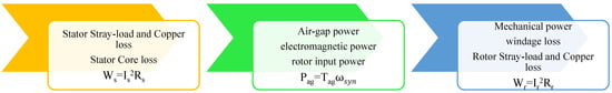
Figure 1.
Power losses inside IM [11].
2.1. Copper Losses
All the IMs predominantly suffer this loss majorly due to Joule heating caused by the resistivity of the conductors. In addition to this, the overall copper losses are highly impacted by the proximity and frequency-dependent skin effects [12]. The copper losses are also temperature-dependent whose effect can be determined by substituting the resistivity as a function of temperature [13].
where, , temperature at the initial state, T, temperature at the final state, , resistivity at and represents the coefficient of temperature.
2.2. Iron Losses
Iron losses are the second most dominant type of loss, which produces hysteresis and eddy current losses in IMs, primarily instigated by time-varying magnetic fields [14]. The core losses are primarily quantified by the Steinmetz equation whose coefficients can be treated as constants or variables depending on the operating conditions [15].
To analyze the iron loss in an inverter-fed induction motor, a piecewise variable parameter iron loss (PVPIL) model could be used [16], where the PVPIL model is useful to determine the effect of diverse extents and frequencies of flux densities on the hysteresis and eddy current losses. According to the PVPIL model, the iron losses can also be described by the expression [16]:
The hysteresis loss according to the PVPIL model is given as:
The eddy current losses due to the model PVPIL is expressed as:
where, v is vth element in the FE-model, and are the maximum values of the nth flux density harmonic’s tangential and normal components in vth element. is the frequency of the nth flux density harmonic in the vth element. krv is the rotating magnetizing coefficient and Av is the vth element’s area in vth element. The variable parameters and are changed with and . Similarly, and are changed with and . Additionally, and are changed with and . Additionally, and are changed with and .
2.3. Mechanical Losses
Windage and friction losses are the two major causes of mechanical loss produced in an IM. Friction losses that are heat-dependent are significantly related to bearings. The friction ultimately leads to heat generations, thereby increasing the local temperature. Minimization of the loss could be done with the help of lubricants and good quality bearings. The mechanical windage and friction loss are given as [17]:
3. Thermal Analysis Approach
Thermal management of an IM requires the accurate prediction of temperature profiles using different thermal analytical approaches. Apart from experimental validation, CFD and LPTN are some of the commonly used analytical approaches. The advantages and disadvantages of different approaches have been highlighted in Figure 2.
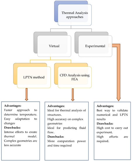
Figure 2.
Comparison of different thermal analysis approaches.
3.1. LPTN-Lumped Parameter Thermal Network
The lumped circuit model is a faster approach to determining the temperature profile within the IM, where the variations consequential from diverse input parameters could be rapidly determined by the user. The steady state or transient heat flow in an IM and the temperature of each component can be predicted using this model. The temperature profile of the system is found to be similar to that of the temperature profile found in the CFD simulation made through FEA, as long as the geometry remains simple. However, the major drawback of the LPTN model is the intense effort required for creating an accurate model [18]. In this model, complex geometry is presented by lumping different components of it into simplified areas [18,19,20]. An example of lumped parameter thermal network of an electrical IM from Nair DG et al. [20] is displayed in Figure 3 where the IM is of 37 kW capacity.
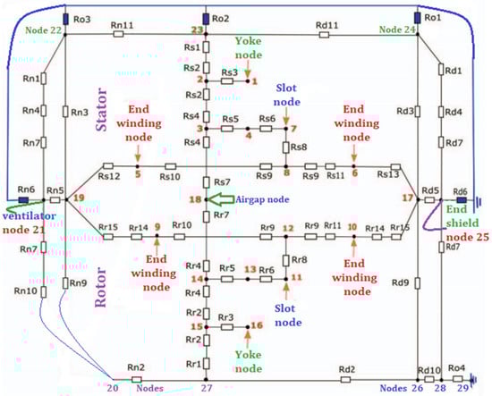
Figure 3.
Example of an LPTN model of a 37 kW IM [20].
The cooling system’s thermal parameters, such as conduction, radiation, convection thermal resistance, and flow resistance of forced convection heat transfer, are estimated with the help of Equations (3a)–(3d) [18].
where hR and hC are the radiation and convection heat transfer coefficient, respectively, represents the fluid density, L and A are the path length and path area, respectively.
In Han PW et al. [19] the LPTN model is used to find the temperature profile of a water-cooled-type IM and the result of simulation, see Table 1. Since the rear parts have few gaps, the temperature load at the rear end is high, compared to that of the front part.

Table 1.
Temperature distribution by thermal analysis [19].
3.2. Numerical Methods
3.2.1. Modelling and Analysis Using Finite Element Analysis
A fine-meshed model with the nodes and elements is examined for the changes along the dimensions using the popular FEA. The 2D and 3D thermal FEA could be performed using much available commercial software in steady and transient states. Results from both the LPTN model and FEA are alike to each other due to the reason that both of them are fed with common inputs. However, the major drawback of FEA is the processing time. FEA has its merits over LPTN when complex geometry has to be handled [21].
Xie et al. [22] gave temperature estimations on a 3D model of an enclosed fan-cooled IM. They observed the 3D thermal model of an IM at a healthy state when one bar is broken and when two adjacent bars are broken. Zhang Y et al. [23] use FEA to investigate the 3D coupled field FEM to find the temperature profile of an air-cooled IM. The increase in the temperature was found in the stator winding and squirrel cages majorly due to joules losses and heat released, as a result of conduction in solid and convection in air.
FEA software, AnSys Maxwell 2-D v.16, and AnSys Maxwell 3-D v.15, is considered to be one of the best for electromagnetics and is used to find the thermal characteristics in the transient state of the IM and the losses in power in the torque area in the steady-state [6]. It presents an investigation rise in IM when the effects of loading are taken into consideration. Software for FEA simulation, such as in [24], can be used to predict sources of thermal energy caused as a result of electromagnetic losses—the eddy currents and hysteresis in magnets and laminations and the heating due to joule heating in the windings. The major merits of FEA over others lie in its ability to predict the flow in regions, such as around the end windings, which is considered complex [25]. For comparison with the LPTN model, a partial FEA thermal analysis, Figure 4 [10].
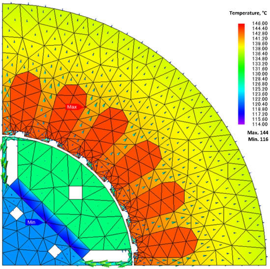
Figure 4.
Partial FEA model of thermal analysis [10].
3.2.2. Modelling and Analysis Using CFD Analysis
The temperature estimation with CFD is different when compared to the LPTN method, since the CFD analysis could reach higher accuracy against a structural analysis of a motor. The boundary conditions of heat transfer for the FEA model and lumped circuit input, simulations for predicting fluid flow characteristics, and optimizing the cooling methods, such as air-cooled water jackets, etc., could be determined with CFD analysis [26]. CFD is used for big motors and generators, since it has a major advantage over others when predicting flow in complex regions [18]. In [27], precise geometric sensitivities that affect the thermal flow characteristics are examined using Simcenter Star-CCM+ (a CFD tool) by performing finite volume analysis. Airflow rate of the external, as well as an internal fan, the rise of the volume-averaged temperature of the insulated windings, are found.
Jang JH et al. [28] analyze the temperature profiles of the motor and the cooling mechanism performance found using commercial software with FVM, and a semi-implicit method for the pressure-linked equations. The heat transfer equivalent and the boundary conditions of fluid flow in the FEA motor model and pumped approach are given by CFD calculation [18,29]. Roffi M et al. [30] use CFD simulation software to accelerate the designing of the impeller and optimize the aerodynamic process, as well as visualizing the fluid-air dynamics for different cooling fan designs for the IM. Conjugated heat transfer methods could be used to improve the results found after stimulation [8,31], where both the solid and fluid domains are modelled. The heat losses could be well-defined in the solid domains as volumetric sources found by electromagnetic simulations. Temperatures of the inlets and outlet, pressure changes, and volumetric flow rate are the inputs in the CFD method, similar to the material input in FEA [19,26].
3.3. Experimental Validation
Even though the LPTN model and numerical analysis provide very precise and accurate temperature profile predictions and thermal management, a certain degree of errors or inaccuracy always exists because of the model limitations, parameter deviation, various assumptions in equations and models, simple boundary conditions and so on. Thus, it is often mandatory to verify and calibrate the results through experimentation. There are generally two types of experimental validation methods: (i) experiments conducted to determine machine thermal parameters, and (ii) experiments to verify the results of simulation and analysis.
Temperature monitoring is done using direct thermal sensors by placing them on the end caps, windings, etc., [32,33]. Thermocouples, resistance thermometers, and thermistors are the most used thermal monitoring sensors. The principle on which thermocouples work is that a potential difference is created between two dissimilar metals, which increases with temperature. Quick response time, a broad range of measurements and simple configurations are its major merits. However, due to low signal strength, they are susceptible to electromagnetic interference. Thermistors are considered more accurate compared to thermocouples. The major merits of thermistor over thermocouple of simple geometry, small in size and low thermal mass. It is also susceptible to electromagnetic noises. In some cases where the sensors are difficult to place, infrared thermography is used as an indirect temperature measurement [34,35,36]. Figure 5 shows the infrared thermal image of an IM [35].
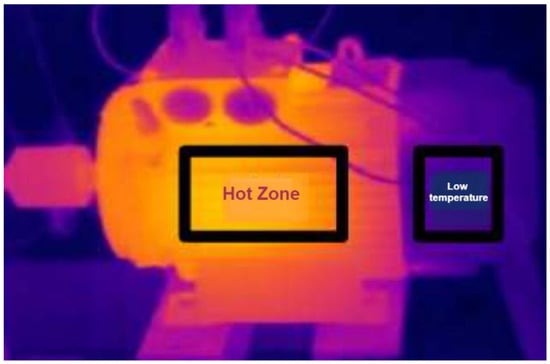
Figure 5.
Infrared image of a healthy IM with no load [35].
4. Various Cooling Strategies
4.1. Air Cooling Approach
Roffi et al. [30] compared many cooling strategies involving various designs in the fan, which includes the likes of standard centrifugal fans and some axial fans for the same base fan cover. The experimentation was conducted with an IE3 class 7.5 kW, 4 poles, 400 V squirrel caged IM at no and part loads. Table 2 provides the simulated outcomes for four dissimilar axial fan designs and Table 3 gives the experiment results of part load for the IM with four different cooling fan systems. Table 4 shows the respective fan and cover designs for Table 2 and Table 3. The inclusive efficacy improves unidirectional self-ventilated motors when fan power is reduced without changing the velocity of the air and the volumetric airflow. Henceforth, not affecting the motor operating temperatures.
Table 2.
Results of simulations for four diverse designs of axial fans [30].
Table 3.
Part-load experimental results with four different cooling fan systems [30].
Table 4.
Fan designs and the respective cover [30].
Moon et al. [27] numerically studied the characteristics of the thermal flow of an enclosed fan-cooled IM. The various configurations, including the fin, which is joined to the surface of the frame, frames embedded with air channels, air duct through the rotor core and fan cover, which enclosed the external fan, were incorporated and variations among them were studied. CFD analyses were performed and results were validated for accuracy through experimental tests, Figure 6. Based on the parametric studies, the level of cooling effect was raised to its maximum power density, and, as a result, the motor was developed: 2350 kW, 560 frames, 4 poles, 6 kV and 60 Hz.
Figure 6.
Results of increase in stator winding temperature [27].
Kim et al. [37] have studied the effects of air gap fans and the cooling of the winding of a large capacity IM using computational thermal coupled analysis to improve the accuracy of results. In this work, varying iron loss distribution model that considered the time and rotation period was included, Figure 7. The performance of different configurations with only front air gap fan, only rear-end air gap fan, and when both the sides had the air gap fan were compared to a scenario with no air gap fans. Results showed that the effect of vanishing stagnant flow near the gaps was due to the fact that the fan increases the flow rate distribution, Table 5. The average temperature in the IM declines with the growth in the average flow velocity in the cavity. This also led to the heat transfer coefficient increase by 31% at the surfaces of the windings and the air gaps by 90%. For a singular fan scenario, the fan at the rear end had improved by 36%, and in the case of the fan at the front end, this was only 35%.
Figure 7.
Schematic diagram of an IM with air gap fan [37].
Table 5.
Temperature distribution (a) without a fan; (b) with fan [37].
Zhang et al. [23] have studied temperature profile over air-cooled asynchronous IM by coupled field FEM approach. A fluid model was suggested, where all rotor parts are considered fluids with certain conditions. Due to the rotation of the rotor, Coriolis force and centrifugal forces are taken into account, since they have a huge influence. A new asynchronous motor is designed with a 6-phase, 8-poles and 200 kW capacity to validate the proposed methodology. The multi-fluid model showed positive agreement with the simulated and experimental results.
Kim et al. [38] to improve the existing thermal circuit’s model introduced a new thermal model (TNM) by compensating for the modelling of the heat transport by airflow. Thermal analysis was performed on an open-type air-cooled IM. A total number of 36 nodes for solid and fluid regions in the motor were chosen to build the thermal nexus model. In comparison to CFD and the experimental method, the thermal nexus model was able to show a 4% less error. Further, the cooling path analysis showed a 3% less error, compared to CFD. It was, hence, concluded that the developed model was handy in improving the design of the motor cooling system.
Hashish et al. [39] patented a new invention of an auxiliary cooling system for TEFC IM. The invention provided a buffet thermal shroud that was incorporated over the present motor housing cooling fins in a spaced manner. The tabs were aligned in the airflow channel amid the contrasting cooling fins, where they are in thermal and fluid communications with the cooling air-flow. The turbulence created in the cooling air-flow by the tabs or shroud fingers were able to increase convective heat transfer efficiency and contact time amid the cooling air and motor cooling fins. It was further stated that the present invention can be retrofitted on any IM quickly at the lowest possible cost and with relatively little effort.
4.2. Liquid Cooling Approach
Rehman et al. [40] conducted the 3D steady-state model investigation of a 90 kW IM with three different layouts of cooling jackets and four types of coolant flow passes. Four different water flows (5, 10, 20 and 30 LPM) were numerically studied. Maximum functioning temperature and pumping power were the key areas of focus in this investigation. The different configurations are shown in Figure 8 and Figure 9. The upper limit of the operating temperature for the design of the cooling jacket was set at 373 K. The highest temperature was observed to be in the stator winding due to intense heat loss from the winding loss. It was observed that the more the number of passes, the less the maximum temperature reached. Furthermore, the effect of varying the number of passes becomes less on increasing the passes beyond six, Table 6 and Table 7.
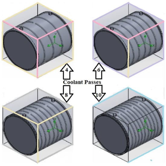
Figure 8.
Cooling jacket configuration with different number of passes [40].
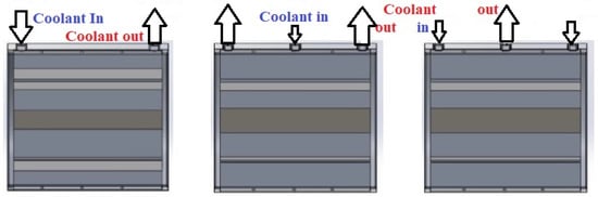
Figure 9.
Port configuration [40].
Table 6.
Maximum temperature versus flow rate for all the designed models [40].
Table 7.
Rate of temperature variation, with respect to the number of passes and coolant flow rate [40].
Han et al. [19] carried out the analysis of a high-speed water-cooled IM using LPTN methods. The heat transfer coefficients of the water jackets channel and interface amid the core of the stator and frame were an influential factor, since the motor was a water-cooled type. Further, from Table 8 it was observed that the temperature of the trailing part of the end winding was greater, in contrast to the front part, since it had a minute gap with the housing. The authors concluded by stating that if the important parameters, such as interface gap and heat conductivity of the materials are properly selected, accurate distribution of temperature can be achieved from the LPTN method.
Table 8.
Temperature distribution [19].
Satrústegui et al. [41] presented a thermal model of an IC71 IM with different design criteria for the water-cooled system. The key parameters that describe the water jacket and shaft were identified through the use of a validated thermal model and CFD simulation. The topology of the water jacket was analyzed and it was observed that with similar cooling areas, Figure 10. The topologies were classified based on the pressure drop introduced in the cooling system. Spiral water jackets were chosen as the preferred option for reducing the pressure drop but were the most complex to manufacture. Later, two parameters that had almost no influence were determined, which were the interspace of cooling ducts and the distance between the ducts and the stator stack. Finally, the influence of water in these cooling arrangements was analyzed using CFD techniques. The temperature of some parts of the motor reduced significantly due to the enhanced coefficient of heat transfer by the use of water.
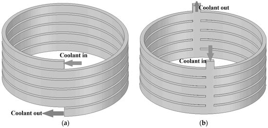
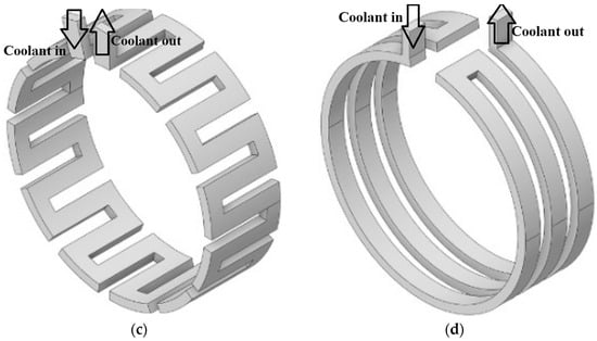
Figure 10.
(a) Spiral water jacket; (b) Bifurcated U-shaped water jacket; (c) Axial water jacket; (d) Dial water jacket [42,43].
Tanguy et al. [44] performed an experimental study on the oil cooling system for an electric motor. The focus of the study was to determine the influence of the oil temperature, rotation speed and oil flow rate on the cooling of the stator coil end cooling. The oil flow rate was changed between 40 and 360 L/h, the oil temperature between 50 °C to 75 °C and the speed between 0 to 4600 rpm. Different injection patterns, see Figure 11, were utilized to study the above factors, which have been summarized in Figure 12.
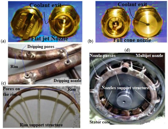
Figure 11.
Different oil flow patterns: (a) Flat jet nozzle (FJN); (b) Full cone nozzle (FCN); (c) Dripping nozzle; (d) MultiJet nozzle [42].
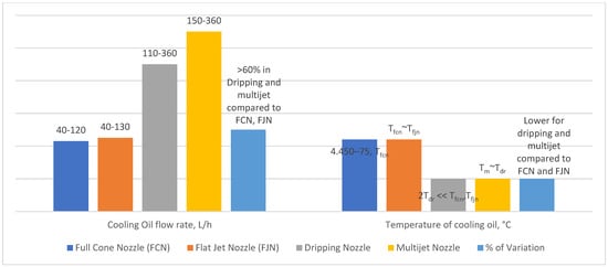
Figure 12.
Experimental testing conditions [44].
The author concluded that oil, even in restricted amounts, had greatly improved the global heat transfer, in contrast to air-based cooling only. The dripping injector proved to be highly effective as the oil is injected with a higher flow rate at the top region and the end windings. This is followed by nozzle injection in which the efficiency was similar for both types of nozzles. The jet seemed to be ineffective in the cooling performance. The oil flow rate remained the major factor in improving global efficacy for any configuration, Figure 11.
Rippel [45] patented a new method of a liquid cooling system called transverse lamination cooling wherein the coolant flows transversely through a narrow region formed by apertures in every other magnetic lamination. The new invention greatly improved the cooling performance of the stator winding, as well as the rotor winding.
Recent advancements in the field of dimple cooling geometry have opened new opportunities for the utilization of such geometries in liquid-cooled induction motors. Qian et al. [46] conducted the numerical simulation of both simple dimples with dissimilar geometries and the complete dimple jacketed heat exchanger with diverse dimple measures. It was observed that the dimples could enhance the heat transfer efficiency in contrast to the conventional jacketed heat exchanger. Pan et al. [47] aimed to study the numerical analysis and comparison of fluid flow and heat transfer characteristics of a microchannel heat exchanger with diverse re-entrant cavities. It was concluded that the heat transfer efficacy of microchannel heat exchangers with re-entrant cavities is improved, and the pressure drop is lower. The highest heat transfer efficacy comes from a microchannel heat exchanger with trapezoidal-shaped cavities, whereas the smallest pressure drop comes from a microchannel heat exchanger with fan-shaped cavities. Fazli et al. [48] aimed to expect the turbulent flow and heat transfer through diverse channels with periodic dimple walls. The efficacy of several low-Re k-turbulence models in predicting local heat transfer coefficient is assessed more explicitly. The nonlinear k-ε model forecasts a bigger whirly bubble inside the dimple with more impingement and upward flow than the zonal and linear k-ε models, according to the numerical predictions. Heat transport estimates inside the dimples and their rear rim improve when the linear k-ε model is used. The nonlinear k-ε function, on the other hand, yields the most accurate thermal forecasts.
Apart from the cooling structures, there also has been developed in the field of cooling fluids apart from the conventional water and oil. Deriszadeh et al. [49] investigate the possibility of directly cooling traction motors in the car industry using a liquid medium. As a coolant, a mixture of ethylene glycol and water with different volume fractions is utilized. Thermal analyses of the cooling system are carried out using CFD and 3D turbulent fluid motion analysis. During research and modelling, it was discovered that increasing the number of fluids turning channels, the volume combination of ethylene glycol, and the Reynolds number increases the heat transfer coefficient. When the number of rotations was eight, the volume mixing ratio of ethylene glycol to water was 60:40 and Reynolds no. 5000, the highest performance was recorded. Ijaz et al. [50] carried out research comprising a simulation-based evaluation of graphene-doped nano-coolant thermal properties in an automobile radiator. To explore the impact of graphene oxide (GO) nanoparticles doped in a base fluid (water) as a nano coolant for a car radiator’s temperature reduction over the tube length and efficacy. As the concentration of GO nanoparticles by volume increases, a significant temperature reduction is observed. Temperature drops of 9.68 K, 10.89 K and 11.9 K are typical for 6%, 8% and 10% of the GO nanoparticles, respectively. The efficacy of the radiator rises in proportion to the percentage increase in nanoparticle addition. Mukherjee et al. [51] studied the value of k of commercial engine coolant-based SiO2 nanofluids utilizing a unique sonic velocity measuring methodology. This was performed, considering k is a vital constraint to define the heat transfer efficacy. Nanofluids were made by dispersing SiO2 nanoparticles in engine coolant at five distinct mass concentrations: 0.01%, 0.05%, 0.10%, 0.50% and 1%. The temperature rise was more effective than the rise in nanofluid concentration, according to these findings. At 65 °C, a nano-coolant concentration of 1% demonstrated a maximum increase in k of 21.083%. Ultimately, in this work, a novel mathematical correlation was created to accurately estimate the value of k of engine coolant-based SiO2 nanofluids.
4.3. Heat Pipes/Plates Cooling Approach
N. Putra et al. [52] explored on the heat management of electric motors using L-shaped heat pipes. The heat pipes were located on the surface of the motor housing, Figure 13. The L-shaped flat heat pipes with 154 mm evaporator section and 34 mm condenser section with heat sinks were made of copper tubes. The heat sinks were used to enable fast heat transfer to the surrounding area. For uniform heat generation, a cartridge heater was positioned inside the motor housing. The heat generation process was regulated by an AC voltage regulator. The experiment was conducted for five sets of heat loads, namely 30 W, 60 W, 90 W, 120 W and 150 W. Further, the experiment was conducted without the L-shaped flat heat pipes to increase or decrease in performance. The results indicated that on using the L-shaped heat pipes, the temperature of both the inner and outer surface reduced to a greater, Table 9. For instance, at a heat load of 150 W, the utilization of the L-shaped flat heat pipes reduced the inner and outer surface temperature by 34.6 °C and 33.8 °C correspondingly, as compared to without the heat pipes. To achieve a high motor performance and high power density, various effective cooling schemes have to be incorporated. Cooling schemes aiming to bring down the temperatures at the hot spots and raise motor thermal efficiency have to be carefully adopted. Hence, an IM system with novel motor topologies, geometrical parameters, design and materials would greatly affect the electrical/electromagnetic performance of the system, Figure 14. Out of all the cooling schemes, air-cooling is the cheapest. Liquid cooling is a very effective strategy but complex geometry, pumping and also the addition of nanoparticles makes it more expensive, compared to all the cooling schemes. Heat pipe cooling is effective for motor housing cooling but compared to liquid cooling it is cheaper because this scheme is mostly an add-on to the existing air cooling strategy.
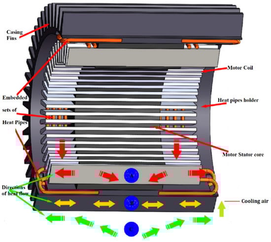
Figure 13.
Schematic of L-shaped flat heat pipes mounted on an electric motor model [53].
Table 9.
Effect of heat pipe implementation [52].
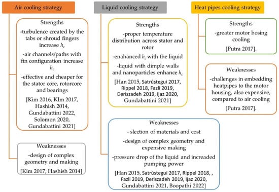
Figure 14.
Cooling schemes for the components of heat sources [37,38,39,40,41,44,45,46,47,48,49,50,51,52,53,54,55,56,57].
5. Future Scope
A thorough analysis of all the available literature on thermal analysis has pointed out a common conclusion that liquid cooling systems are more advantageous when it comes to dealing with high heat loads due to their high thermal conductivity and highly turbulent flow, which increase the heat transfer characteristics. Additionally, the use of different coolants can further improve the cooling aspects of these systems. The use of mixtures of two or more coolants, such as water and ethylene glycol, has made it possible to obtain enhanced cooling characteristics. Moreover, the use of the nanoparticles in the coolant has opened up new avenues for the development of safe and improved heat rejection strategies. However, the increased use of power to pump around the coolant liquid requires significant attention, since it decreases the net output power. The recent advancement in dimple cooling geometries has led to improved cooling rates with just minor changes to the surface of the heat exchange region. This can prove to be instrumental in creating thermal management strategies. When compared to a liquid cooling system, the air-cooled system consumes less power but is not as efficient as liquid cooling systems when dealing with high heat loads. The utilization of heat pipes in the thermal management of large-capacity motors have not received the required attention needed. If used with an appropriate coolant, the heat pipes strategy has the potential to reuse the obtained low-grade heat for purposes requiring low heating, thereby increasing the overall efficiency of the system. Hence, is suggested that an integrated approach can be adopted while dealing with large-capacity motors. This system can utilize two or more cooling strategies together to improve the overall dynamics of the induction motor.
6. Summary
The thermal management and analysis of an induction motor play an important role to determine the performance and consistency. This paper carefully covers diverse characteristics related to induction motor heat management and analysis to identify the major hotspots and deal with them appropriately. Different loss generation in the induction motor is provided when it is shown how copper, iron, and mechanical losses affect the heat load on an induction motor. The study provides various methods of thermal analysis for drawing a thermal profile of an induction motor to choose an appropriate cooling strategy. The thermal methods provide show the merits and demerits of LPTN, numerical approaches (i.e., in the CFD) and experimental validation. Furthermore, this paper also presents various cooling strategies for the readers or researchers to choose from, which includes their merits and demerits. The air-cooled systems have been carefully analyzed and compared with the liquid-cooled systems. Moreover, different coolant fluids, which have gained traction in recent times have also been discussed. New strategies, such as dimple cooling geometries, have also been studied to provide necessary insight into the upcoming technologies in the field of thermal management. The future scope is being provided to serve as grounds for researchers and machine designers working in a related field.
Author Contributions
Conceptualization, S.M., R.D.P.B., E.G. and A.M.; methodology S.M. and R.D.P.B.; validation, E.G. and A.M.; formal analysis, S.M., R.D.P.B. and E.G.; investigation, S.M., R.D.P.B., E.G. and A.M.; resources, E.G. and A.M.; writing—original draft preparation, S.M., R.D.P.B. and E.G.; writing—review and editing, E.G. and A.M.; visualization, A.M.; supervision, E.G. All authors have read and agreed to the published version of the manuscript.
Funding
This research is supported by Bialystok University of Technology project (WZ/WE-IA/4/2020) and financed from a subsidy provided by the Polish Ministry of Science and Higher Education.
Institutional Review Board Statement
Not applicable.
Informed Consent Statement
Not applicable.
Acknowledgments
The authors are thankful to the management of Vellore Institute of Technology, India, and the Faculty of Electrical Engineering, Bialystok University of Technology, Poland, for their continued support.
Conflicts of Interest
The authors state that they have no known competing financial interest or personal ties that might have influenced the research presented in this study.
References
- Hannan, M.A.; Ali, J.A.; Mohamed, A.; Hussain, A. Optimization techniques to enhance the performance of IM drives: A review. Renew. Sustain. Energy Rev. 2018, 81, 1611–1626. [Google Scholar] [CrossRef]
- Kumar, R.H.; Iqbal, A.; Lenin, N.C. Review of recent advancements of direct torque control in IM drives—A decade of progress. IET Power Electron. 2017, 11, 1–5. [Google Scholar] [CrossRef]
- Glowacz, A.; Glowacz, Z. Diagnosis of the three-phase IM using thermal imaging. Infrared Phys. Technol. 2017, 81, 7–16. [Google Scholar] [CrossRef]
- Zhao, K.; Cheng, L.; Zhang, C.; Nie, D.; Cai, W. IMs lifetime expectancy analysis subject to regular voltage fluctuations. In Proceedings of the 2017 IEEE Electrical Power and Energy Conference (EPEC), Saskatoon, SK, Canada, 22–25 October 2017; IEEE: New York, NY, USA, 2017; pp. 1–6. [Google Scholar]
- Staton, D. Thermal analysis of traction motors. In Proceedings of the 2014 IEEE Transportation Electrification Conference and Expo (ITEC), Detroit, MI, USA, 15–18 June 2014; IEEE: New York, NY, USA; pp. 1–139. [Google Scholar]
- Seong, K.H.; Hwang, J.; Shim, J.; Cho, H.W. Investigation of temperature rise in an IM considering the effect of loading. IEEE Trans. Magn. 2014, 50, 1–4. [Google Scholar] [CrossRef]
- Ahmed, F.; Roy, P.; Towhidi, M.; Feng, G.; Kar, N.C. CFD and LPTN Hybrid Technique to Determine Convection Coefficient in End-winding of TEFC IM with Copper Rotor. In Proceedings of the IECON 2019-45th Annual Conference of the IEEE Industrial Electronics Society, Lisbon, Portugal, 14–17 October 2019; IEEE: New York, NY, USA; Volume 1, pp. 939–944. [Google Scholar]
- Schrittwieser, M.; Marn, A.; Farnleitner, E.; Kastner, G. Numerical analysis of heat transfer and flow of stator duct models. IEEE Trans. Ind. Appl. 2013, 50, 226–233. [Google Scholar] [CrossRef]
- Huang, Z.; Marquez, F.; Alakula, M.; Yuan, J. Characterization and application of forced cooling channels for traction motors in HEVs. In Proceedings of the 2012 XXth International Conference on Electrical Machines, Marseille, France, 2–5 September 2012; IEEE: New York, NY, USA; pp. 1212–1218. [Google Scholar]
- Yang, Y.; Bilgin, B.; Kasprzak, M.; Nalakath, S.; Sadek, H.; Preindl, M.; Cotton, J.; Schofield, N.; Emadi, A. Thermal management of electric machines. IET Electr. Syst. Transp. 2016, 7, 104–116. [Google Scholar] [CrossRef]
- Lu, B.; Habetler, T.G.; Harley, R.G. A nonintrusive and in-service motor-efficiency estimation method using air-gap torque with considerations of condition monitoring. IEEE Trans. Ind. Appl. 2008, 44, 1666–1674. [Google Scholar] [CrossRef]
- Nalakath, S.; Preindl, M.; Bilgin, B.; Cheng, B.; Emadi, A. Modeling and analysis of AC resistance of a permanent magnet machine for online estimation purposes. In Proceedings of the 2015 IEEE Energy Conversion Congress and Exposition (ECCE), Montreal, QC, Canada, 20–24 September 2015; IEEE: New York, NY, USA; pp. 314–319. [Google Scholar]
- Demetriades, G.D.; De La Parra, H.Z.; Andersson, E.; Olsson, H. A real-time thermal model of a permanent-magnet synchronous motor. IEEE Trans. Power Electron. 2009, 25, 463–474. [Google Scholar] [CrossRef]
- Zhang, Y.; Cheng, M.C.; Pillay, P. Magnetic characteristics and excess eddy current losses. In Proceedings of the 2009 IEEE Industry Applications Society Annual Meeting, Houston, TX, USA, 4–8 October 2009; IEEE: New York, NY, USA; pp. 1–5. [Google Scholar]
- Ridge, A.; McMahon, R.; Kelly, H.P. Detailed thermal modelling of a tubular linear machine for marine renewable generation. In Proceedings of the 2013 IEEE International Conference on Industrial Technology (ICIT), Cape Town, South Africa, 25–27 February 2013; IEEE: New York, NY, USA; pp. 1886–1891. [Google Scholar]
- Zhang, D.; Dai, H.; Zhao, H.; Wu, T. A fast identification method for rotor flux density harmonics and resulting rotor iron losses of inverter-fed induction motors. IEEE Trans. Ind. Electron. 2017, 65, 5384–5394. [Google Scholar] [CrossRef]
- Wang, R.-J.; Heyns, G.C. Thermal analysis of a water-cooled interior permanent magnet traction machine. In Proceedings of the IEEE International Conference on Industrial Technology (ICIT), Cape Town, South Africa, 25–27 February 2013; IEEE: New York, NY, USA; pp. 416–421. [Google Scholar]
- Boglietti, A.; Cavagnino, A.; Staton, D.; Shanel, M.; Mueller, M.; Mejuto, C. Evolution and modern approaches for thermal analysis of electrical machines. IEEE Trans. Ind. Electron. 2009, 56, 871–882. [Google Scholar] [CrossRef]
- Han, P.W.; Choi, J.H.; Kim, D.J.; Chun, Y.D.; Bang, D.J. Thermal analysis of high-speed IM by using lumped-circuit parameters. J. Electr. Eng. Technol. 2015, 10, 2040–2045. [Google Scholar] [CrossRef]
- Nair, D.G.; Jokinen, T.; Arkkio, A. Coupled analytical and 3D numerical thermal analysis of a TEFC IM. In Proceedings of the 2015 18th International Conference on Electrical Machines and Systems (ICEMS), Pattaya, Thailand, 25–28 October 2015; IEEE: New York, NY, USA; pp. 103–108. [Google Scholar]
- Gundabattini, E.; Kuppan, R.; Solomon, D.G.; Kalam, A.; Kothari, D.P.; Bakar, R.A.A. review on methods of finding losses and cooling methods to increase the efficiency of electric machines. Ain Shams Eng. J. 2020, 12, 497–505. [Google Scholar] [CrossRef]
- Xie, Y.; Wang, Y. 3D temperature field analysis of the IMs with broken bar fault. Appl. Therm. Eng. 2014, 66, 25–34. [Google Scholar] [CrossRef]
- Zhang, Y.; Ruan, J.; Huang, T.; Yang, X.; Zhu, H.; Yang, G. Calculation of temperature rise in air-cooled IMs through 3-D coupled electromagnetic fluid-dynamical and thermal finite-element analysis. IEEE Trans. Magn. 2012, 48, 1047–1050. [Google Scholar] [CrossRef]
- Endert, F.; Heidrich, T.; Schwalbe, U.; Szalai, T.; Ivanov, S.D. Effects of current displacement in a PMSM traction drive with single turn coils. In Proceedings of the 2013 International Electric Machines & Drives Conference, Chicago, IL, USA, 12–15 May 2013; IEEE: New York, NY, USA; pp. 160–165. [Google Scholar]
- Mugglestone, J.; Pickering, S.J.; Lampard, D. Effect of geometric changes on the flow and heat transfer in the end region of a TEFC IM. In Proceedings of the 1999. Ninth International Conference on Electrical Machines and Drives, 9 September 1999; IET: London, UK; pp. 40–44. [Google Scholar]
- Srinivas, K.N.; Arumugam, R. Analysis and characterization of switched reluctance motors: Part II. Flow, thermal, and vibration analyses. IEEE Trans. Magn. 2005, 41, 1321–1332. [Google Scholar] [CrossRef]
- Moon, S.H.; Jung, Y.H.; Kim, K.W. Numerical investigation on thermal-flow characteristics of a totally enclosed fan cooled IM. In Proceedings of the 2016 XXII International Conference on Electrical Machines (ICEM), Lausanne, Switzerland, 1–4 September 2016; IEEE: New York, NY, USA; pp. 1928–1933. [Google Scholar]
- Jang, J.H.; Chiu, H.C.; Yan, W.M.; Tsai, M.C.; Wang, P.Y. Numerical study on electromagnetics and thermal cooling of a switched reluctance motor. Case Stud. Therm. Eng. 2015, 6, 16–27. [Google Scholar] [CrossRef]
- Boglietti, A.; Nategh, S.; Carpaneto, E.; Boscaglia, L.; Scema, C. An optimization method for cooling system design of traction motors. In Proceedings of the 2019 IEEE International Electric Machines & Drives Conference (IEMDC), San Diego, CA, USA, 12–15 May 2019; IEEE: New York, NY, USA; pp. 1210–1215. [Google Scholar]
- Roffi, M.; Ferreira, F.J.; De Almeida, A.T. Comparison of different cooling fan designs for electric motors. In Proceedings of the 2017 IEEE International Electric Machines and Drives Conference (IEMDC), Miami, FL, USA, 21–24 May 2017; IEEE: New York, NY, USA; pp. 1–7. [Google Scholar]
- Shanel, M.; Pickering, S.J.; Lampard, D. Conjugate heat transfer analysis of a salient pole rotor in an air cooled synchronous generator. In Proceedings of the IEMDC’03. IEEE International Electric Machines and Drives Conference, Madison, WI, USA, 1–4 June 2003; IEEE: New York, NY, USA; Volume 2, pp. 737–741. [Google Scholar]
- Yang, Y.; Schofield, N.; Emadi, A. Double-rotor switched reluctance machine design, simulations, and validations. IET Electr. Syst. Transp. 2016, 6, 117–125. [Google Scholar] [CrossRef]
- Cavagnino, A.; Tenconi, A.; Vaschetto, S. Experimental characterization of a belt-driven multiphase induction machine for 48-V automotive applications: Losses and temperatures assessments. IEEE Trans. Ind. Appl. 2015, 52, 1321–1330. [Google Scholar]
- Singh, G.; Kumar, T.A.; Naikan, V.N. Fault diagnosis of IM cooling system using infrared thermography. In Proceedings of the 2016 IEEE 6th International Conference on Power Systems (ICPS), Delhi, India, 4–6 March 2016; IEEE: New York, NY, USA; pp. 1–4. [Google Scholar]
- Balakrishnan, G.K.; Yaw, C.T.; Koh, S.P.; Abedin, T.; Raj, A.A.; Tiong, S.K.; Chen, C.P. A Review of Infrared Thermography for Condition-Based Monitoring in Electrical Energy: Applications and Recommendations. Energies 2022, 15, 6000. [Google Scholar] [CrossRef]
- Stipetic, S.; Kovacic, M.; Hanic, Z.; Vrazic, M. Measurement of excitation winding temperature on synchronous generator in rotation using infrared thermography. IEEE Trans. Ind. Electron. 2011, 59, 2288–2298. [Google Scholar] [CrossRef]
- Kim, C.; Lee, K.S.; Yook, S.J. Effect of air-gap fans on the cooling of windings in a large-capacity, high-speed IM. Appl. Therm. Eng. 2016, 100, 658–667. [Google Scholar] [CrossRef]
- Kim, C.; Lee, K.S. Thermal nexus model for the thermal characteristic analysis of an open-type air-cooled IM. Appl. Therm. Eng. 2017, 112, 1108–1116. [Google Scholar] [CrossRef]
- Hashish, E. IM Auxiliary Cooling System. United States Patent US 8,912,695, 16 December 2014. [Google Scholar]
- Rehman, Z.; Seong, K. Three-D numerical thermal analysis of electric motor with cooling jacket. Energies 2018, 11, 92. [Google Scholar] [CrossRef]
- Satrústegui, M.; Martinez-Iturralde, M.; Ramos, J.C.; Gonzalez, P.; Astarbe, G.; Elosegui, I. Design criteria for water cooled systems of induction machines. Appl. Therm. Eng. 2017, 114, 1018–1028. [Google Scholar] [CrossRef]
- Le, W.; Lin, M.; Lin, K.; Liu, K.; Jia, L.; Yang, A.; Wang, S. A Novel Stator Cooling Structure for Yokeless and Segmented Armature Axial Flux Machine with Heat Pipe. Energies 2021, 14, 5717. [Google Scholar] [CrossRef]
- Wu, S.; Zhou, J.; Zhang, X.; Yu, J. Design and Research on High Power Density Motor of Integrated Motor Drive System for Electric Vehicles. Energies 2022, 15, 3542. [Google Scholar] [CrossRef]
- Davin, T.; Pellé, J.; Harmand, S.; Yu, R. Experimental study of oil cooling systems for electric motors. Appl. Therm. Eng. 2015, 75, 1–13. [Google Scholar] [CrossRef]
- Rippel, W.E.; Rippel, E.E. Im with Transverse Liquid-Cooled Rotor and Stator. United States Patent US 9,985,500, 29 May 2018. [Google Scholar]
- Qian, J.Y.; Wu, Z.; Zhang, Q.K.; Jin, Z.J.; Sunden, B.A. Heat transfer analysis on dimple geometries and arrangements in dimple jacketed heat exchanger. Int. J. Numer. Methods Heat Fluid Flow 2019, 29, 2775–2791. [Google Scholar] [CrossRef]
- Pan, M.; Wang, H.; Zhong, Y.; Fang, T.; Zhong, X. Numerical simulation of the fluid flow and heat transfer characteristics of microchannel heat exchangers with different reentrant cavities. Int. J. Numer. Methods Heat Fluid Flow 2019, 29, 4334–4348. [Google Scholar] [CrossRef]
- Fazli, M.; Raisee, M. Computation of flow and heat transfer through channels with periodic dimple/protrusion walls using low-Reynolds number turbulence models. Int. J. Numer. Methods Heat Fluid Flow 2019, 29, 1178–1207. [Google Scholar] [CrossRef]
- Deriszadeh, A.; de Monte, F.; Villani, M.; Di Leonardo, L. Hydrothermal Performance of Ethylene Glycol and Water Mixture in a Spiral Channel for Electric Motor Cooling. In Proceedings of the 2019 21st European Conference on Power Electronics and Applications (EPE’19 ECCE), Genova, Italy, 3–5 September 2019. [Google Scholar]
- Ijaz, H.; Raza, H.; Gohar, G.A.; Ullah, S.; Akhtar, A.; Imran, M. Effect of graphene oxide doped nano coolant on temperature drop across the tube length and effectiveness of car radiator–A CFD study. Therm. Sci. Eng. Progress 2020, 20, 100689. [Google Scholar] [CrossRef]
- Mukherjee, S.; Halder, T.; Ranjan, S.; Bose, K.; Mishra, P.C.; Chakrabarty, S. Effects of SiO2 nanoparticles addition on performance of commercial engine coolant: Experimental investigation and empirical correlation. Energy 2021, 230, 120913. [Google Scholar] [CrossRef]
- Putra, N.; Ariantara, B. Electric motor thermal management system using L-shaped flat heat pipes. Appl. Therm. Eng. 2017, 126, 1156–1163. [Google Scholar] [CrossRef]
- Gundabattini, E.; Mystkowski, A.; Idzkowski, A.; R., R.S.; Solomon, D.G. Thermal Mapping of a High-Speed Electric Motor Used for Traction Applications and Analysis of Various Cooling Methods—A Review. Energies 2021, 14, 1472. [Google Scholar] [CrossRef]
- Gundabattini, E.; Mystkowski, A. Review of air-cooling strategies, combinations and thermal analysis (experimental and analytical) of a permanent magnet synchronous motor. Proc. Inst. Mech. Eng. Part C J. Mech. Eng. Sci. 2022, 236, 655–668. [Google Scholar] [CrossRef]
- Solomon, D.G.; Greco, A.; Masselli, C.; Gundabattini, E.; Rassiah, R.S.; Kuppan, R. A review on methods to reduce weight and to increase efficiency of electric motors using lightweight materials, novel manufacturing processes, magnetic materials and cooling methods. Ann. De Chim.-Sci. Des Matériaux 2020, 44, 1–14. [Google Scholar] [CrossRef]
- Gundabattini, E.; Mystkowski, A.; Raja Singh, R.; Gnanaraj, S.D. Water cooling, PSG, PCM, Cryogenic cooling strategies and thermal analysis (experimental and analytical) of a Permanent Magnet Synchronous Motor: A review. Sādhanā 2021, 46, 3. [Google Scholar] [CrossRef]
- Boopathi, N.G.; Muthuraman, M.S.; Palka, R.; Wardach, M.; Prajzendanc, P.; Gundabattini, E.; Rassiah, R.S.; Solomon, D.G. Modeling and Simulation of Electric Motors Using Lightweight Materials. Energies 2022, 15, 5183. [Google Scholar] [CrossRef]


Publisher’s Note: MDPI stays neutral with regard to jurisdictional claims in published maps and institutional affiliations. |
© 2022 by the authors. Licensee MDPI, Basel, Switzerland. This article is an open access article distributed under the terms and conditions of the Creative Commons Attribution (CC BY) license (https://creativecommons.org/licenses/by/4.0/).