1. Introduction
The analysis of the phenomena occurring in induction machines and synchronous machines is carried out using circuit models [
1,
2,
3,
4] as well as field-circuit models [
5,
6]. Comprehensive consideration of all phenomena occurring in electrical machines is possible in the field-circuit model [
7,
8,
9,
10], based on the finite element method. In this model, the nonlinear partial differential equations of the electromagnetic field are simultaneously solved with the Kirchhoff equations of electrical circuits and the equation of motion. However, the use of field-circuit models is limited due to the long computation times and, thus, the need to use computers with large computing power. For these reasons, circuit models are still often used in the analysis of dynamic states of electrical machines.
The parameters of the equivalent circuit model may be determined by measurement or in a computational manner using the machine design data. In the classic model, in which one equivalent circuit in the rotor is assumed, the electromagnetic parameters are determined via design calculations [
1,
11] or by measurement of the no-load and of the locked rotor test [
12]. The use of classical models in the dynamic-state analysis leads to significant discrepancies between the measured waveforms and the results obtained from computer simulations [
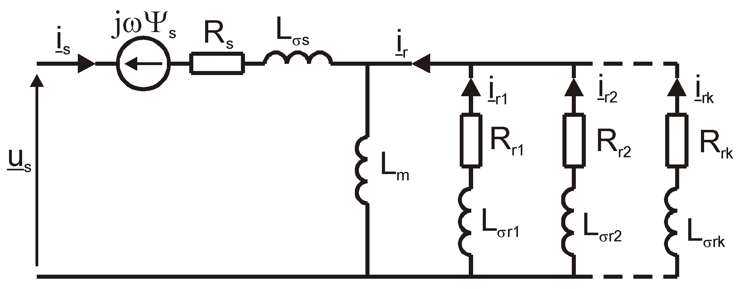
13]. Particularly large errors occur in high-power squirrel cage induction machines, in which there is a skin effect in the rotor cage bars, and in induction and synchronous machines with a solid rotor. Therefore, it is necessary to use higher-order circuit models [
14,
15] that more accurately account for electromagnetic phenomena occurring in the solid rotor of induction and synchronous machines. In these models, the action of eddy currents in the solid rotor of the machine is represented by a greater number of equivalent circuits in the form of two-terminal RL networks. To achieve the required approximation accuracy, a sufficiently large number of rotor equivalent circuits must be used, but then numerical identification of the parameters of the equivalent scheme is very difficult. An alternative solution [
16,
17,
18], presented in this paper, is to represent the skin effect in a solid rotor by means of resistance and inductance with fixed values and fractional-order inductance depending on the frequency of induced eddy currents. This model more accurately reflects the physical phenomena occurring in a solid rotor. In the classical model with four equivalent circuits, the number of parameters to be identified is nine. However, for the noninteger order model, the number of identified parameters is five, which is an advantage of using this model. Physical phenomena occurring in ferromagnetic elements of electrical machines or in the rotor cage bars of induction or synchronous machines can be described using fractional-order differential calculus [
19,
20,
21,
22]. The fractional-order operational inductance in the frequency domain represents the impedance whose resistance and inductance are a function of the frequency of the eddy current induced in the solid rotor of the machine. Fractional differential calculus in the analysis of transient states of synchronous machines with a solid rotor was already used in the 1970s. The paper [
23] presents an analysis of the transient states of a solid-rotor turbogenerator, where the rotor circuit was represented by the fractional-order operational inductance. In order to more accurately reproduce the skin effect in ferromagnetic elements or in the bars of the rotor cage, hybrid elements should be used [
24,
25,
26]. These elements are a series connection of integer and noninteger order elements. The equivalent circuit of a coil with ferromagnetic core in paper [
24] as well as the equivalent circuit of the rotor cage in paper [
25] are shown as a series connection of resistance and fractional order inductance.Based on a simplified analysis of the electromagnetic field, using the expansion of the Bessel function into the Taylor series, it was shown in [
26] that the solid-rotor circuit of a synchronous machine can be replaced by the resistance and inductance with lumped constants and the fractional inductance.
Applying the Laplace transform to a mathematical model containing fractional-order inductances is possible in the analysis of transient states of induction and synchronous machines only at a constant rotational speed. Then, a model in the form of operational transmittances is obtained. The conversion from the operational transfer function form to the time form for the fractional-order operational transmittances is difficult. In the paper [
27], for the operational transmittance containing fractional-order derivatives (the coefficients of the polynomial of the numerator and denominator of the Laplace operator p are multiples of 0.5), the field current waveform of a synchronous generator at a sudden short-circuit was determined, using the error function erfc of the complex argument. On the other hand, the analysis of the dynamic states of induction and synchronous machines with the use of a fractional-order equivalent circuit model for a variable rotational speed of the rotor is performed using the Grünwald–Letnikow method to solve equations with fractional-order derivatives [
19,
20].
The parameters of the equivalent circuit of induction and synchronous machines can be identified on the basis of the stator current, rotational speed or torque waveforms registered in the dynamic states [
15,
17,
28]. These parameters are determined by minimizing the mean-square error between the measured waveforms and those calculated using the simulation model.
Among the many different methods of determining the parameters of the equivalent circuit, the methods of determining the parameters based on measurements made at the machine standstill deserve special attention [
29,
30,
31,
32]. These methods require supplying the machine’s stator windings with a direct voltage-dc decay current test [
31,
32] or with single-phase sinusoidal voltage with an adjustable frequency–standstill frequency response test (SSFR) [
29,
30]. The standstill frequency response test, in which the frequency characteristics of spectral inductances are determined on the basis of measurements or machine design data, turned out to be particularly useful. By approximating these characteristics, the parameters are determined by the multiloop equivalent circuit with lumped constant parameters R and L or the equivalent circuit with fractional impedance as a function of the frequency of the eddy currents induced in the rotor circuit.
This article consists of five chapters and is organized as follows. In the Introduction, the method of presenting the electric circuits of the rotor in the equivalent circuit of an induction machine and the methods of identifying the parameters of induction machines are discussed. The second chapter presents a multicircuit model of an induction machine and a circuit model with a fractional rotor impedance. The next chapter describes the method of determining the parameters of the equivalent circuit of an induction machine. The parameters of the equivalent circuit for the fractional impedance of the rotor were determined by the standstill frequency response test. The frequency characteristics of the complex spectral inductances were calculated from the electromagnetic field distribution using the finite element method. The calculations of the magnetic field distribution were carried out by forcing a sinusoidal current with a frequency of 0 ÷ 1000 Hz in two stator phases connected in series. By approximating the magnitude and phase characteristics of the spectral inductances with the functions of the fractional order of the Laplace operator p, the parameters of the equivalent circuit were calculated. The fourth chapter discusses the simulation of the dynamic states of a solid-rotor induction motor. The integration of differential equations with integer order derivatives was performed using the Euler extrapolation algorithm. On the other hand, the Grünwald–Letnikov method was used for differential equations containing derivatives of the fractional-order. The fifth chapter presents the steady state of a solid-rotor induction motor. On the basis of the stator spectral inductance Ls(jω) determined from the electromagnetic field distribution, the stator current and the electromagnetic torque in the slip range from 0 to 1 were calculated. These values were compared with the characteristics obtained on the basis of the equivalent circuit and, in the case of the electromagnetic torque, with the mechanical characteristics determined directly from the transient state during the reversal of the induction motor. A good agreement of the results was obtained, which proves the correct identification of the parameters and the correctness of the calculations of the dynamic states of the induction motor with a solid rotor.
3. Identification of the Parameters of the Equivalent Circuit
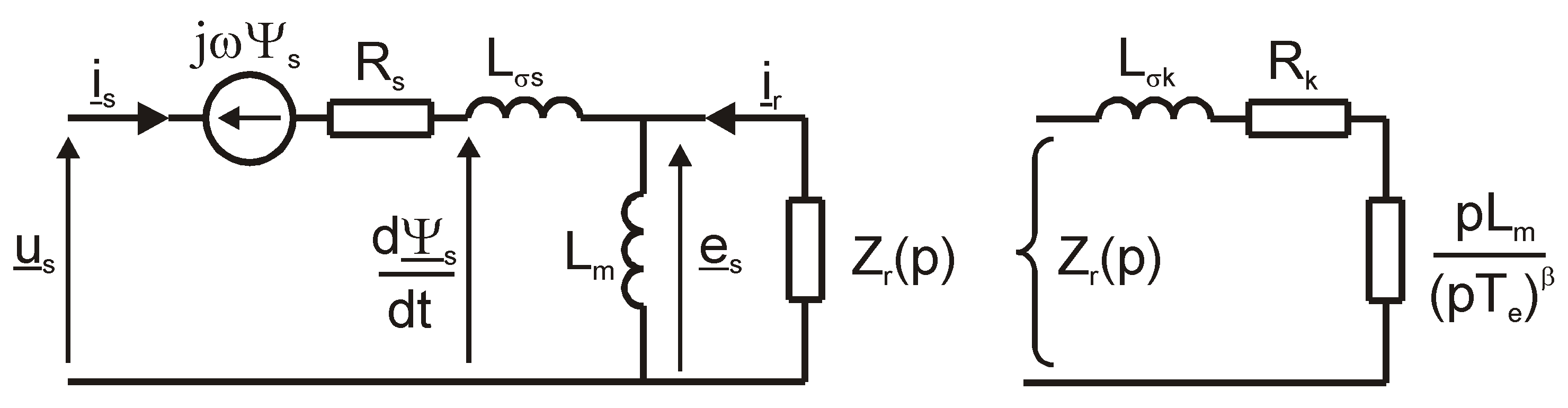
The equivalent circuit in
Figure 2 forms the basis of the stator operational inductance circuit shown in
Figure 3.
The following relationship is formed from this circuit
where: L
i(p)—internal operational inductance, where
Taking into account the dependence (6), the stator operator inductance L
s(p) will take the form
Substituting the Laplace operator p in relation (15) for the operator p = jω, the frequency characteristics of the spectral inductance Ls(jω) are obtained.
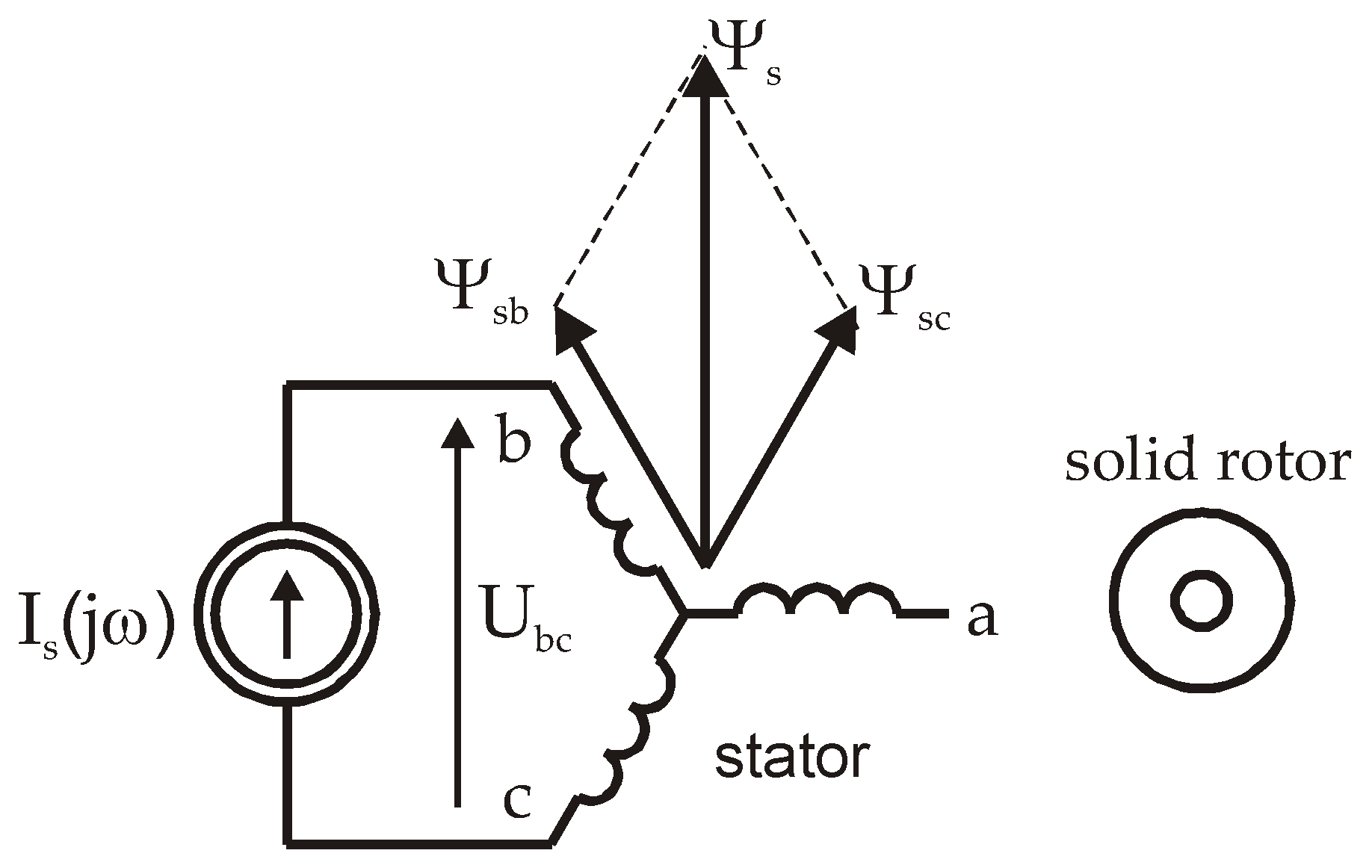
The spectral inductance was determined on the basis of the results of the calculations of the electromagnetic field distribution with the machine stationary using the finite element method. The calculations were performed in FEMM 4.2 [
33], by forcing in two phases of the stator winding connected in series (
Figure 4) a sinusoidal current with a constant value in the frequency range from 0 to 1000 Hz.
Figure 5 shows the distribution of the magnetic field in the machine cross-section, produced by the current flowing in the stator winding with a frequency of 0 Hz and 1.0 Hz.
For the frequency of 1.0 Hz, the skin effect is visible in the solid rotor.
The spectral inductance for a given current pulsation
ω is calculated from the formula [
6]
where: R
s—resistance of one stator phase, and
Zs(j
ω)—complex stator impedance, where according to
Figure 4The FEMM 4.2 program [
33] allows you to directly calculate the complex impedance
Zs for a given stator current frequency. The spectral inductance (16) of the stator should be increased by the end winding leakage inductance of the stator, because the analysis of the magnetic field in a two-dimensional system does not take into account the end winding leakage flux.
Parameters of the equivalent circuit
χ = [L
m R
k L
σk T
e α] and, thus, the approximating function (15) should be selected in such a way that the magnitude of this function |L
s(j
ω)| and its argument argL
s(j
ω) approximate the function L
s(j
ω) obtained from the analysis of the electromagnetic field with the smallest possible error. The values of the parameter vector
χ are calculated by minimizing the error of the sum of squared deviations
where: N—number of measurement points, f—stator current frequency,
Ls—spectral inductance of the winding determined on the basis of the electromagnetic field distribution using the finite element method, and L
s*—spectral inductance of the winding determined from the dependence (15) with
p = j
ω = j2πf, w
i being weight coefficients.
The Levenberg–Marquardt method implemented in the Matlab [
34] environment was used to solve the Equation (18). As a result of optimization, the following values of the sought vector
χ coefficients were obtained:
Figure 6 shows the obtained frequency characteristics of the spectral inductance L
s(jf).
To compare the magnitude and phase characteristics of the spectral inductances calculated by the finite element method and obtained as a result of the approximation by means of the fractional-order transform functions (15), the relative error defined as [
28] was used
where: Y—actual value, and Y*—value obtained on the basis of the approximating function.
The obtained relative errors for the magnitude εm = 1.5% and for the phase εφ = 2.6% prove a very good accuracy of the approximation.
4. Dynamic-State Simulation
The simulation of dynamic states was carried out for the Sg 160 M-4 squirrel-cage induction motor with rated data: PN = 11 kW, UN = 380 V (Δ), IN = 22 A, fN = 50 Hz, nN = 1460 rpm, MN = 72 Nm. In this motor, the squirrel cage rotor has been replaced by a solid rotor.
The dynamic states of an induction motor, in the rotor d, q coordinate system, are described by the following equations:
where:
ϑ—the electric angle between the stator and rotor axes of phase
a.
The differential Equations (20) and (21) result from the transformation of the differential Equation (7) and the flux Equation (8). Equation (22) is the equation of motion, while Equation (23) determines the relationship between the electric rotor speed
ω and the angle
ϑ. The stator current is determined from the relationship
Taking the dependence (23) into account, the complex voltage of the stator (12) in the rotor coordinate system will take the form
The integration of the differential Equations (20), (22) and (23) was performed using the Euler extrapolation algorithm. On the other hand, the differential Equation (21), containing the derivative of the fractional order, was solved by the Grünwald–Letnikov method [
19,
20] from the relationship
according to the algorithm implemented in the Matlab program given in [
35].
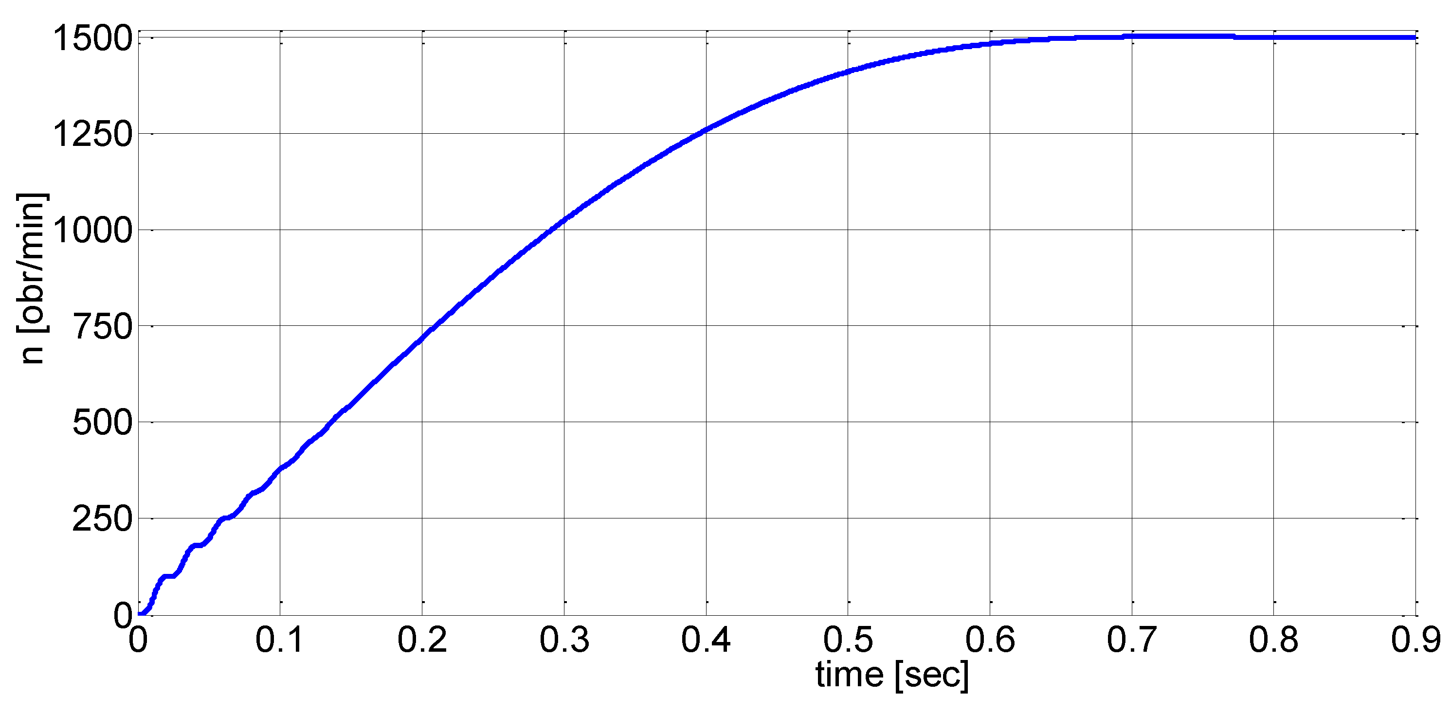
Figure 7,
Figure 8,
Figure 9 and
Figure 10 show the stator current i
s, rotational speed
n, electromagnetic torque M
e and the trajectory M
e(
n) during the start-up of a solid-rotor induction motor for the load torque M
m = 0 and the moment of inertia J = 4J
N.
On the other hand,
Figure 11 shows the torque–speed trajectory M
e(
n) during the reversion of the motor for the load torque M
m = 0 and the moment of inertia J = 20 J
N.
In
Figure 12, a flowchart of the calculation process is presented.
5. Steady State of Solid-Rotor Induction Motor
The stator voltage equation in the operator form (7) is obtained
Hence, the stator current
Applying the Laplace transform to Equation (12)
The operator form of the stator current (28) at a constant angular velocity
ω takes the form
The complex amplitude of the stator current results from the relationship (30)
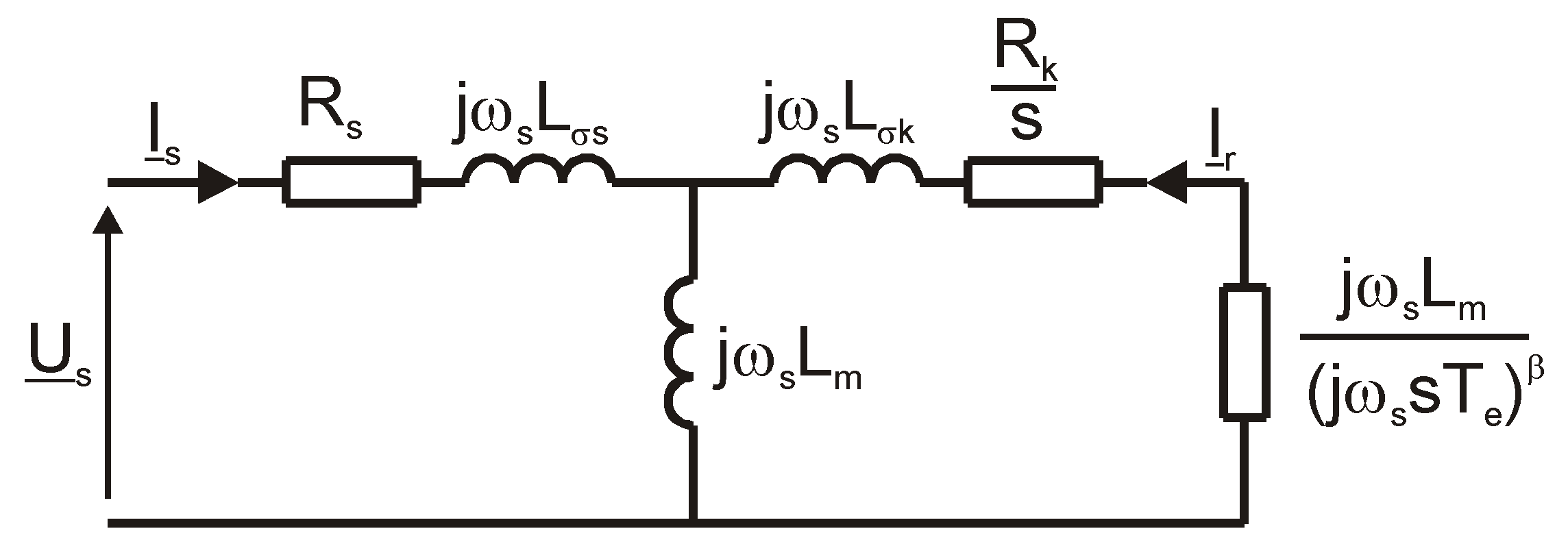
The dependence (31) shows that the equivalent circuit for the steady state is obtained on the basis of the equivalent circuit in
Figure 3 by replacing each element of this circuit with an element Z(p = j
ωss)/s (
Figure 13).
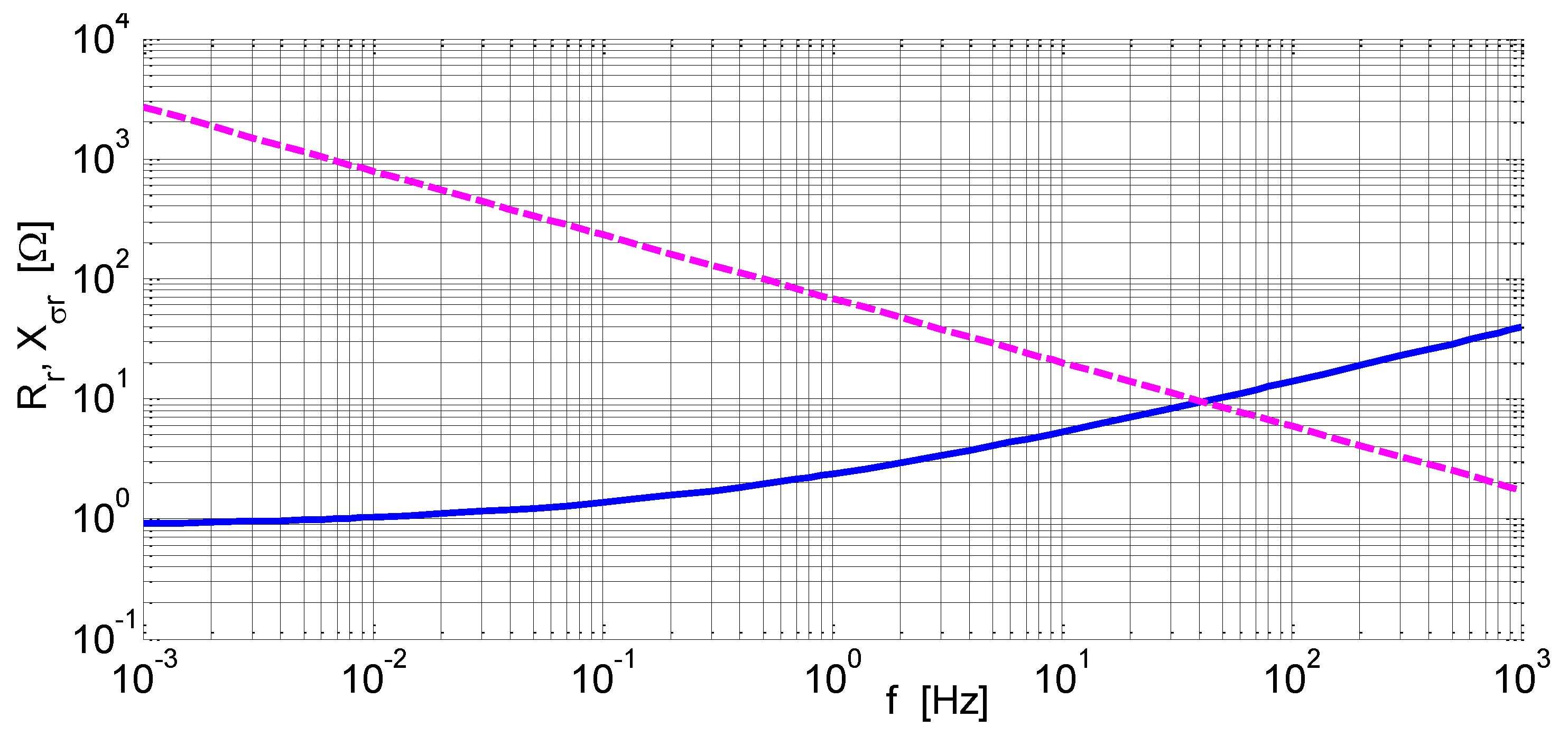
The resulting rotor impedance is given by the relationship
Hence, the resistance and reactance of a solid rotor will be, respectively:
For the coefficients
β = 0.5 and
α = 1 −
β = 0.5, the resistance and reactance of the rotor will take the form
Figure 14 shows the relationship of solid-rotor resistance and reactance on frequency.
We calculate the electromagnetic moment in the steady state from the relationship
where:
Ѱsm,
Ism—the amplitude of the flux linkage of the stator winding and the amplitude of the stator current, respectively, where
Substituting the relations (31) and (36) into the expression for the electromagnetic torque (35), we obtain
Figure 15 shows the relationship of the stator current and the rotational speed, while the dependence of the electromagnetic torque on the rotational speed is shown in
Figure 16. The calculations of the characteristics I
s = f(
n) and M
e = f(
n) were made on the basis of the spectral inductance L
s(j
ω) determined from the distribution of the magnetic field and on the basis of the equivalent circuit. On the other hand, in the case of the electromagnetic moment, the mechanical characteristic M
e = f(
n) was also determined from the steady state during the motor reversal at high engine torque.
The comparison of the characteristics presented in
Figure 15 and
Figure 16 shows a good agreement between the results calculated from the distribution of the magnetic field by the finite element method and the results obtained on the basis of the equivalent circuit, and in the case of the electromagnetic torque, with the results obtained from the transient state during the motor reversal. It proves the correct identification of the equivalent circuit parameters and the correctness of the calculation of the dynamic states of the induction motor with a solid rotor.
6. Conclusions
The transient analysis of solid-rotor induction machines can be conveniently performed in the d, q rotor reference frame (by utilizing Park’s transform) because then the rotation voltage is absent in the equivalent circuit of the rotor circuit. Therefore, the solution of differential equations containing fractional-order derivatives is simplified. The use of a fractional-order operator impedance in the equivalent circuit of the rotor, which is a series combination of resistance and inductance with constant values and the fractional-order inductance, allows for a more accurate representation of the skin effect in a solid rotor. The frequency method presented in this paper, based on the calculation of the spectral inductance by the finite element method in a large frequency range, is particularly useful for determining the parameters of higher-order models and models with fractional impedance of the rotor. This method also makes it possible to take into account the saturation of the magnetic circuit of the machine and does not require the use of an extra drive motor. However, determining the parameters by this method in an experimental way encounters significant difficulties related to carrying out measurements in the low-frequency range due to the need to use high-power voltage sources for low frequencies and the dependence of the stator winding resistance on the temperature during the measurement. For the solid-rotor induction motor model presented in this paper, the relative error of the approximation of the magnitude and phase characteristics of the spectral inductance is εm = 1.5% and εφ = 2.6%, respectively. On the basis of the equivalent diagram of the noninteger order Park, the stator voltage differential equations with integer order derivatives and the rotor voltage equations containing fractional-order derivatives were formulated. In order to simulate the dynamic states of an induction motor, an equation of motion must be added. Integration of differential equations with integer order derivatives was performed using the Euler extrapolation algorithm. On the other hand, the Grünwald–Letnikov method was used for differential equations containing derivatives of the fractional order. Integration of differential equations was carried out with a constant integration step of t = 0.1 ms. Simulation of the dynamic states of the induction motor was carried out using a program written in the Matlab environment. The simulations show that the maximum value of the electromagnetic torque during the start-up of the induction motor occurs in the second half of the first period of the torque waveform. This torque is approx. 2 times greater than the static initial starting torque of the motor in a steady state. On the other hand, the maximum value of the stator current during start-up is approx. 1.5 times the rms value of the steady-state starting current. The obtained agreement between the results calculated from the distribution of the magnetic field by the finite element method and the results obtained on the basis of the equivalent circuit proves the correct identification of the parameters and the correctness of the calculation of the dynamic states of the induction motor with a solid rotor.

