Abstract
Low salinity water injection (LSWI) is considered to be more cost-effective and has less environmental impacts over conventional chemical Enhanced Oil Recovery (EOR) methods. CO2 Water-Alternating-Gas (WAG) injection is also a leading EOR flooding process. The hybrid EOR method, CO2 low salinity (LS) WAG injection, which incorporates low salinity water into CO2 WAG injection, is potentially beneficial in terms of optimizing oil recovery and decreasing operational costs. Experimental and simulation studies reveal that CO2 LSWAG injection is influenced by CO2 solubility in brine, brine salinity and composition, rock composition, WAG parameters, and wettability. However, the mechanism for increased recovery using this hybrid method is still debatable and the conditions under which CO2 LSWAG injection is effective are still uncertain. Hence, a comprehensive review of the existing literature investigating LSWI and CO2 WAG injection, and laboratory and simulation studies of CO2 LSWAG injection is essential to understand current research progress, highlight knowledge gaps and identify future research directions. With the identified research gap, a core-scale simulation study on hysteresis effect in CO2 LSWAG injection is carried out. The results indicate different changing trend in oil recovery due to the impact of salinity on hysteresis and excluding of hysteresis effect in CO2 LSWAG injection simulation and optimization might lead to significant errors.
1. Introduction
Maximizing oil recovery from existing reservoirs plays a significant role in increasing profitability and sustainability of the oil and gas industry. Generally, oil recovery processes are classified as primary, secondary, and tertiary. In primary recovery, oil production comes from natural energy present in the reservoir. As the reservoir pressure reduces and oil production declines, secondary recovery is implemented, typically with waterflooding, to displace oil towards production wells. To achieve higher oil production, tertiary recovery, also known as enhanced oil recovery (EOR), is implemented. EOR methods such as chemical flooding (using polymers, alkaline and/or surfactants), miscible flooding (CO2, nitrogen and liquefied petroleum gases), thermal flooding (using steam), microbial flooding (microorganisms) or water-alternating-gas (WAG) injection may increase oil recovery by 5–20% of OOIP [1] depending on the specific reservoir conditions. Technical practicability of an EOR method must be coupled with an evaluation of its economic feasibility, especially during a time when the oil price is low. Moreover, as the concerns for climate change continue to increase and the petroleum industry is positioned to deal with this challenge, finding an EOR method that is both technically and economically feasible and addresses the environmental concerns is of great importance.
The chemical EOR economic evaluation conducted by Al-Murayri et al. [2] suggests that low salinity water injection (LSWI) and CO2 injection have economic potential and both of these methods have been confirmed to be effective for increasing oil recovery in both secondary and tertiary mode [3,4]. In order to achieve even higher oil recovery at low cost, a new hybrid technique was developed in the last 15 years to incorporate low salinity water (LSW) into CO2 WAG injection under both miscible and immiscible conditions [5,6,7,8]. This EOR method, termed CO2 low salinity (LS) water-alternating-gas (WAG) injection in this paper, combines the effect of LSWI with CO2 injection to enhance both macroscopic and microscopic sweep efficiency. The experimental and simulation studies [6,7,9] showed that the ultimate oil recovery using CO2 LSWAG injection was higher than using LSWI and CO2 WAG injection alone. Despite the EOR potential of CO2 LSWAG injection, some results are contradictory [10,11], where reduced oil recovery factor were reported for CO2 LSWAG injection. To the best of our knowledge, no systematic reviews were found on CO2 LSWAG injection that cover the influence of CO2 solubility in brine, salinity and composition of brine, rock composition, WAG parameters, and wettability. Therefore, a thorough review on the EOR potential of CO2 LSWAG injection will contribute to the understanding of this hybrid EOR technique and provide insights into future studies.
This literature review covers research studies related to LSWI, CO2 WAG injection and CO2 LSWAG injection. The fundamentals of CO2 WAG injection and LSWI in sandstone and carbonate are presented, including basic theory and mechanisms. Laboratory studies of CO2 LSWAG injection, including the effect of different parameters are reviewed, followed by simulation work, considering complex geochemical reactions, geological uncertainties, and optimization. Based on the laboratory studies, the proposed mechanisms and working condition of CO2 LSWAG injection are addressed along with identified research gaps. In the end, to fill the void of the hysteresis study on CO2 LSWAG injection, we have conducted core-scale simulation investigations on the impact of hysteresis under different salinities with two-phase Carlson model and three-phase Larsen and Skauge model.
2. Bibliometric Study
This literature review on CO2 LSWAG injection is defined and constrained as the following, with the goal of identifying materials focusing on CO2 WAG in injection, LSWI, and CO2 LSWAG injection. Sources are constrained to Google Scholar and OnePetro.
CO2 WAG Injection. Theory and working mechanisms.
LSWI. Mechanisms in both sandstone and carbonate are included.
CO2 LSWAG Injections. Both laboratory and simulation studies are documented. Specific considerations are given to the effect of different parameters in experimental studies and simulation studies aiming to fully capture the effect of CO2 and low salinity water.
2.1. Identification and Filtering
Searches are conducted according to the defined constraints using the listed sources. The documents which are identified as relevant are downloaded and reviewed for applicability filtering.
2.2. Discussion of Relevant Literature
Through the identification and filtering process, relevant literature has been selected and reviewed in detail. The findings are categorized based on the following hierarchy:
- CO2 WAG injection
- ❖
- Miscible and immiscible process
- ❖
- Hysteresis effect
- LSWI
- ❖
- Mechanisms in sandstone
- ❖
- Mechanisms in carbonate
- CO2 LSWAG injection
- ❖
- Experimental studies and effect of different parameters
- ○
- Miscibility
- ○
- CO2 solubility
- ○
- Brine salinity and composition
- ○
- Rock composition
- ○
- WAG parameters
- ○
- Wettability
- ○
- Pressure and temperature
- ❖
- Simulation studies
- ○
- Core scale
- ○
- Field scale
3. CO2 WAG Injection
A WAG process entails the injection of alternating cycles of gas slug and water slug at certain slug size and WAG ratio into the reservoir. As the gas is injected into the reservoir and contacts the oil, a reduction in oil viscosity is expected, which makes the oil more mobile and easier to flow. The mobility ratio (M) is generally defined as the mobility of the displacing fluid (, water/gas) divided by the mobility of the displaced fluid (, oil) [12]:
If the mobility ratio is less than or equal to 1 (), the displacement front tends to be stable, otherwise (), the further M is from 1, the less stable and favorable is the displacement. In a continuous gas injection, the mobility ratio of injected gas and oil bank, which is the gas mobility divided by oil mobility, is generally very unfavorable. Thus, a technique to overcome this problem was developed, in which slugs of water and gas are injected alternately. The injection of water decreases the mobility ratio compared to the injection of gas alone; hence, mobility ratio in the process is improved. Gravity segregation induced by the density differences between the gas and fluid phase is another important mechanism. Due to gravity forces, waterflooding is more likely to sweep the lower part of a reservoir and injection of gas sweeps more of the upper parts. Holm and Josendal [13] and Perera et al. [14] listed the characteristics which enables CO2 to remove oil from the reservoir effectively (Figure 1), including the effect of CO2 physical and chemical characteristics on oil phase, brine phase and reservoir rock. CO2 promotes oil swelling and viscosity decrease. The formation of carbonic acid (H2CO3) could lead to dissolution of carbonate, which further increases porosity and permeability near the injection zone [15]. This acidic effect also contributes to the stabilization of negatively charged clay particles [16].
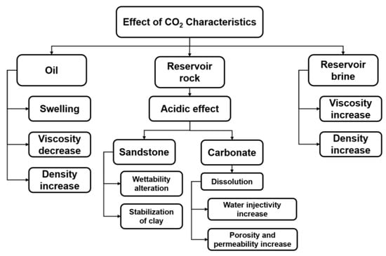
Figure 1.
Effect of CO2 physical and chemical characteristics on oil/brine/rock.
Generally, during a CO2 WAG injection process, utilization of CO2 can achieve enhanced oil recovery through either miscible or immiscible process. The development of miscibility between injected CO2 and reservoir oil is dependent on several factors, such as the pressure and temperature of the reservoir, and properties of reservoir oil, including API gravity, molecular weight, and composition of oil (i.e., concentration of intermediate components, or C7+ fraction) [17].
3.1. Miscible Process
In the oil recovery process of gas injection, the injected gas will develop first contact or multiple contact miscibility with the oil [14]. First contact refers to the process that the injection of the solvent forms a single phase upon first contact that is miscible with the crude oil and, typical for recovering light oil using liquified petroleum gases (LPG). The latter process achieves miscibility with different contacts as the fluids move through the reservoir by vaporizing and condensing gas drive, typical for solvents like CO2 [18].
Among the factors that affect CO2 miscibility in oil, pressure of the reservoir is the most important and a key parameter for determining miscibility [19,20]. Generally, miscibility between CO2 and reservoir oil is achieved with pressure above the minimum miscible pressure (MMP). The CO2 miscible process is illustrated in Figure 2, showing a transition zone, miscible with the forefront reservoir oil and the injected pure CO2 near injection well. Jarrell et al. [21] demonstrate a development of transition zone with no interface by the mass transfer between reservoir oil and CO2. Two processes are considered as the miscibility development of CO2 with reservoir oil: (1) condensing gas drive; and (2) vaporizing gas drive. In the former process, the injected CO2 dissolves into the reservoir oil, forming dynamic miscibility. In the latter process, reservoir oil component with intermediate-to-high molecular weight vaporizes into CO2, and form miscibility under certain conditions.
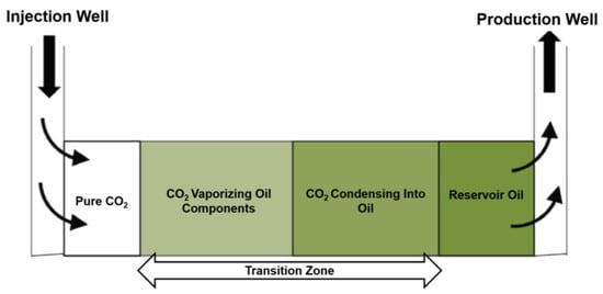
Figure 2.
Schematic CO2 miscible process (adapted from Verma [18]).
3.2. Immiscible Process
CO2 is unlikely to develop miscibility if the reservoir pressure is below the MMP or the composition of reservoir oil is unfavorable (i.e., heavy oil) [18]. Under these circumstances, CO2 and oil will not form a single phase. With immiscible CO2 WAG injection, improved oil recovery is achieved by oil swelling and viscosity reduction induced by dissolution of CO2 into reservoir oil. Thus, CO2 solubility in the reservoir oil is a key factor for effective implementation of immiscible CO2 WAG injection. CO2 solubility in oil can be affected by saturation pressure, temperature of the reservoir, and composition of oil [22,23]. As pressure increases or temperature decreases, CO2 solubility in oil increases. However, as the temperature is lower than CO2 critical temperature, CO2 solubility is also affected by oil composition and liquefaction, where gaseous CO2 is more soluble in crude oil than liquid CO2 [24,25,26]. Commonly recognized oil recovery mechanisms for the immiscible CO2 displacement process include oil swelling and viscosity reduction [27,28,29,30], IFT reduction [31,32], and blowdown [13,31,33].
3.3. Hysteresis
During CO2 WAG injection process, changes in saturation of water and CO2 are expected after each injection cycle in a multiphase flow. Due to the alternating injection cycles of water and gas, saturation of water and gas will increase and decrease alternately, which generates a hysteresis loop. This hysteresis phenomena can be seen in both capillary pressure and relative permeability, represented by drainage and imbibition processes. The cyclic WAG process could induce favorable hysteresis relative permeability effect which assists in reducing the mobility of gas to achieve superior conformance control and higher ultimate sweep efficiency [34]. Generally, the three-phase hysteresis effect is more pronounced in immiscible WAG process than miscible WAG process [35] and its impact is more significant with non-wetting phase (gas) than wetting or intermediate wetting phase [36].
4. Low Salinity Water Injection (LSWI)
Low salinity effect (LSE) was first discovered by Bernard [37] in 1967 when he observed that oil recovery in formations containing hydratable clays increased as the concentration of the injected sodium chloride brine was decreased from 1% to 0.1%. Subsequently, researchers and companies worldwide have studied LSE and confirmed that injection brine composition and salinity can have an enormous impact on oil recovery [38,39,40,41,42,43,44,45,46,47,48,49,50,51,52,53,54].
4.1. Proposed Mechanism of LSWI in Sandstone
Even though numerous works has been conducted to investigate the underlying mechanism of LSWI, there is no consistent explanation and LSE might be a result of several proposed mechanisms acting together. One reason is because of the complex compositions or structures of the aqueous phase, oil phase and rock minerals. Another reason is the complex geochemical interactions between/among all these phases [55]. Figure 3 summarizes some of the proposed LSWI mechanisms and their related effects in sandstone. These mechanisms were postulated from either direct pore-scale and nano-scale observations or indirect measurements such as pH and ion concentration measurements from core scale and field scale.
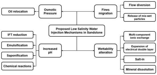
Figure 3.
Overview of some proposed mechanisms of LSWI in sandstones.
Fines migration can be induced by the poorly cemented clay minerals [56] or release of mix-wet particles [41]. These released fines will migrate with fluid flow to zones with higher permeability and lodge in smaller pores or pore throats, resulting in diversion of the flow path to unswept zones with lower permeability. Hence, sweep efficiency is improved [41,57]. In situ increase in alkalinity [58] arising from the differences in cation affinity to negatively charged surface [59] gives rise to IFT reduction, surfactant-like behavior and chemical reactions for oil detachment [58,60]. Osmotic effect is generated by the difference in chemical potential of a system containing low and high salinity solutions with a semipermeable membrane in between. This difference acts as a driving force for the movement of water and oil relocation [61,62,63,64,65]. Additional oil recovery by LSWI is often observed with wettability alteration towards more water-wet [50,66,67,68,69]. The proposed mechanisms related wettability alteration are multi-component ionic exchange (MIE) [70,71], expansion of electrical double layer [47,72,73], salt-in effect [53], and mineral dissolution [74]. For a detailed review and discussion on the mechanisms, readers can refer to the work conducted by Sheng [3], Rezaeidoust et al. [53], Katende and Sagala [75], Al-Shalabi and Sepehrnoori [76], and Yue et al. [77].
4.2. Proposed Mechanism of LSWI in Carbonate
In carbonate reservoirs worldwide, less than 30% of oil has been recovered due to low permeability, natural fractures, inhomogeneous rock properties and more than 80% of the carbonate reservoirs are intermediate or oil-wet [78,79]. Compared to the complexities of LSE in sandstone, the most acceptable working mechanism of LSWI in carbonate is the wettability alteration from oil-wet to intermediate or water-wet due to changes in rock surface charge and microscopic dissolution of anhydrite (Figure 4) [76,80,81,82].
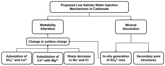
Figure 4.
Summary of proposed mechanisms of low salinity water injection in carbonates.
Changes in rock surface charge. Ca2+, Mg2+ and SO42− are the determining ions for wettability alteration in carbonate reservoir. For seawater injection in chalk, the adsorption of SO42− to the chalk surface lowers the positive charge on rock surface and electrical repulsion; thus, more Ca2+ will be attached to the chalk surface and react with the carboxylic group, promoting the detachment of the organic carboxylic materials [83,84,85]. At higher temperature, the reactions between the ions and rock surface become more pronounced, making Mg2+ capable of substituting Ca2+ on the rock surface, [86,87], leading to more detachment of oil. Subsequently, Yousef et al. confirmed LSE in carbonate as a result of wettability alteration and the effect of IFT reduction is negligible [88,89]. Low salinity water with a significant reduction in the concentrations of Na+ and Cl− is the key to trigger wettability alteration in carbonate reservoirs [54,82,88].
Mineral dissolution. Mineral dissolution during flooding could result in secondary pore structure and potentially expelling of oil [76]. Additionally, the microscopic dissolution of anhydrite occurring during injection of low salinity water leads to in situ generation of SO42− which promotes wettability alteration [82,90].
5. CO2 LSWAG Injection
Based on the review on LSWI and CO2 WAG injection, it is possible to combine the strength of these two methods to alter wettability and enhance CO2 mobility; thus, increasing oil displacement efficiency. A comprehensive review of CO2 LSWAG laboratory and simulation studies has been completed; it is presented accordingly with proposed mechanisms and environmental aspects of CO2.
5.1. Laboratory Observations of CO2 LSWAG Injection
Over the past 15 years, core flooding experiments have been carried out to investigate CO2 LSWAG injection in both sandstone and carbonate. The EOR potential of CO2 LSWAG injection is shown in light-to-heavy crude oil. Table 1 summarizes the experimental data from literature.

Table 1.
Summary of CO2 Low Salinity WAG Injection Laboratory Experiments.
Most results confirmed improved oil recovery using this hybrid technique, in both secondary and tertiary modes, with some exceptions [10,11]. Studies with negative or neutral outcomes used core samples that were either not aged or aged for just three days, which would lead to a strongly water-wet initial wettability. This initial condition is not favorable for low salinity water to be effective [66,67]. Moreover, the salinity of injection water adopted in the core flooding experiments by Jiang et al. [11] is 10,000 ppm, which lies beyond the range suggested for LSWI (1000–5000 ppm) [58]. It can be seen that the success of a CO2 LSWAG process is dependent on a variety of parameters, hence, the effects of injection brine composition and salinity, rock composition, miscibility, WAG parameters, solubility of CO2 in brine, and wettability alteration on oil recovery enhancement are reviewed and discussed in this section.
5.1.1. Effect of Miscibility
Based on a WAG injection field review by Christensen et al. [100], higher oil recovery is generally achieved by miscible or near-miscible WAG injection in comparison with the immiscible process. However, the investigation of the importance of miscibility on gas flooding conducted by Thomas et al. [101] suggests that miscibility might not be necessary for increasing oil recovery as long as the IFT has been reduced to a desired level, which is identified as the level to effectively enhancing oil recovery. It is noteworthy that this conclusion is dependent on the interplay between mobility and IFT, which determines the success of a WAG process [4,101]. Up to date, only one study was found on the investigation of miscibility effect during CO2 LS and HS WAG injection. Kulkarni et al. [102] conducted core flooding experiments on Berea sandstone. The oil phase used is n-decane and the aqueous phase are two brines (5% NaCl and Yates reservoir brine). Pure CO2 is used as the injection gas under miscible and immiscible conditions. Their results, shown in Table 2, indicate that miscible CO2 WAG injection yields higher oil recovery than the immiscible process. However, it is worth noting that the oil phase used in this study is n-decane, which is non-polar. Therefore, the difference between miscible and immiscible displacement could be mainly ascribed to the effect of CO2 miscibility with oil, and LSW might not play a role for improving oil recovery [103].

Table 2.
Oil recovery comparison between miscible and immiscible WAG injection [102].
5.1.2. Effect of CO2 Solubility in Brine
Previous experimental and modeling studies demonstrate that CO2 solubility in brine increases with decreases in salinity [9,104,105,106]. This increment of CO2 solubility with low salinity water can result in improved oil recovery through CO2-brine IFT reduction [9]. Bennion and Bach [107] conducted regression analysis on the correlation of IFT of CO2 and brine with reservoir pressure, temperature, and CO2 solubility. Their results showed that the IFT of CO2 and brine decreases with increasing CO2 solubility in brine. Yang et al. [108] used the axisymmetric drop shape analysis technique to obtain the IFT of the crude oil, reservoir brine, and CO2 systems at 27 and 58 °C and pressures up to 31 MPa. They found that reduced as CO2 was introduced to the system. Moreover, the reduction in and was observed with increasing pressure or increasing CO2 solubility. Thus, with the injection of LSW and CO2, solubility of CO2 in LSW is higher, which might promote enhancement of oil recovery by reduction in IFT. From the study performed by Zolfaghari et al. [7], a 5% increase in oil recovery was observed using CO2 LSWAG injection compared to LSWI alone at the same pore volume of injection, indicating the low pH buffer solution developed by the dissolution of CO2 in LSW has positive impact on oil recovery. The reduction in with increasing CO2 solubility may contribute to the enhancement of oil recovery in this case.
Chaturvedi et al. [8] investigated the impact of salinity (1–4 wt% NaCl brine) on CO2 absorption under 4, 8 and 12 bar confining pressures at 50 and 80 °C. The dominant absorption of polar gas CO2 is physisorption, where CO2 is trapped in the form of bubbles and encapsulated by layers of water [8]. A small part of the gas molecules reacts with water, and the following reactions will take place to produce carbonic acid () and and ion.
The CO2 molality, moles of CO2 absorbed in a solvent, as a function of salinity is depicted in Figure 5, showing that CO2 absorption decreases with increasing salinity and temperature, and decreasing pressure.
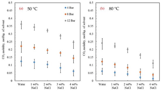
Figure 5.
CO2 molality results for different salinities (0–4 wt% NaCl); (a) 50 °C; (b) 80 °C [8].
They used the Young-Laplace equation of capillarity to calculate the IFT between CO2 and brine [109]. As shown in Figure 6, the interfacial tension of brine and CO2 decreases with decreasing salinity and increasing temperature and pressure. Chaturvedi et al. [8] claimed that the decrease in IFT is ascribed to the increasing CO2 solubility in water with increasing pressure and decreasing salinity at the same temperature and pressure, with one exception of the IFT measured at 80 °C, 12 bar and with 2 wt% NaCl. The conducted CO2 LS WAG core flooding experiments recommended the use of low salinity water (1 and 2 wt% NaCl) in conjunction with CO2 injection to improve oil recovery [8].
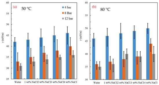
Figure 6.
CO2− brine solution interfacial tension at different pressures (4–12 bar) and temperature of (a) 50 °C; (b) 80 °C [8].
5.1.3. Effect of Brine Composition and Salinity
The salinity of injection brine is an influential parameter in the oil recovery process, as confirmed by several numerical and experimental investigations [40,42,110,111]. Jiang et al. [11] conducted CO2 LS and HS WAG core flooding experiments with model oil (n-decane and n-hexadecane) and reservoir oil. The Berea sandstone core samples were aged for three days at reservoir temperature (60 °C). Alternating cycles of CO2 and brine with slug size of 0.5 PV and WAG ratio of 1:1 were applied in every core flooding test. In the CO2 HS WAG flooding experiments with model oil, 1000 ppm NaCl was used as formation brine. The salinities of injection NaCl brine were 1000, 2000, 4000, 8000, 16,000, and 32,000 mg/L. The effect of divalent cations was investigated by comparing the oil recovery factor with injection brine with 8000 ppm NaCl and 4000 ppm NaCl + 4000 ppm CaCl2. Their results show that the recovery factor of the tertiary mode increases slightly with elevated injection brine salinity, with no signs of ionic exchange. It is suggested that the decrease of CO2 solubility in high salinity brine is responsible for the higher oil recovery. They also found that the effect of divalent cations Ca2+ in the injection brine is similar to that of Na+ based on the comparison between the oil recoveries with injection of 8000 ppm NaCl or 4000 ppm NaCl + 4000 ppm CaCl2. However, it is worth pointing out one of the drawbacks of the experimental design that the oil used is non-polar, therefore, the ligand bonding or cation exchange suggested by Lager et al. [70] for LSE to occur might not be able to take place. Therefore, the conclusion that effect of Ca2+ and Na+ is similar is not generalized. In their LS and HS WAG injection experiments with crude oil, 20,000 ppm NaCl + 10,000 ppm CaCl2 is used as formation brine. The salinities for injection brines are 10,000, 16,000 and 32,000 ppm, a combination of 66.67% NaCl and 33.33% CaCl2. The recovery factors of WAG injection as tertiary mode increase slight with salinity, from 38% to 40%, however, the overall recovery factor decreases with salinity. From their experiments, the effectiveness of CO2 LSWAG injection is certainly dependent on several factors, such as composition of oil and brine. However, we cannot simply draw a conclusion that CO2 HSWAG injection is more effective in terms of EOR since the LSW used in the water cycle is not within the salinity range recommended [58].
On the other hand, Zolfaghari et al. [7] obtained different results with similar core flooding experiments on kaolinite-free core samples. The samples were aged for two days in heavy oil (with 6.5% asphaltene content) at 70 °C before flooding. Synthetic brine concentrations of 1000 ppm (20% CaCl2 + 80% NaCl) and 50,000 ppm (20% CaCl2 + 80% NaCl) were used. Five WAG cycles with 0.16 PV slug size and WAG ratio of 1:1 were applied for each CO2 LSWAG injection (secondary mode). The LSE was observed in all experiments despite the fact that the core samples are free of kaolinite and only aged for two days. The authors ascribed the observed EOR effect to CO2 and its buffer effect in the presence of water. They argue that this buffer effect induced by CO2 casts doubt on the mechanism proposed by McGuire et al. [60], that LSWI is like alkaline flooding. This positive influence of low salinity water in heavy oil indicates that the application of CO2 LSWAG injection may not be limited to light-to-medium oil reservoirs.
AlQuraish et al. [96] investigated CO2 low salinity (LS) and high salinity (HS) WAG injection as tertiary recovery to explore the effect of salinity and brine composition. In their study, synthetic formation water at 20 wt% salinity, seawater (acting as high salinity water, HSW), and 10-time diluted seawater (acting as low salinity water, LSW) were used as the aqueous phase. Detailed information of the brine compositions can be found in Table 3. The oil phase was light crude oil. They conducted LSW and HSW flooding as secondary recovery, followed by miscible CO2 LS and HS WAG injection. The results show that incorporating LSW into miscible CO2 WAG injection is effective in providing 18.7% higher incremental oil recovery compared with the use of HSW in Berea sandstone.

Table 3.
Composition of brine [96].
The depletion of monovalent ions and dilution of multivalent ions during injection of modified seawater (detailed composition can be found in Table 4) was studied by Al-Saedi et al. [95]. Their results (Table 5) (1 formation brine; 2 seawater; 3 modified seawater; 4 without NaCl; 5 without NaCl and 5-time diluted Ca2+; 6 without NaCl and 5-time diluted Mg2+; 7 without NaCl and 5-time diluted SO42−.) showed that injection brine without NaCl resulted in 10% more oil recovery than seawater flooding. They also found that diluting the Ca2+ concentration fives and depleting NaCl in the injection brine could increase 19.25% oil recovery and if it is injected alternatively with CO2, further enhancement in oil recovery could be expected. It is suggested that dilution of Ca2+ ions assist in improving oil recovery by shifting the following reaction towards the right direction [98], resulting in more desorption of oil from the negatively charged surfaces.

Table 4.
Composition of the formation and injected brine [95] (mg/L).

Table 5.
Recovery factor of different flooding sequences [95].
Even though these modifications are conducted on seawater, these results suggest that it might be possible to achieve higher oil recovery in CO2 LSWAG injection with the manipulation of ion compositions and WAG process is more efficient compared to modified seawater and continuous CO2 injection. It can be inferred that further dilution of Ca2+ or depleting Ca2+ in LSW might improve oil recovery even more when injected alternatively with CO2.
Al-Abri et al. [97] studied the performance of immiscible CO2 LSWAG injection in sandstone cores with different brine compositions; 5000 ppm NaCl, 5000 ppm KCl and 5000 ppm MgCl2 as three different injection brines. Their results show that injection of NaCl brine yields the highest oil recovery, followed by MgCl2 and KCl brine. CO2 solubility is found to be lowest in 5000 ppm NaCl and highest in 5000 ppm KCl. Even though the authors suggest that MIE mechanism of Na+ replacing the divalent cations, less CO2 solubility in NaCl LSW could also be one cause.
5.1.4. Effect of Rock Composition
AlQuraish et al. [96] performed miscible CO2 LSWAG injection in Berea and Bentheimer sandstones to investigate the effect of rock composition. Both samples were primarily composed of quartz with kaolinite clay, 2% kaolinite for Berea and 0.5% kaolinite for Bentheimer. CO2 LSWAG injection outperformed CO2 HS (high salinity) WAG injection in the Berea core samples in terms of oil recovery, whereas CO2 HS WAG injection results in higher oil recovery in the Bentheimer core samples (Table 6). This observation indicates that the presence of clay minerals, especially kaolinite, might be essential for CO2 LSWAG injection to be effective. The experiments of LSWI conducted at core scale [41] and pore scale [57] suggested that the migration of fine particles (especially kaolinite) might be a contributor to improved oil recovery in sandstones.

Table 6.
Comparison of total recovery for Berea and Bentheimer core samples [96].
Zolfaghari et al. [7] cast doubt on considering kaolinite migration as a key mechanism in LSWI since the core samples they used in their experiments are free of kaolinite, and additional oil recovery is observed. In a pore-scale visualization of LSWI performed by Amirian et al. [112], fines migration was reported to play an insignificant role. Further investigations are required to better understand the roles of clays in CO2 LSWAG injection.
5.1.5. Effect of WAG Parameters
Generally, WAG parameters include WAG ratio, slug size and WAG cycle. It is necessary to regulate the slug size of injected water and gas and determine the optimum WAG ratio and cycle to achieve the best displacement efficiency. Selecting of unfavorable parameters in a WAG process would possibly lead to low oil recovery. Therefore, it is essential to conduct optimization and sensitivity studies before initiating a WAG process.
Le Van et al. [94] investigated the effect of slug size (0.2, 0.4, 0.6 PV) and salinity (1000, 2000, 3000, 4000 and 5000 ppm NaCl) on CO2 LSWAG injection using core flooding experiments and response surface methodology (RSM) to optimize the variables. Their results indicate that the optimal oil recovery by RSM was achieved with 0.455 PV of slug size and 4313 ppm NaCl injection brine. However, this optimization of CO2 LSWAG injection is a simple approach and cannot be generalized. Dang et al. [6] conducted robust optimization on CO2 LSWAG injection under geological uncertainties [113] considering WAG parameters, brine composition, injection pattern location and bottom hole pressure (BHP) of production wells. Net present value (NPV) is the objective function and realizations are generated with varying distribution of facies and clay content. DECE (Designed Exploration Controlled Evolution) optimization method [114,115] is employed for finding the optimal results. WAG ratio is found to have significant effect on ultimate oil recovery and the highest is achieved with WAG ratio of 1:2. They claim that due to the higher CO2 solubility in LSW, make-up of CO2 is needed to achieve higher oil recovery. Therefore, WAG ratio of 1:2 is found to be optimum in their study. Zekri et al. [93] conducted miscible CO2 HS and LS WAG injection in carbonate cores using different WAG ratios (1:1, 2:1, and 1:2). The comparison among these cases in terms of oil recovery is shown in Figure 7. WAG ratio 1:2 yields the highest oil recovery and WAG ratio of 2:1 results in the lowest irrespective of salinity difference. LSE is hindered while employing WAG ratio of 1:1 and the best synergy of LSW and CO2 is achieved with WAG ratio of 1:2. Therefore, a WAG ratio of 1:2 is considered as the optimum in their case. This finding is in accordance with the optimization conducted by Dang et al. [6].
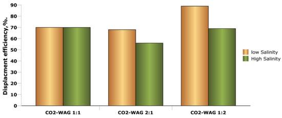
Figure 7.
Effect of WAG ratios on oil recovery in CO2 HS and LS WAG injection [93].
Since limited studies on CO2 LSWAG optimization or effect of WAG parameters are found from literature so far, thus, it would be beneficial to refer to other WAG injection optimization work for identifying potential research topic. Chen et al. [116] performed miscible CO2 WAG optimization using stochastic algorism GA (genetic algorithm) to locate optimum solution of WAG ratio and cycle, injection rates and BHP of producer. Their results suggest an optimum WAG ratio of 1:2 and the sensitivity study show that finding an optimal gas slug size assists in maximizing oil recovery. Mohagheghian et al. [117] used GA and PSO (particle swarm optimization) for optimization and sensitivity studies, showing that WAG ratio of 0.15 for maximized oil recovery and 0.9 for maximized NPV. To overcome the time-consuming drawback of conventional optimization methods which are as function of time, light mathematical Proxy models are developed for WAG parameter optimization, which outputs NPV or oil recovery at a given time [118]. They found that a WAG ratio of 2.85 results in highest oil recovery in their case. These results differ from the optimum ratio of 1:1 reported from laboratory experiments [119,120,121] and most field applications [4,100] for WAG injection (without incorporating LSW). This could be caused by neglecting affecting factors such as reservoir heterogeneity or gravity forces. Additionally, with the incorporation of LSW into CO2 WAG injection, the difference of CO2 solubility in HSW and LSW would potentially lead to employing WAG ratio lower than 1, indicating that larger injection volume of gas could contribute to EOR of CO2 LSWAG injection. However, whether lowering WAG ratio to less than 1 is optimum in increasing oil recovery requires more laboratory experiments on CO2 LSWAG injection.
5.1.6. Effect of Wettability
According to Anderson [122], wettability is the main factor which governs the fluids distribution, the flow path and the location. Generally, the wetting state of a rock surface is affected by salinity, mineralogy of the rock, crude oil content, temperature and pressure, pH of formation and injected brine, and gas in solution. Teklu et al. [9] performed contact angle measurements between reservoir sandstone core discs to mimic a condition of miscible CO2 flooding with seawater and low salinity water (Figure 8). The measurement condition A, B, and C are described in Table 7.

Figure 8.
Contact angle between sandstone and oil-droplet at conditions A, B, and C [9].

Table 7.
Measurement condition A, B and C [9].
As brine salinity decreases, the solubility of CO2 increases, forming in situ carbonated water of higher CO2 saturation in the brine phase. This leads to IFT reduction and wettability alteration of rock towards hydrophilic; hence, improved oil recovery [9]. Similar results were observed from Almeida da Costa et al. [123]. They performed contact angle and IFT measurements in the crude-oil/CO2/water/rock system at 725 psi and 2610 psi, and 60 °C. As shown in Figure 9, the IFT between crude oil and CO2 decreases with increasing pressure, indicating enhanced molecular interactions, and also contributes to increased oil mobility [123]. The observation of a reduction in water contact angle as pressure increases indicates that the rock surface becomes more water-wet while CO2 migrates towards the oil-water interfaces, resulting in the swelling of the oil drop over time.
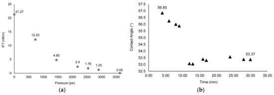
Figure 9.
(a) IFT of crude oil/CO2; (b) Contact angle as a function of time and pressure in a low salinity brine/CO2 system at 60 °C (adapted from Almeida da Costa et al. [123]).
Al-Abri et al. [97] investigated the wettability alteration by CO2 LS WAG injection based on the calculated wettability index (WI) from contact angle measurements. The definition of WI is defined as
where, is the contact angle obtained after samples have been aged in base brine, is the contact angle obtained after samples have been aged in crude oil, and is the contact angle obtained after samples have been aged in brine with different salinities. Their results are shown in Table 8. A WI greater than one means more water-wet compared to the initial condition. The experimental results demonstrate that a favorable wettability alteration is achieved by NaCl and KCl brine compared to MgCl2 brine (see Table 8, samples 3, 5 and 7). Moreover, as CO2 is incorporated into low salinity water, the wettability index increased and the final contact angle decreased (Table 8), indicating the alteration of wettability towards more water-wet. They also conducted three tertiary CO2 LS WAG core flooding experiments with high salinity flooding as secondary recovery. The lowest oil recovery (43.5%) was obtained in the combined injection of CO2 and KCl brine, which has the lowest wettability index. This suggests that the wettability alteration by the interactions between LSW, CO2 and rock minerals could be one of the contributors to improved oil recovery.

Table 8.
Value of contact angle and wettability index [97,123].
Data from wettability studies of CO2-enriched brine, sandstone and crude oil is very limited. In all cases, CO2 and brine typically exist as a single phase, forming in situ carbonated water. The study of salinity effect on contact angle in the CO2/brine/oil system by Ameri et al. [124] showed that wettability of the substrate was altered from strongly water-wet to a less water-wet state with decreasing salinity (Figure 10). Their results disagree with that of Teklu et al. [9], who found that the contact angle increases with increasing salinity. This could be due to the effect of exposure time of CO2 enriched brine on the oil saturated sandstone substrate. The study conducted by Seyyedi et al. [125] found that the values of the contact angle measured in the system with CO2-enriched brine were slightly higher than those measured in the system with brine phase alone, which indicates that injection of CO2 alters the wettability towards slightly less water-wet in quartz rock. This finding is also contradictory to the results from Teklu et al. [9] and Al-Abri et al. [97]. The difference in the findings can be ascribed to the salinity of the brine and the rock minerals used in the experiments. Therefore, it is necessary to conduct more investigations on the effect of interactions among crude oil, sandstone or pure quartz, salinity of brine, and CO2 on wettability alteration during CO2 LSWAG process.
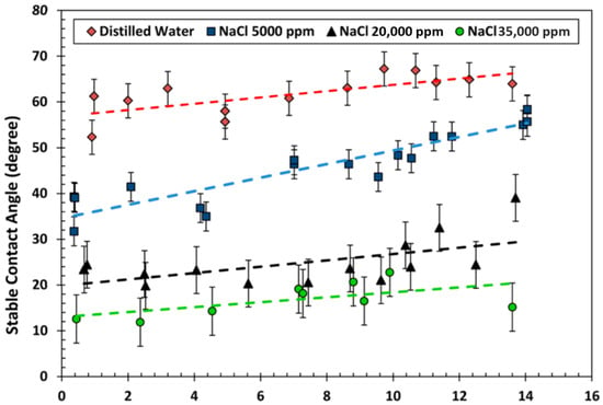
Figure 10.
Contact angle measurements for sandstone after being saturated with oil, brine and CO2 at 45 °C [124].
It is seen that injection of CO2 and LSW could potentially result in wettability alteration, which affects ultimate oil recovery. Additionally, initial wettability of the reservoir is also an affecting factor not only for the effectiveness of LSWI, but also for hysteresis effect during LSWAG cycles. Even though no studies have conducted so far to investigate the effect of initial wettability on hysteresis effect of CO2 LSWAG injection, Shahverdi et al. [126] have performed investigation on relative permeability and hysteresis during WAG injection in reservoir rock with different initial wettability. Their results report that no considerable hysteresis in relative permeability was observed for water-wet cores, whereas the intermediate cores show slight cyclic hysteresis. Injection of LSW into reservoir rock that is initially intermediate-wet to oil-wet, wettability alteration could occur. When LSW is incorporated with CO2 WAG injection, it is possible that it could have an impact on hysteresis, which requires more investigation.
5.1.7. Effect of Pressure and Temperature
During a CO2 LSWAG injection, pressure determines whether CO2 remains miscible or immiscible with the reservoir oil [19,20]. For a certain reservoir, as discussed in Section 5.1.1, with pressure higher than MMP, higher oil recovery is expected compared to the scenario with low pressure which is below MMP. Pressure and temperature could also affect the solubility of CO2 in oil and water and the interfacial tension of CO2-brine, CO2-oil, and oil-brine [8,123]. These effects have been discussed in Section 5.1.2 and Section 5.1.6. However, investigations on the overall effect of pressure and temperature on CO2 LSWAG injection are very limited.
Chaturvedi et al. [8] investigated increased oil recovery due to CO2 LSWAG injection in sand-packs at temperature of 323 K and 353 K (Figure 11). The salinities of the injected NaCl brine are from 0 to 4 wt% NaCl. It is seen that with 0–1 wt% NaCl injection brine, oil recovery increases with injection temperature. However, with 2–5 wt% NaCl injection brine, oil recovery decreases with increasing temperature, from 323 K to 353 K.
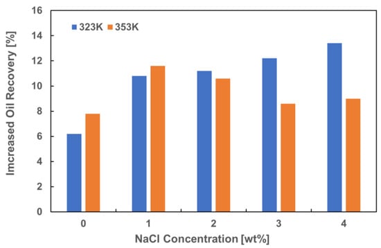
Figure 11.
Oil recovery of core flooding experiments in sand-packs with CO2 LSWAG injection at test temperature of 323 K and 353 K (adapted from Chaturvedi et al. [8]).
5.2. Simulation Studies of CO2 LSWAG Injection
Extensive modeling works have been carried out on the WAG process. The effect of different parameters, such as WAG ratio, cycle volume, wettability [127,128,129,130], relative permeability, capillary pressure [35,36,128,130,131,132,133,134], petrophysical properties [130,135,136], and miscibility [35,36,130,133,137,138], have been investigated. However, only a few modeling [134,139,140,141,142] studies have been conducted on LSWI, mainly due to the complex geochemical reactions in the crude-oil/brine/rock (COBR) system and lack of consensus on some of the proposed LSWI mechanisms. Generally, the dominant mechanism considered for modeling LSWI is wettability alteration achieved by interpolation between two relative permeability curves, representing high and low salinity water. The interpolants can be salinity [134], salinity of a specific aqueous component [143], equivalent fraction of a specific aqueous component on the exchanger [140,141,142,144], or porosity changes induced by mineral dissolution. Fjelde et al. [139] used a 1-dimensional fully implicit black oil simulator for history matching of the water-oil relative permeability and capillary pressure curves. The curves for relative permeability and capillary pressure are estimated based on the production history and differential pressure. In order to achieve a relatively accurate model for LSWI, the two sets of relative permeability curves need to be precisely defined and geochemical reactions like intra-aqueous reactions, ionic exchange, and mineral dissolution/precipitation should be incorporated into the simulator.
Preliminary modeling of the CO2 LSWAG hybrid process was initiated by Dang et al. [6] and followed by Naderi and Simioo [111] and Nguyen et al. [145]. Dang et al. [6] first performed simulations in a 1-dimensional heterogeneous reservoir and then upscaled to a field scale. They used the model from Nghiem et al. [146] to simulate the CO2 flooding process considering CO2 dissolution in oil and water, and models from Dang et al. [142,144] to simulate LSWI process taking into account of ion exchange, mineral dissolution, and wettability alteration. These proposed models have been implemented in an equation-of-state compositional simulator. Ion exchange and wettability alteration are considered to be the dominant mechanism of LSWI [6]. Wettability alteration by LSWI is modeled with relative permeability curves shifting towards more water-wet. Their results [6] confirmed the advantages of CO2 LSWAG injection. Calcite dissolution was found to play an important role since higher oil recovery is observed with an increase in the amount of calcite. Subsequently, they extended the simulation to the field scale implementation of CO2 LSWAG injection in the Brugge field reservoir through an integrated workflow including geological modeling, multi-phase and multi-component reservoir flow modeling, and robust optimization. One interesting observation from their results is that LSWI could potentially compensate for the delayed production caused by CO2 injection (Figure 12). We consider the acceleration of oil production in the early stage is due to the effect of LSW, which promotes the ion exchange and other geochemical reactions, favorable for oil production. Naderi and Simjoo [111] adopted similar approach for modeling and investigating EOR potential of CO2 LSWAG injection in oil-wet sandstone. Their results support the potential application of CO2 LSWAG injection and the rate of calcite dissolution increased due to the dissolution of CO2 into the water phase, which further promotes geochemical reactions of the rock/oil/brine/CO2 system.
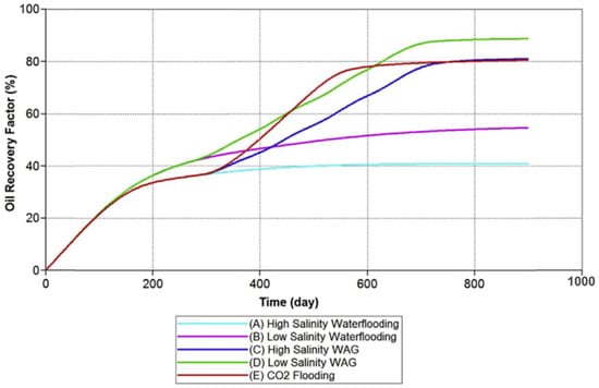
Figure 12.
Cumulative oil recovery of different cases [6].
Subsequently, Nguyen et al. [145] modeled fines transport (fines deposition, migration, and plugging) using the approach from Gorucu et al. [147] and investigated the role of fines transport while integrating it with wettability alteration and geochemical reactions. Fines transport is considered in LSWI as follows:
where, , , , and are the coefficients for deposition, migration, plugging, and snow ball, respectively; , , and are the interfacial, critical, and superficial water velocities, respectively; and are the volume fraction of total fines and deposited fines, respectively. Their results showed that fines transport plays an important role in LSWI. Fines migration and plugging by LSW can cause permeability reduction, potentially leading to formation damage [57,148]. However, fines migration may also affect mobility by blocking the flow path in high permeability zones and directing the flow to unswept pores and pore throats, contributing to improved oil recovery. The simulation result shown in Figure 13 suggests a new way in which the hybrid EOR technique could work. In this simulation, two scenarios are modeled: (i) low-salinity (LS) water flooding (up to mid-2007) followed by CO2 flooding (mid-2007 to 2020) and (ii) high-salinity (HS) flooding followed by CO2 flooding. During LS water flooding, oil recovery is higher as compared to HS water flooding as a result of fines migration, wettability alteration and ion exchange. When the recovery method switches to CO2 flooding, since fines plugging blocked the high permeability porous media, CO2 invades low permeability zones and recovery includes previously untouched residual oil.
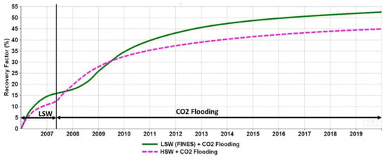
Figure 13.
LSW + CO2 flooding vs. HSW + CO2 flooding at field scale [145].
Very limited simulation work has been performed with respect to CO2 LSWAG injection in carbonate [110,149,150]. Al-Shalabi et al. [151] conducted geochemical investigations using PHREEQC on the coupling effect of CO2, low salinity water, and carbonate reservoir rock (calcite, dolomite, and anhydrite) at reservoir condition. The geochemical analysis indicates that carbonate with high dolomite composition shows the most significant effect induced by CO2 and LSW and carbonate with high anhydrite composition are affected by only LSWI. Furthermore, Al-Shalabi et al. [149] performed numerical modeling in carbonate using a compositional and multiphase flow simulator (UTCOMP). Baker’s model is used for three phase relative permeability with a modified LSWI model in carbonate [152], whereas the effects of gravity and capillary are neglected. The residual oil saturation is selected from the minimum value of oil saturation due to CO2 injection and due to LSWI. Miscible CO2 LSWAG injection outperformed the other EOR methods including simultaneous WAG injection, continuous gas injection and tapered WAG injection in terms of oil recovery and CO2 utilization factor. They highlighted that CO2 controls the residual oil saturation and LSW boosts oil production rate through increment in oil relative permeability caused by wettability alteration. However, since this simulation package is not capable of modeling the geochemical reactions like ion exchange and mineral dissolution, the conclusion is limited.
Despite all these simulation studies trying to capture the features in a CO2 LSWAG injection, including CO2 dissolution and dispersion in oil and water, aqueous reactions, ion exchange, mineral dissolution/precipitation, and wettability alteration, the hysteresis effect has been ignored. The use of an accurate simulation model with hysteresis in relative permeability and capillarity contributes to better predicting the performance of CO2 LSWAG injection. Therefore, investigating CO2 LSWAG injection with hysteresis model, as well as history matching with experimental data could be considered for further research.
5.3. Proposed Mechanisms of CO2 LSWAG Injection
The proposed mechanisms of CO2 LSWAG injection are a combination of LSWI and CO2 WAG injection, as summarized in Figure 14. Al-Abri et al. [97] proposed that the improved oil recovery by immiscible CO2 LSWAG injection is due to mobility control and wettability alteration. The IFT between high salinity brine and oil reduces as CO2 is introduced, however, changes in the IFT of low salinity brine and oil are not noticeable, indicating that IFT reduction is not a dominant mechanism in this process. They also suggest MIE mechanism that Na+ substitutes the divalent cations (Ca2+ and Mg2+), accounts for the higher oil recovery when injecting monovalent NaCl brine compared to injection of KCl and MgCl2 brine. Teklu et al. [9] claimed that CO2 LSWAG injection improved oil recovery of conventional CO2 WAG injection by forming in situ carbonated water of higher CO2 saturation in the brine phase due to the higher CO2 solubility in low salinity water. This in situ carbonated water promotes wettability alteration towards more water-wet and CO2-brine IFT reduction, hence improved oil recovery. This is similar to the mechanism proposed by Aleidan et al. [91] for CO2 LSWAG injection in carbonate reservoir. Chaturvedi et al. [8] and AlQuraishi et al. [96] suggest that fines migration and wettability alteration, which are mechanisms for LSWI, might be the dominant mechanisms for increased oil recovery by CO2 LSWAG injection. The presence of clay minerals, especially kaolinite, is considered essential. However, this proposed mechanism is questioned by Zolfaghari et al. [7] as they achieved oil recovery in sandstone without kaolinite. Wettability alteration towards more water-wet by CO2 LSWAG injection is put forward by Al-Saedi et al. [95,98,153] as the mechanism. Moradpour et al. [99] proposed that CO2 LSWAG injection improves oil recovery in carbonate through higher CO2 dissolution in LSW which promotes oil mobilization by wettability alteration towards more water-wet and minimizing the contrast between oil and water density.
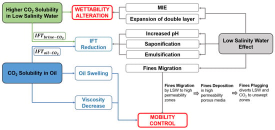
Figure 14.
Proposed combined mechanisms of LSWI and CO2 WAG injection in sandstone.
Based on the proposed mechanisms, wettability alteration and mobility control might be considered as the dominant mechanisms in CO2 LSWAG injection. However, some investigations [10,11] showed that CO2 salted out due to increased salinity, leading to better mobility control and LSE was not observed. This could be due to the strongly water-wet initial wettability, which is not favorable for LSW.
Simulation studies conducted on CO2 LSWAG injection [6,145] suggest two possible mechanisms from combining LSWI and CO2 WAG injection:
(1) LSWI compensates the delayed production by CO2 WAG injection in the early stage, and CO2 WAG injection assists in promoting ion exchange and geochemical reactions for LSWI;
(2) Fines migration by LSWI increased oil recovery by plugging the high permeability porous media; hence, the absolute permeability in these layers is reduced. As CO2 is injected into the reservoir, it is then diverted and flow with the LSW to the unswept zones with low permeability to provide additional oil recovery.
However, there is a lack of experimental evidence to validate the assumption of water blockage induced by LSW. Therefore, more detailed studies should be carried out to understand the mechanisms and conditions where CO2 LSWAG injection will yield the highest recovery.
5.4. Working Conditions and Screening Criteria for CO2 LSWAG Injection
Based on the pervious core flooding experiments, the EOR potential of CO2 LSWAG injection is not always shown (Table 9). There are some general conditions which are essential for this hybrid method to work: (1) the presence of clay minerals; (2) initial wettability from intermediate-wet to oil-wet; (3) polar compounds of oil. As seen from Table 9, there is one case [7] showing EOR potential without clay presence. However, it is worth mentioning that heavy crude oil is used in this studying, indicating sufficient amount of polar compounds of oil. There are three cases showing no EOR potential even with clay presence. The main reason is because the initial wettability of the cores is strongly water-wet. The criteria listed might not guarantee the EOR potential of CO2 LSWAG injection since there might be times that the dominant effect is either CO2 or LSW. If the dominant effect is LSW, the presence of multivalent cations in formation brine should be added as one more requirement.

Table 9.
Summary of CO2 LSWAG injection EOR potential from core flooding experiments.
5.5. Research Gap
The cyclic nature and the three-phase flow during WAG add additional complexities to accurately model and forecast CO2 LSWAG performance in porous media. It is essential that the models are able to capture the saturation-direction and saturation-history dependency in three phase relative permeability and capillary pressure [154]. However, the proposed hysteresis models so far suffer from the limitation in modeling hysteresis when one phase disappears or appears due to mass transfer. In addition, using the current three phase hysteresis models for compositional simulation is complexed [154]. Even though hysteresis is more significant in non-wetting phase (gas), it may occur in wetting phase as well with up to two orders of magnitude difference in relative permeability at equivalent saturation [32]. Some experimental and simulation work investigated the effect of LSWI on capillary pressure hysteresis [155,156], LSE is more significant when more pronounced hysteresis effect in capillary pressure is observed. This microscale hysteresis effect may be ascribed to contact angle hysteresis related to wettability and capillary dynamics and can be influenced by the surface roughness and tortuosity in the reservoir. Therefore, more research can be carried out to investigate and develop a hysteresis model in CO2 LSWAG injection which captures the cyclic nature of CO2 WAG process, as well as LSWI, and then incorporate the hysteresis model with the compositional geochemical simulators for proper simulation of CO2 LSWAG injection. Moreover, the effect of wettability, ionic concentration and composition, mineral dissolution on the hysteresis effect during CO2 LSWAG injection might also be an open topic for investigation.
Due to the acidic effect of CO2, CO2 LSWAG process is likely to lower pH value compared to implementing LSWI alone [151]. The acidic effect contributes to the occurrence of mineral dissolution or precipitation, leading to changes in pore structures, surface roughness, tortuosity of flow path, and ion concentrations. These changes could further affect wettability, fines migration, and oil desorption. For carbonate reservoir or sandstone reservoir with high content of calcite cementation or anhydrite cementation, consideration of mineral dissolution and precipitation is essential. As discussed earlier, CO2 LSWAG injection has the potential for enhancing oil recovery. However, there is so far no research conducted at pore scale and nano scale to investigate the mechanisms and effect of different parameters, as well as intermolecular forces and thermodynamics of the geochemical reactions in the oil/brine/rock/CO2 system. Pore-scale micro-model or micro-CT experiments can assist in understanding whether clay is essential for the success of CO2 LSWAG injection with visualization since core flooding experiments conducted by Zolfaghari et al. [7] showed LSE in CO2 LSWAG injection in samples that are kaolinite-free.
5.6. Environmental Aspects of CO2
Commonly, sources of CO2 for EOR operations are classified into three categories: (1) natural sources, indicating naturally occurring underground accumulations of CO2 (purity is higher than 90%); (2) natural gas processing, where the produced gas contains significant amount of methane; (3) industrial processing, where CO2 is captured from industrial plants [157]. Before the development of CCUS (carbon capture, utilization and storage) integration, natural sources of CO2 are most-commonly used for oil enhancement. This brings about issues considering expenses and supply, as the long-distance transportation from the source site to the injection site is expensive and these CO2 source reservoirs have a finite capacity and some are being depleted. With the development of CCUS hubs for carbon capture from emitting sources, the source for CO2-assited EOR is gradually switching from natural source to industrial processing, captured CO2. This enables the oil and gas industry to address the global warming environmental issue and lower carbon emission.
6. Simulation Investigation on Hysteresis Effect
According to the research gap described in Section 5.5, investigation on the hysteresis effect during CO2 LSWAG process is void. To fill this research gap, we have carried out simulation studies of hysteresis effect on miscible CO2 LSWAG injection.
6.1. Modeling of CO2 LSWAG Injection and Hysteresis Effect
CO2 LSWAG injection process is modeled with a compositional simulator, CMG-GEMTM, capable of capturing the geochemical and mineral reactions, as well as the wettability alteration induced by low salinity water. Modeling of these reactions and wettability alteration has been well explained in the work conducted by Dang et al. [6] and Section 4.2. This simulator is also capable of modeling the hysteresis effect with options of two-phase Land and Carlson model and three-phase Larsen and Skauge model. To investigate the effect of hysteresis model and salinity on oil recovery, two-phase and three-phase hysteresis models are incorporated into CO2 LSWAG injection modeling. The first approach is to use the bounding drainage and imbibition curves (Stone I) along with the two-phase Carlson hysteresis model [158]. The second approach is to use the three-phase hysteresis model developed by Larsen and Skauge [131] along with Stone I relative permeability correlation. Differences in the hysteresis effects are compared in terms of oil recovery. The impact of the salinity on hysteresis effect in terms of oil recovery is also investigated.
6.1.1. Hysteresis Modeling
The two-phase Land and Carlson model and three-phase Larsen and Skauge model are incorporated in CMG-GEMTM simulator for modeling hysteresis effect in WAG process. This section gives a brief description of the two models.
The two-phase Land and Carlson hysteresis model [158,159] are founded on Land’s trapping model [160]. In the Land’s model, gas saturation is separated into trapped gas saturation and free gas saturation. The trapped gas saturation, , (non-wetting phase) is computed as
where, is critical gas saturation, is maximum gas saturation at the flow reversal, and C is Land’s trapping parameter. The free gas saturation () contributing to the flow is computed as a function of gas saturation () and trapped gas saturation as shown in Equation (9):
In this study, we consider the two-phase hysteresis model to follow the theory of Land and Carlson. In Carlson’s model, the scanning curve is parallel to the input imbibition curve and can only be applied to the non-wetting (gas) phase as shown in Figure 15. The solid curves are the gas relative permeability input for the imbibition and drainage processes obtained from laboratory experiment. The gas relative permeability on the drainage to imbibition scanning curve, the dashed line for instance (Figure 15), is computed with Equation (10):
where, is the gas relative permeability on the imbibition curve and is the gas relative permeability on the drainage curve.
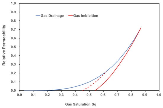
Figure 15.
Carlson hysteresis model on the non-wetting gas phase.
The three-phase hysteresis model implemented in this study is based on the model from Larsen and Skauge [131]. The primary gas relative permeability curve is used together with Land’s model to generate scanning curves. If the gas saturation decreases once again, a secondary drainage curve will be generated as follows:
where, is the input gas relative permeability, is the input gas relative permeability at the start of the secondary drainage, is the connate water saturation, is the water saturation at the start of the secondary drainage, is the gas relative permeability at the start of the secondary drainage, and is the gas relative permeability reduction factor.
For the three-phase scenario, there would be significant reduction in water mobility compared to its original mobility in the oil/water system after the injection of gas, [128]. Therefore, for an imbibition process with increasing water saturation, interpolation is carried out between the two-phase and three-phase inputs (Figure 16) with Equation (12) to calculate the imbibition relative permeability ():
where, is the water relative permeability from the two-phase curve, is from the three-phase curve, and is the gas saturation in the beginning of the imbibition process.
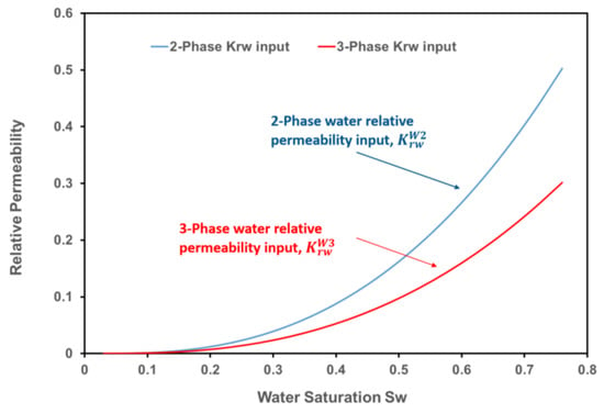
Figure 16.
Phase and 3-Phase relative permeability input for the Larsen and Skauge model.
6.1.2. Core-Scale Model and LSWI Description
A composite core-scale model (Figure 17) with properties shown in Table 10 is built for this simulation study. The initial water saturation is equal to connate water saturation, 0.03. The API oil gravity is 32. The WAG ratio is set to be 1:1 as most of the experimental results show that this WAG ratio delivers the best performance in terms of oil recovery [4].
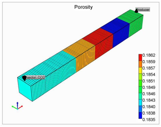
Figure 17.
Composite core-scale model.

Table 10.
Properties and operational parameters of the core-scale model.
Figure 18 shows the relative permeability curves obtained from experimental data representing high and low salinity water. These two sets of curves are used for interpolation to model wettability alteration by LSWI. The relative permeability curves for high salinity water represent a more oil-wet condition, and those for low salinity water represent a more water-wet condition. Low salinity effect is modeled with a shift in the relative permeability curves from oil-wet to water-wet. Equivalent fraction of Na+ on the negatively charged surface is used as interpolant for relative permeability interpolation. The composition of formation water initially present in the reservoir is listed in Table 11, which is used as input for the core-scale model. The compositions of the low salinity water and seawater in the water injection cycles are shown in Table 11. The salinity of the low salinity water is chosen to be 2000 ppm, which is within the salinity range for LSWI [58].
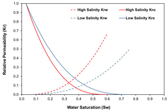
Figure 18.
Relative permeability for high and low salinity water.

Table 11.
Composition of formation and injection water.
6.1.3. Modeling Investigation Approach
With the core-scale model, LSWI and hysteresis modeling in place, investigation on hysteresis effect on CO2 LS WAG and seawater WAG (SWAG) injection is evaluated through two-phase Land and Carlson model and three-phase Larsen and Skauge model using Stone I relative permeability correlation [131]. The main input for the Land and Carlson model is the bounding drainage curve and Land parameter, and for Larsen and Skauge model is primary drainage curve, Land parameter, and gas relative permeability reduction factor.
The effect of hysteresis model on oil recovery is investigated with Land parameter of 0.8 as recommended by Egermann et al. [135] and gas relative permeability reduction factor of 3.32 as suggested by Hosseini et al. [161]. The effect of salinity on three-phase hysteresis is also investigated with varying salinities (2000, 5000, 10,000, 20,000, 35,746 ppm). All these cases are conducted with WAG ratio of 1:1 and are simulated as secondary recovery mode. Capillary pressure is ignored in this study.
6.2. Results and Discussion
This section presents the results from the core-scale simulation and the discussion on the effect of hysteresis model and salinity on CO2 WAG injection process.
6.2.1. Effect of Hysteresis Model on Oil Recovery
Table 12 summarizes the oil recovery factor with and without hysteresis for CO2 LSWAG injection (2000 ppm low salinity water) and CO2 WAG injection (35,746 ppm seawater). The two base cases are the CO2 LSWAG and WAG injection with no hysteresis.

Table 12.
Summary of simulation results.
It is observed from Table 12 that the differences in oil recovery factor due to hysteresis is not significant. It is worth noting that there is a slight increase in recovery factor with 3-Phase hysteresis in CO2 WAG injection (#1 and #3), however, the opposite trend is observed for CO2 LS WAG injection (#4 and #6). Comparing the differences of 2-Phase Carlson and 3-Phase Larsen and Skauge model in CO2 WAG injection (#1, #2, and #3), 2-Phase model has no effect on oil recovery, whereas a slight increase is observed with 3-Phase model. With CO2 LS WAG injection (#4, #5 and #6), applying 2-Phase and 3-Phase model makes no difference.
Despite the negligible differences in oil recovery due to hysteresis effect, different changing trend is seen for injection water with different salinities (2000 ppm and 35,746 ppm). This indicates that salinity of the injection water might also play a role in cyclic WAG injection process, which is further discussed in the next section.
6.2.2. Effect of Salinity
The effect of salinity is investigated through varying injection water salinities from 2000 ppm to 35,746 ppm (seawater) in the CO2 WAG process (2000 ppm, 5000 ppm, 10,000 ppm, 20,000 ppm, and 35,746 ppm). Figure 19 shows the results with oil recoveries plotted against salinities.
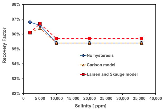
Figure 19.
Oil recovery factor for CO2 WAG injection hysteresis simulations with different salinities.
Even though changes in oil recovery with respect to salinity is relatively small in this core-scale simulation, the changing trend is worth mentioning since the effect might be magnified in the field scale. From Figure 19, oil recovery of CO2 WAG injection with no hysteresis remains unchanged from 35,746 ppm to 10,000 ppm and increases with decreasing salinity from 10,000 ppm to 2000 ppm due to low salinity effect. However, with 2-Phase and 3-Phase hysteresis models, the changing trend of oil recovery varies in the range of 2000 ppm to 10,000 ppm. Instead of a constant increase in oil recovery from 10,000 ppm to 2000 ppm, oil recovery slightly increases to a peak from 10,000 ppm to 5000 ppm and decreases from 5000 ppm to 2000 ppm. Could this be caused by the differences in LSE with different salinities?
Figure 20 shows that oil recovery by only water injection increases from 100,000 ppm to 2000 ppm. Thus, the trend changing in oil recovery of CO2 WAG injection might be mainly due to the hysteresis effect. CO2 LSWAG injection with 5000 ppm salinity in injection water results in the highest oil recovery compared to 2000 ppm salinity, even though injecting 2000 ppm water achieves the highest in LSWI (Figure 20).
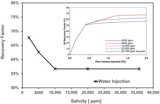
Figure 20.
Oil recovery by water injection with varying salinities.
It can be inferred from the simulation results that it is more accurate to include the effect of hysteresis in CO2 LSWAG injection modeling and optimization. Neglecting the hysteresis effect might not lead to significant error in core-scale simulation. However, if the modeling and optimization are performed at reservoir scale, excluding hysteresis could result in choosing wrong operational parameters and salinities.
7. Conclusions
This paper presents a review of the effect of different parameters on CO2 LSWAG injection, and the independent and combined mechanisms of LSWI and CO2 WAG injection. A simulation investigation on the hysteresis effect in CO2 LSWAG injection has been conducted to fill the identified research gap. The following are the conclusions and recommendations based on this literature review and simulation study:
- The EOR potential of CO2 LSWAG injection has been confirmed by laboratory experiments and simulation studies. Initial wettability, the composition and salinity of injection and formation brine, WAG parameters, and reservoir pressure and temperature determine the success of this method;
- Laboratory experiments suggest that mobility control and wettability alteration (towards more water-wet) could be the dominant mechanisms for CO2 LSWAG injection;
- Clay content might not be an essential requirement for EOR using CO2 LSWAG injection as EOR potential has been observed with core samples with no clay content and core samples with less than 0.5% or 2–6% clay have reported both oil recovery increase or no oil recovery increase. This could be because the low salinity effect in a CO2 LSWAG injection differs from LSWI alone. In a CO2 LSWAG injection, low salinity effect could be similar to a LSWI, or similar to carbonated water injection as lower salinity leads to higher CO2 solubility in water, resulting in in situ carbonated water effect for increased oil recovery.
- Simulation studies proposed two effects for CO2 LSWAG injection. One is that LSWI could potentially compensate for the delayed production by CO2 WAG injection in the early stage, and the injection of CO2 promotes ion exchange and geochemical reactions for LSWI due to its reaction with water and calcite minerals. The other one is that fines migration, and subsequent water blockage induced by fines plugging, divert the flow path to unswept low permeability zones. Due to the lack of experimental evidence, more laboratory experiments, especially pore-scale studies, are recommended to investigate the driving forces and mechanisms for improved oil recovery by CO2 LSWAG injection;
- There is no consensus as to which mechanisms are dominant in improving oil recovery during LSWI, and limited research on the interactions between CO2, crude oil, brine and reservoir rocks. Hence, extensive laboratory studies and simulations on a field scale should be conducted prior to any field-scale application of CO2 LSWAG injection;
- Development of a more reliable CO2 LSWAG injection model is necessary, considering geochemical interactions of the crude oil/brine/rock, three-phase relative permeability, capillary pressure, and hysteresis effect;
- Further investigations are required to thoroughly understand the effect of interactions between crude oil, low salinity water, rock minerals and CO2 on wettability modification during CO2 LSWAG injection;
- Despite the existing challenges, this hybrid technique has the potential to improve oil recovery at low cost in both offshore and onshore reservoirs with ongoing or planned water flooding and CO2 WAG injection projects; and
- Our simulation investigation on the hysteresis effect indicates that it is more accurate to include hysteresis in CO2 LSWAG injection modeling and optimization. In our study with respect salinity effect on oil recovery considering hysteresis, higher oil recovery is obtained with salinity of 5000 ppm instead of 2000 ppm, indicating that lower salinity in a CO2 LSWAG injection with hysteresis effect considered might not lead to higher oil recovery. Even though the hysteresis effect is not significant at core scale, excluding it at reservoir scale might lead to large errors in oil recovery prediction as well as operational parameters and salinity optimization. Moreover, more laboratory data with respect to the imbibition and drainage curves considering different salinities is also required to better model the CO2 LSWAG injection process.
Author Contributions
Conceptualization, S.M. and L.A.J.; methodology, S.M.; software, S.M.; validation, S.M.; formal analysis, S.M.; investigation, S.M.; resources, S.M.; data curation, S.M.; writing—original draft preparation, S.M.; writing—review and editing, S.M. and L.A.J.; visualization, S.M.; supervision, L.A.J.; project administration, L.A.J.; funding acquisition, L.A.J. All authors have read and agreed to the published version of the manuscript.
Funding
This research was funded by Chevron Canada, Hibernia Management and Development Company (HMDC), Petroleum Research Newfoundland and Labrador (PRNL), Natural Sciences and Engineering Research Council of Canada (NSERC), the Province of Newfoundland and Labrador, and Mitacs.
Acknowledgments
The authors would like to thank the Hibernia Management and Development Company (HMDC), Chevron Canada Ltd., Petroleum Research Newfoundland and Labrador (PRNL), the Natural Sciences and Engineering Research Council of Canada (NSERC), the Province of Newfoundland and Labrador, and Mitacs for financial support. We thank our colleagues in the Hibernia EOR Research Group for their technical support.
Conflicts of Interest
The authors declare no conflict of interest. The funders had no role in the design of the study; in the collection, analyses, or interpretation of data; in the writing of the manuscript, or in the decision to publish the results.
Nomenclature
| Acronyms | |
| API | American Petroleum Institute |
| BHP | Bottom hole pressure |
| Ca2+ | Calcium ion |
| CaCl2 | Calcium chloride |
| Cl− | Chloride ion |
| CMG | Computer Modeling Group |
| CO2 | Carbon dioxide |
| COBR | Crude-oil/brine/rock |
| DECE | Designed exploration-controlled evolution |
| EOR | Enhanced Oil Recovery |
| GA | Genetic algorithm |
| HCO3− | Bicarbonate ion |
| H2CO3 | Carbonic acid |
| HS | High salinity |
| HSW | High salinity water |
| IFT | Interfacial tension |
| LPG | Liquified petroleum gases |
| LS | Low salinity |
| LSE | Low salinity effect |
| LSW | Low salinity water |
| LSWAG | Low salinity water-alternating-gas |
| LSWI | Low salinity water injection |
| K+ | Potassium ion |
| KCl | Potassium chloride |
| Krg | Gas relative permeability |
| Na+ | Sodium ion |
| NaCl | Sodium chloride |
| Na2SO4 | Sodium sulfate |
| md | Milli Darcy |
| Mg2+ | Magnesium ion |
| MgCl2 | Magnesium chloride |
| MIE | Multi-component ionic exchange |
| MMP | Minimum miscible pressure |
| MSW | Modified seawater |
| NPV | Net present value |
| OOIP | Original oil in place |
| ppm | Parts per million |
| PSO | Particle swarm optimization |
| PV | Pore volume |
| RSM | Response surface methodology |
| Sg | Gas saturation |
| Sgcrit | Critical gas saturation |
| Sgf | Free gas saturation |
| Sg,max | Maximum gas saturation at the flow reversal |
| Sgr | Trapped gas saturation |
| SO42− | Sulfate ion |
| Sw | Water saturation |
| TDS | Total dissolved solids |
| UTCOMP | Compositional and multiphase flow simulator |
| WAG | Water-alternating-gas |
| WI | Wettability index |
| 0NaCl | Without NaCl |
| 0NaCl-d5Ca | Without NaCl and 5-time diluted Ca2+ |
| 0NaCl-d5Mg | Without NaCl and 5-time diluted Mg2+ |
| 0NaCl-d5SO4 | Without NaCl and 5-time diluted SO42− |
| Variables and parameters | |
| M | Mobility ratio |
| V | Volume fraction |
| Greek letters | |
| ζ | Zeta potential |
| λ | Mobility |
| θ | Contact angle |
| β | Coefficient |
| ν | Velocity |
References
- Sheng, J.J. Enhanced Oil Recovery Field Case Studies; Gulf Professional Publishing: Woburn, MA, USA, 2013. [Google Scholar]
- Al-Murayri, M.; Al-Mayyan, H.; Moudi, K.; Al-Ajmi, F.; Pitts, D.; Wyatt, M.; French, K.; Surtek, J.; Dean, E. Chemical EOR Economic Evaluation in a Low Oil Price Environment: Sabriyah Lower Burgan Reservoir Case Study. In Proceedings of the SPE EOR Conference at Oil and Gas West Asia, Muscat, Oman, 26–28 March 2018; Society of Petroleum Engineers: Richardson, TX, USA, 2018. [Google Scholar]
- Sheng, J. Critical review of low-salinity waterflooding. J. Pet. Sci. Eng. 2014, 120, 216–224. [Google Scholar] [CrossRef]
- Afzali, S.; Rezaei, N.; Zendehboudi, S. A comprehensive review on enhanced oil recovery by water alternating gas (WAG) injection. Fuel 2018, 227, 218–246. [Google Scholar] [CrossRef]
- Dang, C.T.; Nghiem, L.X.; Chen, Z.; Nguyen, N.T.; Nguyen, Q.P. CO2 low salinity water alternating gas: A new promising approach for enhanced oil recovery. In Proceedings of the SPE Improved Oil Recovery Symposium, Tulsa, OK, USA, 14–18 April 2014; Society of Petroleum Engineers: Richardson, TX, USA, 2014. [Google Scholar]
- Dang, C.; Nghiem, L.; Nguyen, N.; Chen, Z.; Nguyen, Q. Evaluation of CO2 low salinity water-alternating-gas for enhanced oil recovery. J. Nat. Gas Sci. Eng. 2016, 35, 237–258. [Google Scholar] [CrossRef]
- Zolfaghari, H.; Zebarjadi, A.; Shahrokhi, O.; Ghazanfari, M.H. An experimental study of CO2-low salinity water alternating gas injection in sandstone heavy oil reservoirs. Iran. J. Oil Gas Sci. Technol. 2013, 2, 37–47. [Google Scholar]
- Chaturvedi, K.R.; Ravilla, D.; Keleem, W.; Jadhawar, P.; Sharma, T. Impact of Low Salinity Water Injection on CO2 Storage and Oil Recovery for Improved CO2 Utilization. Chem. Eng. Sci. 2020, 229, 11. [Google Scholar] [CrossRef]
- Teklu, T.W.; Alameri, W.; Graves, R.M.; Kazemi, H.; Al-sumaiti, A.M. Low-salinity water-alternating-CO2 flooding enhanced oil recovery: Theory and experiments. In Proceedings of the Abu Dhabi International Petroleum Exhibition and Conference, Abu Dhabi, United Arab Emirates, 31 October–3 November 2014; Society of Petroleum Engineers: Richardson, TX, USA, 2014. [Google Scholar]
- Ramanathan, R.; Shehata, A.; Nasr-El-Din, H. Water Alternating CO2 Injection Process-Does Modifying the Salinity of Injected Brine Improve Oil Recovery? In Proceedings of the OTC Brasil, Rio de Janeiro, Brazil, 27 October 2015; Offshore Technology Conference: Rio de Janeiro, Brazil, 2015. [Google Scholar]
- Jiang, H.; Nuryaningsih, L.; Adidharma, H. The effect of salinity of injection brine on water alternating gas performance in tertiary miscible carbon dioxide flooding: Experimental study. In Proceedings of the SPE Western Regional Meeting, Bakersfield, CA, USA, 5 November 2010; Society of Petroleum Engineers: Richardson, TX, USA, 2010. [Google Scholar]
- Lake, L.W. Enhanced Oil Recovery; Prentice Hall: Englewood Cliffs, NJ, USA, 1989. [Google Scholar]
- Holm, L.; Josendal, V. Mechanisms of oil displacement by carbon dioxide. J. Pet. Technol. 1974, 26, 1427–1438. [Google Scholar] [CrossRef]
- Perera, M.S.A.; Gamage, R.P.; Rathnaweera, T.D.; Ranathunga, A.S.; Koay, A.; Choi, X. A review of CO2-enhanced oil recovery with a simulated sensitivity analysis. Energies 2016, 9, 481. [Google Scholar] [CrossRef]
- Czernichowski-Lauriol, I.; Rochelle, C.; Gaus, I.; Azaroual, M.; Pearce, J.; Durst, P. Geochemical interactions between CO2, pore-waters and reservoir rocks. In Advances in the Geological Storage of Carbon Dioxide; Springer: Berlin/Heidelberg, Germany, 2006; pp. 157–174. [Google Scholar]
- Crawford, H.; Neill, G.; Bucy, B.; Crawford, P.B. Carbon dioxide-a multipurpose additive for effective well stimulation. J. Pet. Technol. 1963, 15, 237–242. [Google Scholar] [CrossRef]
- Ahmed, T. Equations of State and PVT Analysis; Elsevier: Amsterdam, The Netherlands, 2013. [Google Scholar]
- Verma, M.K. Fundamentals of Carbon Dioxide-Enhanced Oil Recovery (CO2-EOR): A Supporting Document of the Assessment Methodology for Hydrocarbon Recovery Using CO2-EOR Associated with Carbon Sequestration; US Department of the Interior, US Geological Survey: Washington, DC, USA, 2015.
- Holtz, M.H.; Nance, P.K.; Finley, R.J. Reduction of greenhouse gas emissions through CO2 EOR in Texas. Environ. Geosci. 2001, 8, 187–199. [Google Scholar] [CrossRef]
- Zhang, H.; Hou, D.; Li, K. An improved CO2-crude oil minimum miscibility pressure correlation. J. Chem. 2015, 2015, 175940. [Google Scholar] [CrossRef]
- Jarrell, P.M.; Fox, C.E.; Stein, M.H.; Webb, S.L. Practical Aspects of CO2 Flooding; Society of Petroleum Engineers: Richardson, TX, USA, 2002; Volume 22. [Google Scholar]
- Welker, J. Physical properties of carbonated oils. J. Pet. Technol. 1963, 15, 873–876. [Google Scholar] [CrossRef]
- Chung, F.T.; Jones, R.A.; Burchfield, T. Recovery of viscous oil under high pressure by CO2 displacement: A laboratory study. In Proceedings of the International Meeting on Petroleum Engineering, Tianjin, China, 1–4 November 1988; Society of Petroleum Engineers: Richardson, TX, USA, 1988. [Google Scholar]
- Chung, F.T.; Jones, R.A.; Nguyen, H.T. Measurements and correlations of the physical properties of CO2-heavy crude oil mixtures. SPE Reserv. Eng. 1988, 3, 822–828. [Google Scholar] [CrossRef]
- DeRuiter, R.; Nash, L.; Singletary, M. Solubility and displacement behavior of a viscous crude with CO2 and hydrocarbon gases. SPE Reserv. Eng. 1994, 9, 101–106. [Google Scholar] [CrossRef]
- Kokal, S.L.; Sayegh, S.G. Phase behavior and physical properties of CO2-saturated heavy oil and its constitutive fractions: Experimental data and correlations. J. Pet. Sci. Eng. 1993, 9, 289–302. [Google Scholar] [CrossRef]
- Hatzignatiou, D.; Lu, Y. Feasibility Study of CO2 Immiscible Displacement Process In Heavy Oil Reservoirs. In Proceedings of the Annual Technical Meeting, New Orleans, LA, USA, 25–28 September 1994; Petroleum Society of Canada: Richardson, TX, USA, 1994. [Google Scholar]
- Yang, C.; Gu, Y. Diffusion coefficients and oil swelling factors of carbon dioxide, methane, ethane, propane, and their mixtures in heavy oil. Fluid Phase Equilibria 2006, 243, 64–73. [Google Scholar] [CrossRef]
- Klins, M.A.; Ali, S. Heavy oil production by carbon dioxide injection. J. Can. Pet. Technol. 1982, 21, 82-05-06. [Google Scholar] [CrossRef]
- Svrcek, W.Y.; Mehrotra, A.K. Gas solubility, viscosity and density measurements for Athabasca bitumen. J. Can. Pet. Technol. 1982, 21, 82-04-02. [Google Scholar] [CrossRef]
- Gao, C.; Li, X.; Guo, L.; Zhao, F. Heavy oil production by carbon dioxide injection. Greenh. Gases: Sci. Technol. 2013, 3, 185–195. [Google Scholar] [CrossRef]
- Touray, S. Effect of water alternating gas injection on ultimate oil recovery. Master Eng. Dalhous. Univ. 2013, 25, 11–15. [Google Scholar]
- Wang, G.C. A laboratory study of the effects of CO2 injection sequence on tertiary oil recovery. Soc. Pet. Eng. J. 1980, 20, 278–280. [Google Scholar] [CrossRef]
- Bennion, D.B.; Thomas, F.B.; Jamaluddin, A.; Ma, T. The effect of trapped critical fluid saturations on reservoir permeability and conformance. In Proceedings of the Annual Technical Meeting of the Petroleum Society of CIM, Calgary, AB, Canada, 28–31 May 1998; pp. 8–10. [Google Scholar]
- Zuo, L.; Chen, Y.; Dengen, Z.; Kamath, J. Three-phase relative permeability modeling in the simulation of WAG injection. SPE Reserv. Eval. Eng. 2014, 17, 326–339. [Google Scholar] [CrossRef]
- Duchenne, S.; de Loubens, R.; Petitfrere, M.; Joubert, T. Modeling and simultaneous history-matching of multiple WAG coreflood experiments at reservoir conditions. In Proceedings of the Abu Dhabi International Petroleum Exhibition and Conference, Abu Dhabi, United Arab Emirates, 9–12 November 2015; Society of Petroleum Engineers: Richardson, TX, USA, 2015. [Google Scholar]
- Bernard, G.G. Effect of floodwater salinity on recovery of oil from cores containing clays. In Proceedings of the SPE California Regional Meeting, Los Angeles, CA, USA, 26 October 1967; Society of Petroleum Engineers: Richardson, TX, USA, 1967. [Google Scholar]
- Jadhunandan, P.; Morrow, N.R. Effect of wettability on waterflood recovery for crude-oil/brine/rock systems. SPE Reserv. Eng. 1995, 10, 40–46. [Google Scholar] [CrossRef]
- Jadhunandan, P.P. Effects of Brine Composition, Crude Oil, and Aging Conditions on Wettability and Oil Recovery. Ph.D. Thesis, Department of Petroleum Engineering, New Mexico Institute of Mining & Technology, Socorro, NM, USA, 1990. [Google Scholar]
- Morrow, N.; Valat, M.; Yidliz, H. Effect of brine composition on recovery of an Alaskan crude oil by waterflooding. In Proceedings of the Annual Technical Meeting, San Diego, CA, USA, 22–26 January 1996; Society of Petroleum Engineers: Richardson, TX, USA, 1996. [Google Scholar]
- Tang, G.Q.; Morrow, N.R. Influence of brine composition and fines migration on crude oil/brine/rock interactions and oil recovery. J. Pet. Sci. Eng. 1999, 24, 99–111. [Google Scholar] [CrossRef]
- Tang, G.; Morrow, N.R. Salinity, temperature, oil composition, and oil recovery by waterflooding. SPE Reserv. Eng. 1997, 12, 269–276. [Google Scholar] [CrossRef]
- Webb, K.; Black, C.; Al-Ajeel, H. Low salinity oil recovery-log-inject-log. In Proceedings of the Middle East Oil Show, Sakhir, Bahrain, 9 June 2003; Society of Petroleum Engineers: Richardson, TX, USA, 2003. [Google Scholar]
- Webb, K.J.; Black, C.J.J.; Tjetland, G. A laboratory study investigating methods for improving oil recovery in carbonates. In Proceedings of the International Petroleum Technology Conference, Doha, Qatar, 21 November 2005. [Google Scholar]
- Gupta, R.; Smith, G.G.; Hu, L.; Willingham, T.; Lo Cascio, M.; Shyeh, J.J.; Harris, C.R. Enhanced waterflood for carbonate reservoirs-impact of injection water composition. In Proceedings of the SPE Middle East Oil and Gas Show and Conference, Manama, Bahrain, 25–28 September 2011; Society of Petroleum Engineers: Richardson, TX, USA, 2011. [Google Scholar]
- Soraya, B.; Malick, C.; Philippe, C.; Bertin, H.J.; Hamon, G. Oil recovery by low-salinity brine injection: Laboratory results on outcrop and reservoir cores. In Proceedings of the SPE Annual Technical Conference and Exhibition, New Orleans, LA, USA, 4–7 October 2009; Society of Petroleum Engineers: Richardson, TX, USA, 2009. [Google Scholar]
- Ligthelm, D.J.; Gronsveld, J.; Hofman, J.; Brussee, N.; Marcelis, F.; van der Linde, H. Novel Waterflooding Strategy By Manipulation Of Injection Brine Composition. In Proceedings of the EUROPEC/EAGE Conference and Exhibition, Amsterdam, The Netherlands, 8–11 June 2009; Society of Petroleum Engineers: Richardson, TX, USA, 2009. [Google Scholar]
- Mahani, H.; Sorop, T.; Ligthelm, D.J.; Brooks, D.; Vledder, P.; Mozahem, F.; Ali, Y. Analysis of field responses to low-salinity waterflooding in secondary and tertiary mode in Syria. In Proceedings of the SPE Europec/EAGE Annual Conference and Exhibition, Aberdeen, UK, 6–8 September 2011; Society of Petroleum Engineers: Richardson, TX, USA, 2011. [Google Scholar]
- Romanuka, J.; Hofman, J.; Ligthelm, D.J.; Suijkerbuijk, B.; Marcelis, F.; Oedai, S.; Brussee, N.; van der Linde, H.; Aksulu, H.; Austad, T. Low salinity EOR in carbonates. In Proceedings of the SPE Improved Oil Recovery Symposium, Tulsa, OK, USA, 14–18 April 2012; Society of Petroleum Engineers: Richardson, TX, USA, 2012. [Google Scholar]
- Vledder, P.; Gonzalez, I.E.; Carrera Fonseca, J.C.; Wells, T.; Ligthelm, D.J. Low salinity water flooding: Proof of wettability alteration on a field wide scale. In Proceedings of the SPE Improved Oil Recovery Symposium, Tulsa, OK, USA, 24–28 April 2010; Society of Petroleum Engineers: Richardson, TX, USA, 2010. [Google Scholar]
- Nasralla, R.A.; Bataweel, M.A.; Nasr-El-Din, H.A. Investigation of wettability alteration and oil-recovery improvement by low-salinity water in sandstone rock. J. Can. Pet. Technol. 2013, 52, 144–154. [Google Scholar] [CrossRef]
- Skrettingland, K.; Holt, T.; Tweheyo, M.T.; Skjevrak, I. Snorre Low-Salinity-Water Injection—Coreflooding Experiments and Single-Well Field Pilot. SPE Reserv. Eval. Eng. 2011, 14, 182–192. [Google Scholar] [CrossRef]
- RezaeiDoust, A.; Puntervold, T.; Strand, S.; Austad, T. Smart water as wettability modifier in carbonate and sandstone: A discussion of similarities/differences in the chemical mechanisms. Energy Fuels 2009, 23, 4479–4485. [Google Scholar] [CrossRef]
- Yousef, A.A.; Al-Saleh, S.H.; Al-Kaabi, A.; Al-Jawfi, M.S. Laboratory investigation of the impact of injection-water salinity and ionic content on oil recovery from carbonate reservoirs. SPE Reserv. Eval. Eng. 2011, 14, 578–593. [Google Scholar] [CrossRef]
- Morrow, N.; Buckley, J. Improved oil recovery by low-salinity waterflooding. J. Pet. Technol. 2011, 63, 106–112. [Google Scholar] [CrossRef]
- Boston, W.G.; Brandner, C.F.; Foster, W.R. Recovery of Oil by Waterflooding from an Argillaceous, Oil-Containing Subterranean Formation. U.S. Patent 3,470,956, 7 October 1969. [Google Scholar]
- Song, W.; Kovscek, A.R. Direct visualization of pore-scale fines migration and formation damage during low-salinity waterflooding. J. Nat. Gas Sci. Eng. 2016, 34, 1276–1283. [Google Scholar] [CrossRef]
- Austad, T.; RezaeiDoust, A.; Puntervold, T. Chemical mechanism of low salinity water flooding in sandstone reservoirs. In Proceedings of the SPE Improved Oil Recovery Symposium, Tulsa, OK, USA, 24–28 April 2010; Society of Petroleum Engineers: Richardson, TX, USA, 2010. [Google Scholar]
- Velde, B. Origin and Mineralogy of Clays: Clays and the Environment; Springer Science & Business Media: New York, NY, USA, 2013. [Google Scholar]
- McGuire, P.; Chatham, J.; Paskvan, F.; Sommer, D.; Carini, F. Low salinity oil recovery: An exciting new EOR opportunity for Alaska’s North Slope. In Proceedings of the SPE Western Regional Meeting, Irvine, CA, USA, 30 March–1 April 2005; Society of Petroleum Engineers: Richardson, TX, USA, 2005. [Google Scholar]
- Fredriksen, S.; Rognmo, A.; Sandengen, K.; Fernø, M. Wettability effects on osmosis as an oil-mobilization mechanism during low-salinity waterflooding. Petrophysics 2017, 58, 28–35. [Google Scholar]
- Fakcharoenphol, P.; Kurtoglu, B.; Kazemi, H.; Charoenwongsa, S.; Wu, Y.S. The effect of osmotic pressure on improve oil recovery from fractured shale formations. In Proceedings of the SPE Unconventional Resources Conference, Vienna, Austria, 25–27 February 2014; Society of Petroleum Engineers: Richardson, TX, USA, 2014. [Google Scholar]
- Kurtoglu, B. A rock and fluid study of middle Bakken formation: Key to enhanced oil recovery. In Proceedings of the 76th EAGE Conference and Exhibition 2014, Amsterdam, The Netherlands, 16–19 June 2014; European Association of Geoscientists & Engineers: The Hague, The Netherlands, 2014; pp. 1–5. [Google Scholar]
- Sandengen, K.; Arntzen, O. Osmosis during low salinity water flooding. In Proceedings of the IOR 2013-17th European Symposium on Improved Oil Recovery, St. Petersburg, Russia, 16–18 April 2013; European Association of Geoscientists & Engineers: The Hague, The Netherlands, 2013; p. cp-342-00015. [Google Scholar]
- Sandengen, K.; Kristoffersen, A.; Melhuus, K.; Jøsang, L.O. Osmosis as mechanism for low-salinity enhanced oil recovery. SPE J. 2016, 21, 1227–1235. [Google Scholar] [CrossRef]
- Morrow, N.R.; Tang, G.Q.; Valat, M.; Xie, X. Prospects of improved oil recovery related to wettability and brine composition. J. Pet. Sci. Eng. 1998, 20, 267–276. [Google Scholar] [CrossRef]
- Morrow, N.R. Wettability and its effect on oil recovery. J. Pet. Technol. 1990, 42, 1476–1484. [Google Scholar] [CrossRef]
- Berg, S.; Cense, A.; Jansen, E.; Bakker, K. Direct experimental evidence of wettability modification by low salinity. Petrophysics 2010, 51, SPWLA-2010-v51n5a3. [Google Scholar]
- Nasralla, R.A.; Bataweel, M.A.; Nasr-El-Din, H.A. Investigation of wettability alteration by low salinity water. In Proceedings of the Offshore Europe, Aberdeen, UK, 19–21 July 2011; Society of Petroleum Engineers: Richardson, TX, USA, 2011. [Google Scholar]
- Lager, A.; Webb, K.J.; Black, C.; Singleton, M.; Sorbie, K.S. Low salinity oil recovery-an experimental investigation1. Petrophysics 2008, 49, SPWLA-2008-v49n1a2. [Google Scholar]
- Al-Saedi, H.N.; Brady, P.V.; Flori, R.E.; Heidari, P. Insights into the role of clays in low salinity water flooding in sand columns. J. Pet. Sci. Eng. 2019, 174, 291–305. [Google Scholar] [CrossRef]
- Mitchell, J.K.; Soga, K. Fundamentals of Soil Behavior; John Wiley & Sons: New York, NY, USA, 2005; Volume 3. [Google Scholar]
- van Olphen, H. An introduction to clay colloid chemistry. Soil Sci. 1964, 97, 290. [Google Scholar] [CrossRef]
- Pu, H.; Xie, X.; Yin, P.; Morrow, N.R. Low salinity waterflooding and mineral dissolution. In Proceedings of the SPE Annual Technical Conference and Exhibition, New Orleans, LA, USA, 2 February 2010; OnePetro: Richardson, TX, USA, 2010. [Google Scholar]
- Katende, A.; Sagala, F. A critical review of low salinity water flooding: Mechanism, laboratory and field application. J. Mol. Liq. 2019, 278, 627–649. [Google Scholar] [CrossRef]
- Al-Shalabi, E.W.; Sepehrnoori, K. A comprehensive review of low salinity/engineered water injections and their applications in sandstone and carbonate rocks. J. Pet. Sci. Eng. 2016, 139, 137–161. [Google Scholar] [CrossRef]
- Yue, L.; Pu, W.; Zhao, S.; Zhang, S.; Ren, F.; Xu, D. Insights into mechanism of low salinity water flooding in sandstone reservoir from interfacial features of oil/brine/rock via intermolecular forces. J. Mol. Liq. 2020, 313, 113435. [Google Scholar] [CrossRef]
- Mahmoud, M.; Nasr-El-Din, H. Challenges during shallow and deep carbonate reservoirs stimulation. J. Energy Resour. Technol. 2015, 137, 012902. [Google Scholar] [CrossRef]
- Yue, W.; Yilin Wang, J. Feasibility of waterflooding for a carbonate oil field through whole-field simulation studies. J. Energy Resour. Technol. 2015, 137, 064501. [Google Scholar] [CrossRef]
- Standnes, D.C.; Austad, T. Wettability alteration in chalk: 2. Mechanism for wettability alteration from oil-wet to water-wet using surfactants. J. Pet. Sci. Eng. 2000, 28, 123–143. [Google Scholar] [CrossRef]
- Austad, T. Water-based EOR in carbonates and sandstones: New chemical understanding of the EOR potential using “Smart Water”. In Enhanced Oil Recovery Field Case Studies; Elsevier: Amsterdam, The Netherlands, 2013; pp. 301–335. [Google Scholar]
- Yousef, A.A.; Al-Saleh, S.; Al-Jawfi, M.S. The impact of the injection water chemistry on oil recovery from carbonate reservoirs. In Proceedings of the SPE EOR Conference at Oil and Gas West Asia, Muscat, Oman, 16–18 April 2012; Society of Petroleum Engineers: Richardson, TX, USA, 2012. [Google Scholar]
- Strand, S.; Høgnesen, E.J.; Austad, T. Wettability alteration of carbonates—Effects of potential determining ions (Ca2+ and SO42−) and temperature. Colloids Surf. A Physicochem. Eng. Asp. 2006, 275, 1–10. [Google Scholar] [CrossRef]
- Strand, S.; Puntervold, T.; Austad, T. Effect of temperature on enhanced oil recovery from mixed-wet chalk cores by spontaneous imbibition and forced displacement using seawater. Energy Fuels 2008, 22, 3222–3225. [Google Scholar] [CrossRef]
- Zhang, P.; Tweheyo, M.T.; Austad, T. Wettability alteration and improved oil recovery in chalk: The effect of calcium in the presence of sulfate. Energy Fuels 2006, 20, 2056–2062. [Google Scholar] [CrossRef]
- Zhang, P.; Tweheyo, M.T.; Austad, T. Wettability alteration and improved oil recovery by spontaneous imbibition of seawater into chalk: Impact of the potential determining ions Ca2+, Mg2+, and SO42−. Colloids Surf. A: Physicochem. Eng. Asp. 2007, 301, 199–208. [Google Scholar] [CrossRef]
- Strand, S.; Austad, T.; Puntervold, T.; Høgnesen, E.J.; Olsen, M.; Barstad, S.M.F. “Smart water” for oil recovery from fractured limestone: A preliminary study. Energy Fuels 2008, 22, 3126–3133. [Google Scholar] [CrossRef]
- Yousef, A.A.; Al-Saleh, S.; Al-Kaabi, A.U.; Al-Jawfi, M.S. Laboratory investigation of novel oil recovery method for carbonate reservoirs. In Proceedings of the Canadian Unconventional Resources and International Petroleum Conference, Calgary, AB, Canada, 19–21 October 2010; Society of Petroleum Engineers: Richardson, TX, USA, 2010. [Google Scholar]
- Yousef, A.A.; Al-Salehsalah, S.H.; Al-Jawfi, M.S. New recovery method for carbonate reservoirs through tuning the injection water salinity: Smart waterflooding. In Proceedings of the SPE EUROPEC/EAGE Annual Conference and Exhibition, Aberdeen, UK, 6–8 September 2011; Society of Petroleum Engineers: Richardson, TX, USA, 2011. [Google Scholar]
- Hiorth, A.; Cathles, L.; Madland, M. The impact of pore water chemistry on carbonate surface charge and oil wettability. Transp. Porous Media 2010, 85, 1–21. [Google Scholar] [CrossRef]
- Aleidan, A.A.; Mamora, D.D. SWACO2 and WACO2 efficiency improvement in carbonate cores by lowering water salinity. In Proceedings of the Canadian Unconventional Resources and International Petroleum Conference, Calgary, AB, Canada, 19–21 October 2010; Society of Petroleum Engineers: Richardson, TX, USA, 2010. [Google Scholar]
- Teklu, T.W.; Alameri, W.; Kazemi, H.; Graves, R.M.; AlSumaiti, A.M. Low salinity water–Surfactant–CO2 EOR. Petroleum 2017, 3, 309–320. [Google Scholar] [CrossRef]
- Zekri, A.; Al-Attar, H.; Al-Farisi, O.; Almehaideb, R.; Lwisa, E.G. Experimental investigation of the effect of injection water salinity on the displacement efficiency of miscible carbon dioxide WAG flooding in a selected carbonate reservoir. J. Pet. Explor. Prod. Technol. 2015, 5, 363–373. [Google Scholar] [CrossRef]
- Le Van, S.; Chon, B.H. Effects of salinity and slug size in miscible CO2 water-alternating-gas core flooding experiments. J. Ind. Eng. Chem. 2017, 52, 99–107. [Google Scholar] [CrossRef]
- Al-Saedi, H.N.; Flori, R.E. Novel Coupling Smart Water-CO2 Flooding for Sandstone Reservoirs. Petrophysics 2019, 60, 525–535. [Google Scholar]
- AlQuraishi, A.A.; Amao, A.M.; Al-Zahrani, N.I.; AlQarni, M.T.; AlShamrani, S.A. Low salinity water and CO2 miscible flooding in Berea and Bentheimer sandstones. J. King Saud Univ. Eng. Sci. 2019, 31, 286–295. [Google Scholar] [CrossRef]
- Al-Abri, H.; Pourafshary, P.; Mosavat, N.; Al Hadhrami, H. A study of the performance of the LSWA CO2 EOR technique on improvement of oil recovery in sandstones. Petroleum 2019, 5, 58–66. [Google Scholar] [CrossRef]
- Al-Saedi, H.N.; Long, Y.; Flori, R.E.; Bai, B. Coupling smart seawater flooding and CO2 flooding for sandstone reservoirs: Smart seawater alternating CO2 flooding (SMSW-AGF). Energy Fuels 2019, 33, 9644–9653. [Google Scholar] [CrossRef]
- Moradpour, N.; Pourafshary, P.; Zivar, D. Experimental analysis of hybrid low salinity water alternating gas injection and the underlying mechanisms in carbonates. J. Pet. Sci. Eng. 2021, 202, 108562. [Google Scholar] [CrossRef]
- Christensen, J.R.; Stenby, E.H.; Skauge, A. Review of WAG field experience. In Proceedings of the International Petroleum Conference and Exhibition of Mexico, Villahermosa, Mexico, 3–5 March 1998; Society of Petroleum Engineers: Richardson, TX, USA, 1998. [Google Scholar]
- Thomas, F.; Erian, A.; Chan, M.; Bennion, D.; Bennion, D.; Okazawa, T. Does miscibility matter in gas injection? In Proceedings of the Annual Technical Meeting, Regina, SK, Canada, 16–18 October 1995; Petroleum Society of Canada: Richardson, TX, USA, 1995. [Google Scholar]
- Kulkarni, M.M.; Rao, D.N. Experimental investigation of miscible and immiscible Water-Alternating-Gas (WAG) process performance. J. Pet. Sci. Eng. 2005, 48, 1–20. [Google Scholar] [CrossRef]
- Bartels, W.B.; Mahani, H.; Berg, S.; Menezes, R.; van der Hoeven, J.A.; Fadili, A. Oil configuration under high-salinity and low-salinity conditions at pore scale: A parametric investigation by use of a single-channel micromodel. Spe J. 2017, 22, 1362–1373. [Google Scholar] [CrossRef]
- Li, Y.K.; Nghiem, L.X. Phase equilibria of oil, gas and water/brine mixtures from a cubic equation of state and Henry’s law. Can. J. Chem. Eng. 1986, 64, 486–496. [Google Scholar] [CrossRef]
- Enick, R.M.; Klara, S.M. CO2 solubility in water and brine under reservoir conditions. Chem. Eng. Commun. 1990, 90, 23–33. [Google Scholar] [CrossRef]
- Duan, Z.; Sun, R. An improved model calculating CO2 solubility in pure water and aqueous NaCl solutions from 273 to 533 K and from 0 to 2000 bar. Chem. Geol. 2003, 193, 257–271. [Google Scholar] [CrossRef]
- Bennion, D.B.; Bachu, S. Correlations for the interfacial tension between supercritical phase CO2 and equilibrium brines at in situ conditions. In Proceedings of the SPE Annual Technical Conference and Exhibition, Denver, CO, USA, 21–24 September 2008; Society of Petroleum Engineers: Richardson, TX, USA, 2008. [Google Scholar]
- Yang, D.; Tontiwachwuthikul, P.; Gu, Y. Interfacial tensions of the crude oil+ reservoir brine+ CO2 systems at pressures up to 31 MPa and temperatures of 27 °C and 58 °C. J. Chem. Eng. Data 2005, 50, 1242–1249. [Google Scholar] [CrossRef]
- Georgiadis, A.; Maitland, G.; Trusler, J.M.; Bismarck, A. Interfacial tension measurements of the (H2O + CO2) system at elevated pressures and temperatures. J. Chem. Eng. Data 2010, 55, 4168–4175. [Google Scholar] [CrossRef]
- Al-Shalabi, E.W.; Sepehrnoori, K.; Pope, G. Numerical modeling of combined low salinity water and carbon dioxide in carbonate cores. J. Pet. Sci. Eng. 2016, 137, 157–171. [Google Scholar] [CrossRef]
- Naderi, S.; Simjoo, M. Numerical study of low salinity water alternating CO2 injection for enhancing oil recovery in a sandstone reservoir: Coupled geochemical and fluid flow modeling. J. Pet. Sci. Eng. 2019, 173, 279–286. [Google Scholar] [CrossRef]
- Amirian, T.; Haghighi, M.; Mostaghimi, P. Pore scale visualization of low salinity water flooding as an enhanced oil recovery method. Energy Fuels 2017, 31, 13133–13143. [Google Scholar] [CrossRef]
- Yang, C.; Card, C.; Nghiem, L.X.; Fedutenko, E. Robust optimization of SAGD operations under geological uncertainties. In Proceedings of the SPE Reservoir Simulation Symposium, The Woodlands, TX, USA, 24 February 2011; Society of Petroleum Engineers: Richardson, TX, USA, 2011. [Google Scholar]
- Yang, C.; Card, C.; Nghiem, L. Economic optimization and uncertainty assessment of commercial SAGD operations. J. Can. Pet. Technol. 2009, 48, 33–40. [Google Scholar] [CrossRef]
- Yang, C.; Nghiem, L.X.; Card, C.; Bremeier, M. Reservoir model uncertainty quantification through computer-assisted history matching. In Proceedings of the SPE Annual Technical Conference and Exhibition, Anaheim, CA, USA, 14 November 2007; Society of Petroleum Engineers: Richardson, TX, USA, 2007. [Google Scholar]
- Chen, S.; Li, H.; Yang, D.; Tontiwachwuthikul, P. Optimal parametric design for water-alternating-gas (WAG) process in a CO2-miscible flooding reservoir. J. Can. Pet. Technol. 2010, 49, 75–82. [Google Scholar] [CrossRef]
- Mohagheghian, E.; James, L.A.; Haynes, R.D. Optimization of hydrocarbon water alternating gas in the Norne field: Application of evolutionary algorithms. Fuel 2018, 223, 86–98. [Google Scholar] [CrossRef]
- Amar, M.N.; Zeraibi, N.; Redouane, K. Optimization of WAG process using dynamic proxy, genetic algorithm and ant colony optimization. Arab. J. Sci. Eng. 2018, 43, 6399–6412. [Google Scholar] [CrossRef]
- Kulkarni, M.; Rao, D. Experimental investigation of various methods of tertiary gas injection. In Proceedings of the SPE Annual Technical Conference and Exhibition, Denver, CO, USA, 6–9 October 2004; Society of Petroleum Engineers: Richardson, TX, USA, 2004. [Google Scholar]
- Salehi, M.M.; Safarzadeh, M.A.; Sahraei, E.; Nejad, S.A.T. Comparison of oil removal in surfactant alternating gas with water alternating gas, water flooding and gas flooding in secondary oil recovery process. J. Pet. Sci. Eng. 2014, 120, 86–93. [Google Scholar] [CrossRef] [PubMed]
- Salehi, M.M.; Safarzadeh, M.A.; Sahraei, E.; Nejad, S.A.T. Experimental study of surfactant alternating gas injection versus water alternating gas and water flooding enhanced oil recovery methods. J. Pet. Gas Eng. 2013, 4, 160–172. [Google Scholar]
- Anderson, W.G. Wettability literature survey-part 1: Rock/oil/brine interactions and the effects of core handling on wettability. J. Pet. Technol. 1986, 38, 1125–1144. [Google Scholar] [CrossRef]
- Almeida da Costa, A.; Jaeger, P.; Santos, J.; Soares, J.; Embiruçu, M.; Meyberg, G. The Influence of Rock Composition and pH on Reservoir Wettability for Low Salinity Water-CO2 EOR Applications in Brazilian Reservoirs. In Proceedings of the SPE Annual Technical Conference and Exhibition, Brisbane, Australia, 16–18 October 2019; Society of Petroleum Engineers: Richardson, TX, USA, 2019. [Google Scholar]
- Ameri, A.; Kaveh, N.S.; Rudolph, E.; Wolf, K.H.; Farajzadeh, R.; Bruining, J. Investigation on interfacial interactions among crude oil–brine–sandstone rock–CO2 by contact angle measurements. Energy Fuels 2013, 27, 1015–1025. [Google Scholar] [CrossRef]
- Seyyedi, M.; Sohrabi, M.; Farzaneh, A. Investigation of rock wettability alteration by carbonated water through contact angle measurements. Energy Fuels 2015, 29, 5544–5553. [Google Scholar] [CrossRef]
- Shahverdi, H.; Sohrabi, M. Relative permeability characterization for water-alternating-gas injection in oil reservoirs. SPE J. 2016, 21, 0799–0808. [Google Scholar] [CrossRef]
- Agada, S.; Geiger, S.; Elsheikh, A.; Oladyshkin, S. Data-driven surrogates for rapid simulation and optimization of WAG injection in fractured carbonate reservoirs. Pet. Geosci. 2017, 23, 270–283. [Google Scholar] [CrossRef]
- Larsen, J.A.; Skauge, A. Simulation of the immiscible WAG process using cycle-dependent three-phase relative permeabilities. In Proceedings of the SPE annual Technical Conference and Exhibition, Houston, TX, USA, 3–6 October 1999; Society of Petroleum Engineers: Richardson, TX, USA, 1999. [Google Scholar]
- Agada, S.; Geiger, S. Wettability, trapping and fracture-matrix interaction during WAG injection in fractured carbonate reservoirs. In Proceedings of the SPE Improved Oil Recovery Symposium, Tulsa, OK, USA, 23–26 March 2014; Society of Petroleum Engineers: Richardson, TX, USA, 2014. [Google Scholar]
- Kløv, T.; Øren, P.; Stensen, J.; Lerdahl, T.; Berge, L.; Bakke, S.; Boassen, T.; Virnovsky, G. Pore-to-field scale modeling of WAG. In Proceedings of the SPE Annual Technical Conference and Exhibition, Denver, CO, USA, 5–8 October 2003; Society of Petroleum Engineers: Richardson, TX, USA, 2003. [Google Scholar]
- Larsen, J.; Skauge, A. Methodology for numerical simulation with cycle-dependent relative permeabilities. SPE J. 1998, 3, 163–173. [Google Scholar] [CrossRef]
- Sherafati, M.; Jessen, K. Modeling and simulation of WAG injection processes-the role of counter-current flow. In Proceedings of the SPE Western Regional Meeting, Houston, TX, USA, 23–25 February 2015; Society of Petroleum Engineers: Richardson, TX, USA, 2015. [Google Scholar]
- Hustad, O.S.; Browning, D.J. A fully coupled three-phase model for capillary pressure and relative permeability for implicit compositional reservoir simulation. In Proceedings of the SPE/EAGE Reservoir Characterization & Simulation Conference, Abu Dhabi, United Arab Emirates, 14–16 September 2009; European Association of Geoscientists & Engineers: The Hague, The Netherlands, 2009; p. cp-170-00035. [Google Scholar]
- Jerauld, G. General three-phase relative permeability model for Prudhoe Bay. SPE Reserv. Eng. 1997, 12, 255–263. [Google Scholar] [CrossRef]
- Egermann, P.; Vizika, O.; Dallet, L.; Requin, C.; Sonier, F. Hysteresis in three-phase flow: Experiments, modeling and reservoir simulations. In Proceedings of the SPE European Petroleum Conference, Paris, France, 4–25 October 2000; Society of Petroleum Engineers: Richardson, TX, USA, 2000. [Google Scholar]
- Haajizadeh, M.; Narayanan, R.; Waldren, D. Modeling miscible WAG injection EOR in the Magnus field. In Proceedings of the SPE Reservoir Simulation Symposium, Keystone, CO, USA, 21–23 May 2001; Society of Petroleum Engineers: Richardson, TX, USA, 2001. [Google Scholar]
- Rahmawati, S.D.; Whitson, C.H.; Foss, B. A mixed-integer non-linear problem formulation for miscible WAG injection. J. Pet. Sci. Eng. 2013, 109, 164–176. [Google Scholar] [CrossRef]
- Ruan, F.; Carhart, S.; Giordano, R.; Grinestaff, G.; Bratvedt, F.; Olufsen, R. An overview of streamline tracer modeling of miscible/immiscible WAG injection IOR. In Proceedings of the SPE/DOE Improved Oil Recovery Symposium, Tulsa, OK, USA, 13–17 April 2002; Society of Petroleum Engineers: Richardson, TX, USA, 2002. [Google Scholar]
- Fjelde, I.; Asen, S.M.; Omekeh, A.V. Low salinity water flooding experiments and interpretation by simulations. In Proceedings of the SPE Improved Oil Recovery Symposium, Tulsa, OK, USA, 14–18 April 2012; Society of Petroleum Engineers: Richardson, TX, USA, 2012. [Google Scholar]
- Omekeh, A.V.; Friis, H.A.; Fjelde, I.; Evje, S. Modeling of ion-exchange and solubility in low salinity water flooding. In Proceedings of the SPE Improved Oil Recovery Symposium, Tulsa, OK, USA, 14–18 April 2012; Society of Petroleum Engineers: Richardson, TX, USA, 2012. [Google Scholar]
- Dang, C.; Nghiem, L.; Nguyen, N.; Chen, Z.; Nguyen, Q. Mechanistic modeling of low salinity water flooding. J. Pet. Sci. Eng. 2016, 146, 191–209. [Google Scholar] [CrossRef]
- Dang, C.T.Q.; Nghiem, L.X.; Chen, Z.J.; Nguyen, Q.P. Modeling low salinity waterflooding: Ion exchange, geochemistry and wettability alteration. In Proceedings of the SPE Annual Technical Conference and Exhibition, New Orleans, LA, USA, 30 September–2 October 2013; Society of Petroleum Engineers: Richardson, TX, USA, 2013. [Google Scholar]
- Esene, C.; Onalo, D.; Zendehboudi, S.; James, L.; Aborig, A.; Butt, S. Modeling investigation of low salinity water injection in sandstones and carbonates: Effect of Na+ and SO42−. Fuel 2018, 232, 362–373. [Google Scholar] [CrossRef]
- Dang, C.; Nghiem, L.; Nguyen, N.; Chen, Z.; Nguyen, Q. Modeling and optimization of low salinity waterflood. In Proceedings of the SPE Reservoir Simulation Symposium, Houston, TX, USA, 23–25 February 2015; Society of Petroleum Engineers: Richardson, TX, USA, 2015. [Google Scholar]
- Nguyen, N.; Dang, C.; Gorucu, S.E.; Nghiem, L.; Chen, Z. The role of fines transport in low salinity waterflooding and hybrid recovery processes. Fuel 2020, 263, 116542. [Google Scholar] [CrossRef]
- Nghiem, L.; Sammon, P.; Grabenstetter, J.; Ohkuma, H. Modeling CO2 storage in aquifers with a fully-coupled geochemical EOS compositional simulator. In Proceedings of the SPE/DOE Symposium on Improved Oil Recovery, Tulsa, OK, USA, 17–21 April 2004; Society of Petroleum Engineers: Richardson, TX, USA, 2004. [Google Scholar]
- Gorucu, S.E.; Dang, C.; Nghiem, L.; Shrivastava, V. Modeling and Optimization of Low Salinity Waterflood with Fines Transport. In Proceedings of the SPE Annual Technical Conference and Exhibition, Baku, Azerbaijan, 16–18 October 2019; Society of Petroleum Engineers: Richardson, TX, USA, 2019. [Google Scholar]
- Valdya, R.; Fogler, H. Fines migration and formation damage: Influence of pH and ion exchange. SPE Prod. Eng. 1992, 7, 325–330. [Google Scholar]
- Al-Shalabi, E.W.; Sepehrnoori, K.; Pope, G.A. Modeling the combined effect of injecting low salinity water and carbon dioxide on oil recovery from carbonate cores. In Proceedings of the International Petroleum Technology Conference, Kuala Lumpur, Malaysia, 10–12 December 2014; International petroleum technology conference: Kuala Lumpur, Malaysia, 2014. [Google Scholar]
- Hamouda, A.A.; Pranoto, A. Synergy between low salinity water flooding and CO2 for eor in chalk reservoirs. In Proceedings of the SPE EOR Conference at Oil and Gas West Asia, Dubai, United Arab Emirates, 26–28 September 2016; Society of Petroleum Engineers: Richardson, TX, USA, 2016. [Google Scholar]
- Al-Shalabi, E.W.; Sepehrnoori, K.; Pope, G. Geochemical investigation of the combined effect of injecting low salinity water and carbon dioxide on carbonate reservoirs. Energy Procedia 2014, 63, 7663–7676. [Google Scholar] [CrossRef]
- Al-Shalabi, E.W.; Sepehrnoori, K.; Delshad, M.; Pope, G. A novel method to model low-salinity-water injection in carbonate oil reservoirs. SPE J. 2015, 20, 1154–1166. [Google Scholar] [CrossRef]
- Al-Saedi, H.N.; Al-Jaberi, S.K.; Flori, R.E.; Al-Bazzaz, W.; Long, Y. A new design of low salinity-CO2-different chemical matters. In Proceedings of the Abu Dhabi International Petroleum Exhibition & Conference, Abu Dhabi, United Arab Emirates, 11–14 November 2019; Society of Petroleum Engineers: Richardson, TX, USA, 2019. [Google Scholar]
- Beygi, M.R.; Delshad, M.; Pudugramam, V.S.; Pope, G.A.; Wheeler, M.F. Novel three-phase compositional relative permeability and three-phase hysteresis models. SPE J. 2015, 20, 21–34. [Google Scholar] [CrossRef]
- Wang, X.; Alvarado, V. Effects of low-salinity waterflooding on capillary pressure hysteresis. In Proceedings of the SPE Improved Oil Recovery Conference, Bali, Indonesia, 29–31 October 2016; OnePetro: Richardson, TX, USA, 2016. [Google Scholar]
- Wang, X.; Alvarado, V. Analysis of capillary pressure and relative permeability hysteresis under low-salinity waterflooding conditions. Fuel 2016, 180, 228–243. [Google Scholar] [CrossRef]
- Nichols, C.; Wallace, M.; PhD, B.; Peter, C. A Note on Sources of CO2 Supply for Enhanced Oil Recovery Operations. J. SPE Econ. Manag. 2012. [Google Scholar]
- Carlson, F.M. Simulation of relative permeability hysteresis to the nonwetting phase. In Proceedings of the SPE Annual Technical Conference and Exhibition, Dallas, TX, USA, 6 October 1991; OnePetro: Richardson, TX, USA, 1991. [Google Scholar]
- Kowsari, M.; James, L.; Haynes, R.D. The Effect of Relative Permeability Hysteresis on the Design of an Optimal Water-Alternating-Gas (WAG) Process. SPE Reserv. Eval. Eng. 2021, 16, 125–145. [Google Scholar] [CrossRef]
- Land, C.S. Calculation of imbibition relative permeability for two-and three-phase flow from rock properties. Soc. Pet. Eng. J. 1968, 8, 149–156. [Google Scholar] [CrossRef]
- Hoseini, J.; Masoudi, R.; Mousavi Mirkalaei, S.M.; Ataei, A.; Demiral, B. Investigating the effect of hysteresis modelling on numerical simulation of immiscible WAG injection. In Proceedings of the International Petroleum Technology Conference, Tulsa, OK, USA, 11–13 April 2011; OnePetro: Richardson, TX, USA, 2011. [Google Scholar]
Publisher’s Note: MDPI stays neutral with regard to jurisdictional claims in published maps and institutional affiliations. |
© 2022 by the authors. Licensee MDPI, Basel, Switzerland. This article is an open access article distributed under the terms and conditions of the Creative Commons Attribution (CC BY) license (https://creativecommons.org/licenses/by/4.0/).