1. Introduction
Recently, there have been advancements in the manufacturing and commercial availability of long-lengths high-temperature superconductors (HTSs). This has triggered the use of HTS material in various large-scale power applications such as electric motors [
1,
2], transformers [
3], fault current limiters [
4,
5,
6], power cables [
7,
8], maglev trains [
9,
10,
11], wind generators [
1], and ship propulsion [
12]. HTS material enables an increase in the efficiency of machines, along with a massive reduction in size, and, hence, it is possible to design compact, lightweight, and efficient electrical machines [
13].
High-temperature superconductivity was discovered over three decades ago. Ever since, a lot of research has been ongoing, utilizing HTS material for the development of state-of-the-art electric power appliances to replace the conventional ones. Superconductivity also enables some novel devices, such as superconducting magnetic energy storage [
14] and superconducting fault current limiters [
4,
5,
6]. HTS-coated conductor wires have the ability to carry a high current with almost zero losses in DC conditions and lower losses in AC conditions. These characteristics make HTS material feasible for developing electric devices with small dimensions, reduced weight, and high efficiency. Bulk HTS magnets, on the other hand, also have been a substantial area of research within superconductivity. These magnets can generate strong magnetic fields as permanent magnets. The field trapped in bulk HTS magnets can be much higher. Studies suggest that HTS magnets can be used in synchronous machines instead of conventional permanent magnets, regardless of the challenges in magnetization and cooling. Brambilla et al. studied superconducting stacks and windings [
15], Clem et al. investigated superconducting bifilar stacks [
16], Šouc et al. studied HTS pancake coils [
17], Rodriguez-Zermeno et al. researched thin-film superconductors [
18], and Jin et al. studied HTS bulk magnets [
19].
The commercialization of HTS is further hampered by dissipative interactions that occur when the superconductor is exposed to an alternating magnetic field. This phenomenon is characterized as superconducting alternating current (AC) loss, and it is caused by the movement of vortices inside the superconducting material [
3], which can place additional strain on the cryogenic cooling system. This power dissipation is affected by a variety of parameters, including the geometry of the material, the direction of the applied magnetic field, and the distribution of the current density inside the material. As a result, it is critical to explore the electromagnetic characteristics of HTS bulks in order to ensure the viability of these materials.
Furthermore, while designing practical and commercial applications, a cryogenic cooling unit or a cryocooler is installed, which extracts the corresponding heat load to maintain a constant temperature during the process. The AC losses may complicate the stability of the cryogenic system, which affects the overall efficiency of the device. Therefore, a deep understanding of the mechanism and magnitude of the AC loss is enormously essential for the design and development of new superconducting machines.
When employed in rotating machinery, HTS permanent magnets may be subjected to both alternating and rotating magnetic fields. However, the majority of electromagnetic investigations in the literature focus on the characterization of HTS bulk exposed to a one-dimensional alternating magnetic field. Due to the lack of a robust HTS rotating magnetic property testing apparatus, several experimental approaches documented in the literature, mostly on AC loss, rely solely on one-dimensional exposure. As a result, the electromagnetic characterization of HTS bulks in rotating magnetic fields remains unknown and must be explored, in order to completely understand electromagnetic features for the efficient design of HTS rotating machines.
There are some recent studies that focus on the numerical investigations of AC loss under rotating magnetic fields [
20,
21,
22], where it is understood that the AC loss changes significantly under the exposure of rotating magnetic fields compared to one-dimensional magnetization. These numerical models are powerful tools to predict the performance of HTS material, but experimental techniques are also really important for the investigation of HTS’ electromagnetic properties. There are some experimental techniques reported in the literature that measure AC loss, by the exposure of the AC magnetic fields or under the transport current situation. However, looking at the limitation of the existing methods, there is a lack of robust experimental methods to measure the material properties under rotating magnetic fields, especially AC loss.
This paper reports a new experimental technique to measure the AC loss of HTS under a rotating magnetic field. A square specimen tester (SST) is used to generate a rotating magnetic field around the sample, where AC loss can be measured using the field metric method.
2. Existing AC Loss Measurement Techniques
In order to measure the AC loss of the superconductors experimentally, there are three common methods: the electric method [
23], the magnetic method [
24], and the calorimetric method [
25]. These methods will be described below, along with their advantages and limitations, with the focus on the electrical method, which is widely used by researchers and does not require any specialized equipment, unlike the other two methods.
2.1. Magnetic Method
For the magnetic method, there is specific standard equipment such as superconducting quantum interference devices (SQUIDs) and vibrating sample magnetometers (VSM). Furthermore, there are two approaches that are useful in order to compute the AC loss, which are stated as follows.
2.1.1. Hysteresis Loop
SQUIDs and VSM are generally used to measure the hysteresis loop in superconductors, but these are applicable mostly for small samples or coils. Once the hysteresis loop is measured, the hysteresis loss can be easily obtained by integrating the hysteresis loop.
where
C is the effective cross-section area coefficient (
C = 1 at low frequency),
A is the geometrical cross-section area of the sample,
is the vacuum permeability,
He is the applied AC magnetic field strength, and
M is the magnetization that can be measured using the VSM and SQUIDs.
2.1.2. AC Susceptibility
The imaginary part of the complex’s AC susceptibility can also be used to derive the hysteresis loop. If both the uniform DC magnetic flux density
B0 and AC magnetic flux density
B(
t) are imposed on the superconducting sample, and the AC magnetic flux density is in the form of sinusoidal
, then the total imposed magnetic flux density on the sample will be
where
Bm is the amplitude,
ω = 2π
f is the angular frequency of the AC magnetic field. Both DC and AC magnetic fields are imposed by external sources. The hysteresis loss dependence on the imaginary part of AC susceptibility can be calculated by
where
χ″ is the imaginary part of the AC susceptibility
χ. Hence, hysteresis loss can be obtained if the AC susceptibility is measured.
2.2. Electrical Method
AC loss, which is mainly hysteresis loss, is produced when a superconducting sample is exposed to an alternating field or carries transport AC current. In order to measure such loss, the electrical method is the most commonly used approach, which involves electronic circuitry, pick-up coils, the lock-in amplifier technique, or a combination of both pick-up coils and a lock-in amplifier, in case there is transport current as well as the externally applied voltage.
2.2.1. Pick-Up Coils Method
When the superconductor is exposed to the AC magnetic source, energy is dissipated in the superconductor as a result of hysteresis or coupling losses. The magnetic energy dissipated in one cycle is referred to as magnetization loss [
23]. The magnetic movement variation in the superconductor is measured by the voltages of the pick-up coils around the sample. The overall system comprises a magnetic source, a cryostat, a HTS sample, a pick-up coil, a cancel or compensation coil along with a compensation circuit, isolation amplifiers, and a data acquisition and processing system. The voltage difference between the pick-up coil and the compensation coil can be calculated as
, where
and
are the induced voltages in the pick-up and compensation coils, respectively, and, in the presence of external applied magnetic field strength
He,
k is the adjustable coefficient to cancel the background loss. By measuring these voltages, AC loss can be derived as follows [
26]:
where
Vs and
As are the volume and cross-sectional area around the main coil, respectively,
G is the geometric correction factor,
np is the number of turns per unit length of the pick-up coil, and
T is the time period of the applied external magnetic field
He. The geometrical correction factor
G plays an important part in the measurement process, and it is really difficult to avoid the geometrical error in the experimental setup [
26].
2.2.2. Lock-In-Amplifier Method
When an AC source transmits the current, the superconductor dissipates some of the energy due to flux creep or self-field loss [
23]. The energy dissipated during each AC cycle is known as transport loss. Transport AC loss is expected to be a resistive load and can be estimated through an electrical method, where the voltage in-phase with the current is measured [
23]. Generally, the current signal is very large, while the voltage is very weak, because superconductors operate at very high currents and minimal resistance. Due to nonlinear characteristics, the AC loss voltage signal does not have a good sine waveform. Therefore, it is challenging to measure the AC loss by the voltage signal, which should be separated from noise. To eliminate the noise from the voltage signal, the lock-in amplifier technique is used, where a cancel coil is installed to reduce the noise. The reference current is derived through a non-inductive type resistor, which is connected in series with a superconductor.
A resistive reference signal for the lock-in amplifier is provided by the non-inductive resistor, in order to measure the root mean square (RMS) value of the transport current
Irms. Hence, the RMS value of the loss voltage can also be measured by a lock-in amplifier, which can lead to the derivation of transport AC loss or self-field loss.
where
Irms is the RMS value of the transport current in the sample,
Vrms is the RMS value of the loss voltage, and
L represents the length between the two voltage tapes.
2.3. Calorimetric Method
When a superconductor is exposed to an external magnetic field, or an AC current is transmitted, the resulting AC loss will create an adiabatic situation. The AC loss can then be measured by the rise in temperature or by measuring the volume of the evaporated cryogen. The calorimetric method has been reported in four different ways: measuring the amount of liquid nitrogen that is evaporated from the cryostat, measuring the rise in temperature of the superconductor, measuring the temperature difference in the flowing liquid nitrogen, and measuring the level of liquid nitrogen in the cryostat [
25].
The calorimetric method has the advantage that it is not sensitive to unwanted alternating currents or magnetic field disturbances. However, the thermal influences from the external environment, such as ohmic dissipation in the current leads or head leakage from the cryostat, may affect the performance of the calorimetric method [
25].
3. AC Loss Measurement under Rotating Magnetic Fields
The measurement techniques for AC loss analysis presented in the previous studies are all under one-dimensional (1D) alternating magnetic fields, generated by the transport current in the HTS material itself or through external excitations. In 1D fields, the magnetic flux density vector, B, is restrained from flowing in the same direction as the magnetic field strength, H. However, in power system applications such as three-phase transformers or electrical machines, the magnetic field is generally rotating with a two-dimensional pattern, where B and H flow in different planes. However, unfortunately, the AC loss due to the exposure of the rotating magnetic field cannot be investigated by existing experimental techniques, due to their limitations. The numerical studies on AC loss show that the rotating AC loss may be much higher compared to that of 1D magnetic fields [
27,
28,
29].
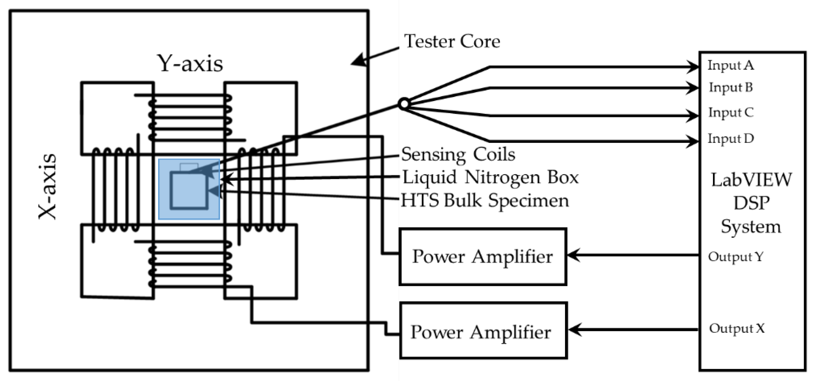
In this article, a modified SST is used to generate a purely circular magnetic field. A precisely fabricated liquid nitrogen box is installed in the middle of the taster, where a bulk sample is housed inside. Special coils are designed to sense the x and y components of B and H. Consequently, the dissipated loss is worked out using Poynting’s theorem.
3.1. HTS Bulk Sample
In this investigation, a square sample of HTS bulk is used. Such HTS bulks originate from RE-Ba-Cu-O (where RE stands for rare-earth element), such as yttrium barium copper oxide (Y-Ba-Cu-O), and are fabricated using the top-seeded melt-growth technique. These materials can trap large magnetic fields at low temperature, contrary to the traditional permanent magnets. Furthermore, the sample size and value of the critical current density can greatly improve the magnetic field strength trapped in HTS permanent magnets. These trapped field magnets are excellent candidates for developing small, light, and energy-efficient electrical machines with exceptional high-power densities, such as high-performance electrical motors and HTS magnetic levitation, because of this unique characteristic. The geometry of these materials make them the ideal candidates for our investigation. A customized sample with the dimension of 40 mm × 40 mm × 10 mm was procured to suit the tester specimen requirement.
3.2. Square Specimen Tester
A square specimen tester, as presented by Brix et al. [
30], is advantageous for detecting 2D power loss because of its flexible control mechanism, more uniform magnetic field, and greater precision than any other standard measurement device. In this study, a modified single-sheet SST [
31,
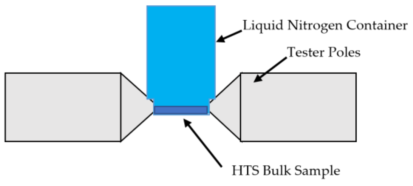
32] is used to investigate the rotating dissipative AC loss characteristics of the HTS bulk sample. The SST is comprised of yokes, which are composed of silicon steel sheets that are grain-oriented and vertically laminated. The tester features four wedge-shaped magnetic poles, thanks to the construction of the yokes’ forms. On the X-axis and Y-axis’ magnetic poles, two sets of excitation coils are linked in series to one another. Each coil has 300 turns of insulated copper wire that is 1.6 mm in diameter. A precisely fabricated liquid nitrogen box is installed in the middle of the taster to house the HTS sample that is submerged in liquid nitrogen. A square specimen of the material is positioned in the tester’s center.
Figure 1 and
Figure 2 depict the equivalent block diagram of the 2D experimental setup and the positioning of the liquid nitrogen box, respectively.
The two sets of exciting coils are then excited to create the rotating magnetic field surrounding the sample. To create rotating magnetic fields, two channel excitation signals with a 90° phase difference are produced using LabVIEW via the power amplifiers. The magnetization in the specimen is induced by the tester’s rotating magnetic field, and the induced magnetizations are then monitored along both axes by specially designed and calibrated B and H sensing coils, respectively. An FPGA-based digital processing system is used for both function generation and data acquisition.
3.3. AC Loss Measurement
In order to validate the effectiveness and performance of the SST in this experimental setup, a square sample of HTS bulk can be systematically tested under various B vectors rotating in a circular orientation. Specialized B and H coils are used in order to determine the x and y components of the flux density (Bx and By) and magnetic field strength (Hx and Hy), respectively.
Specially designed sensing coils that are positioned all over the specimen are used to measure the B and H. Using the field-metric approach, the rotating AC is then worked out by measuring the components of B and H. These measured quantities are obtained by inducing the micro-volt range’s voltage in the coils. To solve the low voltage measurement issues, both types of sensing coils are used with precision operational amplifiers.
To measure the H components, one coil is placed in the
X-axis direction and the other in the
Y-axis direction, while the B-sensing coils are looped across the center of the specimen. A 0.50 mm plastic former is twisted with 100 turns of 0.06 mm enamel-insulated copper wire to create the H-sensing coil for each axis. The induced voltage in the coils is then incorporated in the following equation [
31], which is used to obtain the components of H for each axis:
where
is the permeability of air,
is the induced voltages in the sensing coils, and
is the coil coefficients, obtained by calibrating the coils in the long solenoid method [
29].
To measure the B components, 20 turns of 0.1 mm enamel-insulated copper wire make up each coil. The induced voltage in the coils is then incorporated in the following equation, which is used to obtain the components of B for each axis:
where
is the voltage induced in the coils,
is the coefficients of each coil, which considers the number of turns and the cross-section area of the specimen [
31].
From the measured
x and
y components of the magnetic flux density and field strength, the B–H relationship can be analyzed. Moreover, these measured instantaneous values of B and H can yield additional information such as the various loss contributions, the loci of the H and B vectors, the harmonics, etc. Furthermore, power dissipation, which occurs when a rotating magnetic field is applied to a magnetic material specimen, can be measured according to Poynting’s theorem [
31]:
where
T is the time period of one magnetization process,
is the sample mass density, and
Hx,
Hy and
Bx,
By are the
x and
y components of H and B, respectively.
4. Results
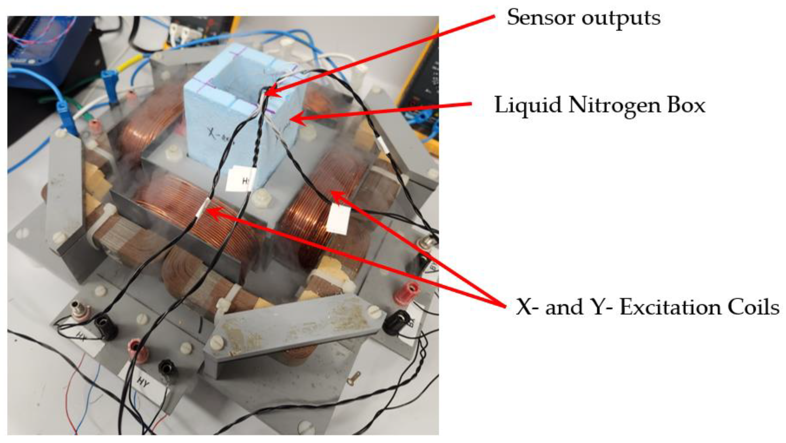
In this study, a new experimental technique has been reported to measure the AC loss in HTS material when it is subjected to rotating magnetic fields. A square HTS bulk specimen of 40 mm × 40 mm × 10 mm from Can Superconductors has been used, where the specimen is prepared with sensing coils to sense the components of B and H. The specimen is carefully installed in the specimen slot, where it is submerged in liquid nitrogen to keep it in the superconducting region. However, the liquid nitrogen level is maintained to keep the desired cryogenic state needed for maintaining the superconducting state. An image of the experimental setup is shown in
Figure 3, where gaseous nitrogen is clearly visible after expanding.
Once the setup is installed, and cryogenic state is maintained, it is ready for measurements. Furthermore, when the specimen is exposed to the external magnetic field, the loss is dissipated immediately, creating an adiabatic situation. However, in our study, the material is completely submerged in the cryogenic environment, and the level of liquid nitrogen is maintained constantly by continuous pouring into the container.
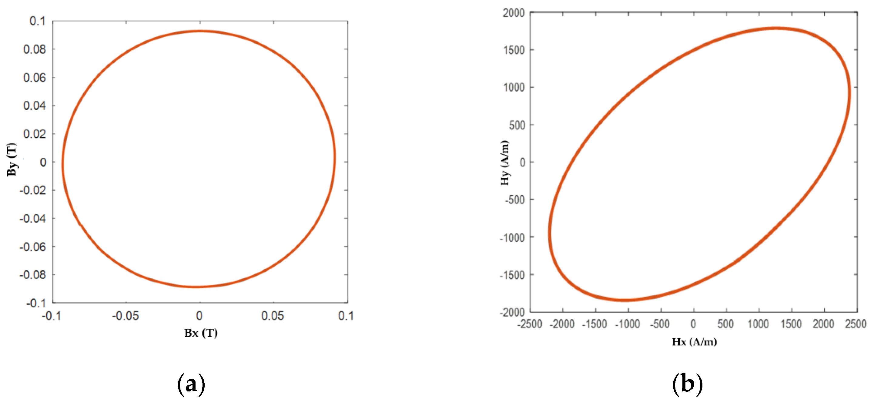
In this initial study, a purely circular rotating magnetic field was applied with various amplitudes, and the results can be obtained as described in
Section 3.2.
Figure 4 shows a sample of the controlled locus of B and the corresponding locus of H at the magnetic flux density of 90 mT at 50 Hz. It can be seen that the locus of H is not circular compared to the locus of B, as the permeability contrasts with B and H; besides, the maximum values of Hx and Hy are also not similar, as the material behaves differently, when magnetized in the x and y directions.
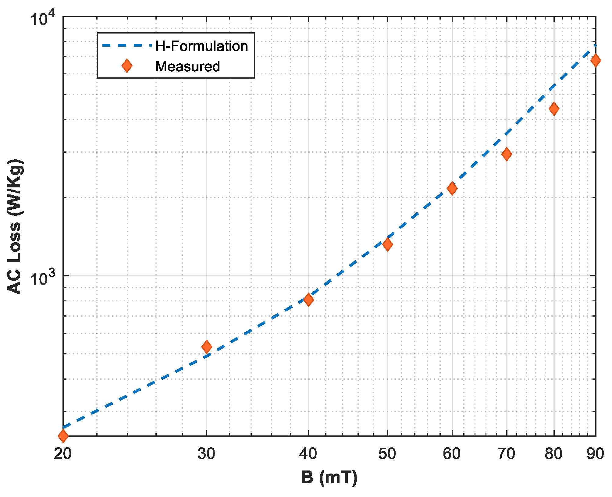
Furthermore, the loss variation is also shown in
Figure 5, where the HTS sample is subjected to various rotating flux densities up to 90 mT. The loss is also compared with the numerical modeling methods described in [
20,
21,
22,
33,
34]. H-formulation is a powerful tool based on the finite element modeling method. Readers may refer to the recently published investigations of the authors.
5. Conclusions
The AC loss measurement is, no doubt, one of the most important aspect of the HTS characterization. The existing methods about the AC loss computation only focus on the loss measurement under one-dimensional (1D) alternating magnetic fields generated by the transport current in the HTS material itself or through external excitations. However, given the limitations in the existing measurement systems, it is impossible to investigate the AC loss under exposure to rotating magnetic fields. This article presents a new experimental setup, in order to measure the AC loss in HTS material upon exposure to a rotating magnetic field. The experimental results show consistency with the modeling results. This method will be helpful in the further characterization of HTS material, especially under exposure to rotating magnetic fields, in order to design large-scale HTS applications. Moreover, in this paper, only the experimental technique is presented, considering the limitations of the existing measurement systems. Additional results and the characterization of the HTS material under rotating magnetic fields will be presented in a future study.


