Article

Performance Analysis and Optimization of a Novel Outer Rotor Field-Excited Flux-Switching Machine with Combined Semi-Closed and Open Slots Stator

1
Department of Electrical and Computer Engineering, COMSATS University Islamabad, Abbottabad 22060, Pakistan
2
Department of Electrical and Computer Engineering, King Abdulaziz University, Jeddah 21589, Saudi Arabia
3
Center of Research Excellence in Renewable Energy and Power Systems, King Abdulaziz University, Jeddah 21589, Saudi Arabia
4
The Applied College, King Abdulaziz University, Jeddah 21589, Saudi Arabia
*
Author to whom correspondence should be addressed.
Energies 2022, 15(20), 7531; https://doi.org/10.3390/en15207531
Submission received: 16 September 2022 / Revised: 5 October 2022 / Accepted: 9 October 2022 / Published: 12 October 2022

Abstract

:
Slotting effect in electric machines reduces flux per pole that effect magnetic flux density distribution in the air gap which induces harmonics in magnetic flux density causing flux pulsation, that in turn generates dominant torque pulsation in the form of cogging torque and torque ripples. To overcome the abovesaid demerits, a novel outer rotor field-excited flux-switching machine (OR-FSFSM) with a combined semi-closed and open slots stator is proposed in this study. The developed OR-FEFSM offers a high-power factor, due to the utilization of the semi-closed slot for armature coils. The open slot stator structure was chosen for the field excitation coil, which effectively suppresses leakage reluctance that causes flux pulsation. Thus, the influence of torque ripples is reduced, and the average torque is improved. In order to investigate the effectiveness of the proposed OR-FEFSM, a detailed study of stator slot and rotor pole combinations are performed. Based on simplified mathematical formulation, 12S/7P (stator slot/rotor poles), 12S/11P, 12S/13P, and 12S/17P are the most feasible combinations. Finite Element Analysis (FEA) based on comprehensive electromagnetic performance is performed on each combination, and found that 12S/13P offers the highest average torque of 4.62 Nm, whereas 3.72 Nm, 2.72Nm, and 1.68 Nm average torque is offered by 12S/17P, 12S/7P, and 12S/11P, respectively. Based on the initial analysis, 12S/13P was considered for further analysis and optimized using JMAG built-in Genetic Algorithm (GA). Moreover, thermal analysis was performed, and the proposed design was compared with the conventional design.

1. Introduction

Flux-switching machines (FSMs) are a class of synchronous machines that attract researcher interest due to their doubly salient structure, featuring both excitation sources (permanent magnet (PM) or winding) on the stator and robust rotor structure [1,2,3,4,5]. Since there are no PMs or windings on the rotor, FSM has a robust rotor structure like switched reluctance machines (SRM), making it a strong candidate in many industrial applications where high speed and rigidness are required [6,7,8]. Thus, due to the inherent feature of high torque and power density, single-phase, three-phase, and multiphase FSM topologies, such as PM excited, field excited (FE), and hybrid excited (HE), have been researched over the past few decades [9,10].
Permanent magnet flux-switching machines (PMFSMs) offer high torque density, efficiency, lower harmonic components in their back-electromotive force (back-EMF), and robust rotor structure [11,12,13]. Due to the stator’s flux-concentrating effect, PMFSM easily generates a high magnetic flux density in the air gap and therefore achieves high torque [14,15,16]. However, field weakening is a problem for these machines because their d-axis inductance is lowered due to deep magnetic saturation in the stator, limiting their constant power speed range. Additionally, the possibility of irreversible demagnetization, cost of rare earth magnets, uncontrollable flux, and PM’s low mechanical strength are all critical issues limiting PM machines to some extent. Therefore, reduced PM or no PM machines are preferred [17,18].
Hybrid excited flux-switching machines (HEFSMs) have the potential to improve power density, efficiency, and flux weakening performance [19,20,21], and overall reduce the volume of PM by adding FE coils (FEC). However, the presence of both excitation sources (PM and FEC) on the stator makes its geometry complex. To overcome the aforesaid demerits of HEFSM and PMFSM, field-excited flux-switching machines (FEFSMs) are introduced that are fully excited by windings and have more robust rotors than other types of FSM. Despite their lower efficiency, the field current regulation makes FEFSM a suitable alternative for variable speed applications [4,22].
FEFSM that utilize only field winding as a magnetic excitation are proposed in [23]. The field-weakening capabilities of this machine have been greatly enhanced due to flux regulation capability with dc excitation current that effectively reduces excitation magnetic field. However, the field windings are wound around every other stator tooth, causing the magnetic field to be radially excited and unable to be concentrated, which results in low torque density. To improve torque-power density, the authors of [23] investigated wound field-excited FSM with non-overlapped winding and segmented rotor structure. Due to the advantages of flexible flux weakening capability and short flux path, high-torque density is achieved. However, FEFSM topologies with segmented rotors suffer from mechanical constraints, and are not feasible for high-speed applications due to rotor segmentation.
The authors of [24] introduce a partitioned stator FEFSM (PS-FEFSM) with a double stator, having field and armature winding on a separate stator, so that FEC are arranged in the inner stator. In contrast, armature windings are placed in outer stators, thus increasing the torque density by 19% more than conventional FEFSM. However, manufacturing cost increases, due to the partitioned stator with two air gaps; and with metallic coupling of the rotor pieces, the cage losses increase, which can be incorporated with non-metallic sticks.
Despite the average torque improvements, the influence of the cogging torque and torque ripples are dominant in FEFSM. In this regard, the authors of [23] comparatively investigated FEFSM with and without skew rotor for torque ripple reduction. However, torque ripple is suppressed at the cost of a reduction in average torque. To further improve the torque profile, the authors of [25] examined torque characteristics of an OR-FEFSM with maximum torque control; however, this design suffers from magnetic saturation under higher currents. Moreover, dual-stator OR-FEFSM for unbalanced shaft magnetic force in [26] is effectively suppressed at 3% reduction in average torque.
To address the aforementioned problems in various state-of-the-art designs, this paper proposes a novel OR-FEFSM (as shown in Figure 1) for direct-drive embedded in-wheel systems, with an improved torque profile utilizing combined semi-closed and open stators. Furthermore, due to the elimination of mechanical gearboxes, the proposed OR-FEFSM omits maintenance costs, ultimately improving system operation efficiency. In contrast, combined semi-closed and open slots dominantly suppress torque ripple issues and improve overload capability. Therefore, this paper intends a finite element analysis (FEA)-based detailed investigation of the proposed OR-FESM with possible rotor pole combinations.
Section 2 discusses design topology and operating principles, while Section 3 investigates FEA-based performance analysis of possible rotor pole combinations. Section 4 describes the genetic algorithm. Section 5 examines the best rotor pole’s detailed FEA-based performance study. Section 6 depicts a quantitative comparison of electromagnetic performance, whereas Section 7 investigates a comparison of conventional and proposed designs. Section 8 draws a conclusion.

2. Design Topology and Operating Principles

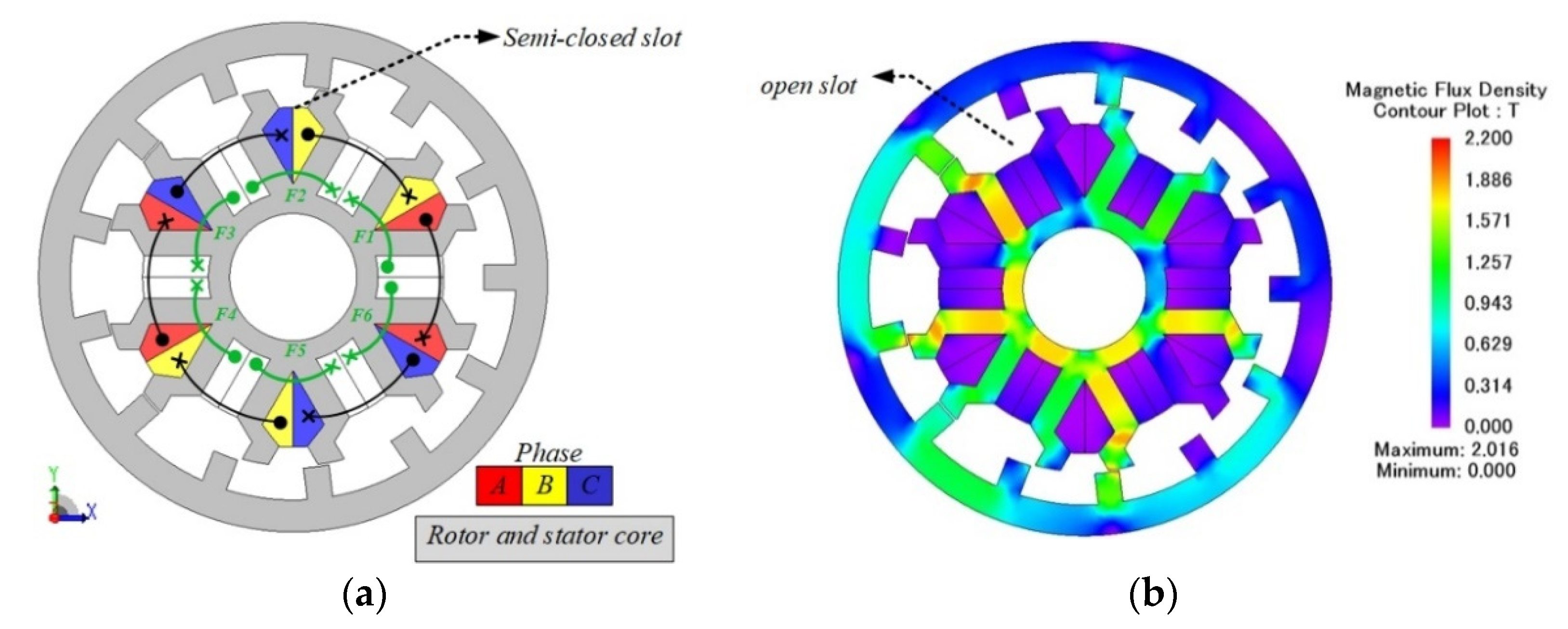
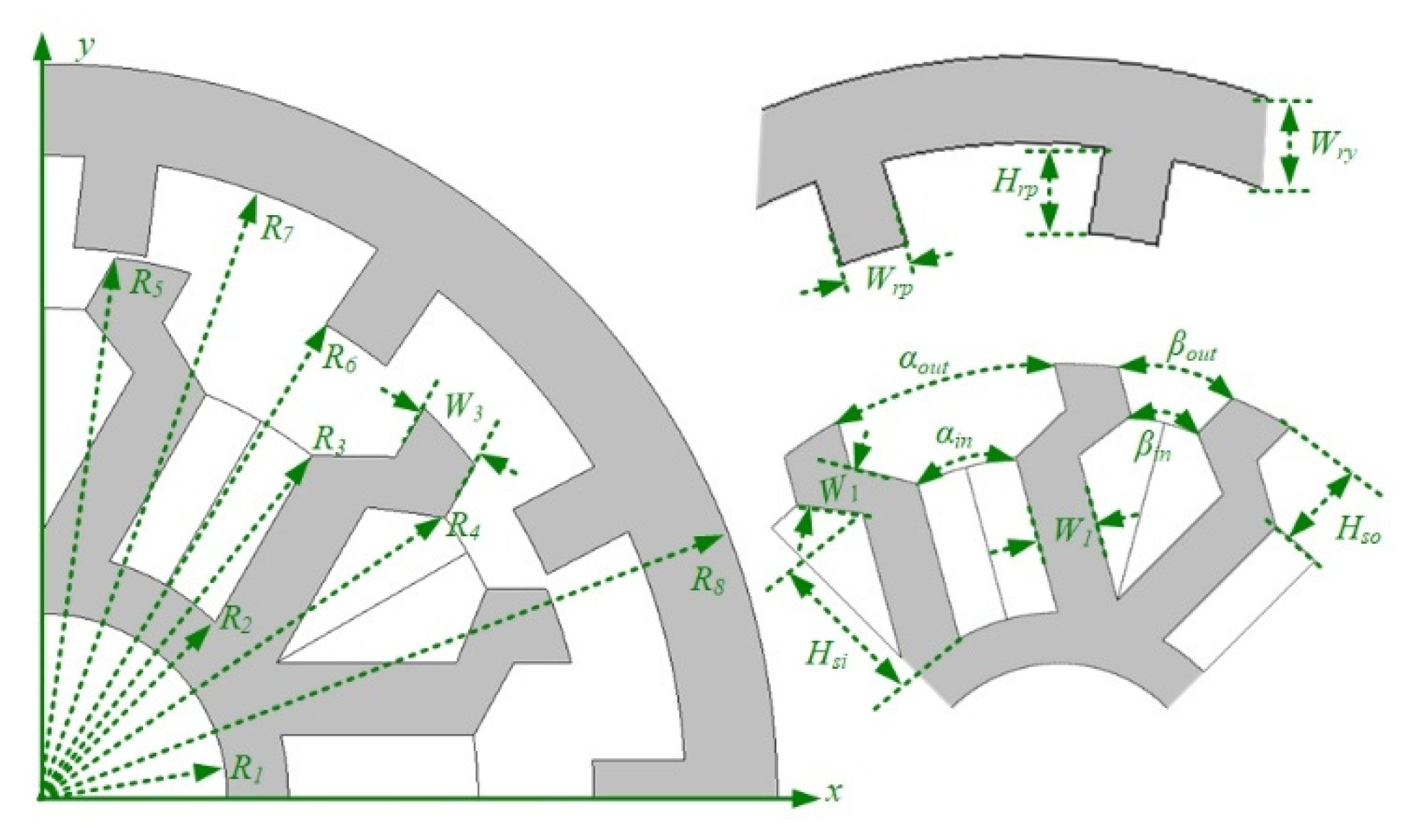
2.1. Design Topology

The proposed 12S/13P OR-FEFSM is shown in Figure 1. It consists of a salient outer rotor and an inner stator having both armature and field winding. The material used for the stator and rotor is 35H210 silicon steel, and copper is used for the winding. Geometric parameters of the proposed OR-FEFSM are shown in Figure 2 and listed in Table 1, while the simplified operating principle based on the flux-switching principle and possible rotor pole combinations are explored as follows.

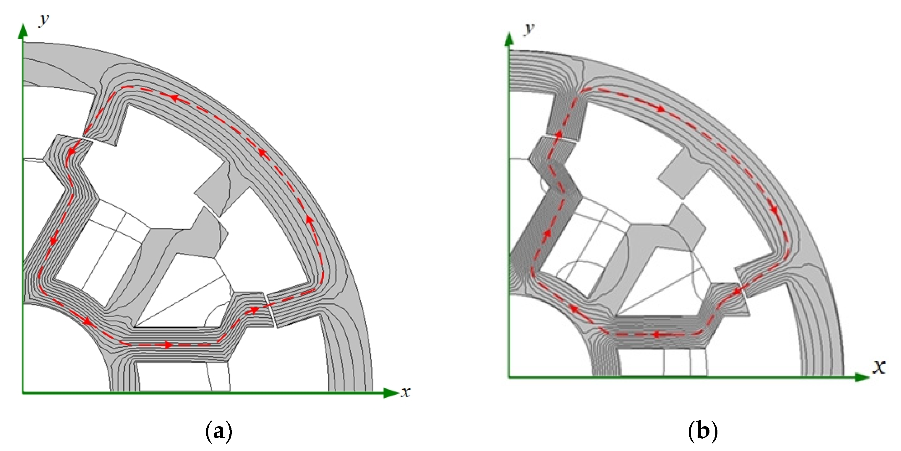
2.2. Operating Principles

The operating principle of OR-FEFSM is similar to PMFSM, and can be easily explained by the structure shown in Figure 3a,b. The upper laminated part is a rotor-like SRM, and the lower part consists of an armature winding (AW) and FEC labeled in the stator. The flux generated by the FEC flows through the path with the least reluctance. As shown in Figure 3a, when the rotor poles align with the stator teeth, around which the phase coil is wound, the flux that is linked in the coil leaves the rotor tooth and enters the coil. Similarly, as the rotor rotates further and another rotor pole aligns with the next stator tooth of the same coil, flux leaves the coil and enters the rotor tooth, maintaining the same amount of flux-linkage but reversing the polarity, as shown in Figure 3b. The coils flux linkage varies regularly as the rotor rotates, producing sinusoidal back-EMF. Torque is generated when current is appropriately provided to the coils, which drives the armature forward.

2.3. Rotor Poles Combination

Rotor pole position determines the basic principle of FEFSM due to magnetic flux linkage in armature winding that will be positive and negative, depending on the rotor position. For inner and outer rotor FEFSM, possible rotor poles combinations are computed as:
N r = N s   ( 1 ± k 2 q )
where Nr represents the number of rotor poles, N s   stator slot, K is natural number, and q is number of pairs of phases. For the proposed OR-FEFSM, the values of q and N s   are 6 and 12 , respectively, whereas feasible stator slot and rotor pole obtained are 12S/7P, 12S/11P, 12S/13P, and 12S/17P.
Furthermore, for all possible rotor poles combinations, the number of turns per phase ( N a ) and number of turns for field winding ( N e ) varies based on the armature current density ( J a   ) and field excitation current density ( J e   ) as follows:
J a = I a N a α S a        
J e = I e N e α S e
where α represent the filling factor while S a and S e represent armature and field slot area, respectively. Thus, to decide an optimal values for the aforesaid associated parameters ( J e   &   J a   ), a detailed electromagnetic performance is investigated.

3. Performance Analysis of Feasible Rotor Pole Combination

In this section, a comparative analysis of the proposed OR-FEFSM is conducted for the possible rotor pole combinations. The best design based on electromagnetic analysis will be proceeded for further study.

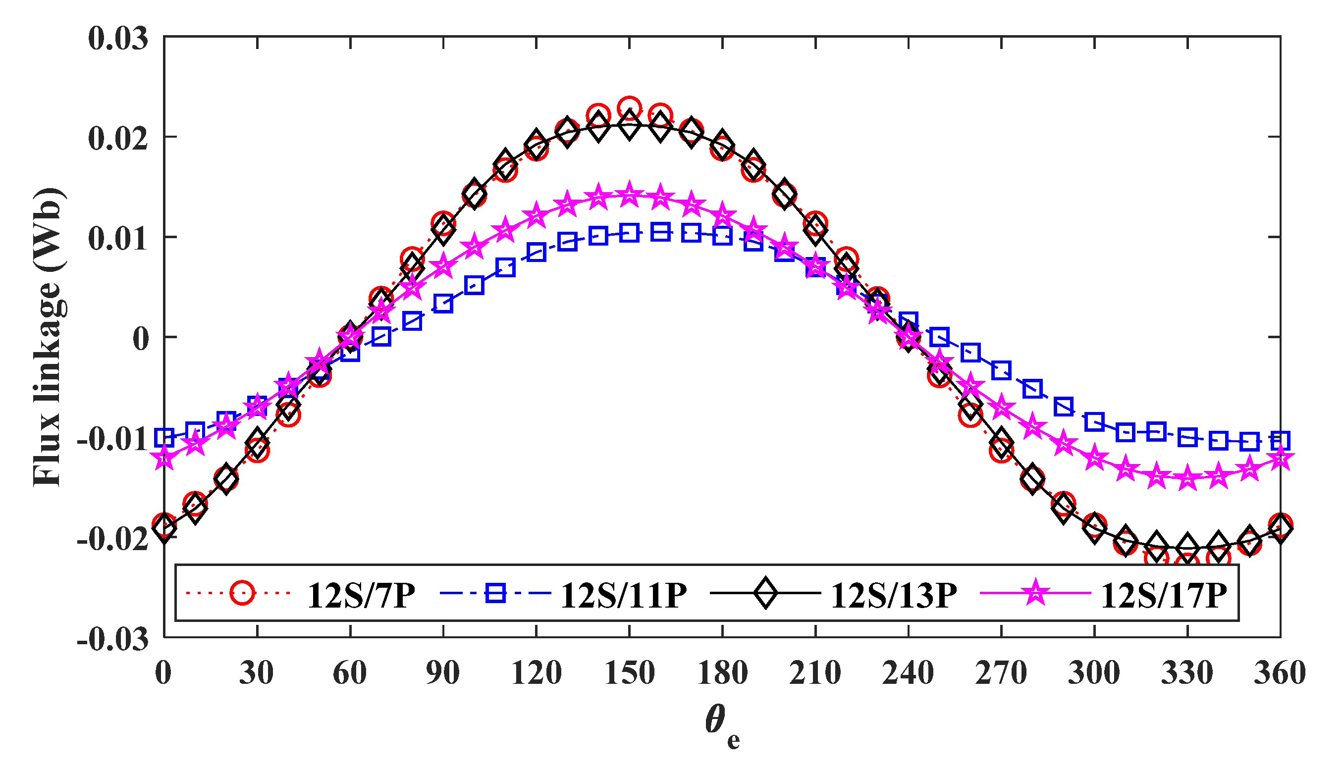
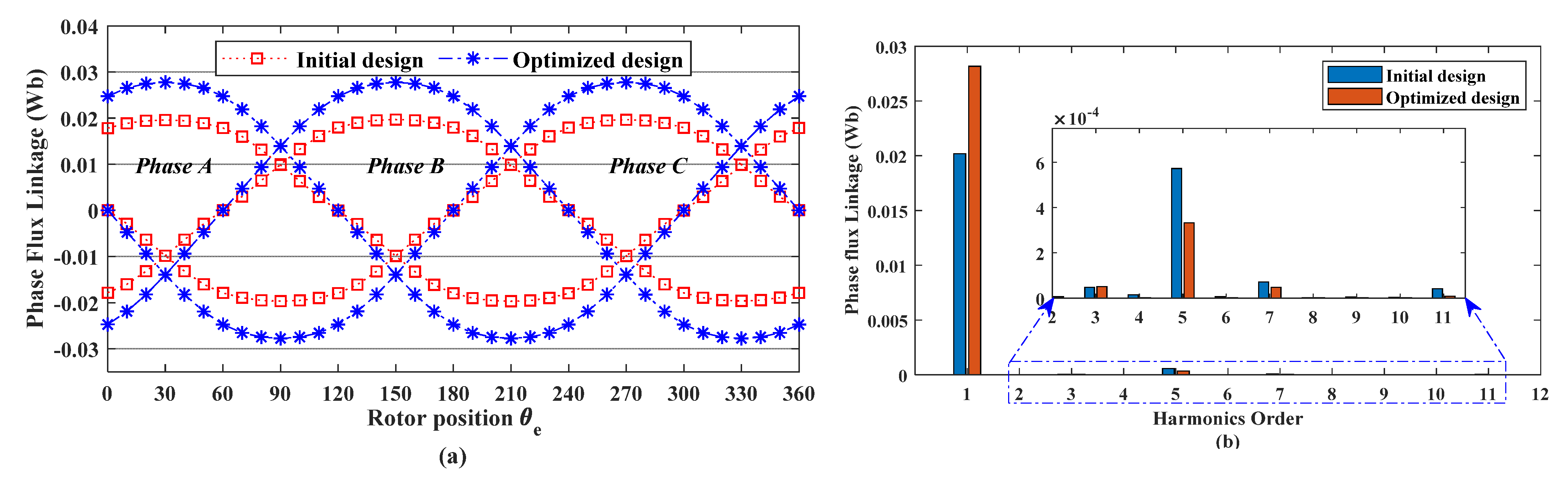
3.1. No Load Flux Linkage

Figure 4 shows the no-load flux linkage of all feasible rotor pole combinations. It is worth noting that the phase flux linkage obtained under no-load operation with J e = 15   A / mm 2 . Analysis reveals that OR-FEFSM with 12S-7P design offers the highest flux linkage of 0.020 Wb, which is 54%, 7.15%, and 37.97% higher than 11, 13, and 17 rotor poles, respectively.

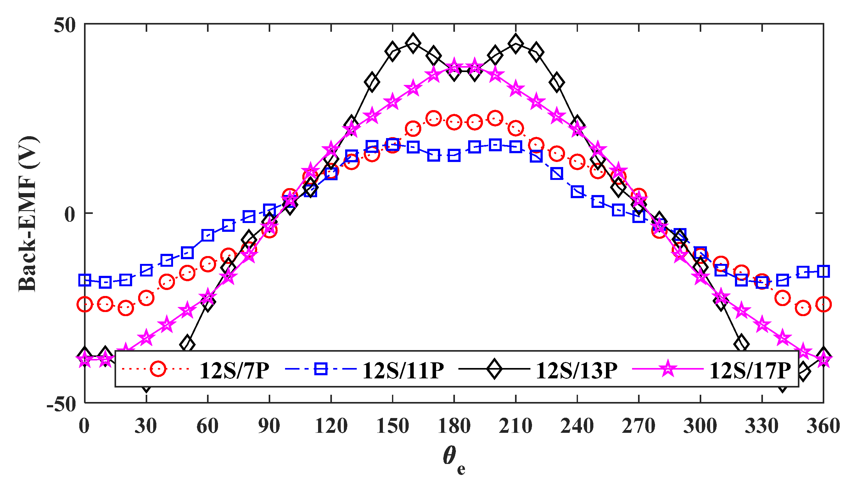
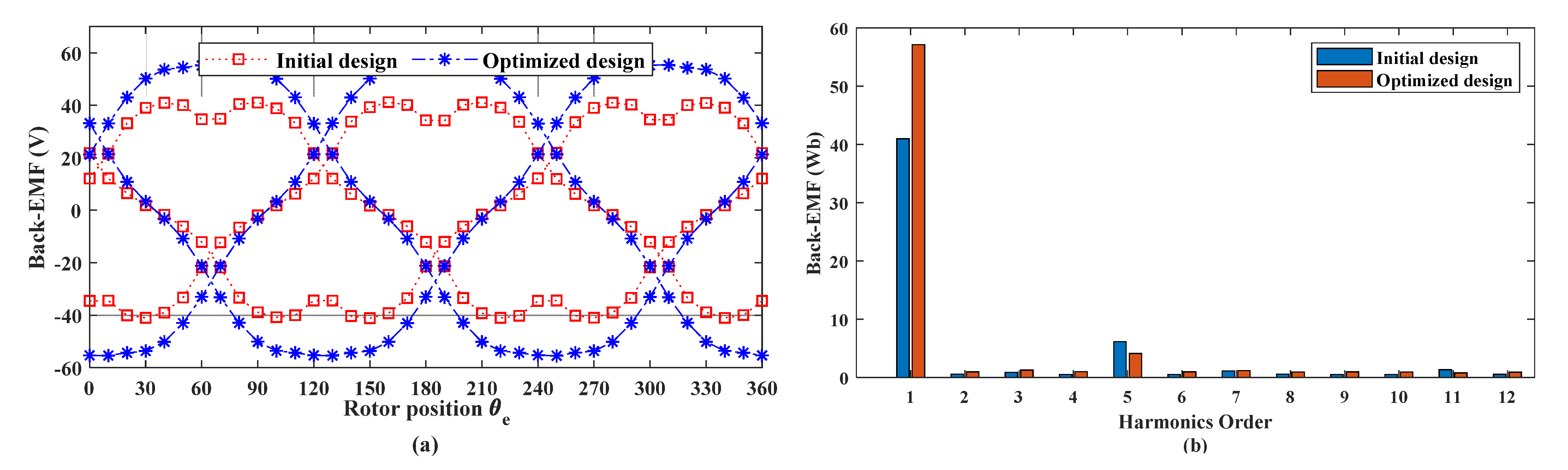
3.2. No Load Back-EMF
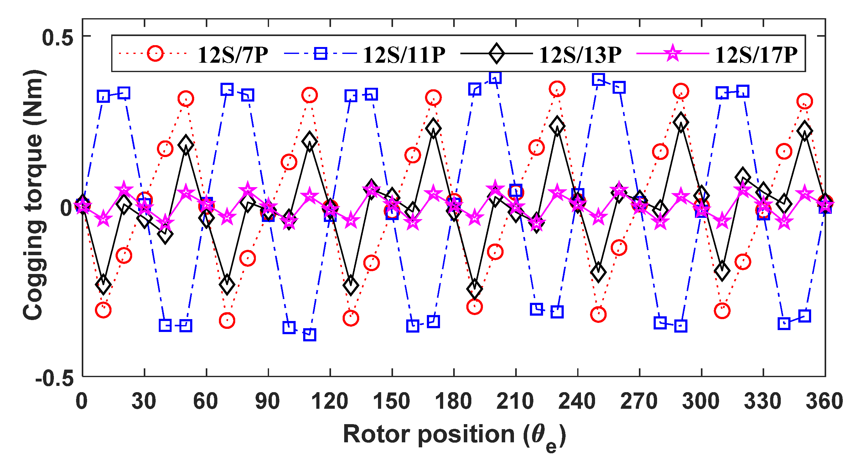
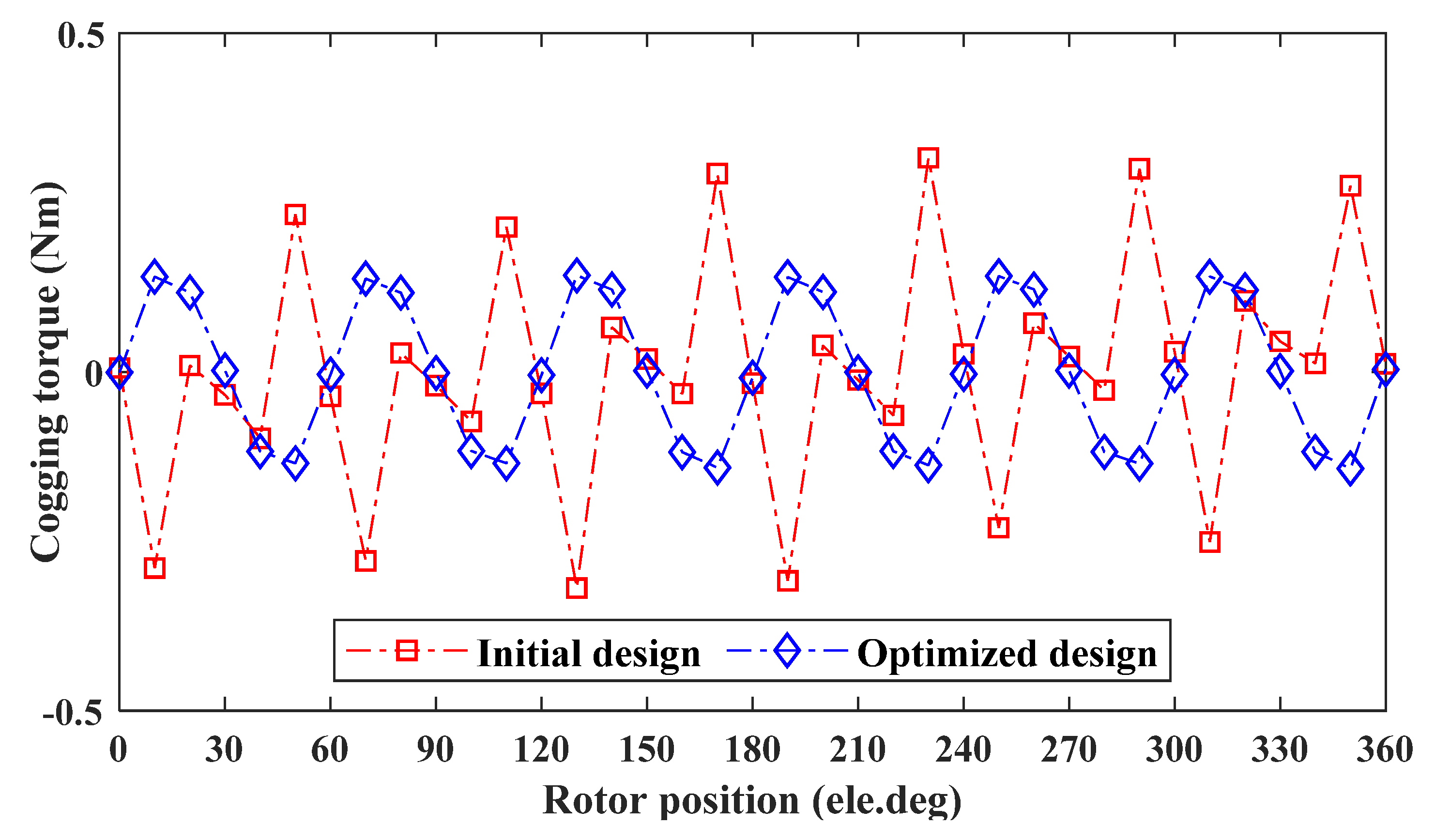
Under no-load operation, phase back-EMF for 12S/7P, 12S/11P, 12S/13P, and 12S/17P through 2D FEA is shown in Figure 5. Analysis reveals that 12S/13P shows the highest back-EMF of 44.43 V, whereas the phase back-EMF for 12S/7P, 12S/11P, and 12S/17P are 25 V, 18.13 V, and 38.63 V, respectively.

3.3. Cogging Torque

The torque obtained is cogging torque when no current is applied to the armature winding. This torque is due to slotting effects that cause acoustic noise and vibration, and is therefore undesirable. Since slotting effects change with the rotor pole number variation, the resultant cogging torque greatly vary. The cogging torques of 12S/7P, 12S/11P, 12S/13P, and 12S/17P are illustrated in Figure 6. In regard to peak magnitude, analysis reveals that 12S/17P design offers lowest cogging torque of 0.0508 Nm, whereas 12S/11P shows highest cogging torque of 0.337 Nm. Furthermore, the cogging torque profiles for 12S/13P and 12S/7P show moderate values.

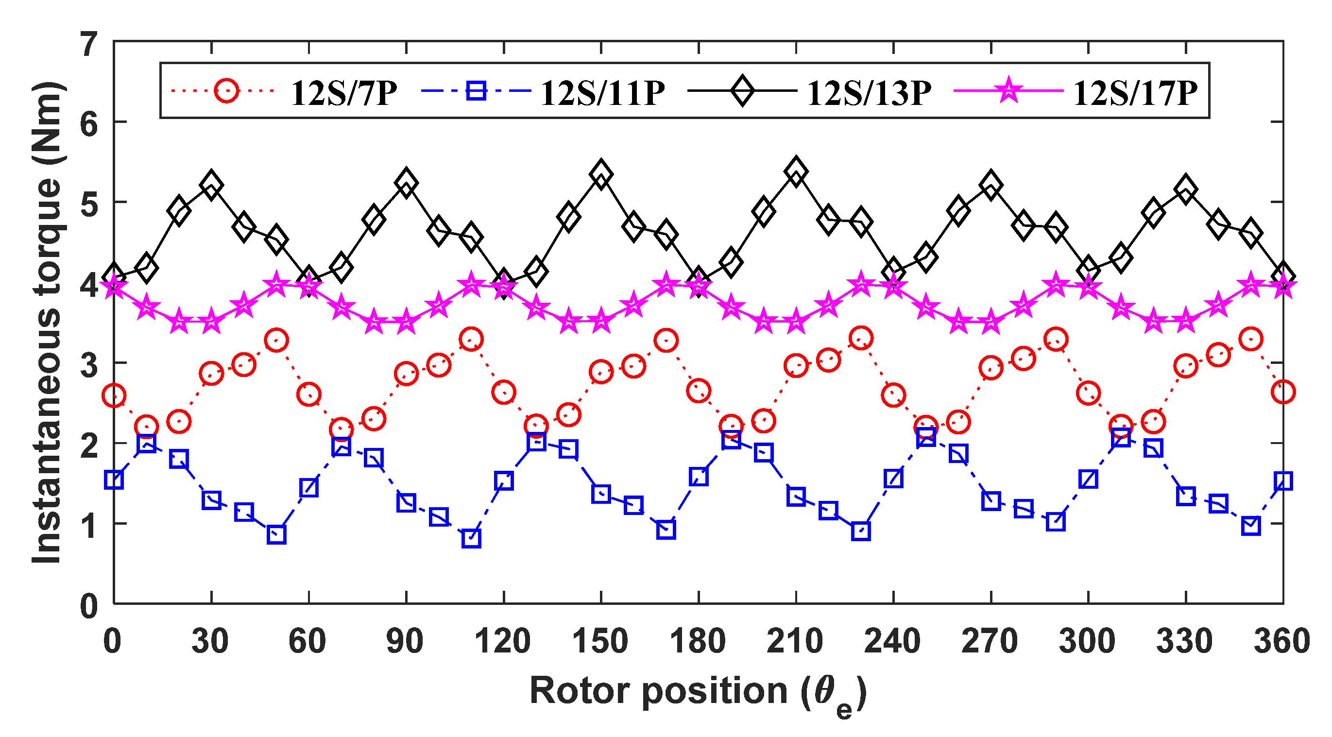
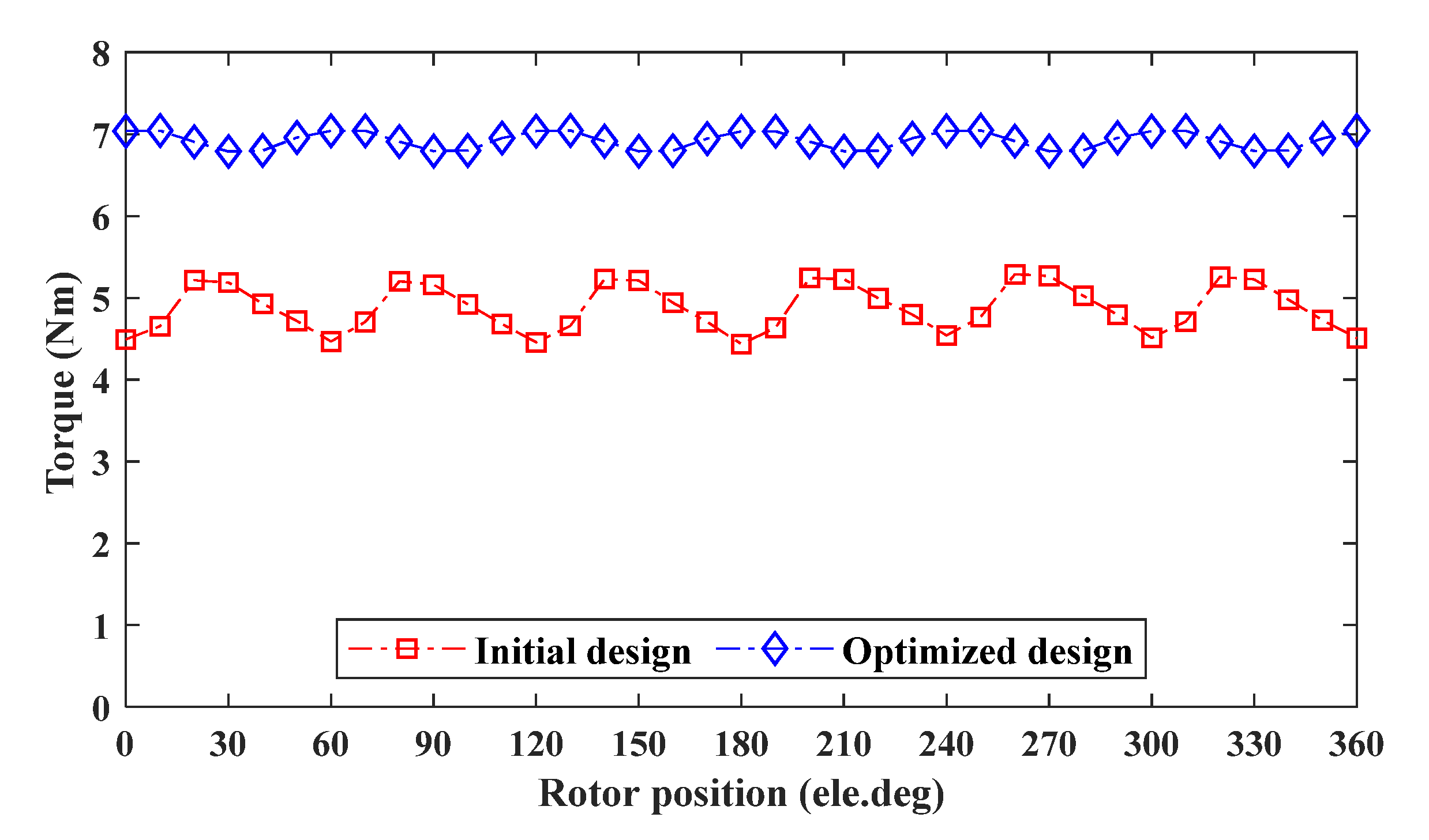
3.4. Instantenous Torque

Under loaded and rated operating conditions of J a = J e = 15   A / mm 2 and speed of 1500 rpm, instantaneous torque profile is shown in Figure 7. Comparative analysis of various rotor poles illustrates that 12S/13P offers the highest average torque ( T a v g ) of 4.62 Nm, whereas 12S/11P shows the lowest average torque of 1.68 Nm.
Table 2 represents average torque, cogging torque, torque ripples ratio, flux linkage, and back-EMF of possible rotor pole combinations. From the above analysis, it is clear that the 12S/13P combination has a more significant torque density and back-EMF at J a = J e = 15   A / mm 2 . Therefore, it is considered for further study.

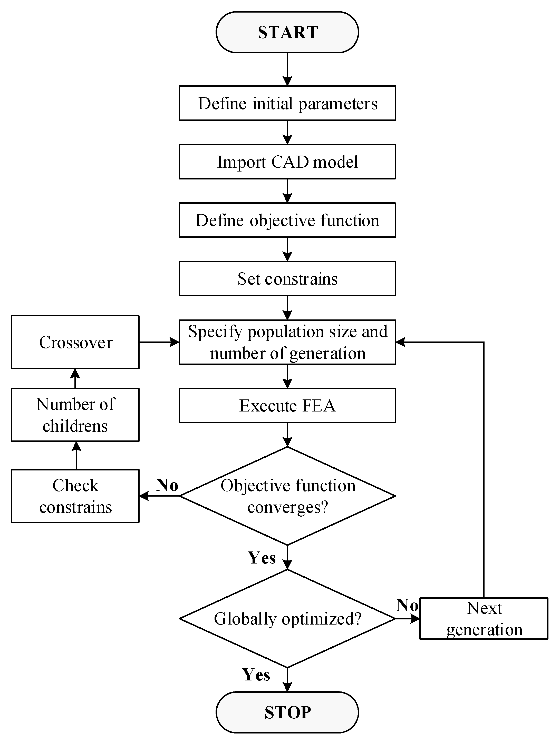
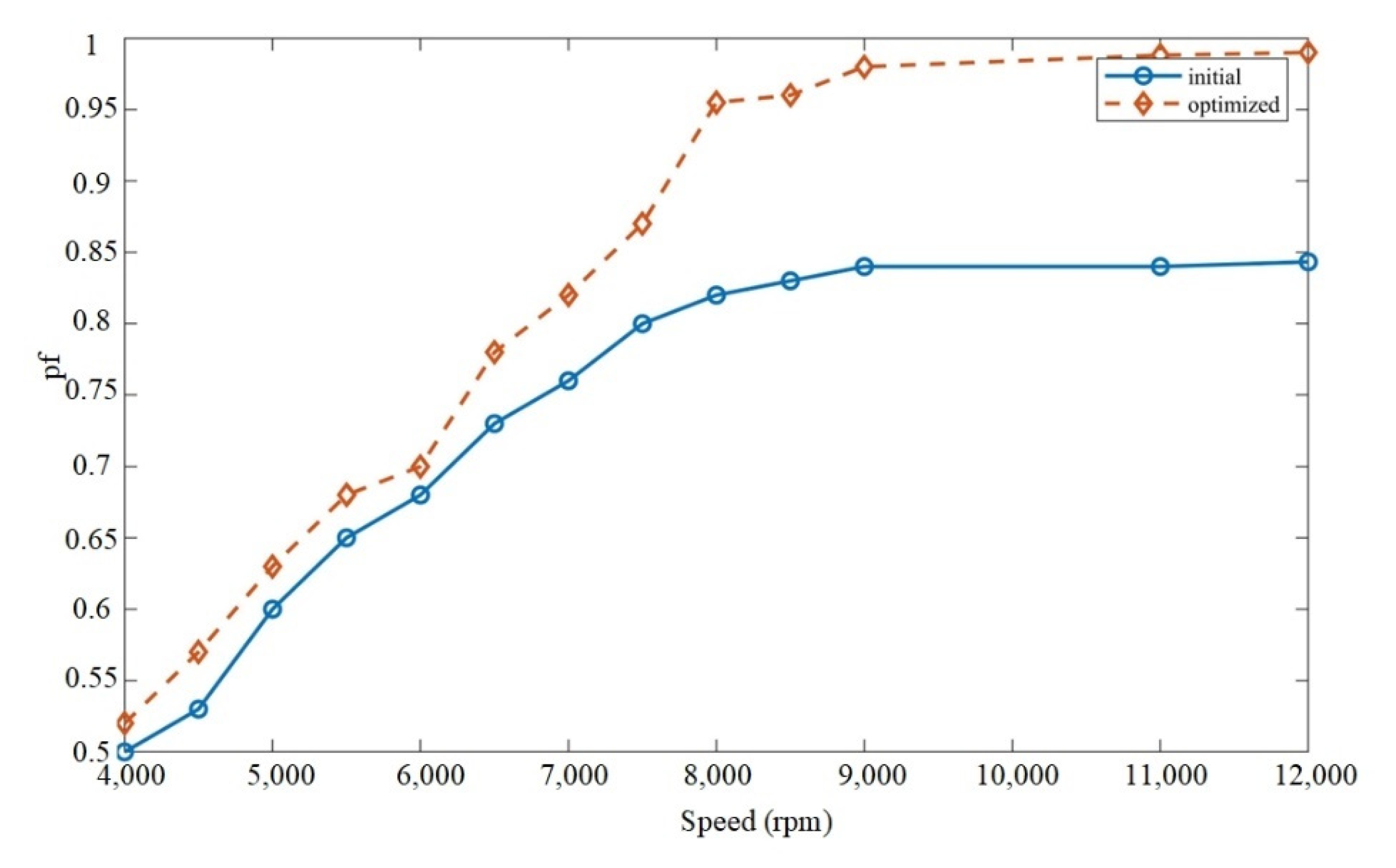
4. Genetic Optimization

In this section, optimization using genetic algorithm (GA) is used for the proposed OR-FEFSM with 12S/13P. GA is a widely common solution for optimization issues because it is particularly good at solving highly non-linear objective functions. The GA-based optimization technique is based on the evolution of the world’s animal population. It begins with a random population of variables, similar to a pool of chromosomes. A generation is the term used to describe each iteration of the algorithm. Only a few chromosomes with the most significant fitness values are carried down into the next generation, known as exceptional offspring. In addition, the technique generates new children for the next generation by simulating crossover and mutation, which are binary and unary acts on existing chromosomes, respectively. The method is repeated until one of the end conditions are met [27]. The number of generations and population size are defined to reach an optimum global value of the objective function. Figure 8 illustrates the GA workflow.
Geometry editor is used to develop the initial design, and the CAD parameters are then imported into the designer. The objective function and constraints are given below, composed of two sub-objectives. Table 3 describes the ranges and constraints of variable CAD parameters.
Objective   function = { max ( T a v g ) min ( T r i p p l e s )                            
Constraints = { T a v g > 4.62 T r i p p l e s < 0.28
Design   variables = { 3 W r y 12 2 W r p 5 3 W 1 8 3 W 2 8 3 W 3 8 12 R 1 15                          
JMAG built-in global optimization, which utilizes the GA approach, was used to optimize the geometrically significant parameters. Geometrical design variables, such as the yoke length (Wry), width of rotor tooth (Wrp), the area of the armature slot, area of the FEC slot, width of stator poles (W1, W2, W3), and the shaft radius (R1), were used to determine the optimization problem of the design. During optimization, key dimensions, such as the stator outer radius (R5), air gap, rotor outer radius (R8), stack length, rated field and armature current densities, and turns, were kept constant to maintain constant electrical and magnetic loading. In optimization settings, maximum generations were set at 14, population size at 16, number of children at 17, and stopping criteria at 10. The number of elements and nodes of each model were 12,246 and 7672, respectively. The mesh size was set to 0.5. After computing 451 case studies with GA, which took nearly 112 hours, the file size was 110 GB, the PC used was a HP core i5, 2.5 GHz, 8 GB RAM, and optimum values were obtained. Optimization results, such as torque and ripple ratio w.r.t, Wry, Wrp, W1, W2, W3, and R1, are illustrated in Figure 9 in relation to one another. Table 3 depicts the proposed design’s global optimal parameters.

5. FEA Based Electromagnetic Performance of Optimized Design

In this section, a detailed comparative analysis of optimal design is discussed.

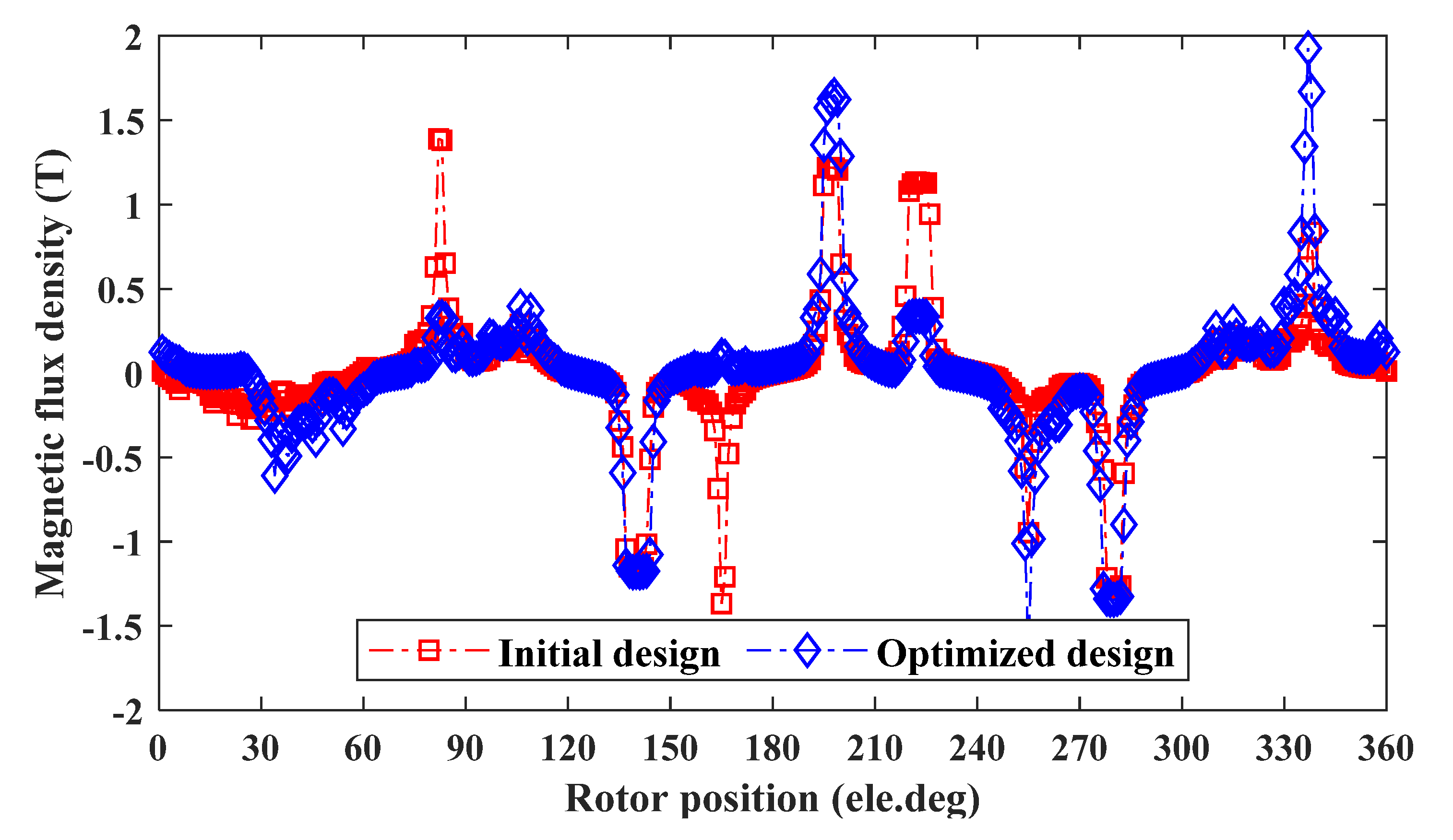
5.1. No Load Analysis
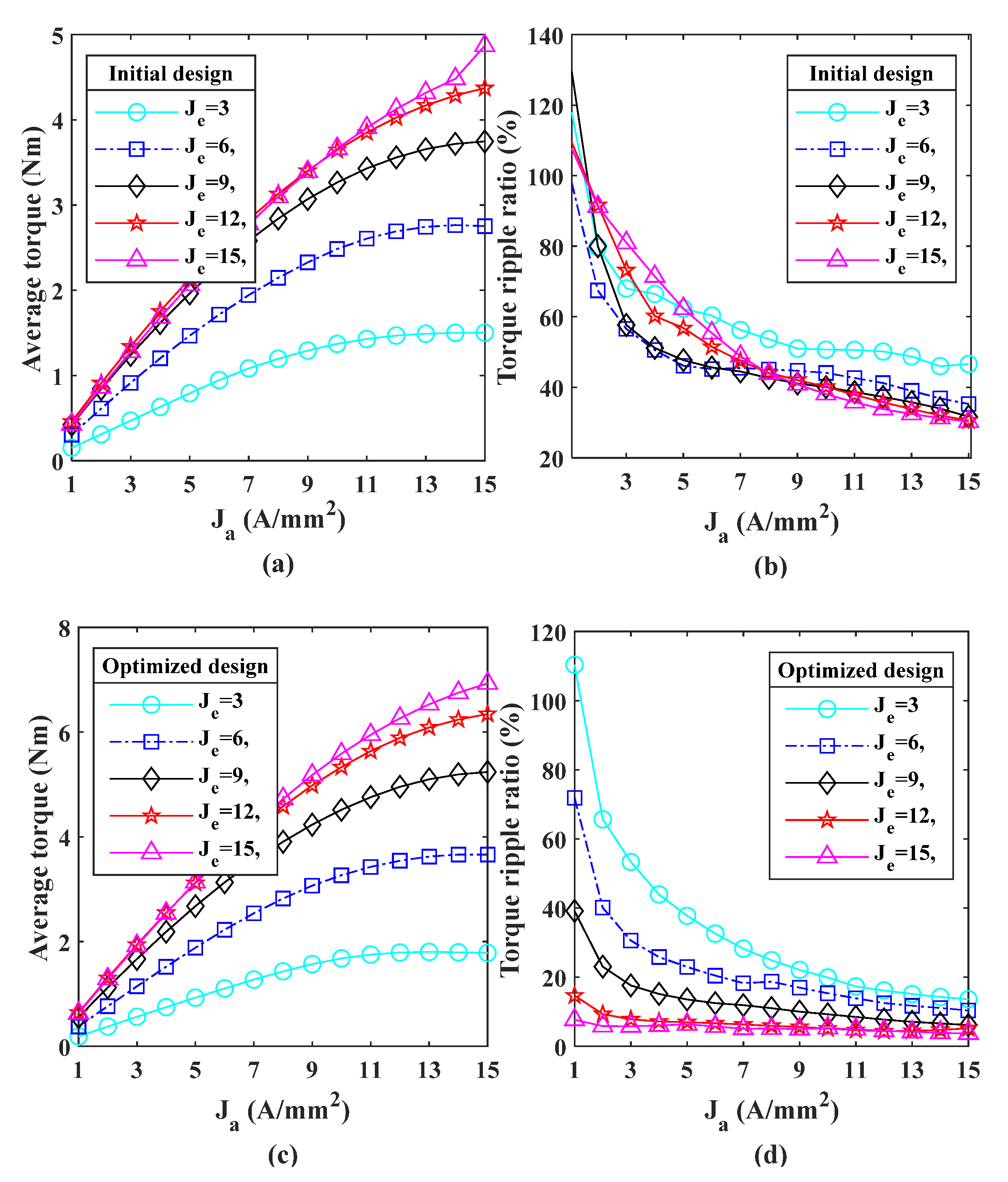
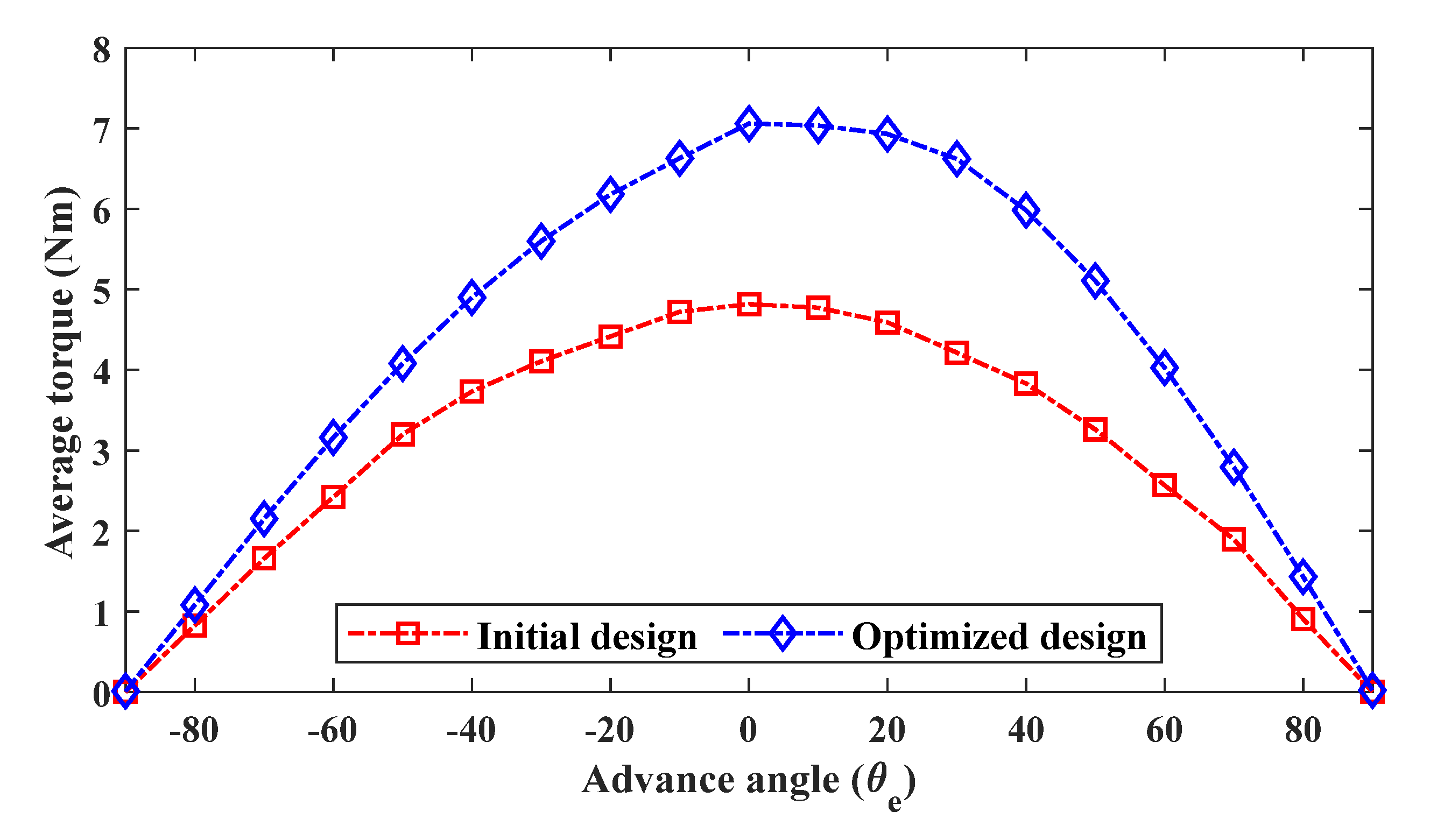
The no-load airgap flux density of 12S/13P initial and optimized design substantially fluctuates, resulting in a significant variation in the magnetic flux density over one periodic cycle, as shown in Figure 10. The peak value of airgap flux density of optimized design is 30% more than the initial. The variation of the magnetic flux density results in phase flux linkage variation. Figure 11a,b shows no load flux linkage and harmonic spectra of initial and optimized design. Analysis shows that the peak value of flux linkage is improved by 31.15% after optimization. Similarly, odd harmonics and total harmonic distortion (THD) were improved by 41.88 and 58.33%. The formula for calculating THD is shown in (4) below.
T H D = i = 2 N i 1  
where 1 is fundamental hormonic component and N is natural number
Under no-load condition, phase-back-EMF and harmonic spectra for initial and optimized design through 2D FEA is shown in Figure 12a,b. Analysis reveals that back-EMF is improved by 28%, while odd harmonics and THD is improved by 33.2% and 39.63%, respectively, after optimization. Figure 13 shows the comparison between initial and optimized cogging torque; after optimization, the cogging torque is reduced by 54.93%.

5.2. Load Analysis

Under loaded and rated operating conditions of J a = J e = 15   A / mm 2 and speed of 1500 rpm, instantaneous torque profile of 12S/13P is shown in Figure 14, which offers a 41.99% improvement in torque and 87.76% in Torque ripple ratio ( T r r ) . Furthermore, average torque profiles with torque ripples under different electric loading are illustrated in Figure 15, demonstrating the over-load capability of the proposed OR-FEFSM before and after optimization. It can be seen that under all-electric loading conditions, average torque increases, whereas the torque ripple ratio decreases. From the analysis, the torque and ripples ratios are improved by 41.99% and 87.76%, respectively, at the rated conditions. The formula for calculating torque ripple ratio is discussed in (5).
T r r = T m a x T m i n T a v g × 100
In (5) T m a x is the maximum value of torque, T m i n is the minimum value of torque, and   T a v g is the average value of torque. Figure 16 shows electromagnetic torque performance of initial and optimized design w.r.t different electrical degrees.

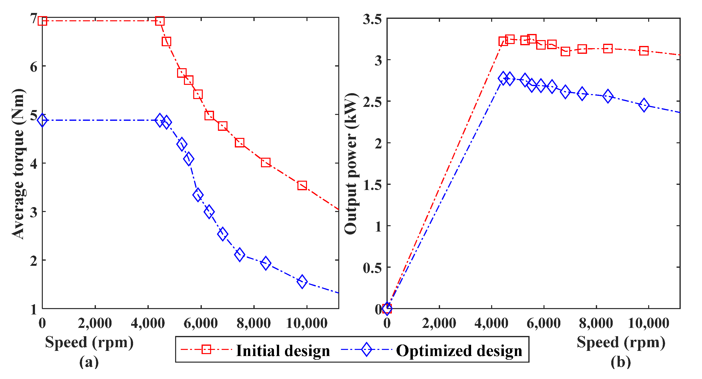
5.3. Dynamic Analysis
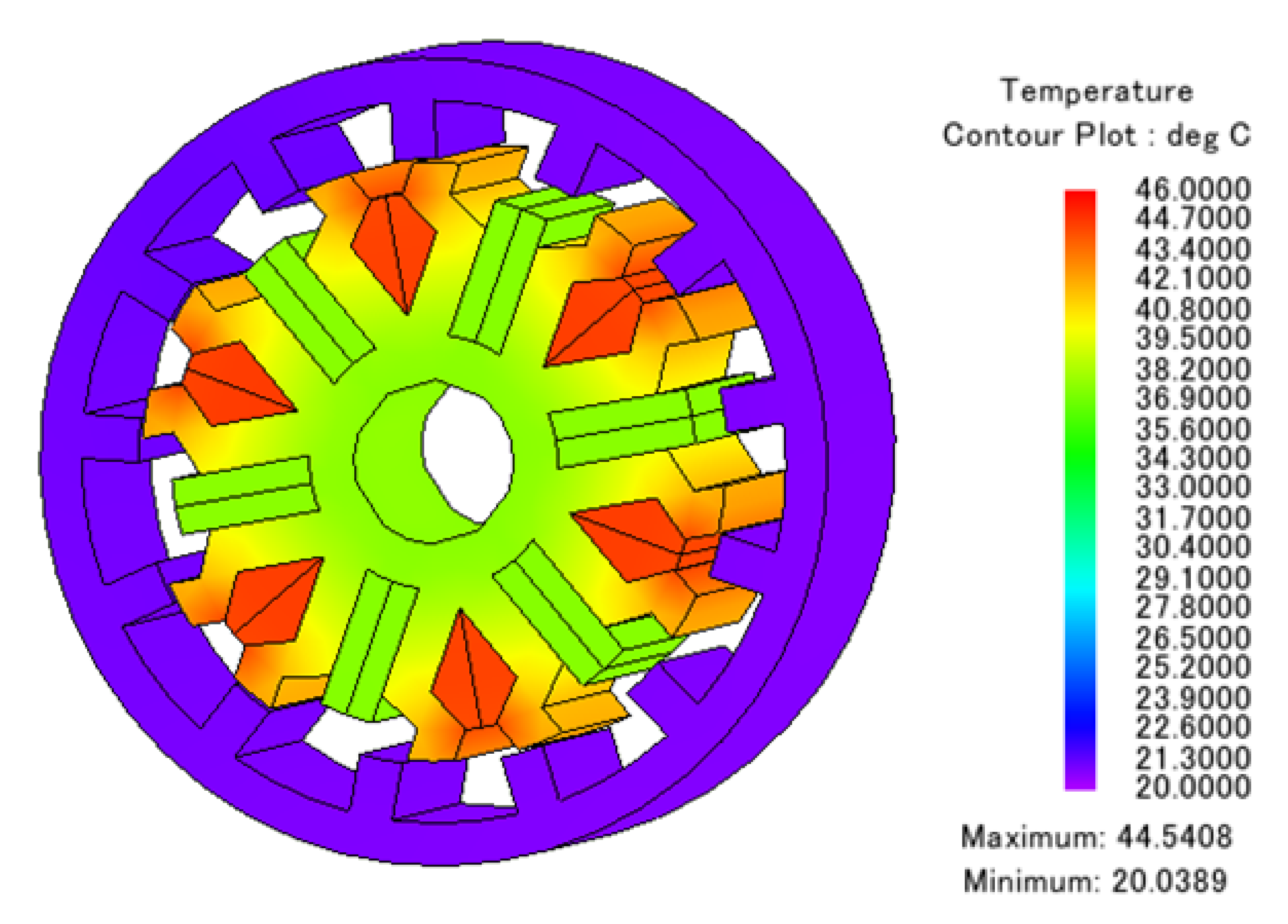
In designing an electric machine, dynamic characteristics analysis is one of the key studies that provides wide operational capability. In this regard, torque and output power, characteristics curve versus speed and power factor, give a detailed illustration of its behavior under low-speed, high-speed, constant torque, and constant output power regions, which is a prerequisite for direct-drive in-wheel-embedded systems.
The output power of the proposed machine is calculated by multiplying   T a v g with the corresponding speed. Input power is the summation of output power and total losses, including core and copper losses. Core losses can be calculated from 2D-FEA at the specified points, and (6) is used for copper losses calculation.
P C o p p e r = P C o p p e r ( A W ) + P C o p p e r ( F E C )  
where,
P C o p p e r   ( A W ) = I r m s ρ J L ( N Q ) ( 1000 )
P C o p p e r   ( F E C ) = I ρ J L ( N Q ) ( 1000 )
In (8), I represent current, ρ is resistivity, J represents current density, N   and   Q are number of turns and slot pair, respectively.
P o u t = T a v g ω
P i n p u t = P o u t +   P C o p p e r + P C o r e
Finally, efficiency is given as:
η = P o u t P i n p u t   100   %
The characteristics curve of torque and power versus speed on initial and optimized designs is depicted in Figure 17a and Figure 17b, respectively.
Similarly, the power factor can be calculated as:
P = 3 2 ( V d I q + V q I d )
Q = 3 2 ( V d I q + V q I d )
S = P 2 + Q 2
P F = c o s = P S
The power factor of initial and optimized design is shown in Figure 18.
A comparison of the initial and optimized OR-FEFSM designs is performed in order to verify and examine the performance of the GA optimization technique. Table 4 illustrates a quantitative assessment of the proposed machine.

6. Thermal Analysis

Thermal analysis is one of the most important analyses in electric machine design, as heat dissipation limits the long-term functionality of the machine. Therefore, it helps to determine the operating limits and the insulating class of the machine. The electromagnetic performance reduces when the temperature exceeds a certain permissible range, resulting in an inter-turn short circuit problem [28]. Current flow through the conductor produces heat dissipation and power loss, which raises the temperature of the whole machine. The machine has core losses in addition to the copper losses associated with the windings, which are due to the eddy current and hysteresis losses in the core. All of these losses behave as a heat source and raise temperatures. Therefore, the magnetic loss study is used to determine the losses, and thermal analysis is used to analyze the temperature distribution.
For the proposed machine, initial losses were determined using a 3D FEA followed by thermal analysis in 3D thermal studies, as 3D analysis is more precise than 2D analysis. To calculate the temperature distribution of the complete machine, the 3D loss study is combined with the 3D heat study. The 3D thermal study reveals that the stator temperature significantly rises due to the presence of all excitation sources on the stator; however, the temperature of the rotor minimally rises, as the proposed machine has a salient rotor. Figure 19 depicts a contour plot of the temperature distribution. In the stator, the temperature distribution in the windings reaches a maximum value of 46 °C. At the rotor, the highest temperature observed is 24 °C degrees.

7. Comparison of Proposed and Conventional Design

In this section, a detailed comparison of the conventional and proposed design is performed. For fair comparison with [23], the proposed model is redesigned and optimized under the same outer dimensions, stack length, current density, and air gap length. The average torque of scaled 12S/13P design is 47.95 Nm which is 36.6%, 57.1%, 48.77%, and 96.52% more than the conventional straight WFSM, skewed WFSM, 12S/8P SRM, and 12S/10P SRM, respectively. Based on the key performance matrix listed in Table 5, without any influence on efficiency, it is clear that the proposed design offers 9.4%, 65.8%, and 63.7% less ripples than the conventional straight WFSM, 12S/8P SRM, and 12S/10P SRM, respectively. Furthermore, individual machine part weight and overall weight of the proposed machine are the lowest, resulting in a better torque density than the aforementioned state-of-the-art model.

8. Conclusions

This paper proposed a novel outer rotor field-excited flux-switching machine with a combined semi-closed and open slots stator to improve power factor and torque profile. Semi-closed slots utilization improves power factor, whereas open slots suppress slot leakages that effectively suppress leakage reluctance that causes flux pulsation, improving torque ripples, and mean torque. The effectiveness of the proposed OR- FEFSM was investigated through FEA with different stator slot and rotor pole combinations. Initial FEA-based comprehensive electromagnetic performance reveals that 12S/13P offers the highest average torque of 4.62 Nm, which was considered for further study and optimized through GA optimization. The maximum output power obtained is 3.22 kW with an efficiency of 87.7%. Finally, the proposed design was compared with the state-of-the-art model, and the results showed there was significant improvement in average torque, torque ripples, weight of machine, and torque density.

Author Contributions

Conceptualization, S.A., W.U. and F.K.; methodology, S.A. and B.U.; software, S.A. and B.U.; validation, S.A. and W.U.; resources, F.K., A.H.M. and A.A.A.; formal analysis, B.U., A.H.M. and A.A.A.; original draft preparation, S.A. and W.U.; visualization, B.U.; review and editing, B.U. and F.K.; supervision, F.K.; project administration, F.K., A.H.M. and A.A.A.; funding acquisition, A.H.M., A.A.A. All authors have read and agreed to the published version of the manuscript.

Funding

This research received no external funding.

Conflicts of Interest

The authors declare no conflict of interest.

References

  1. Ullah, W.; Khan, F.; Sulaiman, E.; Umair, M.; Ullah, N.; Khan, B. Analytical validation of novel consequent pole E-core stator permanent magnet flux switching machine. IET Electr. Power Appl. 2020, 14, 789–796. [Google Scholar] [CrossRef]
  2. Jiang, W.; Huang, W.; Lin, X.; Zhao, Y.; Zhu, S. Analysis of Rotor Poles and Armature Winding Configurations Combinations of Wound Field Flux Switching Machines. IEEE Trans. Ind. Electron. 2021, 68, 7838–7849. [Google Scholar] [CrossRef]
  3. Jiang, W.; Huang, W.; Lin, X.; Zhao, Y.; Wu, X.; Zhao, Y.; Dong, D.; Jiang, X. A Novel Stator Wound Field Flux Switching Machine with the Combination of Overlapping Armature Winding and Asymmetric Stator Poles. IEEE Trans. Ind. Electron. 2022, 69, 2737–2748. [Google Scholar] [CrossRef]
  4. Zulu, A.; Mecrow, B.; Armstrong, M. A Wound-Field Three-Phase Flux-Switching Synchronous Motor with All Excitation Sources on the Stator. IEEE Trans. Ind. Appl. 2010, 46, 2363–2371. [Google Scholar] [CrossRef]
  5. Tang, Y.; Paulides, J.; Motoasca, T.; Lomonova, E. Flux-Switching Machine with DC Excitation. IEEE Trans. Magn. 2012, 48, 3583–3586. [Google Scholar] [CrossRef]
  6. Wu, Z.; Zhu, Z.; Wang, C. Reduction of On-Load DC Winding-Induced Voltage in Partitioned Stator Wound Field Switched Flux Machines by Dual Three-Phase Armature Winding. IEEE Trans. Ind. Electron. 2022, 69, 5409–5420. [Google Scholar] [CrossRef]
  7. Ullah, W.; Khan, F.; Hussain, S. A Comparative Study of Dual Stator with Novel Dual Rotor Permanent Magnet Flux Switching Generator for Counter Rotating Wind Turbine Applications. IEEE Access 2022, 10, 8243–8261. [Google Scholar] [CrossRef]
  8. Tang, Y.; Motoasca, E.; Paulides, J.; Lomonova, E. Comparison of flux-switching machines and permanent magnet synchronous machines in an in-wheel traction application. COMPEL-Int. J. Comput. Math. Electr. Electron. Eng. 2012, 32, 153–165. [Google Scholar] [CrossRef]
  9. Othman, S.; Ahmad, M.; Rahim, J.; Bahrim, F.; Sulaiman, E. Design Improvement of Three Phase 12Slot-14Pole Outer Rotor Field Excitation Flux Switching Motor. Int. J. Power Electron. Drive Syst. (IJPEDS) 2017, 8, 239. [Google Scholar] [CrossRef] [Green Version]
  10. Shen, Y.; Hu, P.; Jin, S.; Wei, Y.; Lan, R.; Zhuang, S.; Zhu, H.; Cheng, S.; Chen, J.; Wang, D.; et al. Design of Novel Shaftless Pump-Jet Propulsor for Multi-Purpose Long-Range and High-Speed Autonomous Underwater Vehicle. IEEE Trans. Magn. 2016, 52, 1–4. [Google Scholar] [CrossRef]
  11. Su, P.; Hua, W.; Wu, Z.; Chen, Z.; Zhang, G.; Cheng, M. Comprehensive Comparison of Rotor Permanent Magnet and Stator Permanent Magnet Flux-Switching Machines. IEEE Trans. Ind. Electron. 2019, 66, 5862–5871. [Google Scholar] [CrossRef]
  12. Hua, W.; Cheng, M.; Zhu, Z.; Howe, D. Analysis and Optimization of Back EMF Waveform of a Flux-Switching Permanent Magnet Motor. IEEE Trans. Energy Convers. 2008, 23, 727–733. [Google Scholar] [CrossRef]
  13. Du, Y.; Zhang, C.; Zhu, X.; Xiao, F.; Sun, Y.; Zuo, Y.; Quan, L. Principle and analysis of doubly salient PM motor with Π-shaped stator iron core segments. IEEE Trans. Ind. Electron. 2018, 66, 1962–1972. [Google Scholar] [CrossRef]
  14. Ullah, W.; Khan, F.; Hussain, S. A Novel Dual Rotor Permanent Magnet Flux Switching Generator for Counter Rotating Wind Turbine Applications. IEEE Access 2022, 10, 16456–16467. [Google Scholar] [CrossRef]
  15. Chau, K.; Chan, C.C.; Liu, C. Overview of permanent-magnet brushless drives for electric and hybrid electric vehicles. IEEE Trans. Ind. Electron. 2008, 55, 2246–2257. [Google Scholar] [CrossRef] [Green Version]
  16. Du, Z.S.; Lipo, T.A. Efficient utilization of rare earth permanent-magnet materials and torque ripple reduction in interior permanent-magnet machines. IEEE Trans. Ind. Appl. 2017, 53, 3485–3495. [Google Scholar] [CrossRef]
  17. Dorrell, D.; Parsa, L.; Boldea, I. Automotive Electric Motors, Generators, and Actuator Drive Systems with Reduced or No Permanent Magnets and Innovative Design Concepts. IEEE Trans. Ind. Electron. 2014, 61, 5693–5695. [Google Scholar] [CrossRef]
  18. Boldea, I.; Tutelea, L.N.; Parsa, L.; Dorrell, D. Automotive Electric Propulsion Systems with Reduced or No Permanent Magnets: An Overview. IEEE Trans. Ind. Electron. 2014, 61, 5696–5711. [Google Scholar] [CrossRef]
  19. Yang, G.; Lin, M.; Li, N.; Tan, G.; Zhang, B. Flux-Weakening Control Combined with Magnetization State Manipulation of Hybrid Permanent Magnet Axial Field Flux-Switching Memory Machine. IEEE Trans. Energy Convers. 2018, 33, 2210–2219. [Google Scholar] [CrossRef]
  20. Wardach, M.; Palka, R.; Paplicki, P.; Prajzendanc, P.; Zarebski, T. Modern Hybrid Excited Electric Machines. Energies 2020, 13, 5910. [Google Scholar] [CrossRef]
  21. Zhang, G.; Hua, W.; Cheng, M.; Liao, J.; Wang, K.; Zhang, J. Investigation of an improved hybrid-excitation flux-switching brushless machine for HEV/EV applications. IEEE Trans. Ind. Appl. 2015, 51, 3791–3799. [Google Scholar] [CrossRef]
  22. Pollock, C.; Pollock, H.; Barron, R.; Coles, J.R.; Moule, D.; Court, A.; Sutton, R. Flux-switching motors for automotive applications. IEEE Trans. Ind. Appl. 2006, 42, 1177–1184. [Google Scholar] [CrossRef]
  23. Zhao, G.; Hua, W.; Qi, J. Comparative Study of Wound-Field Flux-Switching Machines and Switched Reluctance Machines. IEEE Trans. Ind. Appl. 2019, 55, 2581–2591. [Google Scholar] [CrossRef]
  24. Zhu, Z.Q.; Wu, Z.Z.; Evans, D.J.; Chu, W.Q. A Wound Field Switched Flux Machine with Field and Armature Windings Separately Wound in Double Stators. IEEE Trans. Energy Convers. 2015, 30, 772–783. [Google Scholar] [CrossRef]
  25. Yang, S.; Zhang, J.; Jiang, J. Modeling Torque Characteristics and Maximum Torque Control of a Three-Phase, DC-Excited Flux-Switching Machine. IEEE Trans. Magn. 2016, 52, 1–4. [Google Scholar] [CrossRef]
  26. Nguyen, H.Q.; Jiang, J.Y.; Yang, S.M. Design of a wound-field flux switching machine with dual-stator to reduce unbalanced shaft magnetic force. J. Chin. Inst. Eng. 2017, 40, 441–448. [Google Scholar] [CrossRef]
  27. Parappagoudar, M.B.; Pratihar, D.K.; Datta, G.L. Forward and reverse mappings in green sand mould system using neural networks. Appl. Soft Comput. 2008, 8, 239–260. [Google Scholar] [CrossRef]
  28. Zhao, J.; Guan, X.; Li, C.; Mou, Q.; Chen, Z. Comprehensive evaluation of inter-turn short circuit faults in pmsm used for electric vehicles. IEEE Trans. Intell. Transp. Syst. 2020, 22, 611–621. [Google Scholar] [CrossRef]
Figure 1. Proposed OR-FEFSM (a) cross-sectional view and (b) magnetic flux density map.
Energies 15 07531 g001
Figure 2. Depicted design parameters of proposed OR-FEFSM.
Energies 15 07531 g002
Figure 3. Operating principle of OR-FEFSM (a) positive maximum flux and (b) negative maximum flux.
Energies 15 07531 g003
Figure 4. No-load operation flux linkages of all feasible combinations.
Energies 15 07531 g004
Figure 5. No-load operation phase back-EMF.
Energies 15 07531 g005
Figure 6. Variation of cogging torque profile.
Energies 15 07531 g006
Figure 7. Instantaneous torque profile with rotor pole number.
Energies 15 07531 g007
Figure 8. Flow chart of Genetic Optimization.
Energies 15 07531 g008
Figure 9. Torque and ripples ratio w.r.t optimization parameters (a) R1 (b) Wry (c) W1 (d) W2 (e) W3 (f) Wr.
Energies 15 07531 g009
Figure 10. Variation of the magnetic flux density over one periodic cycle.
Energies 15 07531 g010
Figure 11. Initial and optimized design phase flux linkage (a) waveform and (b) harmonic spectra.
Energies 15 07531 g011
Figure 12. Initial and optimized design back-EMF (a) waveform and (b) harmonic spectra.
Energies 15 07531 g012
Figure 13. Cogging torque analysis of initial and optimized design.
Energies 15 07531 g013
Figure 14. Instantaneous toque profile of initial and optimized design.
Energies 15 07531 g014
Figure 15. Overload capability of proposed design before and after optimization. (a) Torque w.r.t Ja and Je before optimization; (b) ripples w.r.t Ja and Je before optimization; (c) torque w.r.t Ja and Je after optimization; and (d) ripples w.r.t Ja and Je after optimization.
Energies 15 07531 g015
Figure 16. Torque w.r.t different electrical degrees before and after optimization.
Energies 15 07531 g016
Figure 17. (a) Torque vs. speed curve; (b) power vs. speed curve.
Energies 15 07531 g017
Figure 18. Power factor of initial and optimized design w.r.t different speed.
Energies 15 07531 g018
Figure 19. Thermal analysis of the proposed OR-FEFSM.
Energies 15 07531 g019
Table 1. Design parameter of proposed OR-FEFSM.
SymbolValue (unit)SymbolValue (unit)
R115 mm W r y 7.5 mm
R220 mm W r p 6 mm
R335.5 mm H r p 7.5 mm
R440 mm r o u t 22 mm
R544.5 mm α i n 10 mm
R645 mm W s p 6 mm
R752.5 mm H s i 15.5 mm
R860 mm H s o 9 mm
βin6.76 mm β o u t 11.67 mm
W16 mmW26 mm
W36 mmStack length45 mm
Table 2. Quantitative performance of the OR-FEFSM with various rotor pole numbers at J a = J e = 15   A / mm 2 .
12S/7P12S/11P12S/13P12S/17P
Average Torque (Nm)2.721.684.623.72
Cogging Torque P-P (Nm)0.3440.3770.2460.0508
Torque ripples (%)32163112
Flux Linkage (Wb)0.0228160.0104810.0211850.014152
Back-EMF (V)25.0618.1344.8438.64
Table 3. Variables for Genetic Optimization.
ParametersInitial (mm)Boundary ConditionsOptimized (mm)
W r y 7.5 3 W r y 12 6.3505
W r p 3 1 W r p 5 3.3055
W16 3 W 1 8 7.97017
W26 3 W 2 8 5.9480
W36 3 W 3 8 6.8116
Table 4. Performance comparison of initial and optimized design.
ParametersInitial ValueOptimized ValueImprovement
Torque   ( Nm ) 4.877 6.925 41.99 %
Torque Ripples (%) 0.30 0.037 87.76 %
Flux   linkage   ( Wb ) 0.021 0.0276 23.91 %
Airgap   flux   density   ( T ) 1.3886 1.9276 27.94 %
Back - emf   peak ( V ) 41.07 55.362 25.91 %
Cogging   torque ( Nm ) 0.3160 0.142454.93%
Odd harmonics in flux (Wb) 0.000573 0.000333 41.88 %
THD in flux (%) 2.88 1.2 58.33 %
Odd harmonics in back-EMF (V) 6.1206 4.09209 33.2 %
THD in back emf (%) 16.4 9.9 39.63 %
Output   power   ( Kw ) 2.273.22329.56%
Power   factor   ( Pf ) 0.840.9713.4%
Efficiency   ( % ) 83.487.704.9%
Table 5. Performance comparison of conventional and proposed design.
ParametersStraight
WFSM
Skewed
WFSM
12/8
SRM
12/10
SRM
Proposed
Machine
Average   Torque   ( Nm )35.130.5232.3228.447.95
Torque   Ripple   ( % ) 27.66.8573.168.925
Efficiency   ( % ) 89.48889.990.589.3
Weight   of   iron   core   ( kg ) 19.8719.5419.7416.19
Weight   of   copper   ( kg ) 17.8613.7412.633.121
Weight   in   total   ( kg ) 37.7334.3332.3719.311
Torque   Density   ( Nm / kg )0.9300.8080.9410.8772.483
Publisher’s Note: MDPI stays neutral with regard to jurisdictional claims in published maps and institutional affiliations.

