Article

Design and Thermal Analysis of Linear Hybrid Excited Flux Switching Machine Using Ferrite Magnets

1
Department of Electrical and Computer Engineering, COMSATS University Islamabad, Abbottabad 22060, Pakistan
2
Department of Electrical and Computer Engineering, King Abdulaziz University, Jeddah 21589, Saudi Arabia
3
Center of Research Excellence in Renewable Energy and Power Systems, King Abdulaziz University, Jeddah 21589, Saudi Arabia
4
Computer Information Technology, The Applied College, King Abdulaziz University, Jeddah 21589, Saudi Arabia
*
Authors to whom correspondence should be addressed.
Energies 2022, 15(14), 5275; https://doi.org/10.3390/en15145275
Submission received: 30 June 2022 / Revised: 14 July 2022 / Accepted: 17 July 2022 / Published: 21 July 2022

Abstract

:
This paper presents a novel linear hybrid excited flux switching permanent magnet machine (LHEFSPMM) with a crooked tooth modular stator. Conventional stators are made up of a pure iron core, which results in high manufacturing costs and increased iron core losses. Using a modular stator lowers the iron volume by up to 18% compared to a conventional stator, which minimizes the core losses and reduces the machine’s overall cost. A crooked angle is introduced to improve the flux linkage between the stator pole and the mover slot. Ferrite magnets are used with parallel magnetization to reduce the cost of the machine. Two-dimensional FEA is performed to analyze and evaluate various performance parameters of the proposed machine. Geometric optimization is used to optimize the split ratio (S.R) and winding slot area ( S l o t a r e a ). Genetic algorithm (GA) is applied and is used to optimize stator tooth width ( S T W ), space between the modules (SS), crooked angle ( α ), and starting angle ( θ ). The proposed model has a high thrust density (306.61 kN/m3), lower detent force (8.4 N), and a simpler design with higher efficiency (86%). The linear modular structure makes it a good candidate for railway transportation and electric trains. Thermal analysis of the machine is performed by FEA and then the results are validated by an LPMEC model. Overall, a very good agreement is observed between both the analyses, and relative percentage error of less than 3% is achieved, which is considerable since the FEA is in 3D while 2D temperature flow is considered in the LPMEC model.

1. Introduction

Increase in the industrialization of the modern world increases the pollution caused by automobiles and other transportation sources. The modern world is shifting toward more efficient and pollution-free hybrid electric vehicles because of the environmental issues and to escape an imminent threat of energy scarcity. Railways also are the main constituent of the transportation system. Major intercity transportation is carried out by trains. Rotary motors have been used previously in the literature for the rail infrastructure, but the gearing system used to convert rotary motion to linear lowers the overall efficiency of the system. The trend is now shifting toward linear motors as they can be directly used because of their direct nonadhesive thrust force without using the gearing system.
Linear induction motors (LIMs) have been used recently for the transportation system. Primarily, the LIMs need a lower value of volume than most of the traditional motors, reducing the cross-sectional area of tunnels. A single-sided LIM is analyzed and studied in [1] with the derivation of the equivalent circuit and its analysis. Control strategies were devised for the LIMs in [2,3]. A modified model-predictive control was proposed for LIMs, and the results were analyzed. Effects of different secondaries were studied and investigated in [4,5]. Considering all these design optimizations and control algorithms, the main problems faced by LIMs are having lower efficiency and low power factor with respect to eddy currents, copper losses, and effects of edging, resulting in a high system and maintenance cost.
In contrast, linear permanent magnet (LPM) motors have been proven to have high efficiency, high power density, and high power factor. LPMs have many advantages, but they still have the drawback of using a large number of magnets. Mostly, the magnets are placed on the long stator, which not only makes it complex but also makes it costly. The linear flux switching machine (LFSM) is extensively studied nowadays because of its PM placement in the short mover and having a simple iron stator. In addition to these advantages of PM machines, LFSPM machines have several other advantages, such as easy maintenance, easy heat management system, and lower cost of the secondary, which makes it unique for purposes such as trains and railway stations [6,7]. However, LFSPM suffers from high detent force due to slot and end effects. Slot effect can be suppressed by adjusting the length and width of the PM [8]. It can be used to reduce detent force, but it has a negative effect on the thrust force, reducing it considerably. In [9,10], staggered tooth and semi-closed slots were proposed for reducing detent force and end effect, but it has the drawback of making the winding arrangement difficult and making the whole machine complex. To reduce the end effect in linear machines, auxiliary poles (APs) were proposed in [11,12], but they also increase the total harmonic distortions (THDs) of the back-EMF profile. Modular structure was used in [13,14] to reduce the end effect caused by unstable magnetic circuits.
Thermal environment greatly affects the working conditions of a machine. Authors in [15] used the Arrhenius model along with a coaxial multi-slot antenna. Authors in [16] analyzed various deformations along with the wear and tear because of the temperature rise. Ref. [17] only considered the distribution of temperature while ignoring the temperature rise with the passage of time. Refs. [18,19] divided the whole machine into various different parts and analyzed temperature rise in each of the parts, which increased the efficiency of the method. Authors in [20,21] used the same method of dividing the machine various isotropic parts and analyzing the temperature in each part and then comparing the average temperature rise in the whole of the machine.
This paper proposes a novel LHFSPM machine with crooked tooth modular stator. Two DC excitation sources are placed below and above a ferrite magnet, and overlapped concentrated winding is used for the armature. The stator of the machine is in the form of a U-shaped module with a crooked angle. The whole model is designed and analyzed in JMAG, registered version 20.1. No-load and loaded studies of the machine are carried out, and optimization techniques were used to improve the thrust force characteristics. This paper is divided into six further sections: Section 2 discusses the structure, design, and working principle of the machine; Section 3 covers optimization techniques and their effect on the performance of the machine; Section 4 discusses the electromagnetic performance evaluation using a number of study techniques to reach the proposed model; 
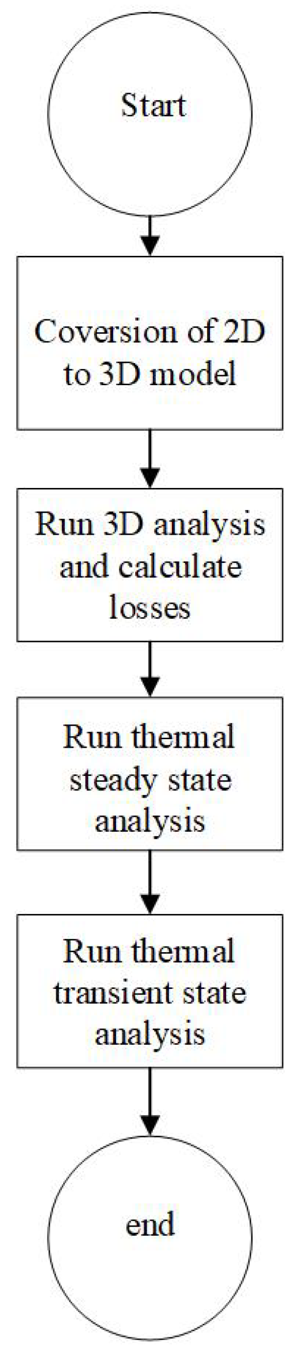
Section 5 discusses the thermal analysis of the machine and comparison between the FEA thermal analysis and LPMEC model; Section 6 presents the comparison of proposed and conventional machine; Section 7 provides the conclusion, which is an overview of the whole paper, and all the necessary points are discussed.

2. Design and Working Principle

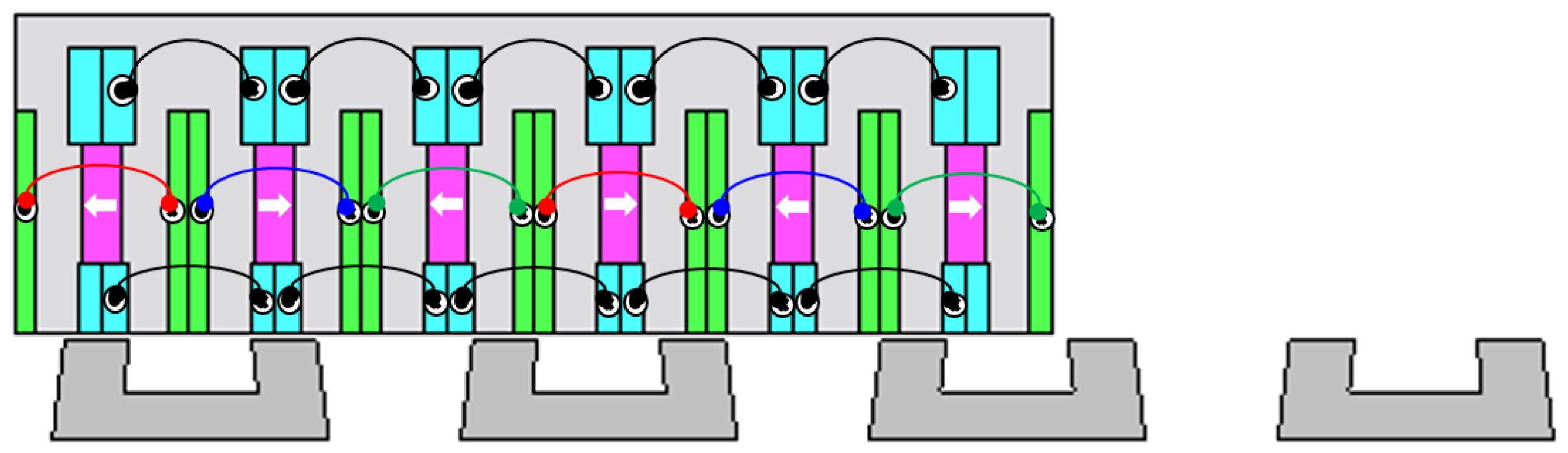
The design of the proposed model is shown in Figure 1. DC field windings (shown by cyan color) and armature windings (shown by green color) are placed on the short mover. Permanent magnets (PMs) (shown by magenta color) are placed inset in the mover poles magnetized in a parallel direction. The stator of the model is in the form of U-shaped modules, which are placed at a certain distance from each other, having no direct electrical or magnetic contact. Such an arrangement uses less iron than the conventional stator and not only decreases the cost of the machine but also improves the overall efficiency of the machine. A conventional stator is made up of a full-length iron core which becomes impractical for countries such as Pakistan and other developing countries.
To minimize the detent force of the machine, a suitable selection of mover slot M s and stator pole S p is made using Equation (1) [13].
S p = M s 1 ± n 2 q
where q denotes the number of phases and n represents any natural number. For various values of n, different stator pole numbers are studied and analyzed. It was noted that the machine has a sinusoidal flux linkage and unidirectional thrust force when M s / S p = 6 / 5 , 6 / 7 . The average thrust force for 6 / 5 is higher than 6 / 7 , so it is considered for further analysis. The velocity of the machine is dependent on the input source frequency and pole pitch of the machine and can be found by using Equation (2) [22].
v = f τ s
where v is the velocity, f is the frequency of the source, and τ s is the pole pitch of the machine. Flux linkage of the machine greatly varies (periodically) with the position of the mover relative to the stator position since the flux path changes as the mover changes its position. Considering phase A at two different points, both maximum and minimum flux linkage are analyzed, as shown in 
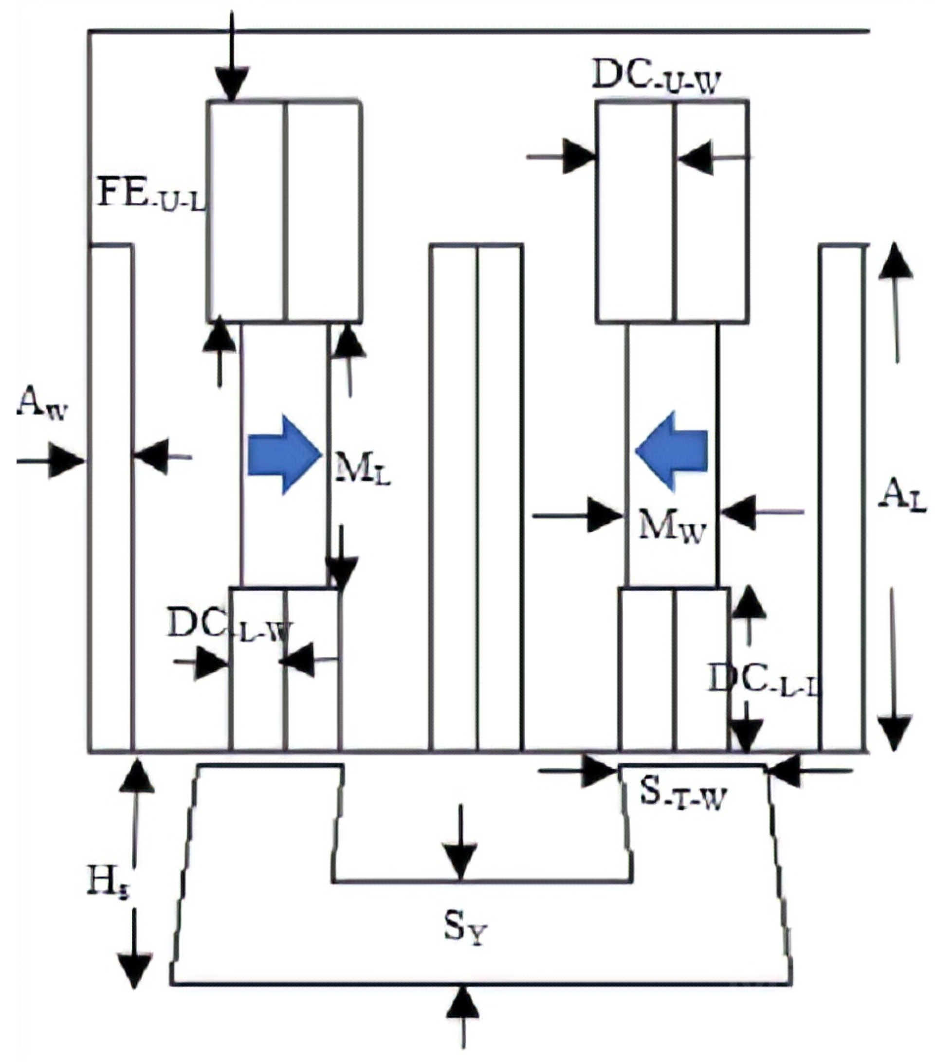
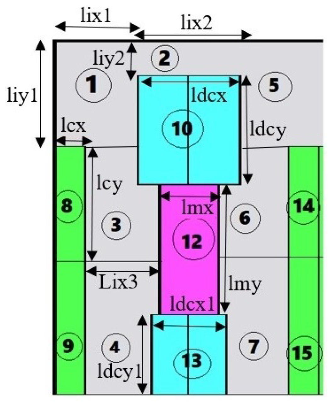
Figure 2a,b, respectively. At point 1, flux linkage due to phase A is at a positive maximum as the mover pole and stator tooth is completely aligned. Flux flows through the magnet, mover pole, air gap, and then into the stator tooth, completing the flux path back into the mover. A point 2, the flux linkage of phase A is at a negative maximum as the mover pole stator tooth is completely misaligned, while phase B and phase C have some value. The three phases are completely (120 degrees) apart. The direction of PM magnetization is set horizontal to that of the primary moving direction. The direction of PM and armature winding and DC is either clockwise or anticlockwise, to strengthen the overall machine’s flux linkage. Parameters of the machine are defined in Figure 3. The details of the parameters and their numerical values are tabularized in Table 1.
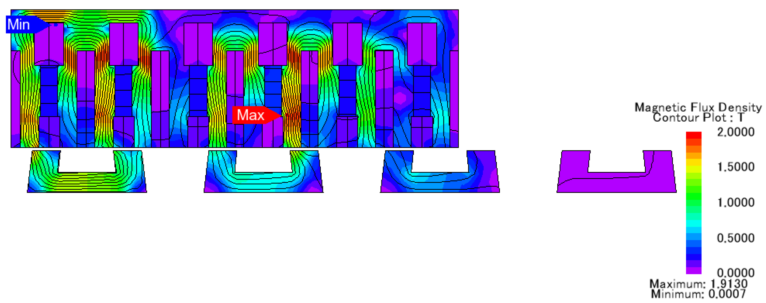
A flux density nephogram of the machine is shown in 
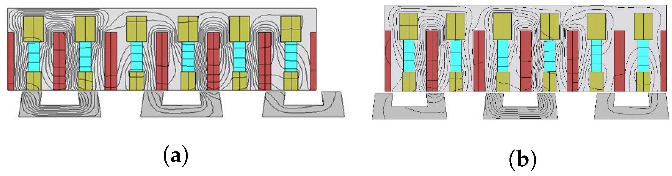
Figure 4, which reflects the magnetic flux density at various points of the machine, the path followed by the flux, and how flux switches from one mover pole to another pole through the modular stator. Slight saturation can be seen in the red regions in the nephogram, but it cannot be considered to cause a heating effect in the machine. The maximum flux density in the mover is 1.8 T, while in the case of the stator, maximum flux density is 1.42 T.
Coil configuration is dependent on the number of mover slots. Once the mover slot combination is confirmed, the coil configuration can be adjusted accordingly. Coil span is the axial distance through which a coil is wound. The coil span of the machine depends on the type of winding configuration used, either concentrated or simple.
C s = m a x [ f i x [ M s T s ] ] 1 f o r c o n c e n t r a t e d w i n d i n g 1
where M s represents number of mover slot, S p represents number of stator tooth, and f i x function is used to return integer value only. In case of a three-phase balanced system, the phases are separated 120 degrees apart. The phase separation for a machine can be found by C 0 .
C 0 = N m 3 N s ( 1 + 3 k )
k is any integer value, e.g., 0 , 1 , 2 , 3 , N s 2 . If a suitable value for k is not found, then that value of slot and pole combination shall not be chosen.

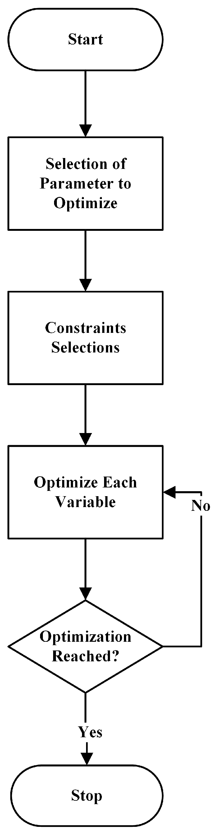
3. Optimization and Refinement of Machine Parameters

To increase the thrust force and efficiency of the machine, different machine parameters were optimized using single variable geometric optimization and JMAG inbuilt optimization (genetic algorithm (GA)). Thrust force amplification is considered the main target. In geometric optimization, a series of consecutive values are considered for geometry, and then the resulting thrust force is analyzed.

3.1. Geometric Optimization

Leading parameters such as split ratio (S.R) and armature slot width ( A w ) were optimized using geometric optimization. Figure 5 shows the flowchart of single variable geometric optimization.
Determination of optimal split ratio is a very important process of designing a machine as it decides not only the average thrust force but also the overall cost of the machine. If the selected value of the split ratio is low, it will reduce the stator height, which is suitable for railway transits. On the other hand, it will increase mover height and mass, resulting in the reduction of the average thrust force. The higher value of the split ratio resolves the mover mass problem but increases the stator volume, making the machine costly. The split ratio of the machine can be found by Equation (5) [23]. Table 2 shows the performance of the machine at different values of S . R .
S . R = H s + L g H s + H m + L g
A w = S l o t a r e a A L
The suitable height and width of the slot area are selected by keeping the overall slot area constant and changing the width and height of the machine. Increasing the width tends to decrease the height of the slot, and decreasing the width increases the height of the slot. The height and width of the machine are interrelated by Equation (6). Table 3 shows the thrust force profile at different slot width and height values.

3.2. Genetic Optimization

Stator tooth width, stator module spacing, crooked angle of the tooth, and starting angle of the machine are the four parameters that are optimized using genetic optimization. The width of the tooth helps with better flux linkage and better alignment of the mover pole and stator tooth. Teeth provide the necessary path for the flux linkage, and if teeth are too thin, the machine will suffer from saturation, and if the teeth are too thick, the flux will not switch into the next mover pole. GA was used to select a better-suited stator width, resulting in a higher thrust force and higher flux linkage.
The stator of the proposed machine is modular, and the modules are spaced at a certain distance, so better placement of the module becomes very important. It not only increases the coil flux linkage but is also used to minimize the usage of iron and the cost of the machine. GA single variable optimization is used to select the optimal spacing distance between the modules. Complete details of initial values, final values, and the constraint for GA are given in Table 4.
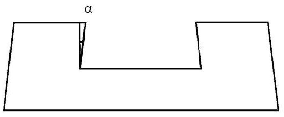
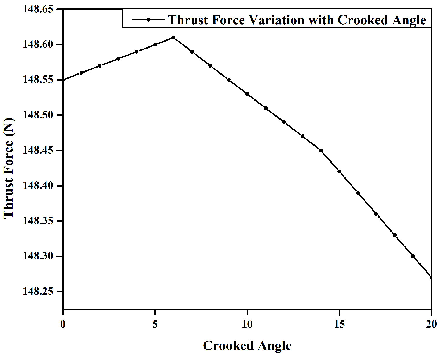
The crooked angle of the stator tooth is analyzed, and its effect on the machine’s performance is evaluated. It is the angle made by the inner side of the tooth with the yoke of the stator. Genetic optimization is employed, and it was witnessed that initially when the angle α is increased from 0 to 6.22 , the performance of the machine increases considerably; the best performance being noted at 6.22 . For an angle between 6.22 to 20 , a minute decrease is experienced in the thrust force. Figure 6 shows the crooked angle of the stator tooth, while Figure 7 shows the trend of how thrust force varies with the angle variation.
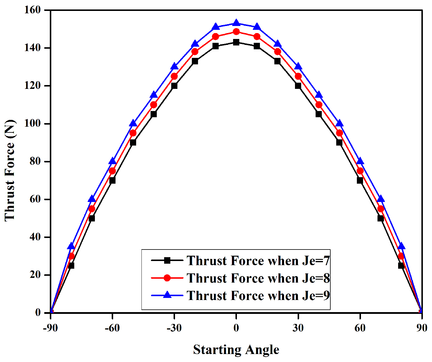
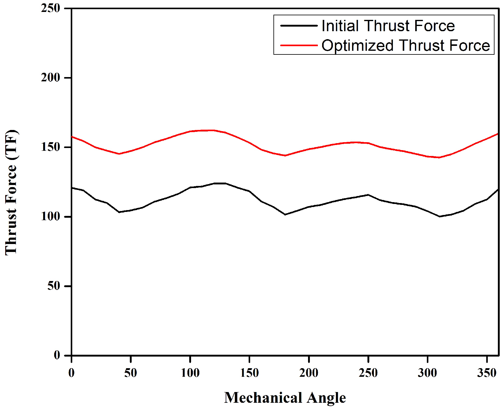
Figure 8 shows the average thrust force at different armature current starting angles. Three different J e are considered, and the resultant thrust force is analyzed. It can be seen that the machine performs best at a 0 
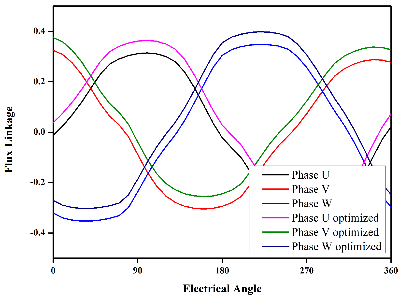
angle and the thrust force keeps on decreasing, going away from the origin in either direction. GA is used to optimize the starting angle, and its effect on the average thrust force is analyzed. The comparison of before and after optimization flux linkage and thrust force is shown in Figure 9 and Figure 10, respectively.
Table 5 shows before and after optimization values of parameters such as detent force, thrust force, and THD.

4. Analysis of Electromagnetic Performance

Parameters such as no-load flux linkage, detent force, total harmonic distortion (THD) of U phase, and thrust force are investigated for a boundary period of 1. No-load flux linkage φ ( p p ) , detent force ( F d ( p p ) ), and thrust force are directly calculated from the FEA. Mathematical calculations were performed to find T F d for on-load and THDs of no-load flux linkage. Fourier transform of no-load flux linkage is taken, after which Equation (7) is used to find THDs.
T H D = Σ k = 2 k φ k 2 φ 1
where φ 1 represents fundamental component, and φ 2 to φ k are the harmonics. Thrust force density with respect to mover volume of on-load study is calculated by Equation (8).
T F d = T F a v e r a g e V m
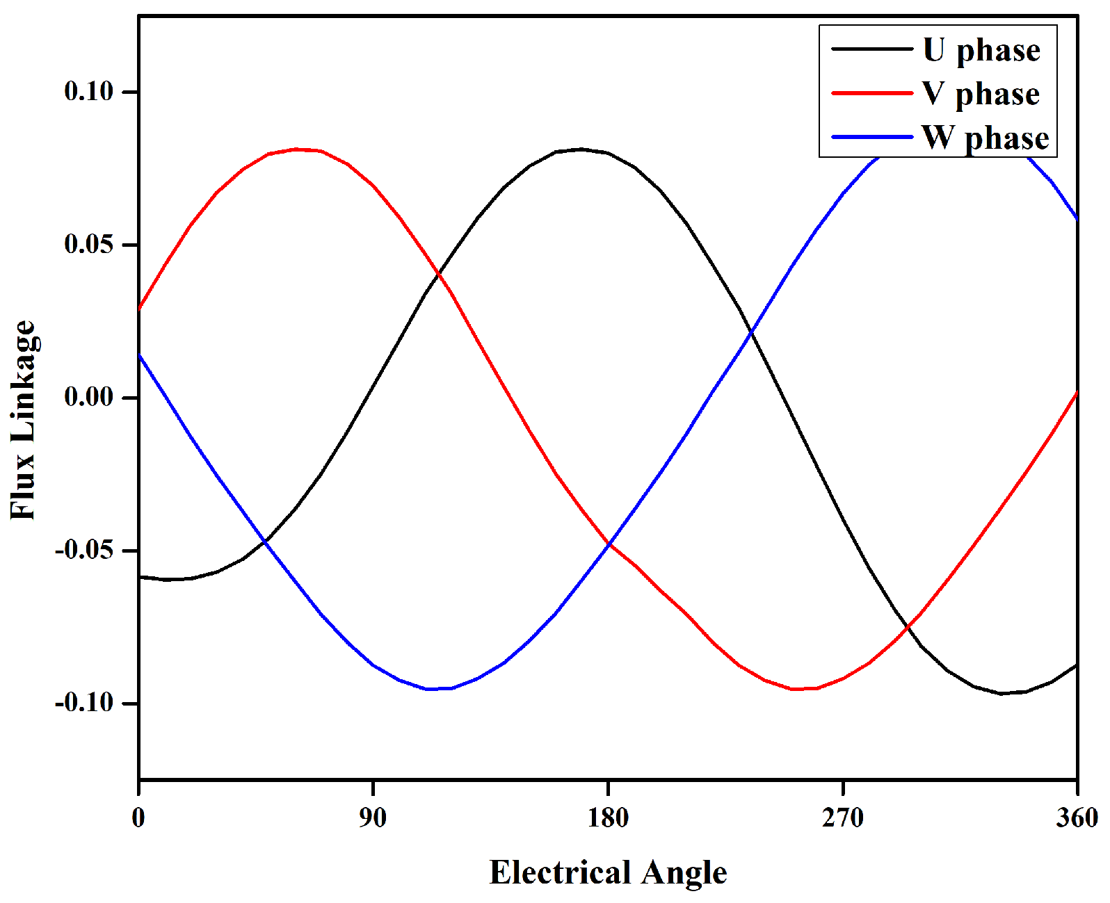
Figure 11 represent the three-phase no-load flux linkage, all the phases are purely sinusoidal. A difference can be noted between the positive maximum value and the negative value, which points towards the presence of a leakage flux. The flux regulation capability at various DC excitation current is shown in 
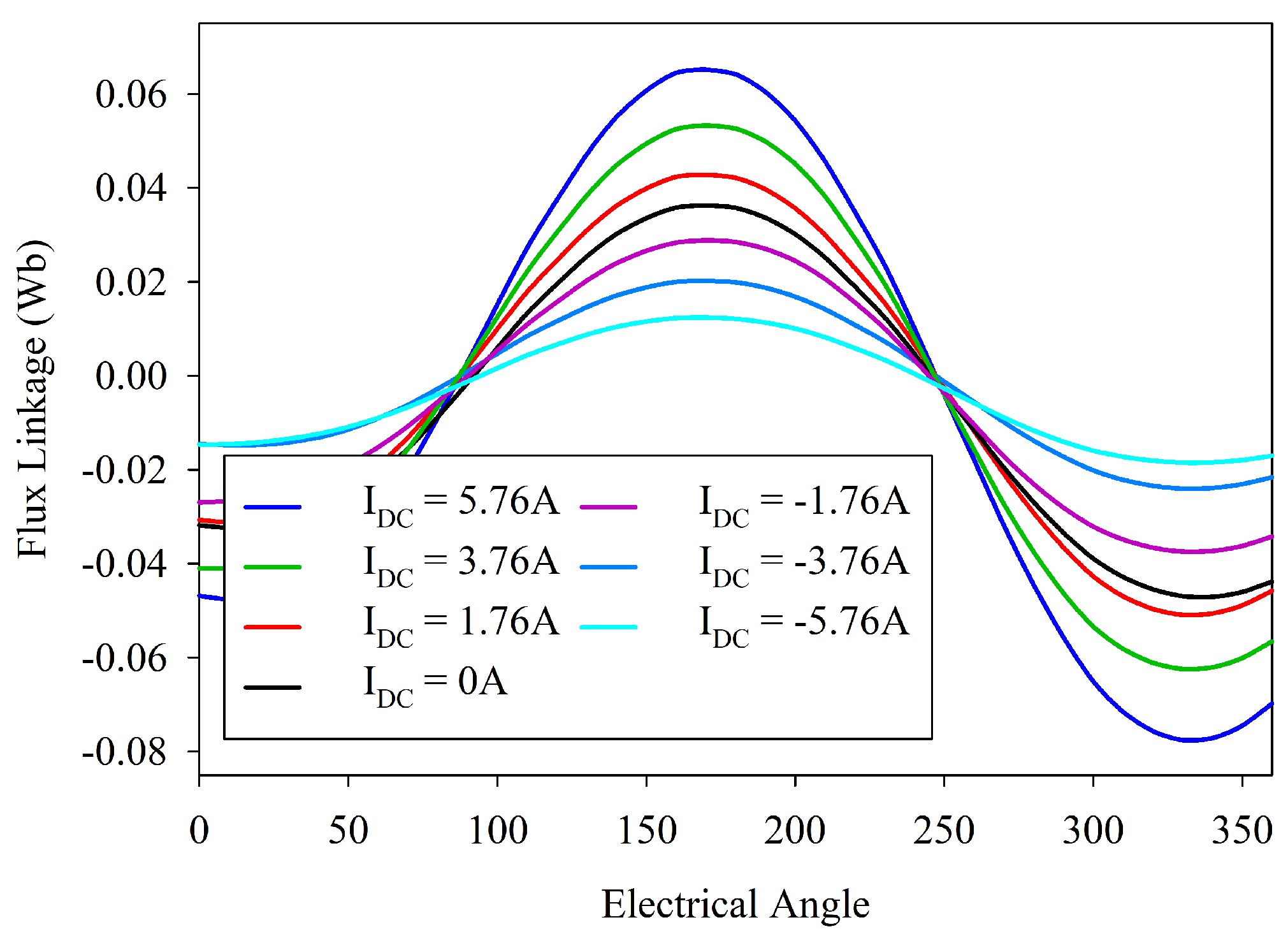
Figure 12. The figure shows that the flux of the proposed machine can be easily controlled by varying the DC current.
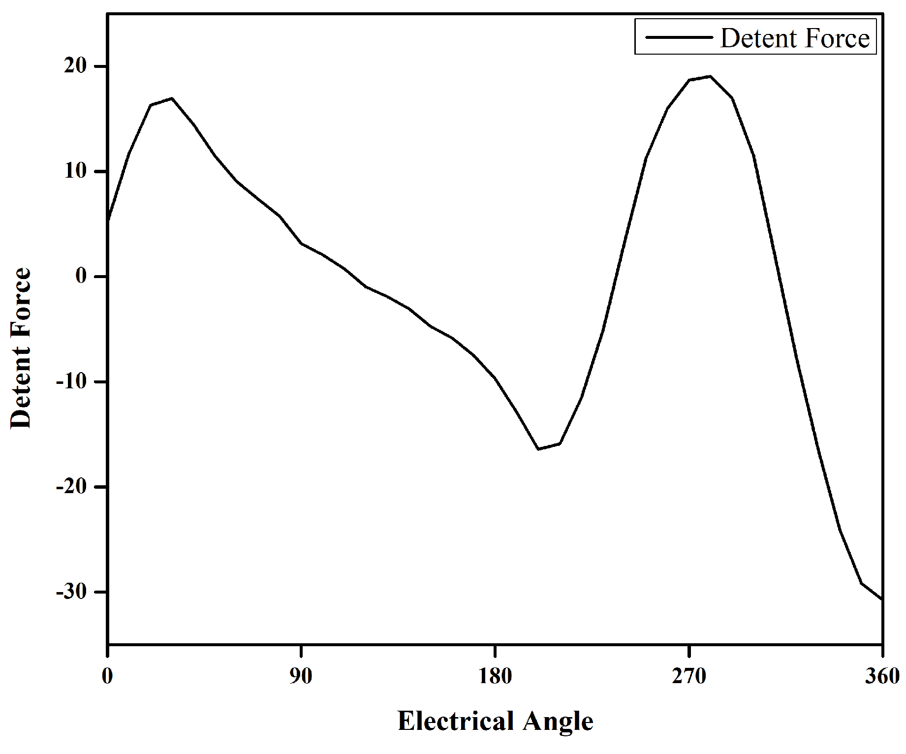
Detent force is analyzed in the no-load study when the AC circuit is open, and only DC is fed to the machine. The presence of a magnet makes it the combination of both DC and PM. Depending on its value, it either pulls the machine backward or pushes it forward. Positive detent force helps push the machine forward, while negative detent force pulls the machine backward. This push and pull are the main reasons for thrust force ripple [24,25]. A bipolar detent force can be seen in Figure 13.
The thrust force of the machine is unipolar in nature, as shown in Figure 10. The effect of detent force pull and push can be observed from the thrust force graph. When the value of detent force decreases, i.e., at angle 30 to 120 , 160 to 240 , and 300 to 360 , the thrust force decreases, but when the detent force increases, the thrust force also increases. Table 6 shows the detailed values for THD, peak-to-peak no-load flux linkage, thrust force, and thrust force density.
Performance of the machine is evaluated at different J a ; it can be observed that the thrust force increases linearly up to some extent, but then the linearity is disturbed because the machine is moving toward saturation.
Figure 14 shows thrust force at different J a and J e values. Two different values for J e 
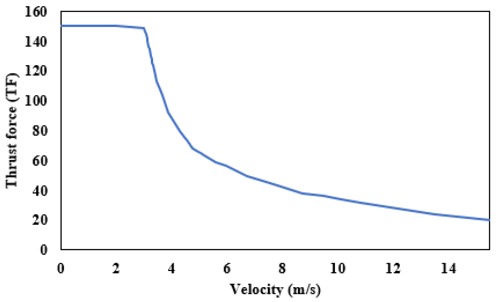
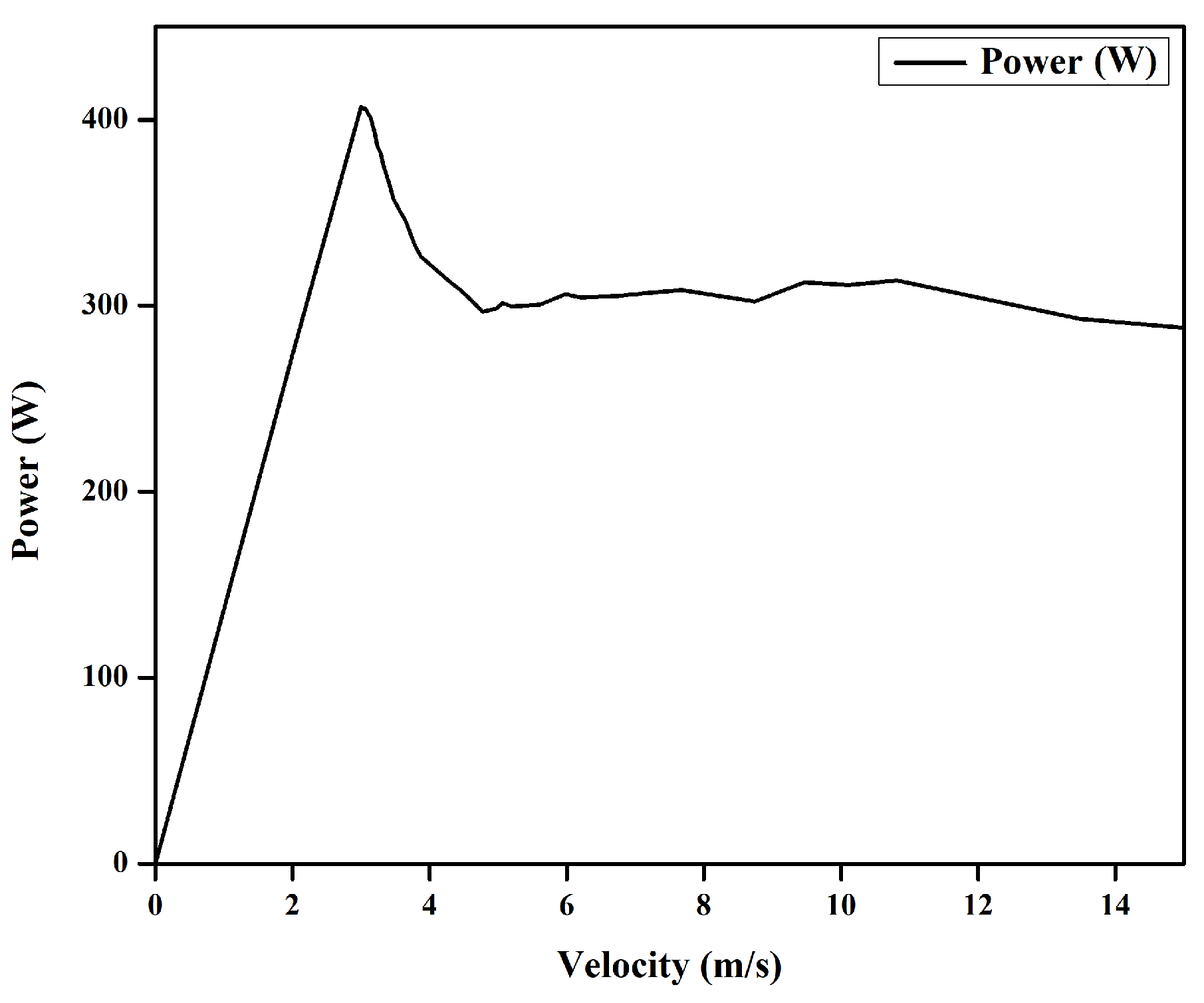
are considered, and the respective thrust force is shown. Thrust force profiles and power of the machine are evaluated at different velocities and are presented in Figure 15 and Figure 16.
Different points are considered in the thrust force and velocity graph, and both iron core losses and copper losses are calculated. Overall efficiency of the machine is calculated considering both iron and copper loss. Copper loss of the machine can be calculated using Equation (9).
P c = I ρ J L N Q ( 1000 )
where I represents armature current, ρ represents resistivity of the conductor, L is the length of the wire, J a is the current density of the wire, N is the number of conductors, and Q denotes number of slot pairs.
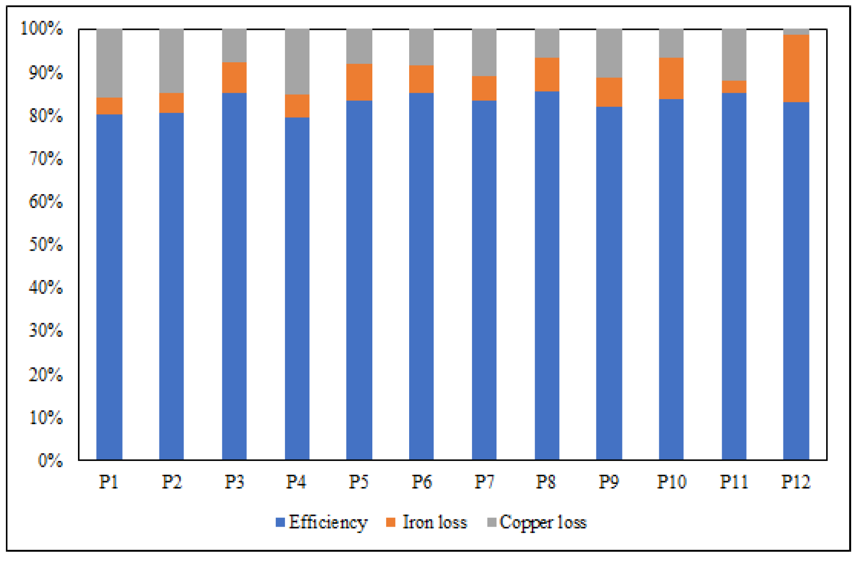
Iron losses of the machine are calculated directly from JMAG simulation, and the overall efficiency of the machine is calculated. Figure 17 shows losses and overall efficiency of the machine at different velocities. Use of a modular stator reduces the iron volume, thus lowers the iron core losses, increasing the efficiency of the machine. A total of 13 % improvement in efficiency is noted using a modular stator because of the iron losses minimization.

5. Thermal Analysis

Thermal analysis of the machine has three broad steps: the first one is calculation of three dimensional magnetic losses, thermal analysis, and comparing analytically with lumped parametric model equivalent circuit (LPMEC). The whole process of thermal analysis is shown in the form of a flowchart in Figure 18. The whole procedure of analysis and model building is defined by [20].

5.1. Magnetic Analysis

Since accuracy of the machine is higher in the 3D model, 3D magnetic analysis is considered. Losses calculated are calculated after necessary condition and material setting, and then the losses are used in the thermal analysis.

5.2. Thermal Analysis

Since thermal properties of the machine greatly depend on the nature of the material, conductivity of each material is calculated along with the specific heat capacity of the materials. Various properties of materials are tabulated in Table 7. Room temperature is considered as a reference for the whole process. Three different types of boundaries were defined for various contact types. For direct contact between the two parts, a contact thermal resistance boundary is defined, and heat transfer boundaries are defined for points where heat transfer in the form of convection takes place. Radiation type of heat transfer is ignored in this study. Figure 19 represents the distribution of temperature throughout the machine design. Most of the heat accumulation takes place in the mover as it contains all the active parts (coils and magnets). The stator remains at room temperature as there is no direct contact between the mover and the stator.

5.3. LPMEC Model

Software simulation of the thermal analysis is validated by an LPMEC model, taking advantage of the heat and electrical system analogy, in which each part of the machine is represented in the form of a resistor, and the value of the resistor depends on its areas and specific heat capacity. A few assumptions were considered while developing this model, and they are given below.
  • Only two-dimensional heat flow is considered.
  • All the material used in the machine are considered isotropic; heat travels equally in all directions.
  • Radiation of the heat is ignored.
The machine is divided into three major parts and each part is then represented by a specific value resistance. Figure 20 represents the various parts of the machine. The coils and magnets are divided into two exactly equal parts while the iron core is represented as single part. Thermal conductivity of each part is presented in Table 8, while resistance of each part can be calculated using Equations (10)–(14).
R i 1 x = l i x 1 λ f e l i y 1 L a , R i 1 y = 0.5 l i y 1 λ f e l i x 1 L a
R i 2 x = l i x 2 λ f e l i y 2 L a , R i 2 y = 0.5 l i y 2 λ f e l i x 2 L a
R i 3 x = l i x 3 λ f e l i y 3 L a , R i 3 y = 0.5 l i y 3 λ f e l i x 3 L a
R i 4 x = l i x 4 λ f e l i y 4 L a , R i 4 y = 0.5 l i y 4 λ f e l i x 4 L a
R m = l m y 3 λ P M l m x L a
Equivalent thermal resistance is considered in the case of the slot as the temperature distribution is not uniform because of the insulation and copper winding air gaps. Equation (15) is used to find equivalent thermal resistance.
R c x = l c x λ c u l c y L a , R c y = 0.5 l c y λ c u l c x L a
Thermal capacity of the machine is represented in the form of capacitance in the LPMEC model, with its values calculated from Equations (16) and (17).
C = m × c p
m = ρ × V
The developed LPMEC model presented in Figure 21 is then simulated through MATLAB Simulink software, and temperature rise of each part and the temperature rise of the whole machine are observed, shown in Figure 22.

5.4. Comparison of FEA and LPMEC

Analysis of both FEA and LPMEC is compared, and a very good agreement between the two is observed. Figure 22 shows thermal analysis of each part, according to the division mentioned earlier, observed and compared with the average temperature rise of FEA analysis. Figure 23 represents the comparison between the average temperature rise from both methods. Overall, a relative difference of less than 4 % is observed, which is quite negligible, since the FEA analysis is performed in three dimensions and is therefore more accurate, while in the case of LPMEC, we have only a two-dimensional flow of temperature.

6. Comparison with Conventional LHFSPM

Finally, the proposed LHFSPM is compared to the conventional design [26] in Table 9, which includes a complete comparison. Both the machines use the same dimensions and same type of PM, while the proposed machine achieves the same performance by reducing the volume of PM by 25.56%.

7. Conclusions

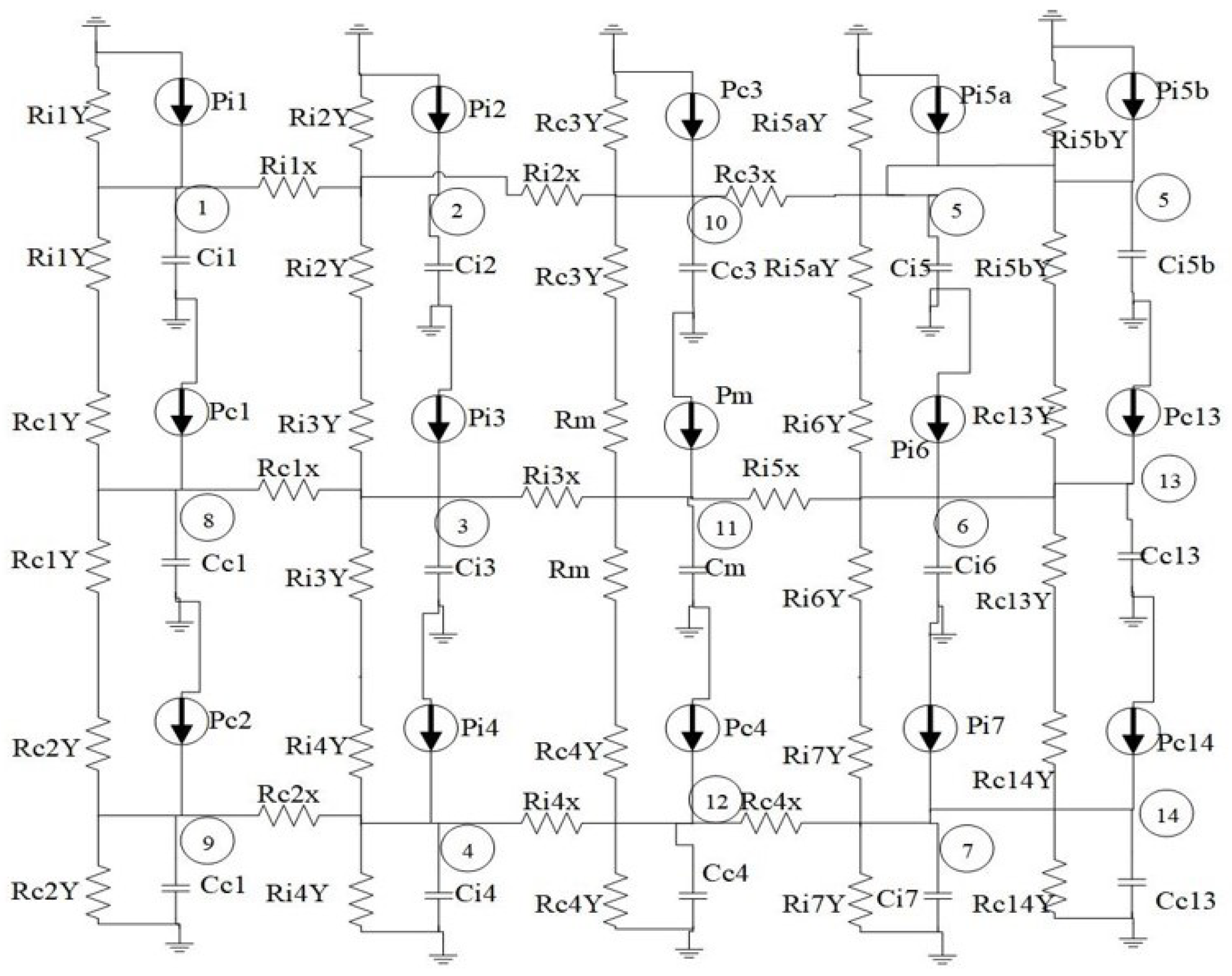
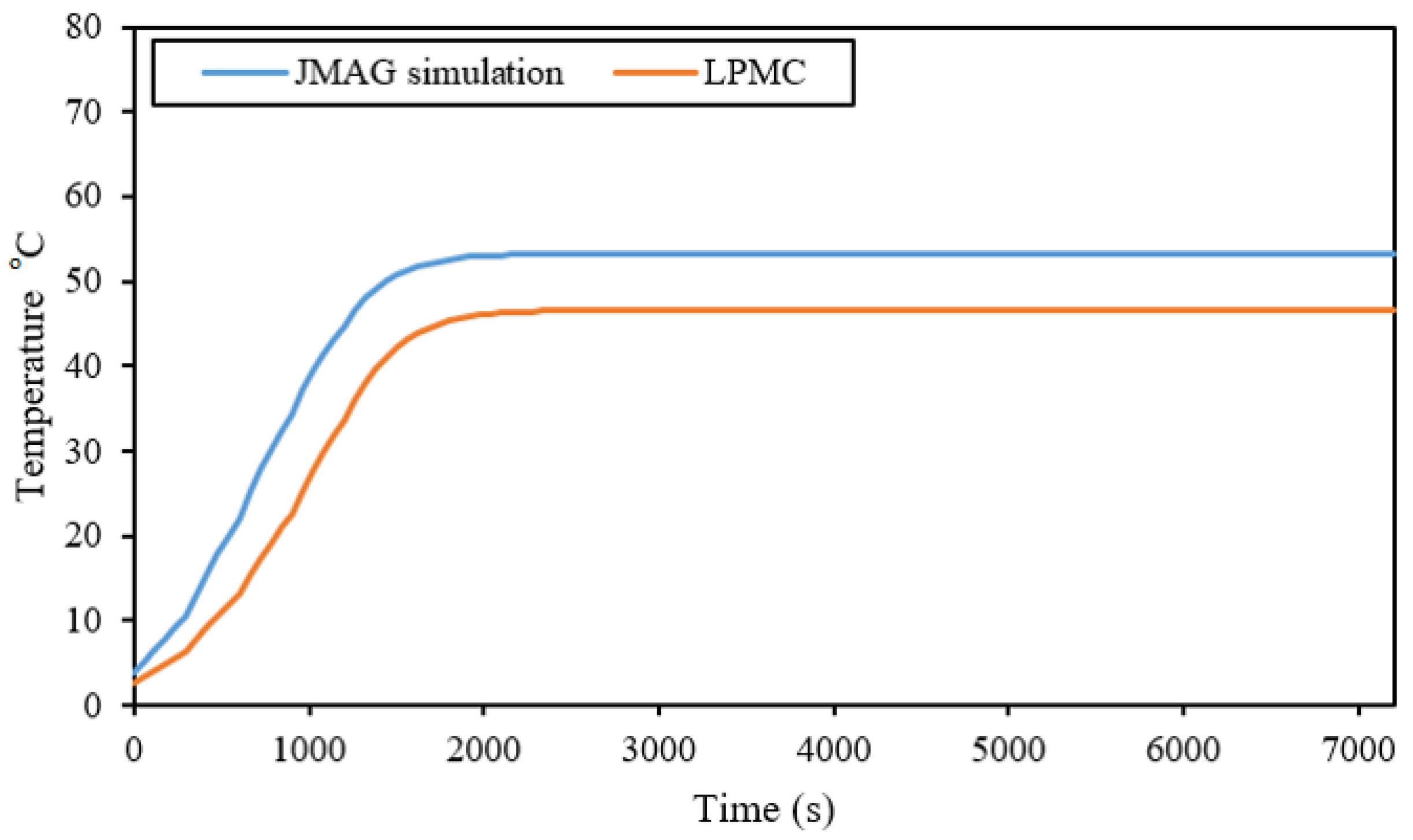
In this paper, a LHFSM with a crooked tooth modular stator is proposed. Electromagnetic performance parameters such as no-load flux linkage, detent force, TF, and thrust force profile at different velocities were studied and analyzed. The crooked tooth technique was devised to improve the thrust force of the machine, and its effect at different angles was presented. Geometric optimization technique was used to enhance the thrust force and mitigate detent force and THD of the proposed machine. GA technique was used to optimize the stator tooth, starting angle, and crooked angle. TF of the machine was improved from an initial value of 129.53 N to an optimized value of 150.1823 N, T F d was increased from 243.3 kN/m3 to 306.61 kN/m3, φ ( p p ) was increased from 0.12 T to 0.14 T, F d ( p p ) was increased from 0.2601 N to 8.4 N, and the value for THD was slightly reduced from the initial value. Iron losses for the machine were minimized significantly by the use of the modular stator and optimal placement of the modules. In the end, thermal analysis of the machine was performed and was then validated by the LPMEC model. A relative percentage error of 3 % was observed.

Author Contributions

Conceptualization, H.U.J. and F.K.; methodology, H.U.J.; software, H.U.J., B.U. and M.Q.; validation, H.U.J., B.U. and M.Q.; resources, F.K., A.H.M. and A.A.A.; original draft preparation, H.U.J.; review and editing, B.U. and F.K.; supervision, F.K.; project administration, F.K. and A.H.M.; funding acquisition, A.H.M. and A.A.A. All authors have read and agreed to the published version of the manuscript.

Funding

There is no external funding.

Data Availability Statement

Not applicable.

Acknowledgments

This work was supported by COMSATS University Islamabad, Abbottabad Campus.

Conflicts of Interest

The authors declare no conflict of interest.

Abbreviations

A C w AC winding slot area
D C w DC winding slot area
DSLFSMDouble-sided LFSM
G . A . Genetic algorithm
HEDSLFSMHybrid excited double-sided linear flux switching machine
HELFSMsHybrid excited LFSMs
HEVsHybrid electric vehicles
LFSMsLinear flux switching machines
LIMsLinear induction machines
LPMCLumped parametric magnetic equivalent circuit
PMLFSMsPermanent magnet LFSMs
S . R Split ratio
SLFSMSingle-sided LFSM
S T W Stator tooth width
TFThrust force

References

  1. Hu, D.; Xu, W.; Dian, R.; Liu, Y.; Zhu, J. Loss minimization control of linear induction motor drive for linear metros. IEEE Trans. Ind. Electron. 2017, 65, 6870–6880. [Google Scholar] [CrossRef]
  2. Lv, G.; Zeng, D.; Zhou, T.; Liu, Z. Investigation of forces and secondary losses in linear induction motor with the solid and laminated back iron secondary for metro. IEEE Trans. Ind. Electron. 2016, 64, 4382–4390. [Google Scholar] [CrossRef]
  3. Zou, J.; Xu, W.; Yu, X.; Liu, Y.; Ye, C. Multistep model predictive control with current and voltage constraints for linear induction machine based urban transportation. IEEE Trans. Veh. Technol. 2017, 66, 10817–10829. [Google Scholar] [CrossRef]
  4. Lv, G.; Zhou, T.; Zeng, D. Influence of the ladder-slit secondary on reducing the edge effect and transverse forces in the linear induction motor. IEEE Trans. Ind. Electron. 2018, 65, 7516–7525. [Google Scholar] [CrossRef]
  5. Sokolov, M.; Saarakkala, S.E.; Hosseinzadeh, R.; Hinkkanen, M. A dynamic model for bearingless flux-switching permanent-magnet linear machines. IEEE Trans. Energy Convers. 2020, 35, 1218–1227. [Google Scholar] [CrossRef] [Green Version]
  6. Cao, R.; Cheng, M.; Mi, C.C.; Hua, W. Influence of leading design parameters on the force performance of a complementary and modular linear flux-switching permanent-magnet motor. IEEE Trans. Ind. Electron. 2013, 61, 2165–2175. [Google Scholar] [CrossRef]
  7. Huang, W.; Hua, W.; Yin, F.; Yu, F.; Qi, J. Model predictive thrust force control of a linear flux-switching permanent magnet machine with voltage vectors selection and synthesis. IEEE Trans. Ind. Electron. 2018, 66, 4956–4967. [Google Scholar] [CrossRef]
  8. Huang, X.Z.; Yu, H.C.; Zhou, B.; Li, L.Y.; Gerada, D.; Gerada, C.; Qian, Z.Y. Detent-force minimization of double-sided permanent magnet linear synchronous motor by shifting one of the primary components. IEEE Trans. Ind. Electron. 2019, 67, 180–191. [Google Scholar] [CrossRef]
  9. Hao, W.; Wang, Y. Thrust force ripple reduction of two c-core linear flux-switching permanent magnet machines of high thrust force capability. Energies 2017, 10, 1608. [Google Scholar] [CrossRef] [Green Version]
  10. Song, J.; Dong, F.; Zhao, J.; Lu, S.; Dou, S.; Wang, H. Optimal design of permanent magnet linear synchronous motors based on taguchi method. IET Electr. Power Appl. 2017, 11, 41–48. [Google Scholar] [CrossRef]
  11. Ma, W.; Wang, X.; Wang, Y.; Li, X. A hts-excitation modular fluxswitching linear machine with static seals. IEEE Access 2019, 7, 32009–32018. [Google Scholar] [CrossRef]
  12. Wang, Z.-Q.; Long, Z.-Q.; Li, X.-L. Fault analysis and tolerant control for high speed pems maglev train end joint structure with disturbance rejection. J. Electr. Eng. Technol. 2019, 14, 1357–1366. [Google Scholar] [CrossRef]
  13. Mohamed Jaffar, M.Z. Modeling and Analysis of Saturated Inductances and Torque Ripple Components in Interior Permanent Magnet Motors. Ph.D. Thesis, North Carolina State University, Raleigh, NC, USA, 2019. [Google Scholar]
  14. Ullah, B.; Khan, F.; Milyani, A.H. Analysis of a Discrete Stator Hybrid Excited Flux Switching Linear Machine. IEEE Access 2022, 10, 8140–8150. [Google Scholar] [CrossRef]
  15. Gas, P.; Kurgan, E. Evaluation of thermal damage of hepatic tissue during thermotherapy based on the arrhenius model. In Proceedings of the 2018 Progress in Applied Electrical Engineering (PAEE), Koscielisko, Poland, 18–22 June 2018; pp. 1–4. [Google Scholar]
  16. Zhao, J.; Guan, X.; Li, C.; Mou, Q.; Chen, Z. Comprehensive evaluation of inter-turn short circuit faults in pmsm used for electric vehicles. IEEE Trans. Intell. Transp. Syst. 2020, 22, 611–621. [Google Scholar] [CrossRef]
  17. Li, G.; Ojeda, J.; Hoang, E.; Gabsi, M.; Lecrivain, M. Thermal–electromagnetic analysis for driving cycles of embedded flux-switching permanent-magnet motors. IEEE Trans. Veh. Technol. 2011, 61, 140–151. [Google Scholar] [CrossRef] [Green Version]
  18. Thomas, A.; Zhu, Z.; Li, G. Thermal modelling of switched flux permanent magnet machines. In Proceedings of the 2014 International Conference on Electrical Machines (ICEM), Berlin, Germany, 2–5 September 2014; pp. 2212–2217. [Google Scholar]
  19. Cai, X.; Cheng, M.; Zhu, S.; Zhang, J. Thermal modeling of fluxswitching permanent-magnet machines considering anisotropic conductivity and thermal contact resistance. IEEE Trans. Ind. Electron. 2016, 63, 3355–3365. [Google Scholar] [CrossRef]
  20. Jan, H.U.; Khan, F.; Ullah, B.; Qasim, M.; Khan, M.A.; Hafeez, G.; Albogamy, F.R. Design and Thermal Modeling of Modular Hybrid Excited Double-Sided Linear Flux Switching Machine. Energies 2021, 14, 8511. [Google Scholar] [CrossRef]
  21. Jan, H.U.; Khan, F.; Qasim, M.; Ullah, B.; Yousaf, M.; ul Islam, Z. Thermal and Stress Analysis of Linear Hybrid Excited Flux Switching Machine with Modular Stator. In Proceedings of the 2021 International Conference on Emerging Power Technologies (ICEPT), Topi, Pakistan, 10–11 April 2021; pp. 1–6. [Google Scholar] [CrossRef]
  22. Ur Rahman, L.; Khan, F.; Khan, M.A.; Ahmad, N.; Khan, H.A.; Shahzad, M.; Ali, S.; Ali, H. Modular rotor single phase field excited flux switching machine with non-overlapped windings. Energies 2019, 12, 1576. [Google Scholar] [CrossRef] [Green Version]
  23. Liang, J.; Ming, Z.; Ji, X. Feeding apparatus directly driven by optimal topology flux switching permanent magnet linear motor. Electr. Power Components Syst. 2019, 47, 903–913. [Google Scholar] [CrossRef]
  24. Zeng, Z.; Shen, Y.; Lu, Q.; Wu, B.; Gerada, D.; Gerada, C. Investigation of a partitioned-primary hybrid-excited flux-switching linear machine with dual-pm. IEEE Trans. Ind. Appl. 2019, 55, 3649–3659. [Google Scholar] [CrossRef]
  25. Zhao, J.; Mou, Q.; Guo, K.; Liu, X.; Li, J.; Guo, Y. Reduction of the detent force in a flux-switching permanent magnet linear motor. IEEE Trans. Energy Convers. 2019, 34, 1695–1705. [Google Scholar] [CrossRef]
  26. Hwang, C.C.; Li, P.L.; Liu, C.T. Design and analysis of a novel hybrid excited linear flux switching permanent magnet motor. IEEE Trans. Magn. 2012, 48, 2969–2972. [Google Scholar] [CrossRef]
Figure 1. 2D view of the proposed model.
Energies 15 05275 g001
Figure 2. Flux linkage at two different positions. (a) Point 1; (b) Point 2.
Energies 15 05275 g002
Figure 3. Parameters of the proposed model.
Energies 15 05275 g003
Figure 4. Nephogram of machine flux density.
Energies 15 05275 g004
Figure 5. Flowchart of geometric optimization.
Energies 15 05275 g005
Figure 6. Crooked angle.
Energies 15 05275 g006
Figure 7. Variation of thrust force with crooked angle.
Energies 15 05275 g007
Figure 8. Thrust force at different starting angle.
Energies 15 05275 g008
Figure 9. Flux linkage before and after optimization.
Energies 15 05275 g009
Figure 10. Thrust force comparison before and after optimization.
Energies 15 05275 g010
Figure 11. No-load flux linkage.
Energies 15 05275 g011
Figure 12. Flux regulation capability of the proposed machine.
Energies 15 05275 g012
Figure 13. Detent force.
Energies 15 05275 g013
Figure 14. Thrust force at different J a .
Energies 15 05275 g014
Figure 15. Thrust force at different velocities.
Energies 15 05275 g015
Figure 16. Output power at different velocities.
Energies 15 05275 g016
Figure 17. Efficiency at different points.
Energies 15 05275 g017
Figure 18. Flowchart of thermal analysis.
Energies 15 05275 g018
Figure 19. Temperature distribution.
Energies 15 05275 g019
Figure 20. Division of the machine.
Energies 15 05275 g020
Figure 21. LPMEC model.
Energies 15 05275 g021
Figure 22. Thermal analysis of each part.
Energies 15 05275 g022
Figure 23. Average temperature rise comparison.
Energies 15 05275 g023
Table 1. Detailed parameters of the proposed model.
ParametersValues
Pole Pitch, τ s 26.1984 mm
Velocity, V4 m/s
Stator Height, H s 12.56 mm
Stack Length90 mm
Mover Height, H m 12.56 mm
Stator Tooth Width, S T W 8.33338 mm
Air gap, L g 0.8 mm
Armature winding turns136
Maximum current DC5.76 A
Permanent magnetFerrite_Br = 0.4 T
Maximum thrust force150.1823 N
Split ratio, S . R 0.246
Armature slot width, A w 2.4 mm
Armature slot length, A L 31.241 mm
Upper DC slot width, D C U W 12.55 mm
Upper DC slot length, D C U L 4.3 mm
Lower DC slot width, D C L W 3.119 mm
Lower DC slot length, D C L L 9.264 mm
Table 2. Performance indicator.
S.R0.150.2250.2350.2460.257
T F a v e r a g e (N)119.17121.72128.43133.48129.13
φ ( p p ) (Wb)0.0100.01070.0170.0120.018
F d ( p p ) (N)0.02370.2150.2810.3010.260
T F d (kN/m3)243.30248.51262.21272.52263.64
THD (%)12.9311.2313.7514.113.42
Table 3. Performance after geometric optimization.
IndicatorStage1Stage2Stage3Stage4Stage5Stage6
A L (mm)35.7134.0932.6031.2528.8427.77
A w (mm)2.12.22.32.42.52.6
S l o t a r e a (mm2)757575757575
T F a v e r a g e (N)131.21132.8133.48134.17135.01135.98
Table 4. Performance of the machine after Genetic Optimization.
ParametersInitial ValueFinal ValueConstraintsTF
S T W 12.24 mm8.338 mm7 mm < S T W < 13 mm136.08 N
S S 11 mm13.01 mm10 mm < S S < 15 mm140.601 N
Table 5. Overall performance of the machine.
ItemsInitial ValueAfter OptimizationThrust Force BeforeThrust Force AfterTHD F ( detent p p )
S.R0.2250.246129.5353 N133.4818 N14.1%0.2601 N
A w 2.3 mm2.6 mm133.4818 N135.9811 N13.7%0.498 N
S T W 12.24 mm8.33 mm135.9811 N136.08 N11.79%2.1 N
S S 11 mm13.01 mm136.08 N140.60 N13.21%4.12 N
α 06.22140.60 N148.608 N12.01%7.2 N
θ 100148.608 N150.1823 N12.54%8.4 N
Table 6. Performance indicators.
ParametersValues
φ ( p p ) 0.12 T
φ ( + m a x ) 0.05 T
φ ( m a x ) 0.07 T
THD (%)12.10
T F a v e r a g e 129.53 N
F ( d e t e n t p p ) 8.4 N
T F d 263.64 kN/m3
Table 7. Material Properties for thermal analysis.
Part of the MachineDensity (Kg/m3)Specific Heat (J/Kg°C)Thermal Conductivity (W/(m°C))
Modular Stator765046023
Mover765046023
Winding coils4000380380
Table 8. Thermal conductivity of various parts.
VariableThermal Conductivity
λ f e 9 W/m°C
λ c u 28 W/m°C
λ P M 0.68 W/m°C
λ c u 28 W/m°C
Density of iron ρ i 7870 Kg/m3
Density of copper ρ c 8940 Kg/m3
Density of ferrite magnet ρ P M 5000 Kg/m3
Table 9. Comparison of proposed and conventional LHFSPM.
ParameterProposed[26]
Mover length131 mm
Stack length90 mm
Airgap0.8 mm
Rated velocity4 m/s
DC current5.76 A6 A
AC turns230276
DC turns8181
PM typeFerrite
PM volume41.24 cm355.4 cm3
Thrust force150.18 N149.45 N
Publisher’s Note: MDPI stays neutral with regard to jurisdictional claims in published maps and institutional affiliations.

