1. Introduction
The widespread use of ICE (internal combustion engine) automobiles has led to an increase in pollution and energy constraints in recent years. The use of electric vehicles (EVs) has the potential to reduce environmental stress, reduce pollution, and limit the number of vehicles requiring charging [
1]. Electric vehicles (EVs) rely heavily on electric motors [
2]; thus, numerous electric motors were evaluated and analyzed to determine which would be the most effective for various applications. These days, brushless DC motors (BLDCMs), induction motors, and different permanent magnet (PM) machines are some of the motor types other than SRM motors that can be used effectively in variable-speed applications [
3,
4]. In comparison with conventional motors, SRMs are appealing to researchers due to their low complexity, high durability, cost-effectiveness, and ease of production [
5,
6]. SRM appears to have the same power density as induction motors, and its reliability appears to be far superior to that of DC series and permanent magnet motors [
7]. As the SRM lacks the mechanical components of other conventional motors, such as permanent magnets and rotor windings, it can be utilized in high-temperature environments [
8]. Low torque and power density, compared with permanent magnet motors, as well as significant torque ripple, are two drawbacks that limit its utility [
9].
Numerous researchers are devoted to reducing the machine architecture to the level required by applications in order to address these problems and boost the performance of SRMs. Prior research has demonstrated that numerous approaches to switched reluctance motors focus on innovative controller circuits [
10,
11,
12], core segmentation [
13,
14,
15,
16], and hybrid excitations (HESRMs).
Using sophisticated controller circuits, the switching circuit of the stator of an SRM can be optimized to provide maximum torque. Precision phase-winding switching makes it possible to tailor the performance of modern electronic converters to specific applications [
17]. This accurate switching method permits substantial control over the torque ripple of the motor. In order to increase the available flux in the air gap and the resulting flux, the segmentation method [
18] is applied to either the stator or rotor cores. By limiting the flux to the separated regions, the average torque of the active region is increased. This segmented system diminishes mechanical strength and contributes to higher costs [
19] due to the increased production complexity. Due to the internal flux’s reciprocal coupling, the overall efficiency of the segmented core is diminished. Drive circuits with multiple stator segments may be used for low- and high-speed applications and provide more power and torque per ampere [
20]. This technique increases torque output at the expense of machine durability [
21]. The third option (HESRM) is permanent magnet hybrid-excited switched reluctance motors.
SRMs underwent a paradigm shift with the introduction of the hybrid excitation technique, which substantially increased their ability to generate electromagnetic torque. However, this approach uses PMs into the structure of the machine to increase the motor’s average torque. A 12/8 HESRM with a modular stator was presented in a stator segmented with PMs [
22]. There is evidence that it can transport a maximum flux density at a higher torque [
23]. The flux capacity is increased by 34.7% compared with the segmented SRM without PM [
24]. As a result, the average torque is 71.4% greater than the conventional SRM. A comparison study of a segmented stator permanent magnet hybrid excitation SRM drive [
25] reported that the static average torque of the segmented HESRM is 1.16 to 1.39 times that of the standard one. There were six permanent magnets (PMs) in the stator of the machine; due to the behavior of the PMs, this could cause cogging torque. It has been demonstrated that SRM with auxiliary winding and permanent magnets is 3% more efficient and reduces size and weight by the same amount [
26]. The HESRM, meanwhile, combines the benefits of the permanent magnet machine and the electromagnet machine to create a hybrid excitation of the double salient machine [
27]. The rare-earth permanent magnets in the rotor core of the 6-slot 8-pole hybrid excitation flux switching machine (HEFSM) are an innovative design element that contributes to the machine’s high power density by providing adequate mechanical strength with enhanced electromagnetic performances [
28]. The suggested machine, the HEFSM, has an efficiency ranging from 92 to 97 percent, and it is also used to dampen vibration and acoustic noise. Similar to low-power, low-cost applications, single-phase hybrid SRMs are utilized for low-power, low-cost applications. The new low-cost hybrid SRM for variable-speed pumps contains permanent magnets in the shape of rectangular shards. As a result, both the average torque and the torque ripple are increased; see [
29].
However, the hybrid excitation method improves the efficiency of SRM due to the strategic placement of PMs. The PM’s actions have the potential to deceive the SRM because they alter the SRM’s typical behavior. Additionally, rare-earth metals and PMs are becoming increasingly scarce. In the era of electric automobiles, both cost-effective and efficient motors will be crucial. Nonetheless, the high demand and limited supply of PMs will increase the cost of manufacturing PM-equipped machines. To maintain a high torque/power density under these conditions, the PM’s electric motor integration strategy is not a viable option. Therefore, this work primarily contributes to eliminating the need for permanent magnets in SRMs, while simultaneously enhancing torque performance via hybrid excitation techniques.
Due to the combined action of the two controllers, the proposed HESRM motor has better control over the motor. Because separate controllers are used for the main and auxiliary windings, it has more flexibility. The torque per ampere is improved by the proposed method because it produces more torque at lower current levels than the traditional SRM. The auxiliary windings can work at current control, while the main windings can work in speed control. To increase torque, auxiliary windings can be used to inject DC, and thus maximize the machine’s potential. There is less redundancy because the motor is switched by two separate controllers, one of which can continue to operate the machine even if the other fails. This machine exhibits a significantly higher flux in its stator yoke than conventional machines, which is primarily caused by flux saturation in the core.
The remainder of this paper is organized as follows:
Section 2 provides a detailed description of the proposed HESRM’s machine topology and fundamental operations. In
Section 3, the simulation results of the proposed machine’s static and dynamic behavior, including the results of the machine’s flux distribution, phase flux linkage, electromagnetic torque, etc., are described in detail. Furthermore,
Section 4 discusses the construction of machines with identical dimensions and experimental validation. In
Section 5, the average torques of HESRM are compared with those of a conventional SRM. Finally,
Section 6 and
Section 7 cover the discussion and conclusion in detail.
2. Machine Topology for the Proposed Machine
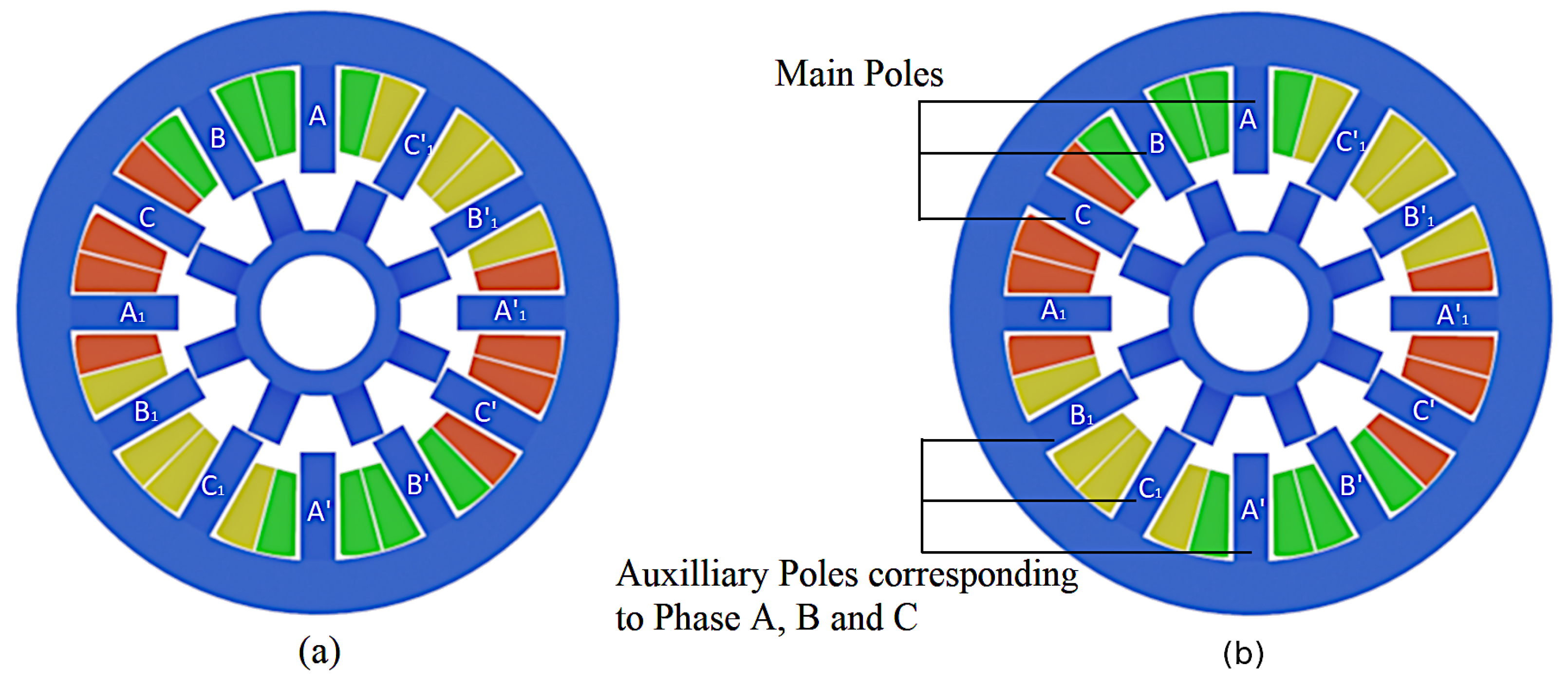
The machine topologies of conventional SRM and the proposed HESRM without PMs are shown in
Figure 1. Both motors have twelve stator and eight rotor poles without any PMs incorporated within the cores. Still, the windings of poles per phase are assigned for different excitation—main pole windings and auxiliary winding excitations, respectively, for the assigned poles. The new hybrid excitation technique’s main goal is to boost the conventional SRM’s torque performance without sacrificing any of its distinctive characteristics. Permanent magnets and structural changes are entirely avoided in HESRM. The excitation of the conventional SRM differs in that the windings are excited and separated separately to inject more external current into the HESRM. These auxiliary windings are selected so that two windings from each phase are separated, maintaining the motor’s mechanical and electrical symmetry.
Figure 1 depicts these alternately positioned auxiliary windings, which inject external DC current in accordance with the torque required by the controller. The motors’ measured speed is sensed and fed back to create PWMs, which are then delivered to the throttle.
First, the poles are assigned for auxiliary excitation. The stator of the HESRM differs from that of the conventional SRM; in the HESRM, the stator poles are assigned to the main and auxiliary poles based on the excitation. Since there are twelve stator poles in the motor, six poles can be used for the primary excitation, while the remaining poles can be used for the auxiliary excitation to provide the same three phases as conventional SRMs. Second, the number of poles for the primary and auxiliary windings is maintained constant in order to inject external flux into the poles simultaneously with the excitation of the primary windings. Separate DC excitation can increase the resultant flux in the air gap due to the symmetrical nature of the poles. Using electrical and mechanical symmetry, the primary and secondary poles are differentiated. This geometry of twelve stators can be utilized effectively to provide two distinct windings for each phase [
30]. There are two distinct windings in HESRM: the main windings and the auxiliary windings. With the aid of a separately excited driver circuit, the auxiliary windings’ poles inject DC current. The main windings provide the current for excitation of the motor. Because the variations in both windings’ currents affect the air-gap flux density, the flux in HESRM is more than the traditional SRM. The new topology has a greater flux density, power, and torque without using the PM behavior.
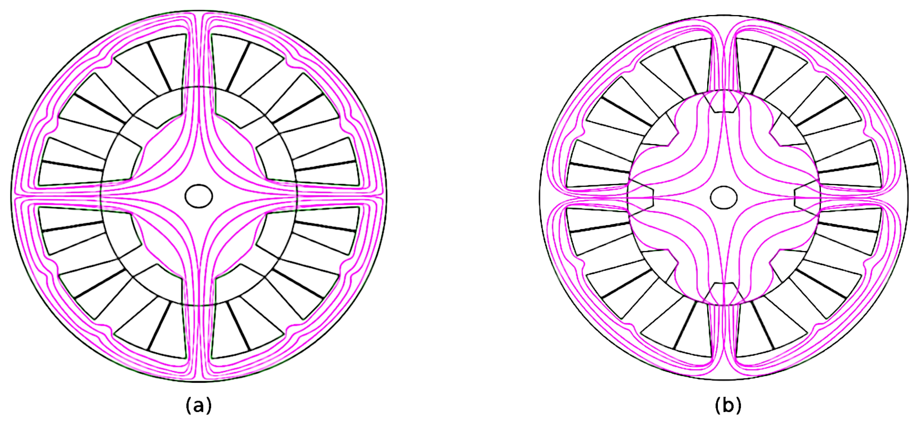
Figure 2 is a structural diagram of magnetic field distribution that illustrates the fundamental operating principle of the proposed HESRM without PMs. It shows the magnetic field distribution of two SRMs with aligned and misaligned poles. Regardless of whether the SRMs are operating in an aligned or unaligned position, identical field lines can be observed. The HESRM flux is injected along the same path as the carryover path for the primary winding flux. Therefore, the flux due to auxiliary excitation can carry a greater flux to generate a greater electromagnetic torque. A detailed block diagram of the HESRM is shown in
Figure 3. The new hybrid excitation technique’s main goal is to boost the conventional SRM’s torque performance without sacrificing any of its distinctive characteristics. Permanent magnets and structural changes are entirely avoided in HESRM. The excitation of the conventional SRM differs in that the windings are excited and separated separately to inject more external current into the HESRM. These auxiliary windings are selected so that two windings from each phase are separated, maintaining the motor’s mechanical and electrical symmetry.
The net flux generated by HESRM in the absence of PMs travels through the core and then the air gap, creating a closed path similar to the conventional flux path. When both coils are excited, the flux intensity generated by the primary and secondary differs because the secondary pole can carry a greater current than the primary. The total flux produced by the primary coil and the auxiliary coils can be observed to be added. Consequently, the total magnetic flux produced by the HESRM is greater than the conventional flux without PMs. Consequently, the electromagnetic torque results from the algebraic sum of the total effective flux of both windings.
The dimensions and specifications of the conventional SRM and the proposed HESRM are listed in
Table 1. Similarly, the number of phases, number of poles in the stator and rotor, rated power, speed, length of the core, and type of material are all identical. In addition, the assignment of the HESRM’s auxiliary and primary poles differs based on the flux path.
3. Characteristics of the Proposed HESRM Using 2D FEA Analysis
This section presents the magnetic characteristics of the conventional SRM at aligned and unaligned positions. To obtain better clarity and easiness of comparison, both the SRMs are given the same size, number of coils per pole, and similar types of windings, as shown in
Table 1. The field lines where the stator and rotor iron have the shortest flux path are concentrated in the aligned position rather than the unaligned one.
3.1. Magnetic Characteristics of Two SRM’s
The cross-sectional areas of the two SRMs are the same due to the same rotor construction and geometric dimensions. Thus, both SRMs, the stators, and rotor iron weights identical to the constructions have a 7.933 (kg) total net weight, and the stator and rotor core steel consumptions (kg) are 7.05683 and 2.6735, respectively. Owing to the difference, only the excitation scheme provided the winding with different currents.
Field Line and Flux Distributions
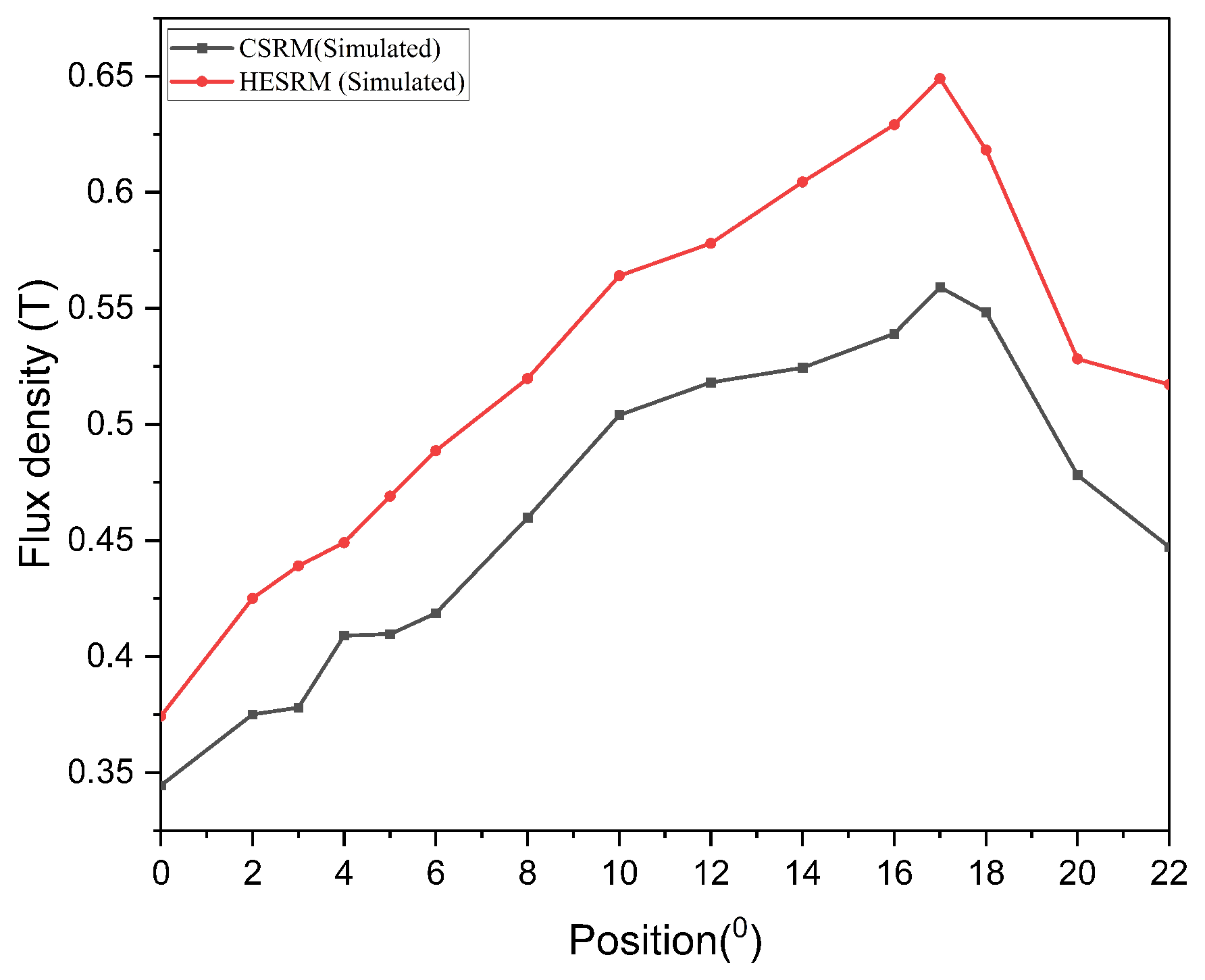
The magnetic characteristics of the proposed SRM are similar to that of the conventional SRM. Here, the quantity of the flux lines will increase as more current is injected into the auxiliary poles. As a result, the effective flux lines in the air gap increase, and the resultant electromagnetic torque increases.
Figure 4 and
Figure 5 demonstrate the magnetic flux distribution and the flux density of the conventional SRM and the proposed HESRM, respectively. The excitation for the three-phase scheme for the conventional SRM with aligned and unaligned poles shows that the minimum flux density is 1.2–1.3 Tesla (T) for the unaligned pole and 1.7–1.8 T for aligned poles. The conventional SRM’s range for maximum flux density is 0–1.9 T, and steel is the material used for the simulation.
Figure 6 shows the conventional SRM for the given excitation (5A) at aligned and unaligned positions. At aligned position, it is 1.2 T, and at unaligned position, it is 1.6 T. Because the auxiliary windings’ unexcited pole is aligned with the excitation pole in the HESRM, it can reach 1.06 T in alignment with the same excitation current (5A). Auxiliary injection current helps to increase the magnetic flux density in an unaligned state in 1.3 T, comparing the magnetic flux distribution and flux intensity of the proposed HESRM, where both characteristics are identical. Accordingly, there is only one difference in the intensity of flux carrying in the air gap due to different DC injections in the auxiliary poles. First, the excited state produces the main flux with the effect of the main winding, and the extra DC provided by the auxiliary excitation creates more electromagnetic torque.
The reluctance principle governs SRM. Therefore, the SRM generates the torque based on the magnetic reluctance of the motor. The magnetic circuit between the rotor and stator is very reluctant when they are not in alignment. As the rotor tries to align with the powered stator poles at this point, the stator pole pairs are activated, reducing the magnetic reluctance. Reluctance torque is formed when the rotor is able to reach the minimal point of reluctance. It is necessary to precisely time the stator poles’ excitation so that it only happens when the rotor is attempting to align with the exciting pole. SRM may require positive feedback from encoders or Hall effect sensors in order to control the excitation of the stator based on a precise rotor position.
3.2. Steady-State Characteristics
The electromagnetic behaviour of the proposed HESRM was analyzed through the FEM (finite element method) using commercial software ANSYS/Maxwell. The motor drive simulation was carried out by MATLAB/Simulink, and the interpretation was held by the co-simulation method. For this purpose, the feasibility of the proof of concept was verified with the help of software simulations by analyzing steady-state and dynamic behaviors.
Static Electromagnetic Torque
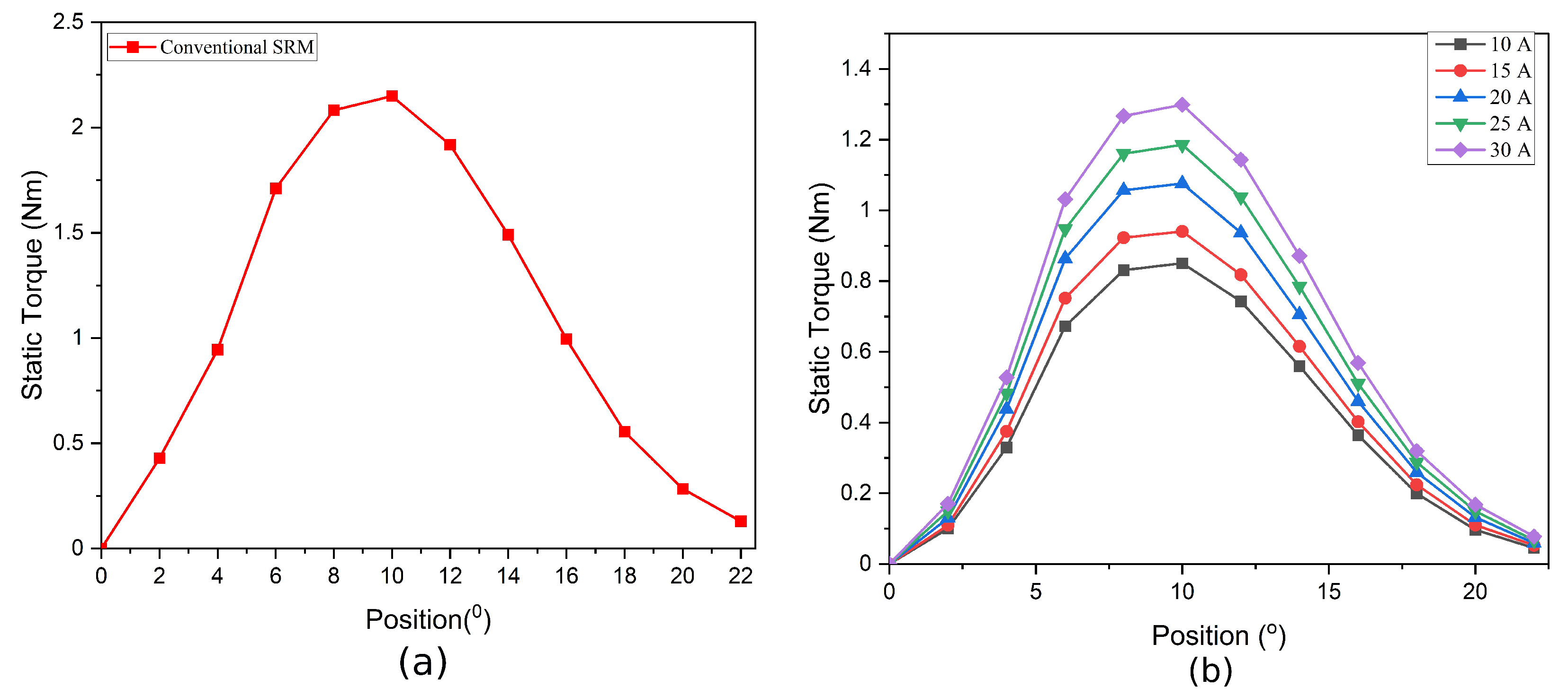
The static magnetic torque characteristics of two SRMs with phase excitations are shown in
Figure 7. The conventional SRM static torque curves with the current of 15 A vary from 0 to 22.5 degrees, as shown in
Figure 7a. Accordingly, the static torque for one-half of the excitation cycle of conventional SRM attains unalignment to the aligned pole. It can be seen that the torque varies from minimum to maximum and finally reaches a minimum with the unaligned position. The maximum static torque that produces the phase excitation current of 15 A is 2 N m. From the comparison, it is clear that the auxiliary excitation in which a different current is provided with the help of DC injection may attain different patterns of static currents. The auxiliary winding has a provision for carrying the maximum current to the rated value.
Figure 7b shows that the static flux curve pattern increases the effect of varying according to the rises of DC in the auxiliary coils. Since additional current is passed through DC injection in auxiliary windings using special circuitry, the flux inside the core increases, which results in higher torque and power density.
3.3. Dynamic Performance of Two SRM Drives
MATLAB/Simulink was used to study the performance of the motor drive system for two SRMs. The proposed HESRM drive system’s Simulink model has an asymmetric half-bridge converter, logic PWM, angle controller mechanical systems, DC sources, speed and current controllers, a separate auxiliary excitation with an extra switch, etc. The machine model is developed on the Ansys/Maxwell workbench. The dynamic performance of both machines was performed and compared under the same conditions.
3.3.1. Gate Pulse Characteristics of Two SRMs
Figure 8 shows the moving torque and current characteristics of two SRMs in which the gate pulses are given to the phases at the same turn ON and turn OFF times. In conventional SRM, the single PWM pulses sequentially provide the switching scheme for all phases. The hybrid excitation method provides identical gate pulses to the main and auxiliary windings separately. The torque characteristics of conventional SRM can be achieved with similar excitations in HESRM. Since the moving torque remains similar, the auxiliary current can be further increased to the rated value to achieve maximum performance.
3.3.2. Closed-Loop Current Control of Two SRMs
The closed-loop current control of the conventional SRM is established by obtaining current feedback from the windings and providing input to the current controller. The conventional and proposed HESRM showed similar results at various input currents with matching moving torque and slightly less ripple, as shown in
Figure 9. The current from the windings can be sensed and used to provide additional flux through the auxiliary in this hybrid excitation method.
3.3.3. Variable-Speed Control Strategy for Two SRMs
In
Figure 10, the speed control is established using a proportional–integral (PI) controller by measuring the actual speed and comparing it with the reference speed, which varies continuously from minimum to rated value. The proportional (
) and integral (
) values of the controller are tuned in such a way as to reach the set points as early as possible. The analysis of the two results shows similar characteristics at the same current rating and load. The additional torque needed for the motor can be identified and provided through these auxiliary windings to obtain better results. However, the HESRM method is derived to enhance the performance by separately injecting the DC with the help of auxiliary winding. Hence, these results elaborate on how to achieve the same performance through the different winding excitations separately. However, the HESRM makes it possible only through different currents passing through the assigned winding. This method benefits by changing different currents through the controller to improve the average torque characteristics and reduce the torque ripple to the minimum level.
In a conventional SRM, the variable speed is related to the main current excitation and torque, whereas in a HESRM, where there are two currents—the main current and an auxiliary current—the main current is responsible for both the excitations, and the auxiliary speed current is responsible for the variable speed.
Figure 10 displays the torque and current characteristics of the traditional and hybrid SRM at variable speeds. To simulate how EVs would operate in real time, the speed input is changed using ramps and steps. Steps of 1000 rpm are used to ramp up the speed from zero to 2500 rpm. The graphs show all three phases of the currents at various speeds. Since this motor is a three-phase switching machine, the irregularities in the phase currents are caused by the speed changes. The motor’s transient behavior is indicated by the longer switching patterns at the start of the operation.
6. Discussion
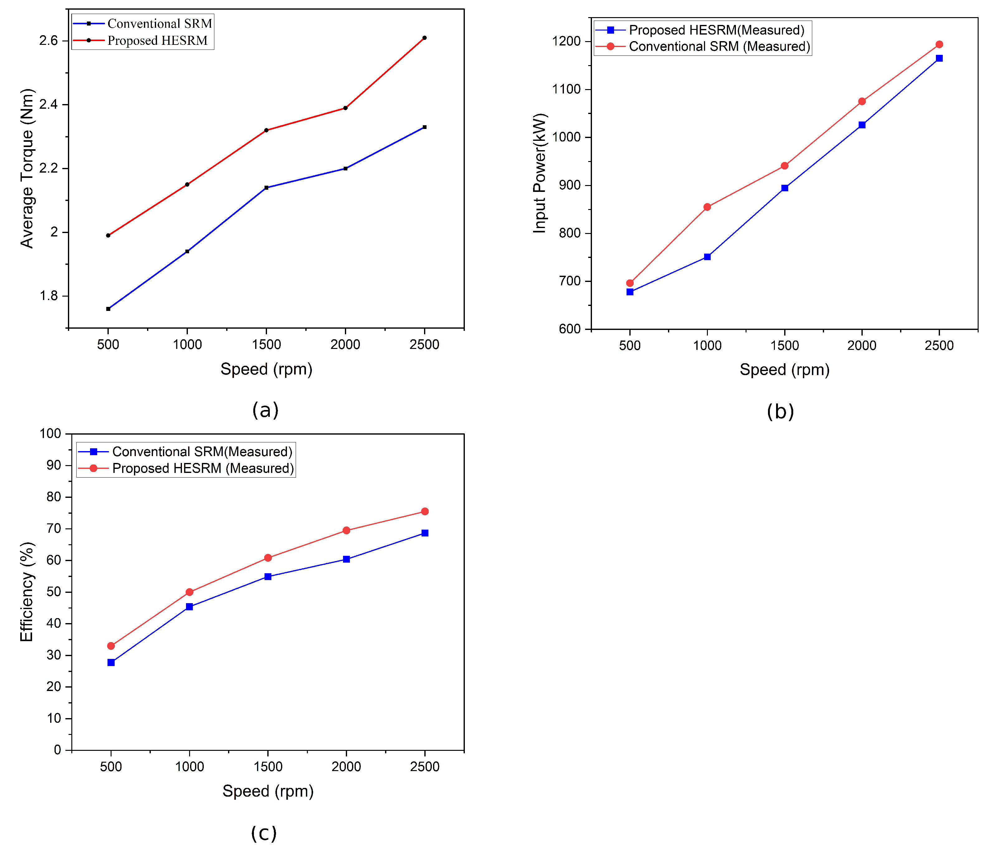
Figure 18a shows the plots of conventional and HESRM’s average torque characteristics for various speeds. Both have a difference of 1 to 2 N m at 500 rpm, and it gradually increases. The HESRM reaches almost 2.4 N m at 1500 rpm, whereas the conventional one is only 2.1 N m. The HESRM reaches a maximum torque of 2.6 N m at 2500 rpm with a lead of almost 0.3 N m.
The efficiencies for both SRMs were almost identical at the beginning of the test at 500 rpm. As speed increases, the efficiency of the HESRM makes clear leads compared with the conventional one. Up to 1500 rpm, the efficiencies of both motors follow a linear path with a difference of approximately 10%. At the rated speed of 2500 rpm, the efficiency of the motor differs to a maximum value of 80% and a minimum of 65%. The efficiency of the HESRM increased by 20%, as shown in
Figure 18b.
The input power consumed by both motors is almost constant at 500 rpm, as clearly seen in
Figure 18c. As the speed increases, the input power consumed by the motors starts to increase. The conventional SRM intakes more power at all the respective rpm compared with the proposed one. At 1000 rpm, the conventional SRM draws almost 850 W, whereas the HESRM draws a minimum of 700 W. At maximum speed, the input power consumed has a difference of almost 50 W.
Torque ripple is one of the major drawbacks of SRM, and thereby the hybrid excitation methods tend to provide higher possibilities. The proposed new HESRM without PM tends to exhibit less torque ripple than the conventional HESRM. In contrast, the conventional SRM exhibits a ripple of 3.72% at 2500 rpm, which decreases to 3.69% at 2000 rpm. Simultaneously, the proposed HESRM reduces torque ripple as a result of reduced pole switching, achieving 1.44% and 1.69% at 2500 and 2000 rpm, respectively.
7. Conclusions
When the average, static, and speed–torque characteristics of conventional and DC-injected hybrid SRMs are compared, it was found that significant improvements were made by HESRM over conventional SRM. In addition, the properties and performance of the machines are improved without sacrificing their fundamental qualities. In addition to a high torque-per-ampere rating, it offers high efficiency, high dependability, and redundancy. The standard SRM is outperformed by the proposed method, and it generates greater torque at significantly lower current levels. Furthermore, the proposed HESRM employs separate excitations for the windings, thereby enhancing the versatility of the controller.
The proposed topology may be a replacement for HESRM machines with PM insertion. Since this study clearly demonstrates enhanced performance, the proposed system can be implemented in a variety of applications, such as electric vehicles. Moreover, improved average and smooth speed–torque characteristics have been achieved, which can be an excellent solution for EVs. Finally, this new topology can achieve greater efficiency with reduced torque ripple. Future objectives of this research include the design and implementation of advanced, optimized controllers to further reduce torque ripples. We are planning to study variable-speed control strategies for SRMs along with new designs.


 ,
, 


