Abstract
This paper presents research conducted on the development of an innovative system to increase the amount of energy recovered from a high-speed kinetic energy storage based on a three-phase permanent magnet brushless (PM BLDC) motor/generator (mogen) with a flywheel-shaped rotor, compared to the efficiency obtained for standard solutions with power electronics systems. This kinetic energy storage is currently under development. In the system presented in the paper, the regulated DC output voltage of the 6T thyristor bridge is controlled with a tolerance within ±10% of the reference voltage for a variable power load. The input voltage of the rectifier is a three-phase trapezoidal-shaped voltage from the rotating mogen, whose amplitude can vary from 0 to 650 V and frequency from 0 to 250 Hz voltage. The article presents example results of simulation tests of the mogen-based kinetic energy storage model with the thyristors’ firing angle control system. As part of the research, a prototype of the rectifier was built on a laboratory scale, to confirm the validity of the assumptions regarding the synchronization and control method of the bridge using a new design of the thyristor gate drivers.
Keywords:
flywheel energy storage; Simulink; rectifier; 6T thyristor bridge; mogen; PM BLDC motor; hall sensor 1. Introduction
The aim of the work is to present the possibility of operation of a special version of a rectifier for recovering energy from a kinetic energy store. The output voltage from a magnet system based on a PM BLDC motor/generator (mogen) has the shape of a three-phase trapezoidal voltage. Previous solutions were based on motors and generators [1,2], PMSM and separate subassemblies of the inertia and motor/generator [1,2,3], while the solution presented in this article is both a motor/generator (mogen) and an inertia. This energy storage is made in an outrunner version with a rotating external part of the engine (similar to a bicycle wheel) [4]. The amount of stored energy varies from a certain maximum value (maximum value of voltage and frequency) to zero values, therefore the main purpose of the presented solution is to operate the rectifier for energy recovery in the largest possible range. A very important issue analyzed in the experimental part is to carry out tests in the field of rectifier synchronization specified in the patent [4], using Hall sensors’ pulses derived from the synchronization of the PM BLDC motor, and not, as in traditional solutions, with the use of synchronizing transformers. The solution with the use of hallotron pulses allows for a very precise transition of the trapezoidal voltage through zero, and importantly, this type of synchronization allows for precise operation in the range of low voltages and frequencies. This type of synchronization is not presented in the literature by other research centers because such solutions have not been implemented, which is also confirmed by the patent application in this field. The presented works are particularly important for future versions of kinetic energy storages based on hybrid composite inertia [5,6] that can operate at much higher rotational speeds of up to one hundred thousand revolutions [7].
Kinetic Energy Storage
Energy storage is currently a problem of increasing importance for every human being as well as for the whole of industrial civilization. The growing demand for energy resulting from the common use of increasingly complex devices and systems with greater total power consumption is forcing development and improvement of energy storage methods and technologies. In connection with attempts to reduce environmentally harmful toxic substances that are by-products of energy production from fossils fuels, renewable energy sources and technologies to store energy from these sources are gaining more and more popularity.
The main objectives of electric energy storage are as follows [8]:
- improved efficiency of power generation,
- improved management efficiency of energy production and transmission systems,
- improved power quality,
- better use of renewable energy sources [9],
- reliability of power supply (sources of additional energy, amount of stored energy),
- reducing costs of power outages,
- ensuring electricity supply.
Each of the electricity storage technologies has its advantages and disadvantages, depending on the place of use, the financial outlay incurred, as well as technological and material capabilities.
The division of different types of energy storage can be made due to [8]:
- duration of energy storage,
- hybrid storage units combining two different energy storage systems [10,11],
- amount of stored energy,
- speed of energy storage and recovery,
- type of technology used,
- number of cycles and depth of discharge,
- efficiency of the storage technology.
Figure 1 shows a comparison of different storage technologies based on rated power and discharge time. The longest discharge time at rated power have storages based on pumped storage hydropower (PSH) and compressed air storage (CAES). Considering the efficiency of energy storage technologies, flywheels (FES), lead–acid batteries, supercapacitors, and Li-ion battery-based storage are the best choices. Table 1 shows the assumed development goal of the Li-ion battery-based energy storage technology. Compared to the currently achieved parameters, there will be an increase in the density of stored energy, and reduction in weight and extended lifetime. The projected reduction in the cost of such storage from >1000 €/kWh to about 20 €/kWh or less is also of crucial importance.

Table 1.
Development goals of energy storage based on Li-ion batteries [12].
Table 1.
Development goals of energy storage based on Li-ion batteries [12].
| Type of Battery | Current Parameters | Targets for 2020–2030 | Target for 2050 |
|---|---|---|---|
| Li-ion for high-power applications |
|
|
|
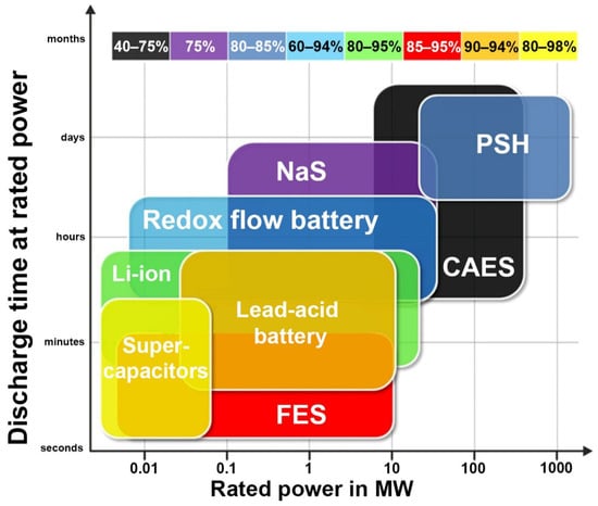
Figure 1.
Comparison of different energy storage technologies based on rated power and discharge time [13].
However, an important problem of the popular Li-ion storages in various versions is their disposal due to the harmful compounds they contain. This problem does not exist in the case of flywheel-based kinetic energy storages, that do not produce any by-products, making the solution fully ecological.
Considering the kinetic storages, one of the most promising solutions is a patented system based on a PM BLDC outrunner motor [4]. The efficiency of such a system is about 90–95% [14], and the cost of a complete 1 MWh storage with a 25-year lifetime is financially very attractive as shown in Figure 2.
This type of storage can be made in different versions, adapted to specified applications. Examples of possible applications could be forges, or foundries working at daytime, where the use of this type of storage will allow storing energy at night and recover it during the day. Another example could be the storage of energy obtained from renewable energy sources. In particular, the presented storage could be a solution to the problem of electric car charging. For example, Tesla cars are charged to drive 170 miles (273.5 km) in about 30 min using a super-fast charger (depending on the model—at an additional cost). In the case of the proposed solution with a PM BLDC motor, it will be possible to achieve the same in 5–7 min at no extra charge. The kinetic storage in this version can allow storage of up to 1 MWh with simultaneous recovery of the stored energy at 5 times the nominal power during charging. The research is based on a kinetic energy store, built on the basis of a PM BLDC motor with a rotating flywheel weighing approx. 4500 kg, and the main difference between other solutions and the analyzed one is that all three components constitute one device. This machine includes an engine, generator and flywheel which are all one device that can be described by the popular phrase “three in one”. This machine is closed in a vacuum chamber because of the losses due to the fan effect, which is the largest source of losses as opposed to all other losses combined [15]. A suitable vacuum level ensures that losses are brought to an acceptable level, and most of the remaining losses from bearing, winding, magneto and eddy current losses are removed from the vacuum chamber through a suitable cooling system.
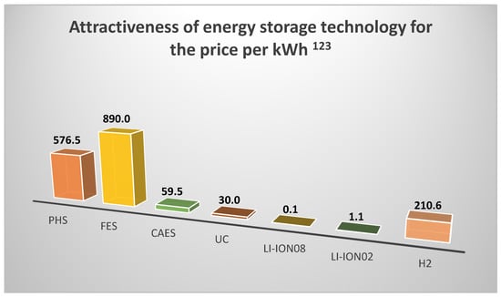
Figure 2.
Energy storage technology cost effectiveness index per kWh. 1 For LI-ION08 batteries, the number of cycles is less than 3000 for single batteries, while for a set of batteries it is even less [16]. 2 For kinetic energy storage, the number of cycles is 107 [17]. 3 Applies to systems without adiabatic transformation [18].
2. Energy Recovery Circuit of the Kinetic Storage with 6T Rectifier
Rectifiers used to regulate the output DC voltage [19] are most often supplied from AC voltage sources with the rms voltage varying within ±10% of the nominal value, and a fixed frequency, usually 50 Hz or 60 Hz, according to the standards used in the power industry.
The kinetic energy storage uses a conventional 6T thyristor rectifier PS supplied with 3 × 400 VAC (TRM), 50 Hz voltages UB1, UB2 and UB3, to supply power electronics commutator FS of the PM BLDC motor. As the voltage on the commutator bridge increases, the speed increases for the 100% PWM level and the flywheel storage acquires more and more kinetic energy. The BLDC mogen SP is located in the vacuum chamber to reduce the fan effect losses, which are the largest losses strongly dependent on the rotational speed.
The energy recovery circuit from the BLDC mogen (Figure 3) is also configured in a 6T arrangement, but this is the only common feature. The RMF rectifier circuit shown in Figure 3 is supplied with a three-phase trapezoidal voltage, whose amplitude and frequency vary from maximum values, in this case from 650 V and 250 Hz, to zero. The output voltage is regulated by changing the firing angle of the high-speed thyristors of the 6T bridge RMF. The constant output voltage of the RMF bridge is used to power the F50 inverter, which generates a three-phase voltage with a frequency of 50/60 Hz or can be used directly to supply constant voltage systems, e.g., electric cars. The entire operation of the kinetic energy storage is supervised by the superior control system. Due to the difficult operating conditions of the thyristors, they are triggered by special gate drivers that meet the condition dig/dt < 300 ns for the gate current rising slope. The presented structure of the kinetic energy storage system is used to locate the tested RMF bridge rectifier system in its surroundings, showing the high-current connections and control signals. As part of the simulation and some practical verification, a prototype of a rectifier bridge was used, built on the basis of the target assumptions for the RMF bridge. The basic change is the method of synchronization of the RMF rectifier bridge, consisting in the use of Hall effect pulses synchronizing the operation of the PM BLDC motor, and not, as in the previous systems, from the phase-to-phase or phase voltage.
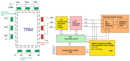
Figure 3.
Block diagram of the energy recovery circuit/subsystem, claimed in the patent [4].
The synchronization circuit also makes it possible to add an offset of the synchronizing pulses with respect to the voltage waveform of a given phase.
It should be noted that suitable control of the RMF rectifier (Figure 4), with the input voltage varying over its full operating range and the voltage frequency varying from some maximum to zero, that ensures maintaining constant output voltage for constantly varying load current is itself a rather complicated problem.
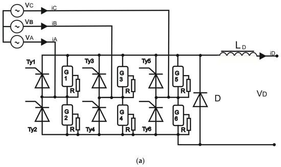
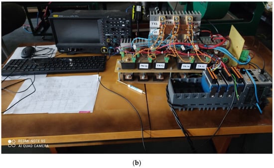
Figure 4.
(a) Diagram of the 6T rectifier bridge used in simulations. Phase-to-phase input voltages vab, vbc, vca are variable amplitude and frequency trapezoidal voltages from the BLDC mogen. (b) Photo of the prototype 6T rectifier setup.
For correct and stable operation, the requirements imposed on all power electronics components in both the energy charging and recovery paths are very high [20]. Taking into account high input voltage and current, a particularly important issue is the correct triggering of the rectifier thyristors for the 300 Hz rectifier, the frequency that may occur for high-speed operation of the flywheel BLDC storage.
The 6T rectifier output voltage [9] is:
where:
Vmax—bridge input peak phase voltage.
Taking into account the inductance in the output DC circuit, the output voltage is related to the input voltage frequency in the following way [9]:
Given that the virtual resistance (reactance) is equal to [9]:
the output voltage can be written as follows [9]:
where:
3ωLDC/π,
- Vinp-p—input phase-to-phase voltage of the bridge;
- iout—output current of the RMF bridge;
- α—thyristors’ firing angle;
- f—input voltage frequency;
- LDC—DC output circuit inductance.
A proportional-integral-differential (PID) controller with output saturation is used in simulations (Section 3) to control the firing angle of the thyristors. Simulations were carried out for different frequencies of the input bridge voltage (different rotational speeds of the flywheel).
The structure of the PID controller consists of three parts [21]:
- ▪ proportional,
- ▪ integral,
- ▪ derivative,
3. Simulation Research
The purpose of the simulation research was to analyze operation of the 6T thyristor bridge control system in the energy recovery circuit of the flywheel energy storage. The task of the bridge control system is to stabilize the output voltage, which supplies a varying resistive load, by changing the thyristors’ firing angle. There are numerous modeling and simulation studies of a flywheel-based energy storage systems in the literature, but only few deal with the constant DC voltage requirement at the storage discharge stage. A similar problem of the discharge control strategy with load current and rotor speed compensation is considered, e.g., in [22], for a PMSM/generator and 6T transistor bridge. The subject of [23] is control of a hybrid energy storage in a shipboard medium-voltage DC system to provide backup power or buffer load changes.
The simulation results presented in the paper deal, in particular, with:
- how long the flywheel storage can stabilize the output DC voltage for a constant load power (time of changing the thyristors’ firing angle α from 60° to 0°) starting from a given initial rotational speed of the flywheel,
- percentage of the initial kinetic energy E0kin converted into electric energy Eload supplied to the load during the period of the load power stabilization,
- dynamic response of the proposed control system to the step change in the output voltage reference Vload_ref and to the step change in the load power.
3.1. Simulation Model of the Energy Recovery Subsystem
The simulations were carried out in the MATLAB/Simulink environment using blocks from the Simscape Electrical toolbox [24]. The model of the flywheel energy recovery circuit in the form of a Simulink block diagram is shown in Figure 5.
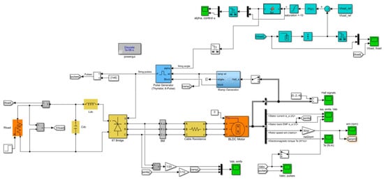
Figure 5.
Simulink model of the flywheel energy storage energy recovery subsystem with BLDC motor, 6T thyristor rectifier and the load voltage control system.
The Simscape physical components of the energy recovery circuit shown in Figure 5 are:
- three-phase BLDC motor (operating in the energy generation mode) with the flywheel rotor
- three-phase rectifier: 6T thyristor bridge (the electrical diagram of the bridge is presented in Figure 4),
- passive components of the DC load circuit: inductance, capacitance and variable resistance.
The DC load voltage control system with the discrete-time PI controller, ramp generator and 6T pulse generator constitutes the signal part of the model.
The BLDC motor block is based on the following dynamical equations of a three-phase permanent magnet brushless DC motor with trapezoidal back electromotive force waveforms [24,25,26,27]:
where:
- Rs—resistance of the stator windings,
- Ls—inductance of the stator windings,
- ia, ib, ic—phase currents,
- , , —phase electromotive forces (EMFs), in per-unit value to the amplitude of the flux λ,
- vab, vbc—phase-to-phase voltages,
- ωm—rotational velocity of the rotor,
- λ—amplitude of the flux induced by the permanent magnets of the rotor in the stator phases,
- p—number of pole pairs,
- Te—electromagnetic torque.
The model parameters used in simulations are specified in Table 2.

Table 2.
Parameters of the energy recovery subsystem simulation model.
Simulations are started with a specified initial rotational speed ω0 of the flywheel (BLDC mogen rotor), i.e., the maximum kinetic energy. During the storage discharge, the BLDC motor decelerates and both the frequency and the amplitude of its output three-phase voltage gradually decrease. The goal of the control system is to stabilize the rectifier output voltage Vload at a given constant reference level Vload_ref by regulating the bridge thyristors’ firing angle α. For a given initial speed ω0 and load resistance Rload, the value of Vload_ref is chosen such that the initial angle α ≈ 60° (upper stabilization limit) and during the energy recovery run (the storage “discharge”) the angle is gradually decreased to zero (lower stabilization limit). The value of Vload_ref that allows observation of this maximum control range is approximately proportional to the initial rotational speed ω0.
In this article, there are presented results obtained for a simple discrete-time PI controller with the load voltage Vload feedback. The discrete-time transfer function of the controller is [24]:
where: kP—proportional gain, kI—integral gain, Tsc—control update period. In the presented simulations, it was assumed to be 20 ms (50 times per second). The actual 6T bridge control is designed such that the firing angle is determined on the basis of the digital controller output which varies from −10 to +10 V. In the simulation, the −10 to +10 V range is mapped linearly onto the 60° to 0° range of α. Since the control error is proportional to reference Vload_ref, the proportional gain kP must be proportionally reduced with growth of Vload_ref.
The simulations were carried out for high target rotational speeds of the presented storage. For example, ω0 = 10,000 rpm gives initial frequency of the BLDC voltage of about 1000 Hz so in order to model the voltage/current waveforms and short thyristor firing pulses correctly, the fundamental simulation step was set to Ts = 5 µs. The ramp generator block produces the variable-slope ramp signal ωt for the pulse generator block. It is actually a staircase signal obtained by periodic counting of synchronizing rising slopes from a single-phase Hall sensor. The slope (frequency ω) for the next period is determined from the count in the previous step which introduces a delay.
3.2. Simulation Results and Discussion
The results of the energy recovery simulation for the initial flywheel rotational speed ω0 = 5000 rpm and a constant load are shown in Figure 6. To observe the full range of the firing angle, the reference voltage was set to Vload_ref = 200 V. The load voltage is stabilized well over period τ ≈ 650 s when the firing angle decreases from α = 60° to α = 0°. The electric power supplied to the load over this time is Pload = Vload2/ Rload ≈ 80 kW and the total supplied energy Eload = Ploadτ ≈ 14.4 kWh which is about 70% of the initial kinetic energy of the flywheel E0kin = Jω02/2 ≈ 20.1 kWh. After the firing angle reaches zero (the controller output saturates), the load voltage and current quickly decrease. It was observed that setting the controller proportional gain kP too high results in oscillations of the firing angle and increased pulsation of the load voltage.
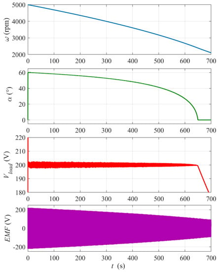
Figure 6.
Simulation results for the flywheel energy recovery run with ω0 = 5000 rpm and constant Rload = 0.5 Ω. Reference voltage Vload_ref = 200 V. The bottom plot shows the envelope of the BLDC mogen phase electromotive force EMF . PI controller settings: proportional gain kP = 0.03, integral gain kI = 1.
Figure 7 shows a zoomed-in view of the output DC voltage Vload waveform from Figure 6 at time t = 100 s and t = 600 s. One can see that the mean value of the voltage is stabilized well both at the beginning and at the end of the run. The amplitude of the voltage rippling (its frequency is proportional to the rotational speed) is clearly below the allowable level.
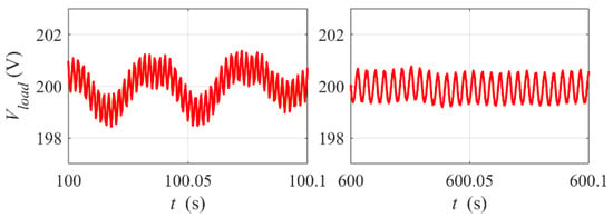
Figure 7.
Rippling of the load voltage. Zoomed-in view of Vload waveform from Figure 6 at time t = 100 s and t = 600 s.
Figure 8, Figure 9 and Figure 10 show details of the of the energy recovery system dynamic response at the thyristor bridge start-up and to the step change in the reference output voltage Vload_ref.
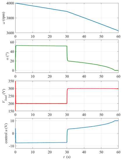
Figure 8.
Dynamic response of the system at the thyristor rectifier start-up t = 0 and to the step change in the reference output voltage Vload_ref from 200 V to 300 V at time tstep = 30 s. Load resistance Rload = 0.5 Ω, initial rotational speed ω0 = 4000 rpm, PI controller settings: kP = 0.03, kI = 1.
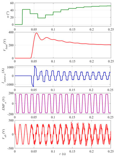
Figure 9.
Start-up of the rectifier. Zoomed-in view of waveforms from Figure 8. The digital control update period Tsc = 20 ms. Note two-control-period (40 ms) delay of the start of the rectifier pulsing and the stator current.
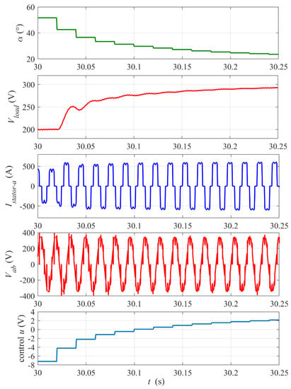
Figure 10.
Dynamic response of the system to the step change in the reference output voltage Vload_ref from 200 V to 300 V at time tstep = 30 s. Zoomed-in view of waveforms from Figure 8. The digital control update period Tsc= 20 ms.
At the start-up (see zoomed-in plots in Figure 9), the rectifier control rapidly increases the firing angle α to limit and stabilize the output voltage Vload at the reference value Vload_ref = 200 V. Note that the digital control, updated every Tsc = 20 ms, introduces a delay because a value of firing angle calculated in one control step is implemented by the thyristors’ drivers over the next step. It is visible in waveforms of Vload, the BLDC mogen stator current Istator and impulses on the output phase-to-phase voltage Vab in Figure 9. This control delay is the main reason for the initial overshoot of Vload and its relatively slow return to the reference level. Nevertheless, the settling time of about 0.2 s meets requirements of the project. The peaks on the Vab waveform occur at the thyristors’ switching instants (six per period). The amplitude and frequency of the back electromotive force EMF trapezoidal waveform are proportional to the rotational velocity of the rotor.
Figure 10 presents a zoomed-in view of the system response to the step change in reference Vload_ref at t = 30 s from Figure 8 In this case, the transient steps of the firing angle are smoother, because the controller does not start from zero, and the voltage response does not exhibit an overshoot. The control dynamics looks slow due to conservative (low) setting of the controller proportional gain kP to avoid oscillations of the firing angle, but the settling time of about 0.2 s meets requirements.
Figure 11 shows the response of the system to the step of the load power (step of the disturbance). The change in the load results in a momentary peak of the voltage and proportional drop of the load current. The deceleration of the flywheel for the smaller load after the step power is clearly slower.
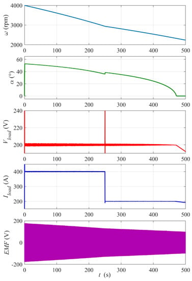
Figure 11.
Response of the system to the step change in the load power from 80 kW (Rload = 0.5 Ω) to 40 kW (Rload = 1 Ω) at time tstep = 250 s. Reference voltage Vload_ref = 200 V, initial rotational speed ω0= 4000 rpm, PI controller settings: kP = 0.03, kI = 1.
A zoomed-in view of the waveforms from Figure 11 and the control signal around the step instant is presented in Figure 12 (the envelope of the EMF is replaced with the mogen phase-to-phase voltage Vab waveform). The step of the load results in peak deviation followed by decaying oscillations of Vload. For the chosen controller settings, the voltage settling time is about 0.15 s and the voltage stabilization is very good. The control response and the firing angle are delayed as was explained earlier and, in consequence, the voltage oscillations cannot be fully removed.
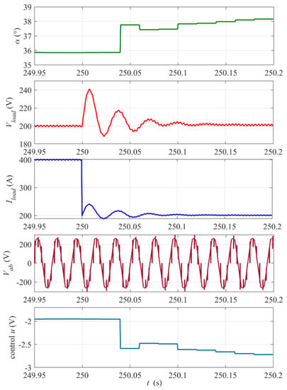
Figure 12.
Zoomed-in view of waveforms from Figure 11 around the step instant tstep = 250. The digital control update period Tsc= 20 ms.
Figure 13 shows plots of the energy recovery run for the higher initial flywheel rotational speed ω0 = 10,000 rpm. In this case, the full range of the firing angle changes can be observed for the set reference voltage Vload_ref = 370 V. Note that, until time t ≈ 40 s, the control is saturated at α = 60° and the load voltage decreases from above the reference value. Then, the control stabilizes the voltage for about 730 s. Finally, the control reaches α = 0° and the voltage drops below the reference. The electric power supplied to the load over the stabilization period is Pload ≈ 274 kW (a load power much higher than the nominal power was admitted in simulations to shorten the simulation time due to the computer memory limitations) and the total supplied energy Eload ≈ 55.6 kWh which is, as shown previously, about 70% of the initial kinetic energy of the flywheel E0kin ≈ 80.3 kWh. The controller proportional gain kP is half that in the previous case because the reference Vload_ref is almost twice as high.
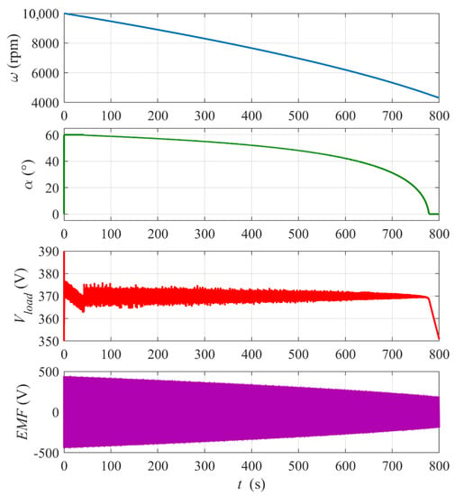
Figure 13.
Simulation results for the flywheel energy recovery run with ω0 = 10,000 rpm and constant Rload = 0.5 Ω. Reference voltage Vload_ref = 370 V. PI controller settings: kP = 0.015, kI = 0.5.
4. Experimental Results
As a result of the simulations, experimental tests were also carried out in order to confirm the adopted theoretical assumptions regarding the signals controlling the experimental rectifier bridge presented in Figure 4. For the correct operation of the thyristor gate signals and the entire rectifier, the values of the current gain of the gate pulses below 300 ns have been adopted, which should meet the most critical conditions for thyristor triggering [28]. These dependencies are mutually related, therefore they should be experimentally verified, which is confirmed by the following waveforms recorded with an oscilloscope. Figure 14 shows an oscillogram of the 260 ns dig/dt gate pulse ensuring efficient and very fast switching of the entire thyristor structure for 300 Hz. Such fast switching results in low losses and keeps the temperature of the thyristor structure as low as possible, which is an important condition of stable and long-term operation of the thyristors, especially for trapezoidal voltage waveforms.
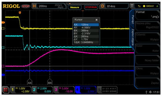
Figure 14.
Oscillogram of the 260 ns gate pulse rising slope dig/dt.
This thyristor triggering controller provides the right current and voltage for any, even the worst, operating conditions, as well as double galvanic isolation between the control circuit and the thyristor supply voltage. The configuration and specific conditions of the rectifier operation as well as the synchronization circuits that meet very precise matching of zero-crossing of synchronization signals were patented. An oscillogram of these signals is shown in Figure 15, where channels 1 and 2 show the voltage and the current, respectively, channel 3 shows the synchronization signal for one of the phases of the mogen output voltage and channel 4 shows the phase-to-phase voltage.
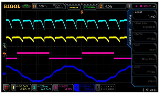
Figure 15.
Current, voltage, synchronization signal and phase-to-phase voltage waveforms in the RMF rectifier.
Figure 16 shows the synchronization signals for one of the phases (channel 1), the control signals for thyristor gate drivers (channel 4) and intermediate waveforms (channel 2,3) occurring in the control circuit of the prototype controller of the energy recovery circuit RMF rectifier.
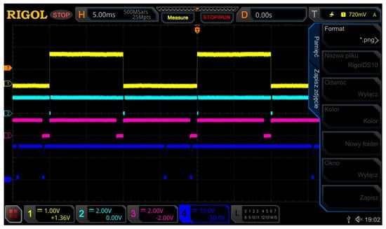
Figure 16.
Synchronization signals of the RMF rectifier in the energy recovery circuit.
The oscillograms shown in Figure 14, Figure 15 and Figure 16 were recorded on a prototype rectifier bridge built on the basis of fast inverter thyristor tq < 40 ns and proprietary gate controllers meeting the assumed parameters dig/dt < 300 ns. All measurements were made with the RIGOL MSO5204 oscilloscope, also with the use of PVP 2350 measuring probes and the MA200 current and voltage DP 50 probe. The circuit of the bridge and gate drivers will be presented in more detail in the following articles, devoted to a greater extent to the experimental (practical) verification, but to a greater extent to the RMF bridge control system powered by trapezoidal voltage with variable voltage and frequency.
5. Comparisons
The adopted simulation assumptions and experimental results confirm the rectifier’s responses to any excitations in accordance with the PID controller in terms of fast forcing changes, as well as a full and stable range of rectified trapezoidal voltage based on Hall effect synchronizing pulses, especially in the vicinity of the voltage crossing rectified by zero.
6. Conclusions
The proposed control of the flywheel storage energy recovery rectifier is a simple but effective solution as was shown in the presented simulations. It stabilizes the rectifier output voltage for a wide range of the rectifier input voltage amplitude and frequency as well as for rapid changes in the load power or the reference load voltage. The presented simple system of energy recovery from the BLDC mogen-based flywheel with a thyristor rectifier allows recovery of about 70% of the initial kinetic energy during the voltage stabilization period, which is a satisfactory fraction. In the present version, the load voltage reference is set “manually” to avoid control saturation over the full range of the thyristors’ firing angle. The control will be developed further towards a sort of gain scheduling that would adjust the voltage reference for several intervals of the flywheel rotational velocity. This problem, as well as optimization of the controller settings, will be the subject of future research. In the meantime, the control will be implemented and tested on the laboratory scale with the BLDC mogen flywheel for lower rotational velocities until the problems with keeping near vacuum pressure in the flywheel housing are solved.
Author Contributions
Conceptualization, P.G. and Z.G.; Formal analysis, Z.G. and J.B.; Investigation, P.G. and Z.G.; Methodology, P.G.; Software, J.B.; Validation, Z.G.; Visualization, J.B.; Writing—original draft, P.G.; Writing—review & editing, J.B. All authors have read and agreed to the published version of the manuscript.
Funding
This research received no external funding.
Data Availability Statement
Not applicable.
Conflicts of Interest
The authors declare no conflict of interest.
Abbreviations
The following abbreviations are used in this manuscript:
| CAES | Compressed air energy storage |
| FES | Flywheel energy storage |
| H2 | Hydrogen energy storage |
| IGBT | Insulated gate bipolar transistor |
| LI-ION08 | Li-on battery discharged at 80% of its capacity |
| LI-ION02 | Li-on battery discharged at 20% of its capacity |
| Mogen | Permanent magnet brushless motor/generator |
| NaS | Sodium–sulfur batteries |
| PM BLDC | Pulse modulation brushless direct current |
| PMSM | Permanent magnet synchronous motor |
| PWM | Pulse width modulation |
| PSH | Pumped storage hydropower |
| RMF | Medium-frequency rectifier |
| UC | Ultracapacitors |
References
- Li, X.; Palazzolo, A. A review of flywheel energy storage systems: State of the art and opportunities. J. Energy Storage 2022, 46, 103576. [Google Scholar] [CrossRef]
- Olabi, A.G.; Wilberforce, T.; Abdelkareem, M.A.; Ramadan, M. Critical Review of Flywheel Energy Storage System. Energies 2021, 14, 2159. [Google Scholar] [CrossRef]
- Elbouchikhi, E.; Amirat, Y.; Feld, G.; Benbouzid, M.; Zhou, Z. A Lab-scale Flywheel Energy Storage System: Control Strategy and Domestic Applications. Energies 2020, 13, 653. [Google Scholar] [CrossRef]
- Galuszkiewicz, Z.; Sutkowski, M. System Przetwarzania, Magazynowania i Zwrotu Energii Elektrycznej KAPS. Polish Patent No. 225294, 20 September 2016. [Google Scholar]
- Han, Y.; Ren, Z.; Tong, Y. General Design Method of Flywheel Rotor for Energy Storage System. Energy Procedia 2021, 16, 359–364. [Google Scholar] [CrossRef][Green Version]
- Mitali, J.; Dhinakaran, S.; Mohamad, A.A. Energy storage systems: A review. Energy Storage Sav. 2022, 1, 166–216. [Google Scholar] [CrossRef]
- Choudhury, S. Review of energy storage system technologies integration to microgrid: Types, control strategies, issues, and future prospects. J. Energy Storage 2022, 48, 103966. [Google Scholar] [CrossRef]
- Całus, D.; Gałuszkiewicz, Z.; Gałuszkiewicz, P. Porównanie Systemów Magazynowania Energii Elektrycznej—ProEnergo—Możliwości i Horyzonty Ekoinnowacyjności—Energetyka Odnawialna i Magazynowanie Energii; Instytut Naukowo-Wydawniczy “Spatium”: Radom, Poland, 2016; pp. 10–24. [Google Scholar]
- Rashid, M.H. Power Electronics Handbook, 3rd ed.; Butterworth-Heinemann is an Imprint of Elsevier: Burlington, MA, USA, 2011. [Google Scholar]
- Lai, C.S.; Locatelli, G.; Pimm, A.; Wu, X.; Lai, L.L. A review on long-term electrical power system modeling with energy storage. J. Clean. Prod. 2021, 280, 124298. [Google Scholar] [CrossRef]
- Taraft, S.; Rekioua, D.; Aouzellag, D. Wind Power Control System Associated to the Flywheel Energy Storage System Connected to the Grid. Energy Procedia 2013, 36, 1147–1157. [Google Scholar] [CrossRef]
- Martens, D. (Ed.) European Energy Storage Technology Development Roadmap towards 2030; European Association for Storage of Energy, European Energy Research Alliance. 2014. Available online: https://ease-storage.eu/wp-content/uploads/2015/10/EASE-EERA-recommendations-Roadmap-LR.pdf (accessed on 1 October 2022).
- IEA Analysis and EPRI (Electric Power Research Institute). Electrical Energy Storage Technology Options Report; EPRI: Palo Alto, CA, USA, 2010.
- Ruddell, A.J.; Schoennenbeck, G.S.; Jones, R.; Bleijs, J.A.M. Power Converters Flywheel Energy Storage Systems; Final Report of EU Project No JOR3-CT95-0070; European Commission: Brussels, Belgium, 1998. [Google Scholar]
- Šonský, J.; Tesař, V. Design of a stabilised flywheel unit for efficient energy storage. J. Energy Storage 2019, 24, 100765. [Google Scholar] [CrossRef]
- Hannan, M.A.; Wali, S.B.; Ker, P.J.; Rahman, M.S.A.; Mansor, M.; Ramachandaramurthy, V.K.; Muttaqi, K.M.; Mahlia, T.M.I.; Dong, Z.Y. Battery energy-storage system: A review of technologies, optimization objectives, constraints, approaches, and outstanding issues. J. Energy Storage 2021, 42, 103023. [Google Scholar] [CrossRef]
- Wicki, S.; Erik, G.; Hansen, B. Clean energy storage technology in the making: An innovation systems perspective on flywheel energy storage. J. Clean. Prod. 2017, 1562, 1118–1134. [Google Scholar] [CrossRef] [PubMed]
- Bazdar, E.; Sameti, M.; Nasiri, F.; Haghighat, F. Compressed air energy storage in integrated energy systems: A review. Renew. Sustain. Energy Rev. 2022, 167, 112701. [Google Scholar] [CrossRef]
- Barlik, R.; Nowak, M. Energoelektronika—Elementy, Podzespoły, Układy; Oficyna Wydawnicza Politechniki Warszawskiej: Warszawa, Poland, 2014. [Google Scholar]
- Koohi-Fayegh, S.; Rosen, M.A. A review of energy storage types, applications and recent developments. J. Energy Storage 2020, 27, 101047. [Google Scholar] [CrossRef]
- Wang, L. PID Control System Design and Automatic Tuning Using MATLAB/Simulink; Wiley-IEEE Press: Piscataway, NJ, USA, 2020. [Google Scholar]
- Zhang, X.; Yang, J. An improved discharge control strategy with load current and rotor speed compensation for high-speed flywheel energy storage system. In Proceedings of the 17th International Conference on Electrical Machines and Systems, Hangzhou, China, 22–25 October 2014; pp. 318–324. [Google Scholar]
- Chen, X.; Zhou, J.; Shi, M.; Yan, L.; Zuo, W.; Wen, J. A Novel Virtual Resistor and Capacitor Droop Control for HESS in Medium-Voltage DC System. IEEE Trans. Power Syst. 2019, 34, 2518–2527. [Google Scholar] [CrossRef]
- The Mathworks Inc. Simscape Electrical. Reference, R2022a; The Mathworks Inc.: Natick, MA, USA, 2022. [Google Scholar]
- Bose, B.K. Power Electronics and Motor Drives. Advances and Trends, 2nd ed.; Academic Press: London, UK, 2021. [Google Scholar]
- Khan, M.J.; Iqbal, M.T. Simplified modeling of rectifier-coupled brushless DC generators. In Proceedings of the 4th International Conference on Electrical and Computer Engineering, Dhaka, Bangladesh, 19–21 December 2006; pp. 349–352. [Google Scholar]
- Krause, P.C.; Wasynczuk, O.; Sudhoff, S.D. Analysis of Electric Machinery and Drive Systems; Wiley-IEEE Press: Piscataway, NJ, USA, 2013. [Google Scholar]
- Łastowiecki, J. Układy Pomiarowe Prądu w Energoelektronice; Centralny Ośrodek Szkolenia i Wydawnictw SEP: Warszawa, Poland, 2003. [Google Scholar]
Publisher’s Note: MDPI stays neutral with regard to jurisdictional claims in published maps and institutional affiliations. |
© 2022 by the authors. Licensee MDPI, Basel, Switzerland. This article is an open access article distributed under the terms and conditions of the Creative Commons Attribution (CC BY) license (https://creativecommons.org/licenses/by/4.0/).