1. Introduction
In Poland, the illumination of streets and roads during the year is provided in a natural way through the influence of the sun, both directly and indirectly (reflections from the sky and surrounding objects), in more than half of the time (approx. 4610 h). In the remaining time (i.e., 4150 h), streets and roads are illuminated with the use of artificial light sources, mainly from sources that use electricity [
1]. Several million road luminaires require greater or lesser intervention in order to increase the efficiency of lighting [
2]. Reducing electricity consumption related to lighting is one of the widely promoted savings in the electricity sector. The slogans about replacing discharge lighting with LED luminaires and achieving savings of up to 80% of the current energy consumption have become popular. The implementation of such investments is inherently connected with the use of modern control systems. All activities in this direction should be carried out in accordance with the provisions of EU and national law [
3,
4,
5,
6,
7,
8,
9].
Along with the growing use of new control technologies in power grid supply systems, there is a problem of maintaining the parameters required by the standards that define the quality of electricity [
3,
4]. The constantly growing number of non-linear receivers, also in lighting installations, causes increasing problems with voltage and current distortions. The current distortions are not only greater than those allowed by the current standards, but, in extreme cases, they are so large that they cause various types of failure. Many works present both the definition of the basic parameters, the quality of electricity and the methods of shaping the voltage and current waveforms [
10,
11] and the methods of reducing harmonics through the appropriate selection of filters and the impact of road luminaires on the power supply network [
12,
13,
14,
15]. Many authors also point out and present analyses of the economic and technical aspects of the replacement and modernization of existing light sources with LEDs, which are commonly regarded as the most energy-efficient [
16,
17,
18,
19].
The use of LED technology is considered by investors as a panacea for all problems. The expected goal of modernization is to reduce investment and operating costs. The lighting market uses regulators to reduce the emitted luminous flux of discharge sources. With an unused lighting infrastructure (cables, poles, luminaire heads), this only means the need to replace the sources and supplement the installation equipment with a regulator. The authors want to emphasize the advantages and disadvantages of controlling discharge sources and LEDs by comparing the effects of their work in real conditions, describing it in the following chapters of the article.
The rest of this article is organized as follows. The second chapter describes the problems of control and problems resulting from the use of control in street lighting containing luminaires with discharge sources. The authors’ opinions and actual measurements are from the work of such sources. The third chapter in the polemics to the second chapter presents the analyses and problems resulting from the operation of a road lighting installation containing only LED luminaires. The fourth chapter presents the currently functioning street lighting system after comprehensive modernization along with the lighting control system. The article ends with a summary in which the authors present conclusions.
2. Control of Lighting Fixtures with Discharge Sources
Since the beginning of the “LED revolution” in the road lighting industry, there has been a problem of whether to continue to use luminaires with discharge sources or with LED sources. Luminaires with discharge sources used so far are perceived as “obsolete” and require a complete replacement by luminaires with LED sources [
20,
21,
22]. In fact, they concern mercury and low pressure sodium sources. Luminaires with high-pressure sodium and metal halide sources will continue to be used in road lighting. Contrary to the prevailing, very positive opinions, LED technology has its drawbacks, which result, among others, from the functions of electronic systems (the light source itself—the LED chip and supporting systems). Luminaires with discharge sources also contain auxiliary systems. However, they are less complicated and therefore less prone to damage. They allow us to control the value of the emitted luminous flux, contrary to the common opinion that it is impossible.
The device supporting the work of light sources used in discharge fittings is called “control gear” [
23]. However, its name defines more functions than the previously known ballasts for discharge lamps. Pursuant to the provisions of the regulation [
23], “control gear” means one or more devices, which may or may not be physically integrated with a light source, designed to adapt the supply network to the electrical format required by one or more specific light sources within the boundary conditions dictated by electrical safety considerations and electromagnetic compatibility. The process may include converting the supply voltage and ignition voltage, limiting the operating and preheating current, preventing cold ignition, correcting the power factor or limiting radio interference. This means that the requirements for the energy efficiency of discharge luminaires must also be extended to their control systems.
One of the methods used to save electricity is the use of power reducers. This can be carried out in two ways. The first is by lowering the voltage value (transformer or transformerless systems based on semiconductor systems) and the second is by changing the frequency of the voltage supplying the light source.
A power supply with high-quality parameters is the basic factor that allows for the rational management of electricity. The applied transformerless systems save electricity used by lighting through a controlled voltage reduction. The introduction to the use of transformerless power reducers also means a lower consumption of light sources and lighting fixtures due to lower operating currents, affecting the durability of electrodes in discharge sources and lowering the temperature of semiconductor sources.
The power reducer reduces energy consumption from the mains and, together with a modern controller, enables a reduction in electricity costs by up to 30% compared to conventional solutions (achieving a power reduction of more than 30% is not possible due to the physical properties of conventional discharge sources and luminaires). The time and degree of the power reduction are set depending on the needs and capabilities of the electric circuit. Electronic voltage settings on the stabilizer allow us to adjust the lighting intensity to the time of day/night, and the use of additional traffic intensity sensors can modify the lighting level in selected sectors in accordance with the requirements of PN-EN 13201 [
6,
7,
8] and the needs of the lighting class, allowing us to save energy in others. A reduced use of lamps contributes to the extension of their service life. The converters used ensure the correct parameters of the supply voltage.
In order to analyze the electrical parameters, measurements were made on the operating lighting installation, with sodium discharge luminaires divided into three circuits with the use of a voltage regulator. Luminaires (170 pieces) were installed over the paths of pedestrian housing estates.
Table 1 below shows the results of three electrical measurements of the three-phase lighting installation.
The measurements of electrical parameters were carried out for the reduced values of the power supply voltage of the luminaires 208 V and for 171 V. The selected results of the measurements of electrical parameters (after obtaining a full stabilization of the luminous flux value) are given in
Table 2.
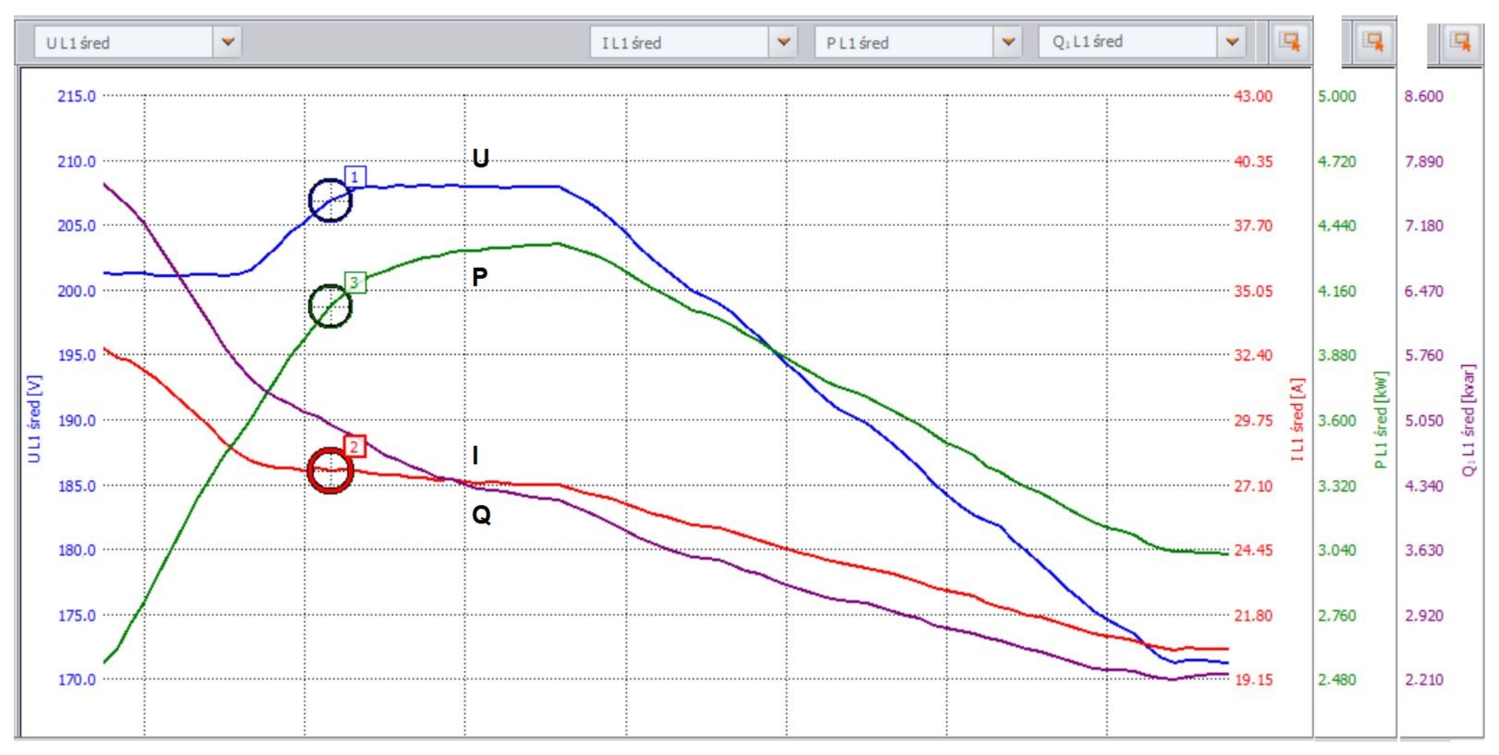
The use of regulators, i.e., the possibility of lowering the value of the luminous flux emitted, is used only assuming a change in the lighting class related to the night hours of operation of lighting installations.The new and already used luminaires with discharge sources can be used in road lighting, provided that they meet the requirements of EU regulations [
23]. They can have an adjustable value of the emitted luminous flux, which allows us to save electricity. For the analyzed case (
Figure 1 and
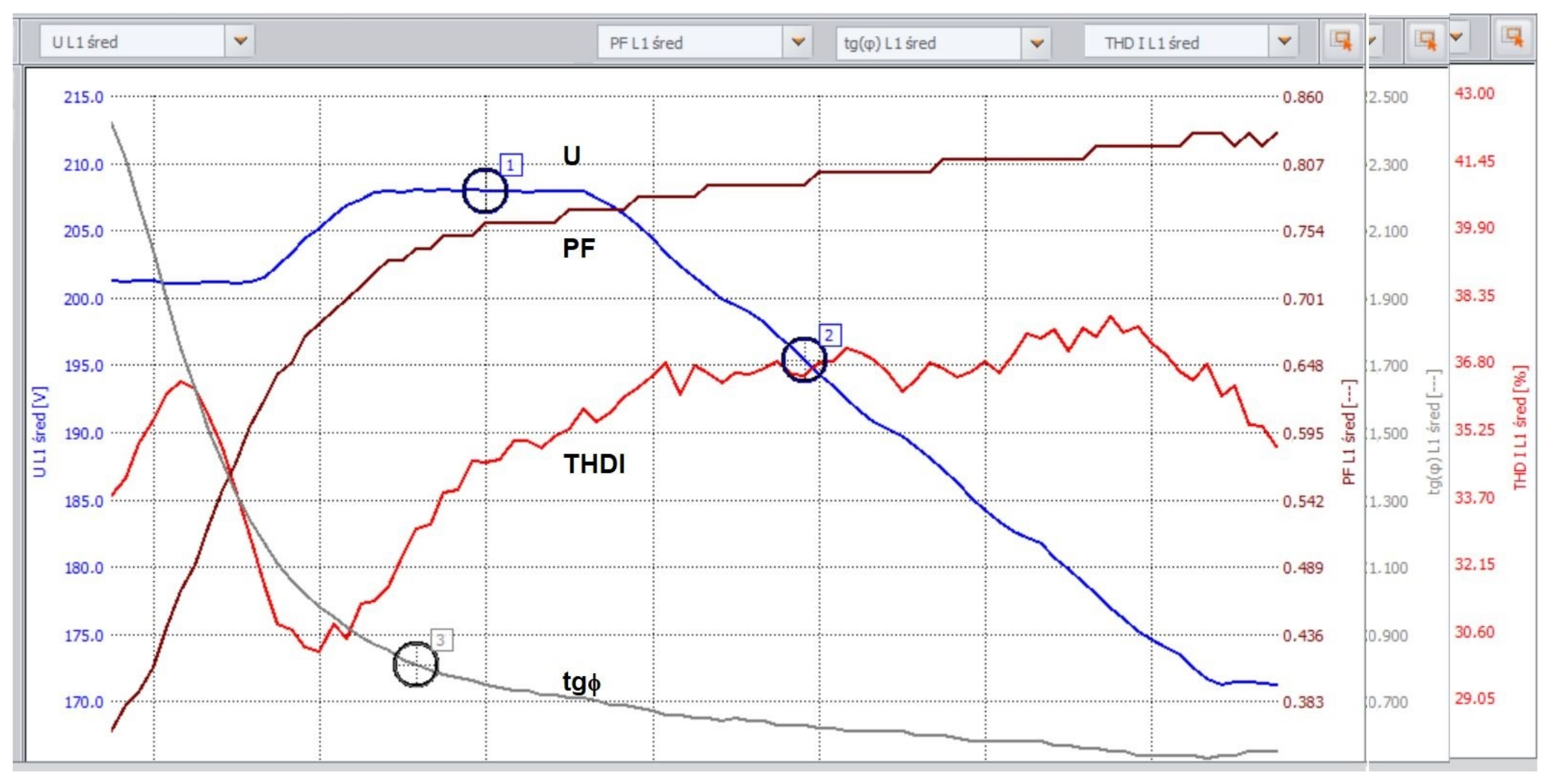
Figure 2), the savings amount to approx. 35% (the results include active energy consumption by the controller). On the basis of data from suppliers of voltage regulators, these savings reach up to 40% for large installations and with the use of several levels of voltage reduction. The presented results of the measurements of electrical parameters allow us to conclude that, when using voltage regulators, the value of supply currents decreases and the values of the PF and tg
coefficients improve. Unfortunately, the coefficients of the harmonic content do not decrease, which results in the need to use additional harmonic filters. The value of the tg
coefficient is greater than 0.4, which results in the need to replace capacitors in the luminaires (predictive maintenance) and/or use capacitor banks.
3. Road Installations with LED Sources
LED road luminaires are a breakthrough in the development of management systems. Their control is relatively simple. The smooth regulation of the luminous flux, an increase in luminous efficiency with a decrease in the supply current, no inertia between the control signal and the reaction of the device, and the universality and simplicity of the design of converters with the possibility of adjusting the luminous flux make using such a management system bring very measurable benefits in saving electricity, thus reducing costs and maintaining the comfort of use.
The system was extended with devices measuring the intensity of vehicle traffic; weather stations or light intensity sensors can save an additional 50% in relation to energy consumption for the installation controlled in the “0/100%” mode. In a simpler form (without the smooth adjustment of the luminous flux), when using a step control (e.g., a multi-stage power reduction), very significant savings in the amount of electricity consumed can be achieved: up to 35% in specifically implemented installations. LED matrix systems are powered by low DC voltage, most often 12 V or 24 V from power supply systems; these, in turn, are powered by a 230 V mains voltage and a frequency of 50 Hz.
Extensive electronic power supply systems perform control functions and supervise all important parameters related to the correct operation of the diode matrices, such as:
Stabilize the forward current;
Regulate the operating temperature of the diode arrays;
Control the amount of power consumed depending on the thermal conditions in the luminaire;
Reduce the value of the luminous flux in the event of improper thermal parameters of the luminaire’s operation;
Implement a programmed regulation of power consumed while reducing the level of lighting intensity (in accordance with the recommendations of the PN-EN 13201 standard, when the traffic intensity is low).
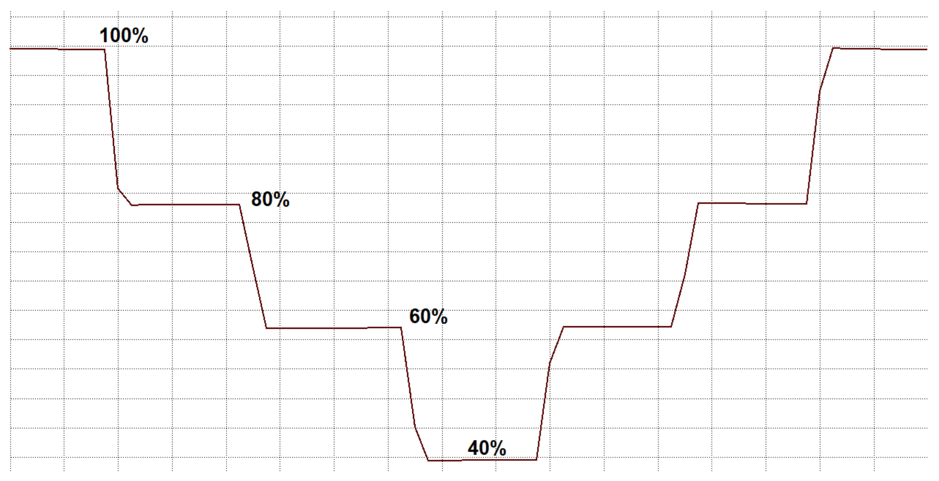
Regulators of LED road luminaires use one of two methods to adjust the value of the luminous flux: dimming, by reducing the active value of the current or voltage (phase regulation), or by adjusting the pulse width (PWM). Due to the wide control range and the linear relationship between the control level and the value of the luminous flux, the PWM method is more often used. The savings are associated with the use of luminous flux reduction “programs” at certain hours of the night (
Figure 3).
The diagram shows an example of a lighting “scene” that allows for a reduction in the flux to 100%, 80%, 60%, 40%, 60%, 80% and 100% of the rated value, respectively. Exemplary measurement results are presented in
Table 3 and
Figure 4 and
Figure 5. The analysis concerns the circuit of 10 LED luminaires powered by 230 V/50/Hz.
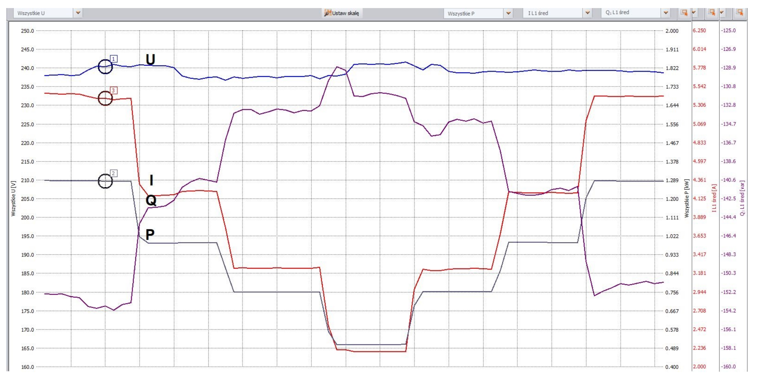
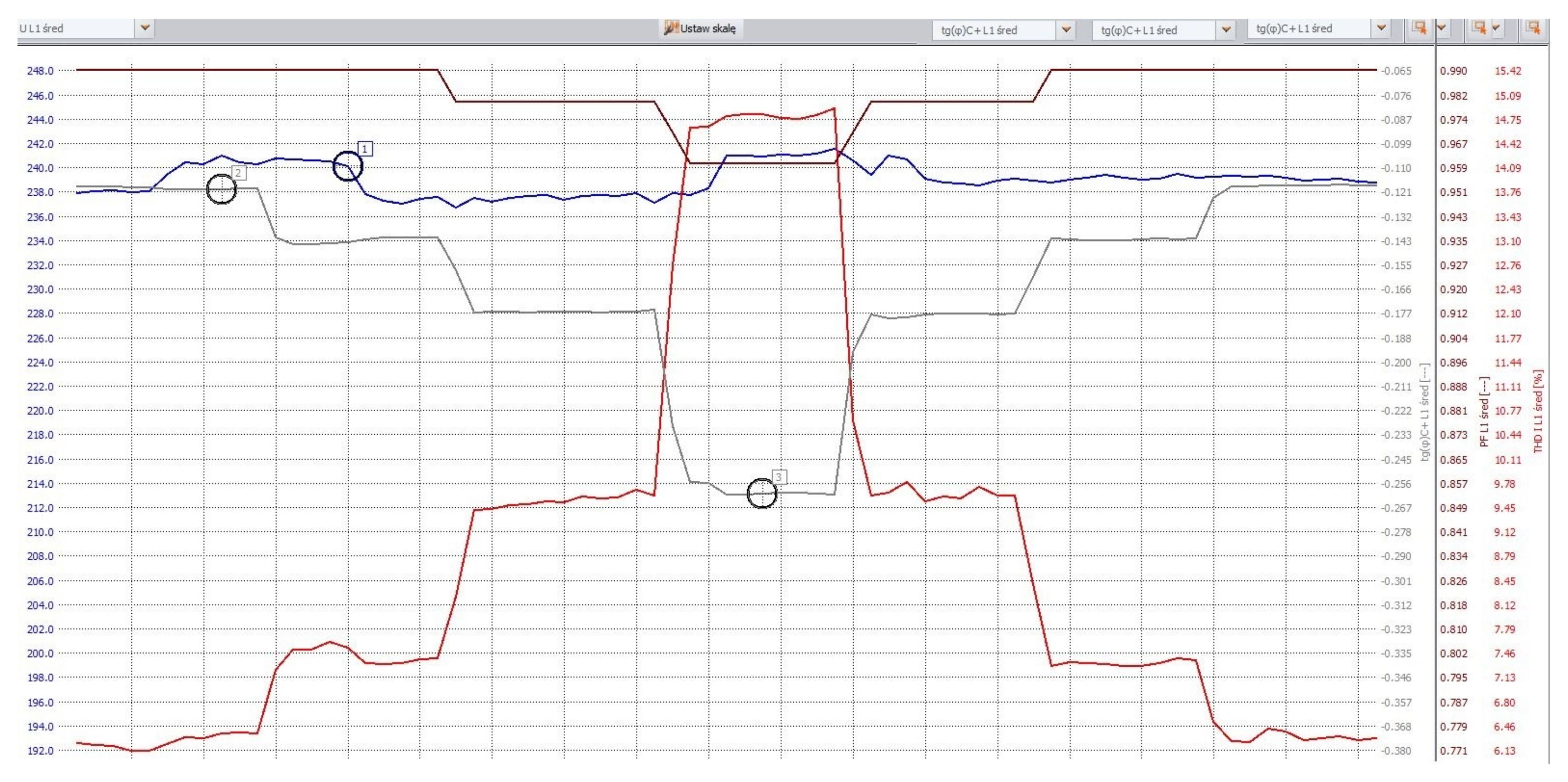
With the decrease in the luminous flux value of the luminaires, the THDI value increases in the range (2.85; 17.88%), the tg
value decreases in the range (−0.19; −9) and the PF power factor decreases in the range (0.98; 0.16) (
Figure 5). Lighting installations with luminaires equipped with LEDs are characterized by a negative tanning factor. Even with the rated data (100% of the emitted luminous flux), it has a negative value. Its negative value results from the selection of elements and systems in converters co-operating with light emitters. As the obtained results show, the reduction in the value of the emitted luminous flux obtained thanks to the control systems causes a significant increase in capacitive reactive power flows and thus an increase in operating costs. It clearly shows that the control does not change the electrical parameters of the lighting installation only up to a certain value (
Figure 4 and
Figure 5). Thus, the offers of companies that declare a reduction in the value of the emitted stream almost to “zero” do not take into account the fact that significant costs arise from the flow of capacitive reactive energy. In this type of installation, it is necessary to use reactive power compensation systems. This will mean high operating costs, which, as stated earlier, may be the reason for the lack of cost reduction, and sometimes even an increase in costs.
4. Analysis of an Exemplary Installation of Urban Lighting
The currently operating street lighting system was fully adapted to the comprehensive modernization of street lighting. The modernization was carried out in the form of a simple exchange of the luminaire for the luminaire. Such a replacement does not require interfering with the power supply system of the luminaires and is the fastest way to save money. The use of replacing the luminaire with the luminaire did not release the investor from the implementation of lighting projects based on the provisions of the 13201 series standards.
The lighting control system in the city is based on controlling the process of switching the lighting on and off by means of astronomical clocks. These clocks have sunset and sunrise times stored for each day of the year. This system guarantees the possibility of almost simultaneous switching on and off the lighting for independent circuits and enables the use of switching time corrections, planning and disciplining electricity costs. The introduction of the RSM system allows us to save approximately 40 min of lighting a day in relation to the astronomical clock. It is estimated that savings on the electricity used are approx. 10%. Thanks to the power reduction (CPA NET), electricity savings are estimated at approximately 15%.
The modernization of lighting in Bydgoszcz as part of the SOWA program allowed us to reduce electricity consumption in lighting subject to replacement by approx. 60%.
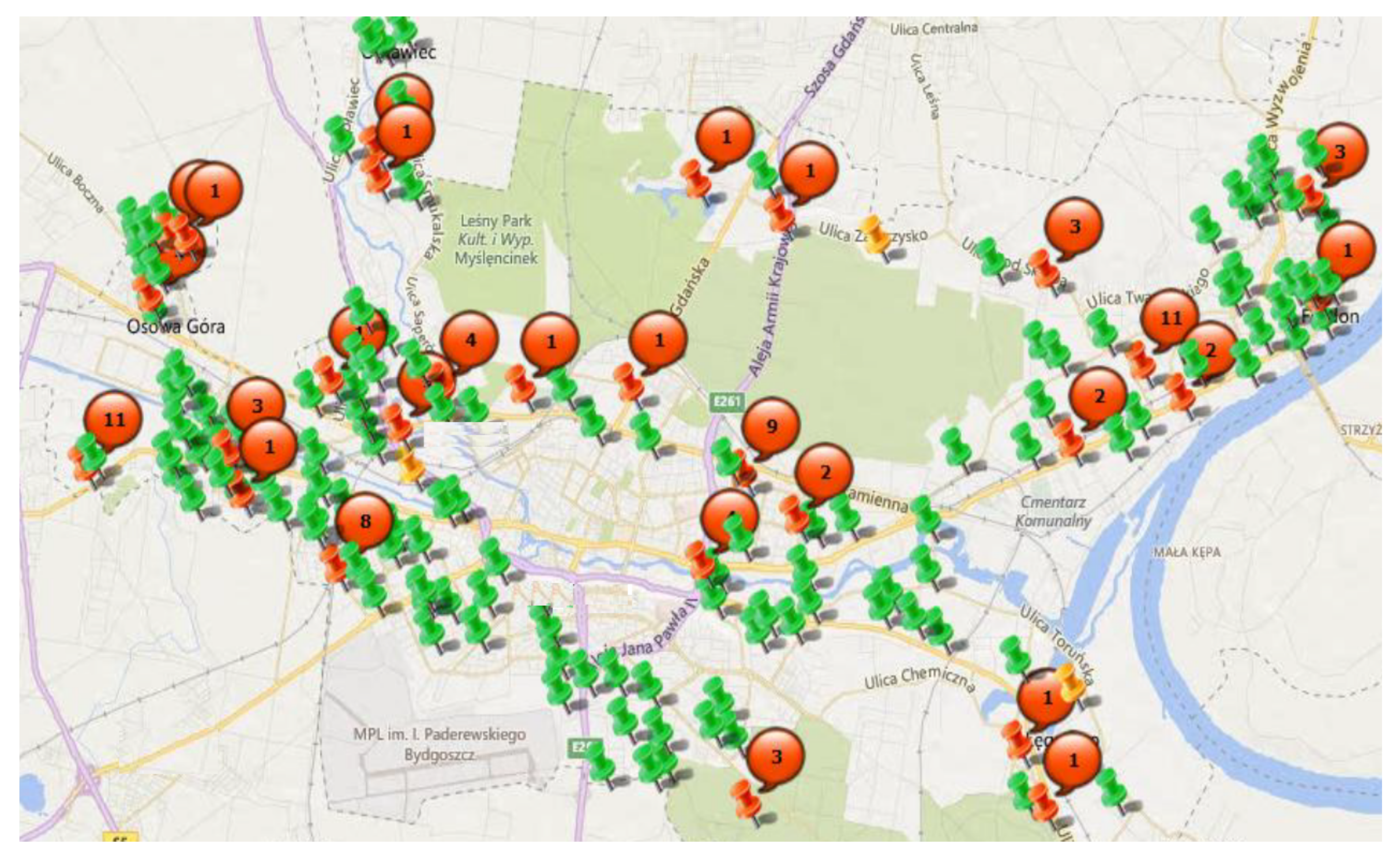
Figure 6 shows a fragment of the modernized installation which is the subject of the analysis in the article. The green "pins" in the drawing symbolize circuits with on-line access to measurement data. The numbers in the red circles are the number of alarm states (malfunctions in the operation of luminaires or measuring equipment) in the analyzed period of time. On the modernized lighting, a power reduction was applied, which allowed for an additional reduction in energy consumption on lamps undergoing modernization by an additional 10%. On the other hand, the above modernization allows us to reduce electricity consumption for all lighting located within the city limits by approx. 14%. The modernization allowed for: saving electricity, reducing carbon dioxide emissions, improving the quality of maintenance, accurately analyzing network parameters and precise budget planning based on a data read from the system. The disadvantages were: the high cost of modernization/construction and the need to use electric heaters that consume additional electricity (electronics used in lighting cabinets).
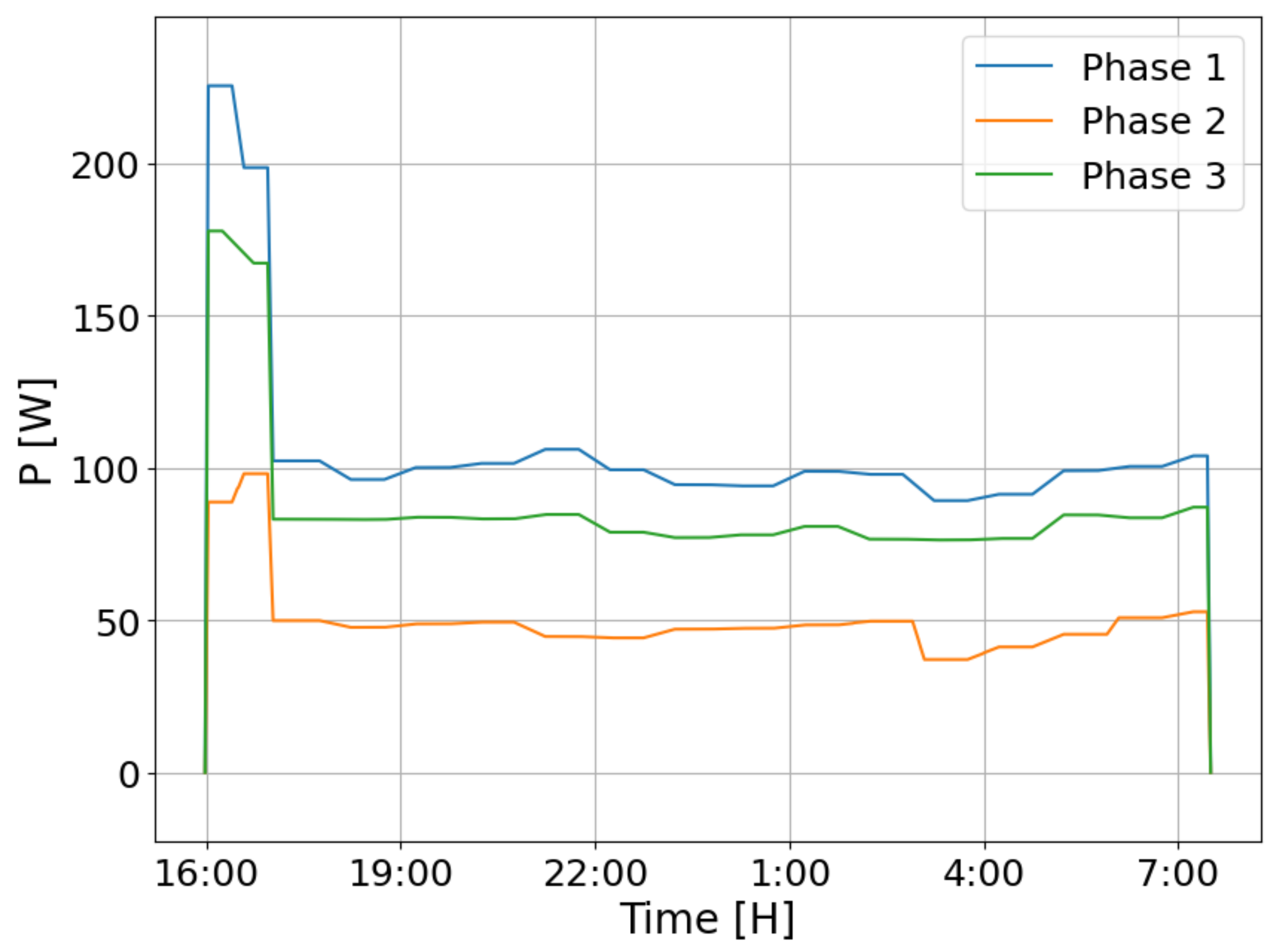
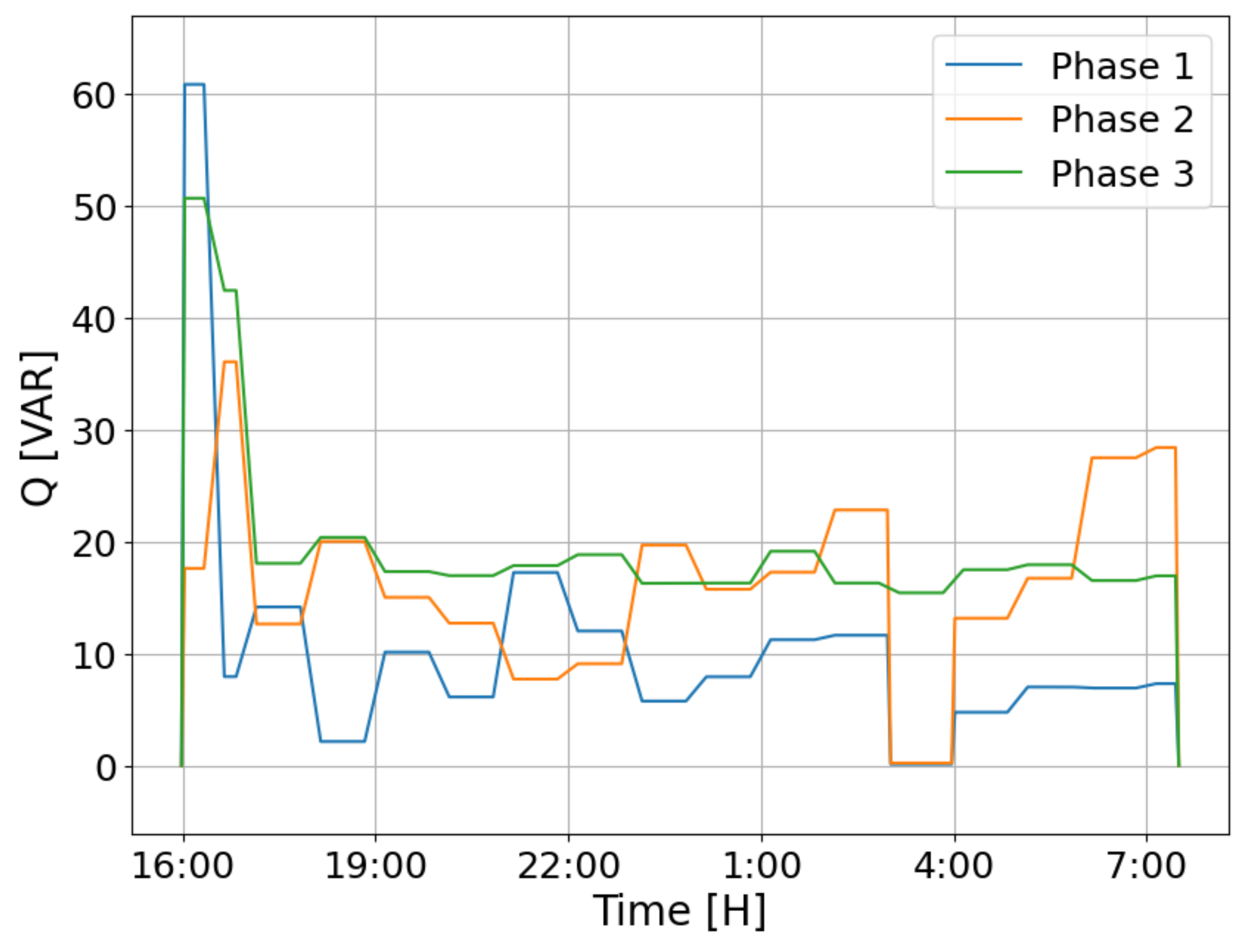
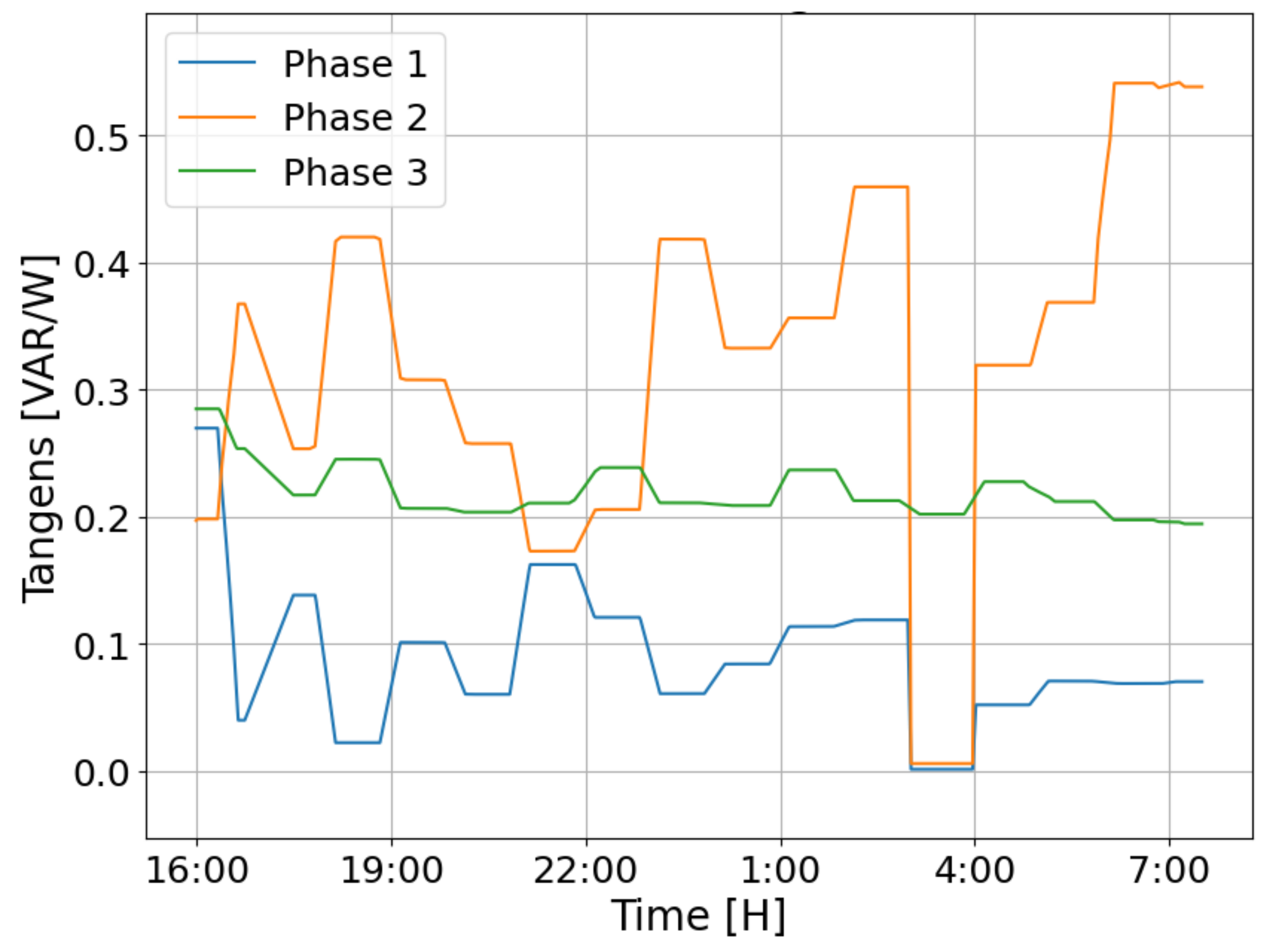
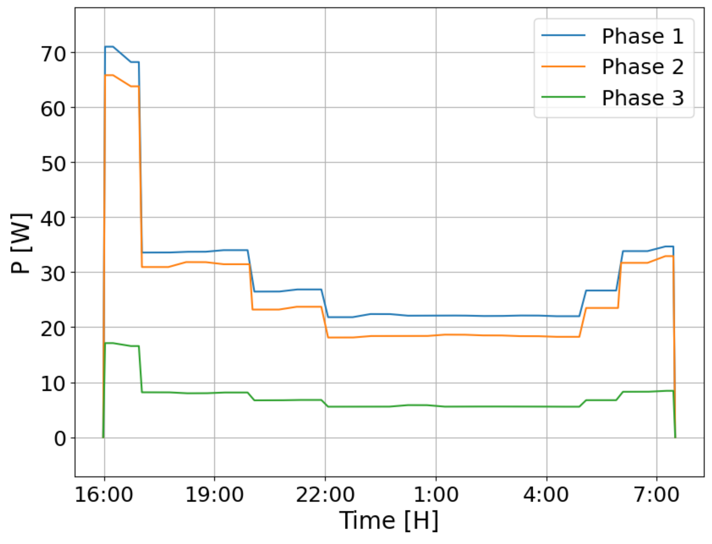
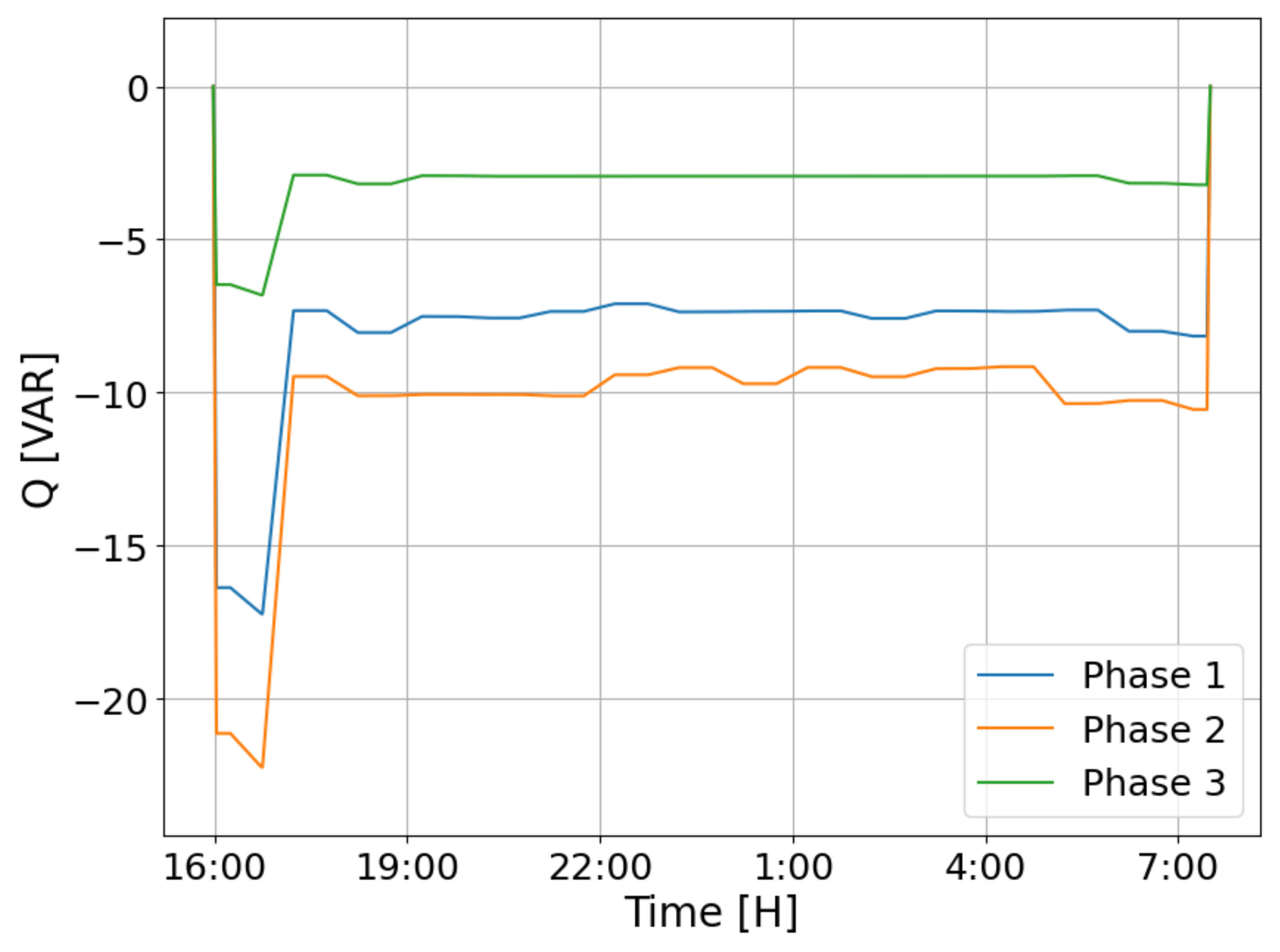
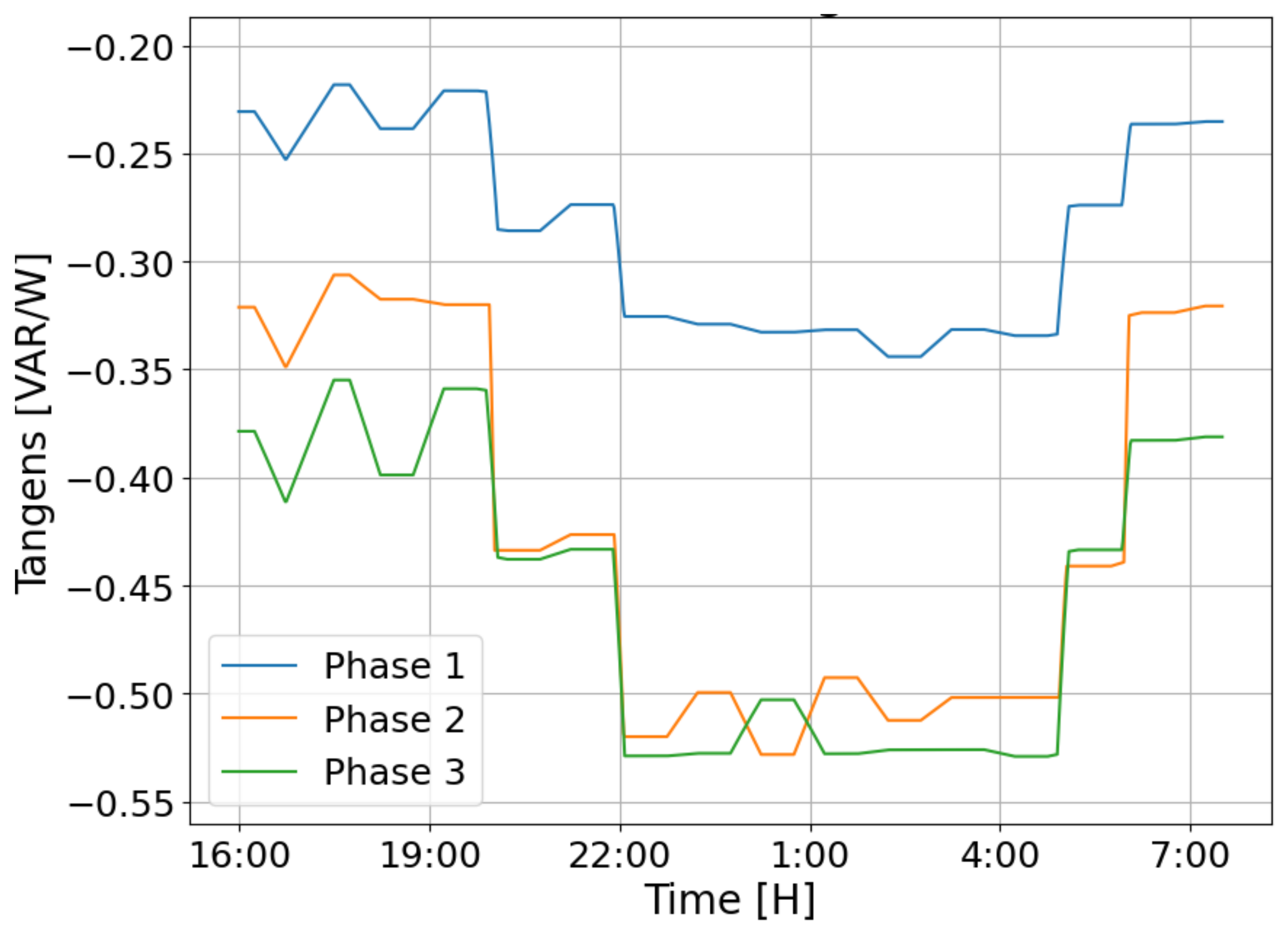
Unfortunately, the disadvantages also include a relatively high consumption of active energy and flows of reactive energy. The analysis was carried out in the cycle of one calendar year. The following figures present the course of changes in the values of active and reactive powers and tg
coefficients in the lighting installation with luminaires with discharge sources (
Figure 7,
Figure 8 and
Figure 9) and LEDs (
Figure 10,
Figure 11 and
Figure 12) (without reduction ) within 1 day.
In the operating lighting installation, the analysis of active energy consumption and passive energy flows was performed on two circuits with discharge sources and LED sources.
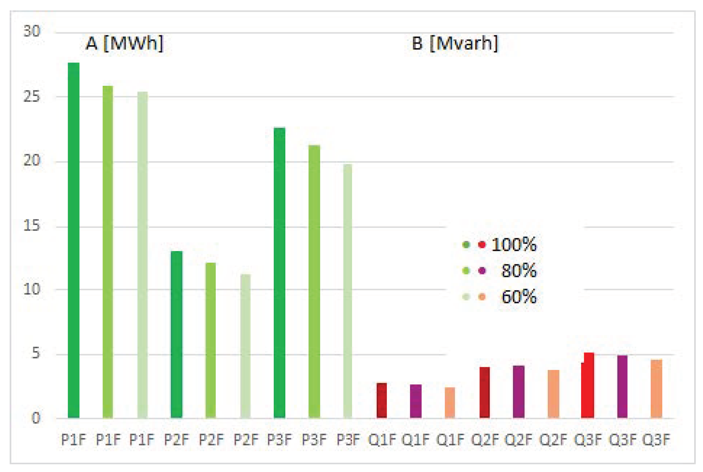
Figure 13 shows the consumption of active and passive energy in one circuit of the lighting installation of the luminaire with discharge sources (without reduction) during 1 year.
As can be seen from the presented comparison, the reactive energy values are very large (despite the use of individual compensation in the luminaires), and the circuits are asymmetrical.
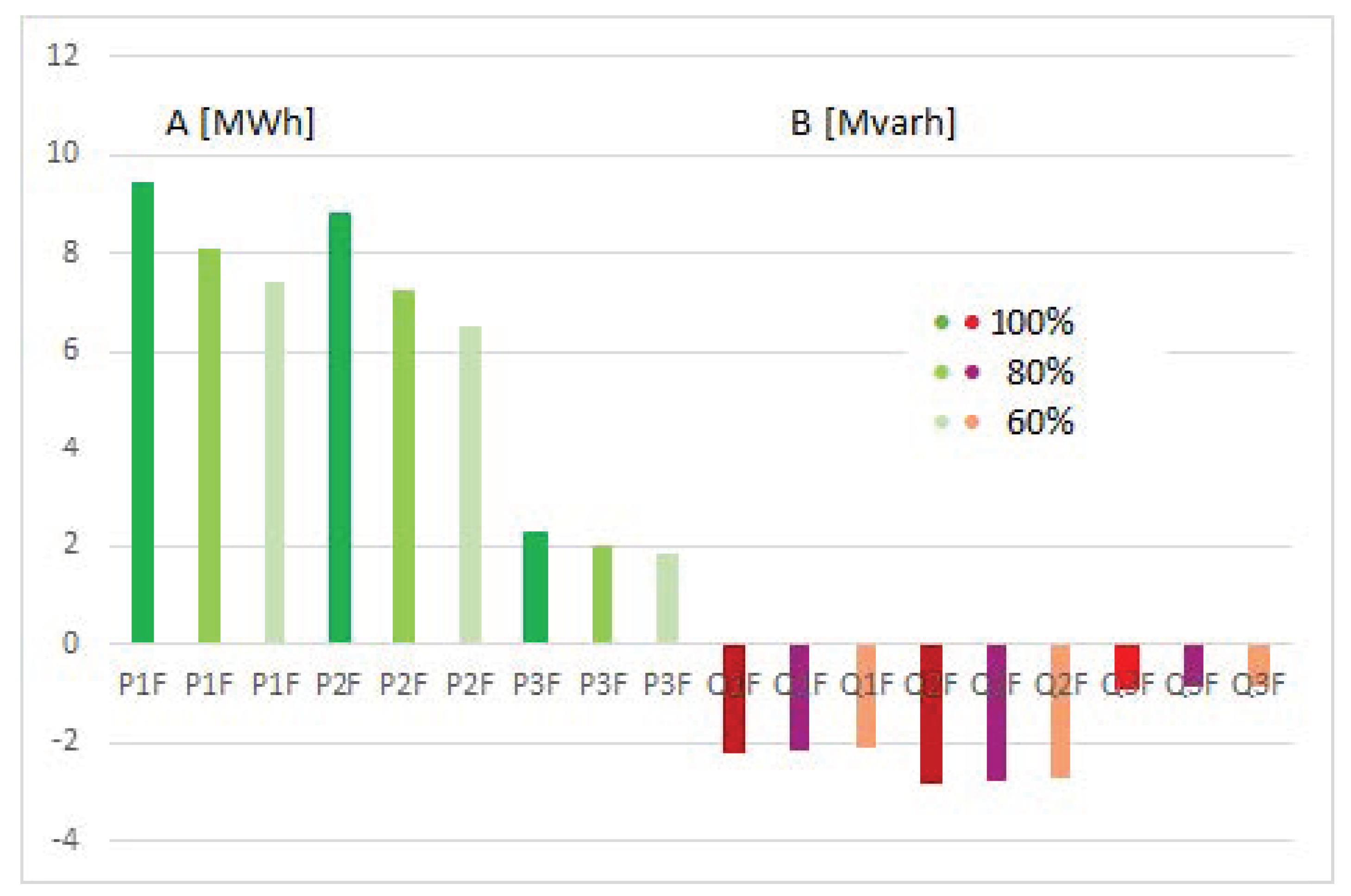
Figure 14 shows the active and passive energy consumption in one circuit of the lighting installation of the luminaire with LED sources (without reduction) during 1 year.
5. Conclusions
Based on the conducted energy audits and measurements of lighting installations described in the article, the authors put forward several general conclusions:
The control and monitoring devices can be used in already existing lighting installations. Unfortunately, in some of the installations used in lighting fittings with discharge and LED sources, converters that do not meet the harmonic content standards may be used. In addition, the total power factor PF is often neglected and only cos is indicated in the description or by the manufacturers. It is similar to the value of the rated power—only the power of the sources is given instead of the entire luminaire;
In some installations, an extensive measurement module should be provided for analyzing energy, reactive and active power, as well as PF and THD. The possibility in this regard ensures the optimal management of the supply network. Lower operating costs are, in turn, gained by monitoring the condition of the lamp, i.e., detecting and reporting failures. Modern lighting control systems focus on a flexible and distributed network structure. Its significant range and low operating costs are also important. The data exchange system often uses the 230V AC mains. The ability to remotely update the software plays an important role in this. Thanks to these devices, it will be possible to use more effective reactive power compensation systems (both individual and group). Control measurements in lighting circuits will make it possible to perform lighting audits based on actual electricity consumption data;
The use of lighting luminaire control systems (sets of luminaires) allows for high energy savings. The proposed solutions (sensors, devices and measurement systems) can also be successfully used in luminaires used outdoors (garden, street and road). These luminaires operate in a very wide temperature range, and also during the day. They are often covered with snow in winter. This changes the working conditions of light sources and electronic systems. The control of power parameters, and, above all, the monitoring of the operating temperature of the systems, enables a more effective operation of this group of lighting devices;
In the era of sodium lamps, two simple systems of “luminous flux control” were adopted: lowering the supply voltage to the minimum limit that maintains the discharge in the lamp, and the commonly known so-called power reduction. The voltage reduction is performed circumferentially so that the last lamp in the circuit is guaranteed to be lit. Power reduction is based on the use of ballasts that allow us to operate a lamp with one device at nominal power or, optionally, at a power reduced by one level in the power range. Such a reduction can be performed with or without the use of an additional control wire, depending on the needs. The adopted name of such a reduction—“50%”—does not reflect the realism of the situation at all. Due to the fact that the jump in the power range is less than 50%, and also due to the non-linear dependence of the luminous flux and the active power of the lamp, the savings are much smaller here. Taking into account that the reduced mode is approximately half of the total operating time, the additional savings from the methods used so far for sodium lamps are in the range of 10–20% compared to the energy consumption for an installation operated in “0/100%” mode. For the above-mentioned technical reasons, electronic ballasts with the possibility of regulating the luminous flux for sodium lamps have been used very rarely so far, which is largely justified, because neither energy savings nor comfort of use here are at the appropriate level;
LED road luminaires are a breakthrough in the development of management systems. Their control is very simple. The smooth regulation of the luminous flux, an increase in luminous efficiency with a decrease in the supply current, no inertia between the set signal and the reaction of the device, the universality and simplicity of the design of power supplies with the possibility of adjusting the luminous flux—all of this means that the idea of using such management brings measurable benefits in saving electricity and money, maintenance and the comfort of use. The system expanded with devices measuring the flow of vehicles, weather stations or light intensity sensors can save even 50% in relation to energy consumption for the installation operated in the “0/100%” mode. In a simpler form (without a smooth adjustment of the luminous flux), when using a step control (e.g., multi-stage power reduction), very significant savings in the amount of electricity used of up to 35% can be generated;
Lighting installations with luminaires equipped with LEDs are characterized by negative values of the tg coefficients. Their negative value results from the selection of elements and systems in converters co-operating with light emitters. As shown by the obtained results, the reduction in the value of the emitted luminous flux achieved by control systems causes a significant increase in capacitive reactive power flows, and thus an increase in operating costs. Offers of companies declaring a reduction in the value of the emitted stream to almost “zero” do not take into account the fact that significant costs arise from the flow of capacitive reactive energy. In this type of installation, it is necessary to use reactive power compensation systems.
Author Contributions
Conceptualization, M.K. and T.P.; methodology, M.K., T.P. and M.Z.; validation, investigation, M.K. and T.P.; analysis, M.K., T.P., M.Z., M.S. and B.K.; data curation, B.K. and M.S.; writing—original draft preparation, M.K., T.P., M.Z. and M.S.; writing—review and editing, M.K., T.P. and B.K.; theoretical modeling, M.K. and T.P.; software, B.K.; visualization, M.K., T.P., M.Z., B.K. and M.S.; supervision, T.P. and M.K.; project administration, T.P. All authors have read and agreed to the published version of the manuscript.
Funding
This research received no external funding.
Conflicts of Interest
Authors declare no conflict of interest.
References
- Dz.U. 2017 poz.1912, Regulation of the Minister of Energy of October 5, 2017 on the Detailed Scope and Method of Preparing an Energy Efficiency Audit and Methods of Calculating Energy Savings, Ministry of Energy, Poland. Available online: https://isap.sejm.gov.pl/isap.nsf/DocDetails.xsp?id=WDU20170001912 (accessed on 14 October 2017). (In Polish)
- Zajkowski, M. The SOWA program for the modernization of road lighting in the commune. Prz. Elektrotechniczn. 2015, R.91, 85–88. (In Polish) [Google Scholar]
- EN 61000-3-2 Electromagnetic Compatibility (EMC)—Part 3-2: Permissible Levels—Permissible Levels of Harmonic Current Emissions (Phase Current Supply of the Receiver < or = 16 A). Available online: https://webstore.iec.ch/publication/67329 (accessed on 13 November 2012).
- EN 61000-3-12 Electromagnetic Compatibility (EMC)—Part 3-12: Permissible Levels—Permissible Levels of Harmonic Currents Caused by the Operation of Receivers to be Connected to the Public Low-Voltage Power Supply Network with a Phase Current Supplying the Load Greater than 16 A and Less than or Equal to 75 A. Available online: https://webstore.iec.ch/publication/4144 (accessed on 13 November 2012).
- PKN-CEN/TR 13201-1: 2016-02—Road Lighting—Part 1: Guidelines for the Selection of Lighting Classes, Polish Committee for Standardization, Warsaw, Poland. 2016. Available online: https://sklep.pkn.pl/pkn-cen-tr-13201-1-2016-02e.html (accessed on 19 February 2016).
- PN-EN 13201-2: 2016-03—Road Lighting—Part 2: Operational Requirements, Polish Committee for Standardization, Warsaw, Poland. 2016. Available online: https://sklep.pkn.pl/pn-en-13201-2-2016-03e.html (accessed on 23 March 2016).
- PN-EN 13201-3: 2016-03—Road Lighting—Part 3: Calculation of Lighting Parameters, Polish Committee for Standardization, Warsaw, Poland. 2016. Available online: https://sklep.pkn.pl/pn-en-13201-3-2016-03e.html (accessed on 25 March 2016).
- PN-EN 13201-4: 2016-03—Road Lighting—Part 4: Methods for Measuring Lighting. Efficiency, Polish Committee for Standardization, Warsaw, Poland. 2016. Available online: https://sklep.pkn.pl/pn-en-13201-4-2016-03e.html (accessed on 23 March 2016).
- PN-EN 13201-5: 2016-03—Road Lighting—Part 5: Energy Efficiency Indicators. Polish Committee for Standardization, Warsaw, Poland. 2016. Available online: https://sklep.pkn.pl/pn-en-13201-5-2016-03e.html (accessed on 23 March 2016).
- Kurkowski, M.; Mirowski, J.; Popławski, T.; Pasko, M.; Białoń, T. Measurements of reactive energy in low voltage installations. Prz. Elektrotechniczn. 2016, R.92, 144–147. [Google Scholar]
- Lange, A.; Pasko, M. Reactive power compensation and filtration of higher harmonics using LC passive filters. Prz. Elektrotechniczn. 2010, R.86, 126–129. [Google Scholar]
- Djuretic, A.; Skerovic, V.; Arsic, N.; Kostic, M. Luminous flux to input power ratio, power factor and harmonics when dimming high-pressure sodium and LED luminaires used in road lighting. Light. Res. Technol. 2019, 51, 304–323. [Google Scholar] [CrossRef]
- Karim F., A.; Ramdhani, M.; Kurniawan, E. Low pass filter installation for reducing harmonic current emissions from LED lamps based on EMC standard. In Proceedings of the 2016 International Conference on Control, Electronics, Renewable Energy and Communications (ICCEREC), Bandung, Indonesia, 13–15 September 2016; pp. 132–135. [Google Scholar]
- Popławski, T.; Kurkowski, M.; Mirowski, J. Improving the Quality of Electricity in Installations with Mixed Lighting Fittings. Energies 2020, 13, 6017. [Google Scholar] [CrossRef]
- Sikora, R.; Markiewicz, P. Analysis of Electric Power Quantities of Road LED Luminaires under Sinusoidal and Non-Sinusoidal Conditions. Energies 2019, 12, 1109. [Google Scholar] [CrossRef] [Green Version]
- Ernst, S.; Kotulski, L.; Lerch, T.; Rad, M.; Sędziwy, A.; Wojnicki, I. Calculating reactive power compensation for large-scale street lighting. In Proceedings of the Computational Science—ICCS 2020, Lecture Notes in Computer Science, Amsterdam, The Netherlands, 3–5 June 2020; Springer International Publishing: Cham, Switzerland, 2020; pp. 538–550. [Google Scholar]
- Lerch, T.; Rad, M.; Wojnicki, I. Impact of Dimming LED Street Luminaires on Power Quality. Intl. J. Electron. Telecommun. 2021, 67, 255–260. [Google Scholar]
- Sędziwy, A.; Basiura, A. Energy reduction in roadway lighting achieved with novel design approach and LEDs. LEUKOS 2018, 14, 45–51. [Google Scholar] [CrossRef]
- Wojnicki, I.; Ernst, S.; Kotulski, L. Economic impact of intelligent dynamic control in urban outdoor lighting. Energies 2016, 9, 314. [Google Scholar] [CrossRef] [Green Version]
- Tomczuk, P. Assessment of the state of pedestrian crossing lighting on the basis of field measurements of luminance. Prz. Elektrotechniczn. 2013, R89, 266–269. [Google Scholar]
- Wiśniewski, A. Controlling external lighting—Electronic ballasts for discharge lamps. Prz. Elektrotechniczn. 2016, R.92, 182–185. [Google Scholar]
- Czapp, S. Current distortion in lighting systems and its impact on power supply installations. Acta Energetica 2009, 1, 25–39. [Google Scholar]
- Commission Regulation (EU) 2019/2020 of 1 October 2019 Establishing Ecodesign Requirements for Light Sources and Separate Control Gears Pursuant to Directive 2009/125/EC of the European Parliament and of the Council and Repealing Commission Regulations (EC) No 244/2009, (EC) No 245/2009 and (EU) No 1194/2012. Available online: https://eur-lex.europa.eu/legal-content/EN/TXT/PDF/?uri=CELEX:32019R2020&rid=6 (accessed on 5 December 2019).
Figure 1.
Characteristic of changes in the value of voltage, current, active power and reactive power in circuit 1 of the tested lighting installation—discharge sources.
Figure 1.
Characteristic of changes in the value of voltage, current, active power and reactive power in circuit 1 of the tested lighting installation—discharge sources.
Figure 2.
Characteristic of changes in voltage, total power factor, THDI and tg circuit 1 of the tested lighting installation—discharge sources.
Figure 2.
Characteristic of changes in voltage, total power factor, THDI and tg circuit 1 of the tested lighting installation—discharge sources.
Figure 3.
Diagram of reducing the luminous flux at night.
Figure 3.
Diagram of reducing the luminous flux at night.
Figure 4.
Characteristic changes in the value of voltage, current, active power and reactive power in circuit 1 of the tested lighting installation—LED source.
Figure 4.
Characteristic changes in the value of voltage, current, active power and reactive power in circuit 1 of the tested lighting installation—LED source.
Figure 5.
Characteristic changes in voltage, total power factor, THDI, and tg in circuit 1 of the tested lighting installation—LED sources.
Figure 5.
Characteristic changes in voltage, total power factor, THDI, and tg in circuit 1 of the tested lighting installation—LED sources.
Figure 6.
Arrangement of the tested circuits of lighting fittings.
Figure 6.
Arrangement of the tested circuits of lighting fittings.
Figure 7.
Characteristic of changes in active power values—luminaires with discharge sources (without reduction). Source: own study.
Figure 7.
Characteristic of changes in active power values—luminaires with discharge sources (without reduction). Source: own study.
Figure 8.
Characteristic of changes in reactive power values—luminaires with discharge sources (without reduction). Source: own study.
Figure 8.
Characteristic of changes in reactive power values—luminaires with discharge sources (without reduction). Source: own study.
Figure 9.
Characteristic of changes in the values of tg coefficients—luminaires with discharge sources (without reduction). Source: own study.
Figure 9.
Characteristic of changes in the values of tg coefficients—luminaires with discharge sources (without reduction). Source: own study.
Figure 10.
Characteristic of changes in active power values—luminaires with LED sources (without reduction). Source: own study.
Figure 10.
Characteristic of changes in active power values—luminaires with LED sources (without reduction). Source: own study.
Figure 11.
Characteristic of changes in reactive power values—luminaires with LED sources (without reduction). Source: own study.
Figure 11.
Characteristic of changes in reactive power values—luminaires with LED sources (without reduction). Source: own study.
Figure 12.
Characteristic of changes in the values of tan coefficients—luminaires with LED sources (without reduction). Source: own study.
Figure 12.
Characteristic of changes in the values of tan coefficients—luminaires with LED sources (without reduction). Source: own study.
Figure 13.
Active and passive energy consumption in 1 circuit of the lighting installation of the luminaire with discharge sources (no reduction—100%, with a reduction—80%, with a reduction—60%). Source: own study.
Figure 13.
Active and passive energy consumption in 1 circuit of the lighting installation of the luminaire with discharge sources (no reduction—100%, with a reduction—80%, with a reduction—60%). Source: own study.
Figure 14.
Active and passive energy consumption in 1 circuit of the lighting installation of the luminaire with LED sources (no reduction—100%, with a reduction—80%, with a reduction—60%). Source: own study.
Figure 14.
Active and passive energy consumption in 1 circuit of the lighting installation of the luminaire with LED sources (no reduction—100%, with a reduction—80%, with a reduction—60%). Source: own study.
Table 1.
Selected results of measurements of electrical parameters of a 3-phase lighting installation.
Table 1.
Selected results of measurements of electrical parameters of a 3-phase lighting installation.
| | U [V] | I [A] | P [kW] | Q1 [kvar] | SN [kvar] | S [kVA] |
|---|
| L1-N | 233.75 | 31.84 | 5.671 | 4.278 | 2.178 | 7.443 |
| | f [Hz] | PF [-] | cosj [-] | tgj [-] | THDU [%] | THDI [%] |
| L1-N | 49.98 | 0.76 | 0.80 | 0.75 | 3.47 | 30.40 |
Table 2.
Exemplary measurement results of electrical parameters (phase 1 circuit) for two values of power supply voltages of the fittings: 208 V and 171 V.
Table 2.
Exemplary measurement results of electrical parameters (phase 1 circuit) for two values of power supply voltages of the fittings: 208 V and 171 V.
| | U [V] | I [A] | P [kW] | Q1 [kvar] | SN [kvar] | S [kVA] |
|---|
| L1-N | 207.99 | 27.46 | 4.210 | 3.405 | 1.808 | 7.711 |
| L1-N | 171.12 | 20.39 | 2.872 | 1.619 | 1.148 | 3.490 |
| | f [Hz] | PF [-] | cosj [-] | tgj [-] | THDU [%] | THDI [%] |
| L1-N | 49.97 | 0.74 | 0.78 | 0.82 | 4.54 | 33.03 |
| L1-N | 50.01 | 0.82 | 0.87 | 0.56 | 4.41 | 34.46 |
Table 3.
Selected results of measurements of electrical parameters of a single-phase lighting installation.
Table 3.
Selected results of measurements of electrical parameters of a single-phase lighting installation.
| | U [V] | I [A] | P [kW] | Q1 [kvar] | SN [kvar] | S [kVA] |
|---|
| L1-N 100% | 237.97 | 5.447 | 1.284 | −0.153 | 0.083 | 1.296 |
| L1-N 80% | 237.82 | 4.211 | 0.988 | −0.141 | 0.076 | 1.001 |
| L1-N 60% | 237.66 | 3.241 | 0.755 | −0.134 | 0.075 | 0.770 |
| L1-N 40% | 238.23 | 2.209 | 0.504 | −0.129 | 0.079 | 0.526 |
| | f [Hz] | PF [-] | cosj [-] | tgj [-] | THDU [%] | THDI [%] |
| L1-N 100% | 49.99 | 0.99 | 0.99 | −0.12 | 1.36 | 6.12 |
| L1-N 80% | 50.00 | 0.99 | 0.99 | −0.14 | 1.42 | 7.32 |
| L1-N 60% | 50.00 | 0.98 | 0.98 | −0.18 | 1.42 | 9.49 |
| L1-N 40% | 50.02 | 0.97 | 0.97 | −0.26 | 1.43 | 14.64 |
| Publisher’s Note: MDPI stays neutral with regard to jurisdictional claims in published maps and institutional affiliations. |
© 2022 by the authors. Licensee MDPI, Basel, Switzerland. This article is an open access article distributed under the terms and conditions of the Creative Commons Attribution (CC BY) license (https://creativecommons.org/licenses/by/4.0/).


 ,
, 


