Article

Development and Validation of V2G Technology for Electric Vehicle Chargers Using Combo CCS Type 2 Connector Standards

1
MOBI-EPOWERS Research Group, ETEC Department, Vrije Universiteit Brussel (VUB), Pleinlaan 2, 1050 Brussel, Belgium
2
Flanders Make, Gaston Geenslaan 8, 3001 Heverlee, Belgium
3
Products Innovation & Systems Verification (PI&SV) Team, Powerdale (PWD), Witte Patersstraat 4, 1040 Brussel, Belgium
4
CR/AES3, Robert-Bosch-Campus 1, 71272 Renningen, Germany
*
Author to whom correspondence should be addressed.
Energies 2022, 15(19), 7364; https://doi.org/10.3390/en15197364
Submission received: 14 September 2022 / Revised: 3 October 2022 / Accepted: 4 October 2022 / Published: 7 October 2022

Abstract

:
Vehicle-to-Grid (V2G) technology is viewed as a viable solution to offer auxiliary power system services. Currently, V2G operation is only possible through DC chargers using the CHAdeMO connector with the necessary communication protocol. However, in Europe, for high-power DC charging (>50 kW), the Combined Charging Service (CCS) Type 2 is preferred over CHAdeMO. Therefore, this work presents the development of a V2G testing system with a Combo CCSType 2 charger including communication via the ISO 15118-2 protocol. The BOSCH passenger car with a 400 V battery pack is used to test and validate the technical feasibility of V2G charging via a Combo CCS Type 2 connector standard. The V2G feature is characterized in terms of efficiency, signal delay, response proportionality, magnitude accuracy and noise precision. A data driven V2G charger simulation model based on the real-time data is also developed in MATLAB/Simulink. The performance under various operating settings is presented in the outcomes, emphasizing the need for appropriate hardware calibration, and understanding while delivering standard-compliant grid control services using V2G technology. Finally, the results of the simulation model are compared with the real hardware results in terms of error, noise level and data magnitude accuracy.

1. Introduction

Electric vehicles (EVs) are becoming a popular means of transportation to ensure a clean environment. The majority of nations are making efforts to electrify their transportation systems, which are currently one of the main causes of the world’s carbon footprint [1]. For EVs, the electric charge of the battery is the main fuel to drive the car. To refuel the EV, we have to connect the EV to a charging station. For the EV charging pile, there are two options are available: (a) AC charging pile and (b) DC charging pile. They are differing from each other based on the charging voltage and current characteristics. In DC or direct current, the electrons flow in one direction steadily with zero frequency. In contrast, the electron changes its direction of mobility after a certain period periodically with 50 Hz frequency. The advantages of AC charging and DC charging are briefly discussed below [2]:
Benefits of DC charging over AC charging
  • DC chargers are bigger and faster than AC chargers.
  • All power conversion (AC/DC and/or DC/DC) occurs outside of the car. So, there are no power converters for DC charging inside the car. The charging current goes directly to the battery from the DC charger.
  • The electric vehicle that accepts DC charging can fast recharge while traveling a long distance.
  • Working with AC at high voltages is more dangerous than working with DC.
As the power converter is built within the DC charger itself, unlike AC chargers, electricity may be sent straight to the car’s battery without needing to be converted via the onboard charger. Because it needs a power source or transformer (a lot of electricity, such as 125A from the grid), the cost of charging is greater.
Benefits of AC charging over DC charging
  • Most parking spaces where a car will be parked for a longer period of time are ideal for AC charging.
  • The installation of an AC charging station is less expensive than DC.
  • An inductor or conductor can be used to lower the current without experiencing a significant energy loss because the current magnitude is not constant.
  • Rectifiers make it simple to convert AC electricity to DC.
  • A transformer may be used to produce a broad range of voltages.
  • When AC is delivered at higher voltages over larger city distances, the line losses are less in comparison to a DC transmission.
The main disadvantage of AC chargers is the speed of charging. Since the on-board charger is used for AC charging, the charging speed is depending on the design and technologies used during the on-board charger design. The majority of the EVs are left in parking lots for a sizable portion of the day, which means that the energy in their batteries is not being used. To transfer this underutilized EV battery power to the grid, Vehicle-to-Grid (V2G) technology was developed [3].
The V2G technology was first conceptualized by Kempton and Letendre in 1997 [4]. The power is usually transmitted from the generation unit to the customer (home, aggregator, etc.) in a conventional power system. An EV charging station functions as a consumer in normal operation, connecting the EV battery to the grid to charge it via the power connection. The EVs with V2G technology may return energy to the grid when the car is parked. Additionally, the V2G features enable more advantages such as peak shaving and labeling the demand, ancillary service to avoid the shortage. On the contrary, V2G has some barriers to using it commercially. The EV battery lifetime is reduced by frequently discharging for V2G service. Additionally, the public’s primary concerns with this strategy are the battery’s level of charge, local charging stations and infrastructure, as well as the initial high investment prices. Therefore, the rate of V2G system participation may be impacted, but this issue may be handled by putting in place a well-organized and motivating plan to assure the public of this system’s effectiveness [5]. The most significant barrier is to change the hardware modification inside the car. Moreover, establishing communication amongst the many stakeholders is the biggest obstacle to successfully using the V2G technology. To transfer the required instructions between the EVs, the electric vehicle supply equipment (EVSE), and third-party operators, V2G systems require communication protocols, both front-end and back-end [6]. The charging topologies (on-board/off-board), type of charging (conductive/inductive), safety, charging connections, communication, and cybersecurity criteria are all provided by the front-end protocols. They explain the relationship between EVs and EVSEs as well [7]. For instance, front-end protocols include communication standards such as IEC 61851, ISO 15118, SAE J2847, and CHAdeMO [8,9]. The back-end protocols describe criteria for communication and cybersecurity and provide links between EVSEs and third-party operators such as charge point operators (CPOs) [9,10]. A few examples of back-end protocols include the open charge point protocol (OCPP), IEC 63110, the open automated demand response (ADR), and EEBUS described in [11]. More information on these standards can be found in [12]. Due to the advancement in communication and devices, the V2G technology has attracted the researchers’ and OEMs’ attention to integrating EVs into the power grid with grid-supporting capabilities.
As a result of the increased attention being paid to V2G technology, approximately 50 V2G projects have been launched globally with the goal of identifying the best business models for all parties involved, including EV owners, chargers developers, utilities, and automotive OEMs [13]. Nissan is now collaborating with the German power company E.ON on the V2G services, distributed energy generation, and renewable energy systems business models [14]. Similarly, Volkswagen sees enormous potential in V2G [15,16,17]. The residential V2G charger from the Australian business EV-NRG has been released. It can control EV power depending on data from the vehicle and a series of sensors that track household loads and grid supply [11]. Additionally, V2G technology is developing via different projects around the globe. For instance, the ACES project tested V2G service in Bornholm, and Denmark tested V2G technology using the CHAdeMO standards to assess the feasibility of the provision of grid services [18]. The Parker project also demonstrated the V2G technology in 2016 with a CHAdeMO charging port to assess the grid support service to renewable power systems [19]. The real-time benefits of advanced vehicle-grid integration are assessed with the IEC 62196-2 standard on DC charging port in the INVENT project [20]. Moreover, this project enables UC San Diego to manage when and how electricity is drawn from EVs plugged into its charging stations to help power university buildings and facilities, saving both money and energy. The Grid Motion project has also investigated the V2G service feasibility in smart grid applications [21]. The summary of the state of the art of European V2G projects with associate charging standards is shown in Table 1.
The ChaoJi or GB/T connectors do not have a standard communication protocols whereas the CHAdeMO publishes the communication protocol for V2G in 2014 [23]. Currently, the V2G technology is only commercially possible through CHAdeMO DC chargers using the accompanying communication protocol, which also means that only cars using CHAdeMO, such as Nissan and Mitsubishi, can be used to test the V2G functionality. However, in Europe, most EVs use the Combined Charging Service (CCS) type 2 for DC charging together with the ISO 15118 communication protocol. There are three separate versions of the ISO 15118 standard: 15118-1, 15118-2, and 15118-3. The broad specifications and use case descriptions for V2G communication are provided in ISO 15118-1. It offers to charge confirmation, service certification, and start and stop charging instructions for electric vehicles. In order to satisfy the use cases established in 15118-1 for the network and application layer needs for V2G communication, ISO 15118-2 defines the message types and formats between the EV Communication Controller (EVCC) and Supply Equipment Communication Controller (SECC) [24,25,26]. However, the ISO 15118-2 protocol still needs some modifications to ensure V2G services. Moreover, for the real-time test of V2G technology with Combo CCS type 2, a simple communication unit needs to be added to the EV to regulate the power flow between the EVs and the grid. Designing this communication technology is expensive [9]. Therefore, most (European) EVs are not equipped with this unit, and they require a setup modification or adaptation to successfully establish a bidirectional power flow. Accordingly, the majority of the EVs on the European market today is not yet ready for V2G technology except for a few EVs manufactured by companies such as Nissan and Mitsubishi.
This paper attempts to enable V2G technology for Combo CCS Type 2 chargers by developing and validating a V2G testing system using the modified ISO 15118-2 communication protocol. This research also investigated the performance of DC chargers to the provision of V2G-based services. Additionally, a thorough modeling of the system in MATLAB/Simulink 2019b software environment, which takes the results of the tests into account, is developed to complete the research. The low-fidelity accurate charger model can be used as an effective tool for power system simulation studies for the grid integration impact assessment of the EVs. The investigated modeling technique of the real V2G system hardware can be able to contribute during demanding smart grid services such as frequency containment reserves (FCR). The remainder of the paper is structured as follows. Section 2 outlines the background information on EV charging connectors and communication standards. Section 3 outlines the V2G test system development and modification strategy. Section 4 presents a comprehensive discussion of the testing results including statistical analysis. Section 5 described the modeling of the V2G charger low-fidelity model in MATLAB/Simulink based on the real-time testing data. Finally, the conclusions are presented in Section 6.

2. EV Charging Connector and Communication Standard Background

International organizations have been working for many years to enact their connection standards regarding the high-power charging of EVs. The commonly used technologies are: (a) AC on-board charging and (b) DC off-board charging. In previous years, European EV manufacturers have rather produced EVs with on-board chargers which are compatible with a high-power AC supply. However, since the company TEPCO introduced a standard Japanese socket for DC connection, namely CHAdeMO, DC off-board charging is becoming more common. CHAdeMO is now available in several European countries, and although it is not internationally standardized yet, it is widely used in the US and Japan [27]. The SAE also has been developing its own connector standard called Combo. In SAE J1772, the Combo coupler features extra pins compared to the standard version [28].

2.1. AC Charging Connector

The IEC 62196-2 standard defines three types of connectors for AC supply power in Europe. These types of connectors are described in Table 2.
The IEC 62196-2 Type 1 is not different compared to the SAE J1772 which is widely used in the US and Japan. In China, the IEC 62196-2 Type 1 is also known as GB/T 20234.2-2015 connector. Notice that China has modified it by changing from an electronic lock into a mechanic lock (with the option of electronic lock) and the control pilot is using two short pins.

2.2. DC Charging Connector

The most common use of fast charging technologies is to supply the direct current to the EV battery. This requires an off-board charging station to supply high levels of current and to transform the AC of the distribution grid to DC for the charging of the EV’s battery. CHAdeMO was the first fast-charging method in the world, specified by the Japan Electric Vehicle Standard (JEVS) G105-1993 from the JARI (Japan Automobile Research Institute), and it has been developed by the Japanese company TEPCO. CHAdeMO is an abbreviation of “CHArge de MOve” or “move by charge” [30]. The connector includes two large pins for DC power, plus other pins to carry CAN-BUS connections. The CHAdeMO transmits the information by CAN-BUS and analog control lines. This hybrid communication protocol has more advantages compared to pure digital control, since it can let the system double-check the digital control system. Once the analog signal is lost, an immediate charging operation shutdown can be performed [28]. The CHAdeMO specifications comply with the international standard IEC 62196-3. The characteristics of CHAdeMO are shown in Table 3.
The configuration of CHAdeMO only specifies the necessary and effective parts for connection. A summary and pinout of CHAdeMO is shown in Table 4.

2.3. Combined Charger Connector (J1772-2009 Combo)

In parallel to CHAdeMO, the US and some European EV manufacturers such as Audi, BMW, Daimler, Ford, General Motors, Porsche, or Volkswagen have been developing a new system for fast charging: the Combined Charging System (CCS), i.e., J1772-2009 Combo. The main goal of this standard is to allow the EV to charge in both AC (slow/medium charging) and DC (fast charging), which is different from CHAdeMO as it only allows DC and needs an extra socket for AC charging.
There are two types of Combo CCS currently available. The Combo Type 1 connector for the US has been developed based on the AC Type 1 connector (specified by the standards SAE J1772/UNE EN 62196-2). The Combo Type 2 for Europe integrates a Type 2 connector as defined in the standard UNE EN 62196-2 [33]. The main characteristics of Combo connectors Type 1 and Type 2 are summarized in Table 5.
The Combo Type 1 and Type 2 have a different pinout configuration based on their different functionalities. Table 6 shows the configuration and the functions of the pins in the Combo Type 1 and Type 2.
Currently, GB/T was giving just 237.5 kW at 950 V and 250 A; thus, this will be about four times more competent in terms of power with other DC charging connectors. Power will be more than twice as high as the new 400 kW CHAdeMO and 350 kW CCS Combo specs, too. However, the V2G features is not supported by GB/T connector standard. The feature comparison among the DC charging connector standards is listed Table 7 below:

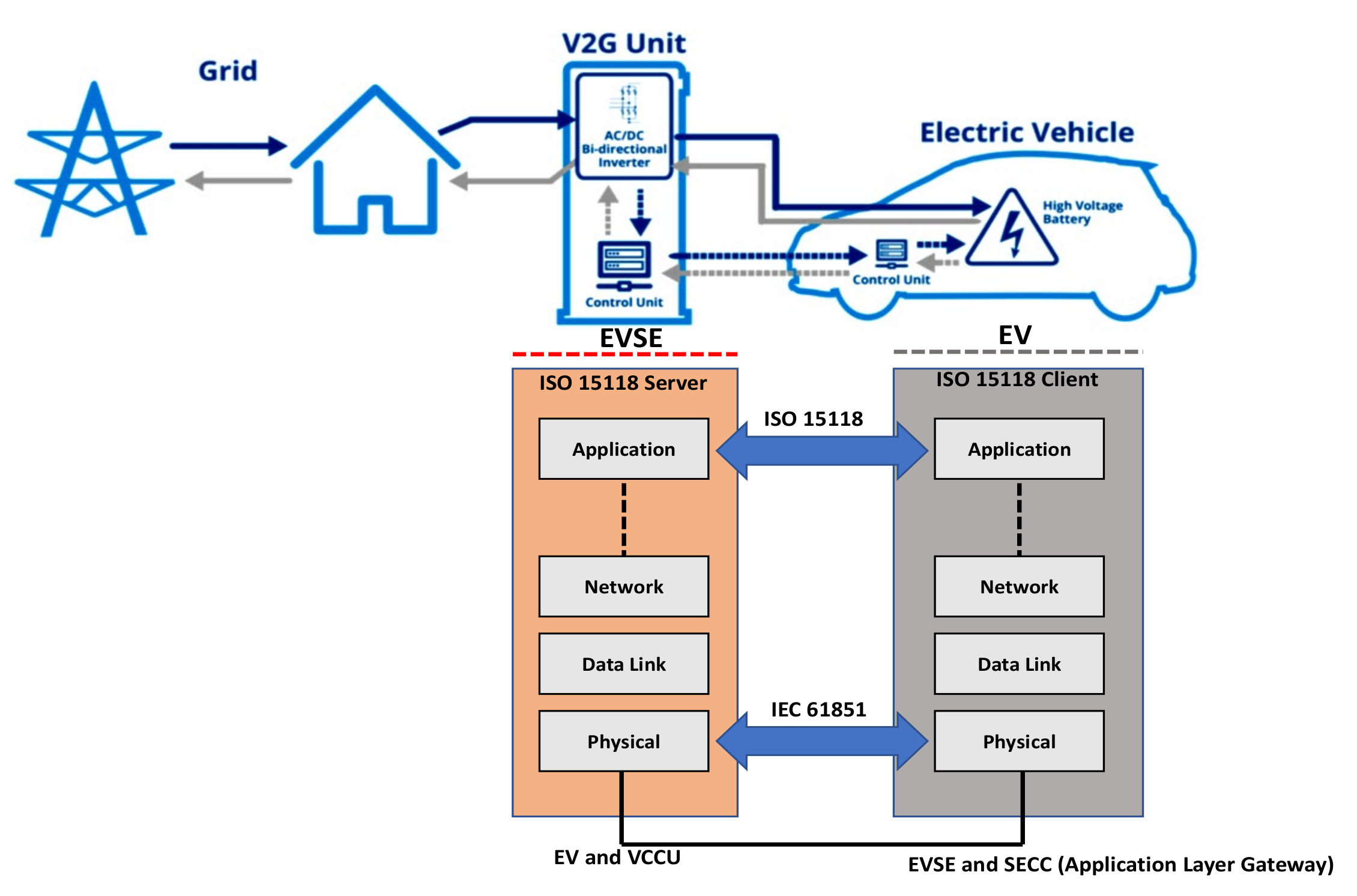
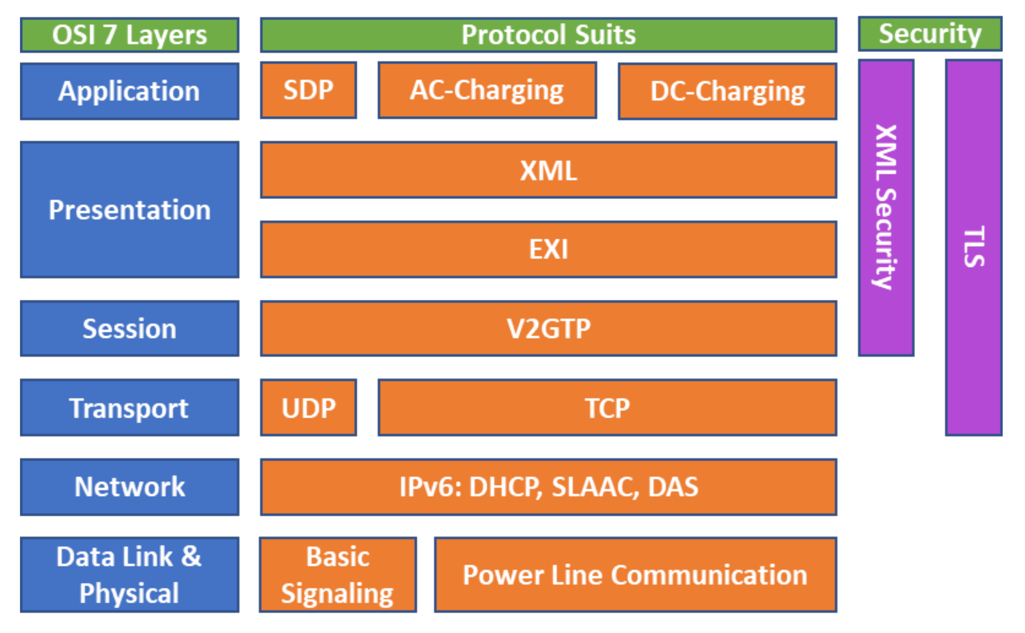
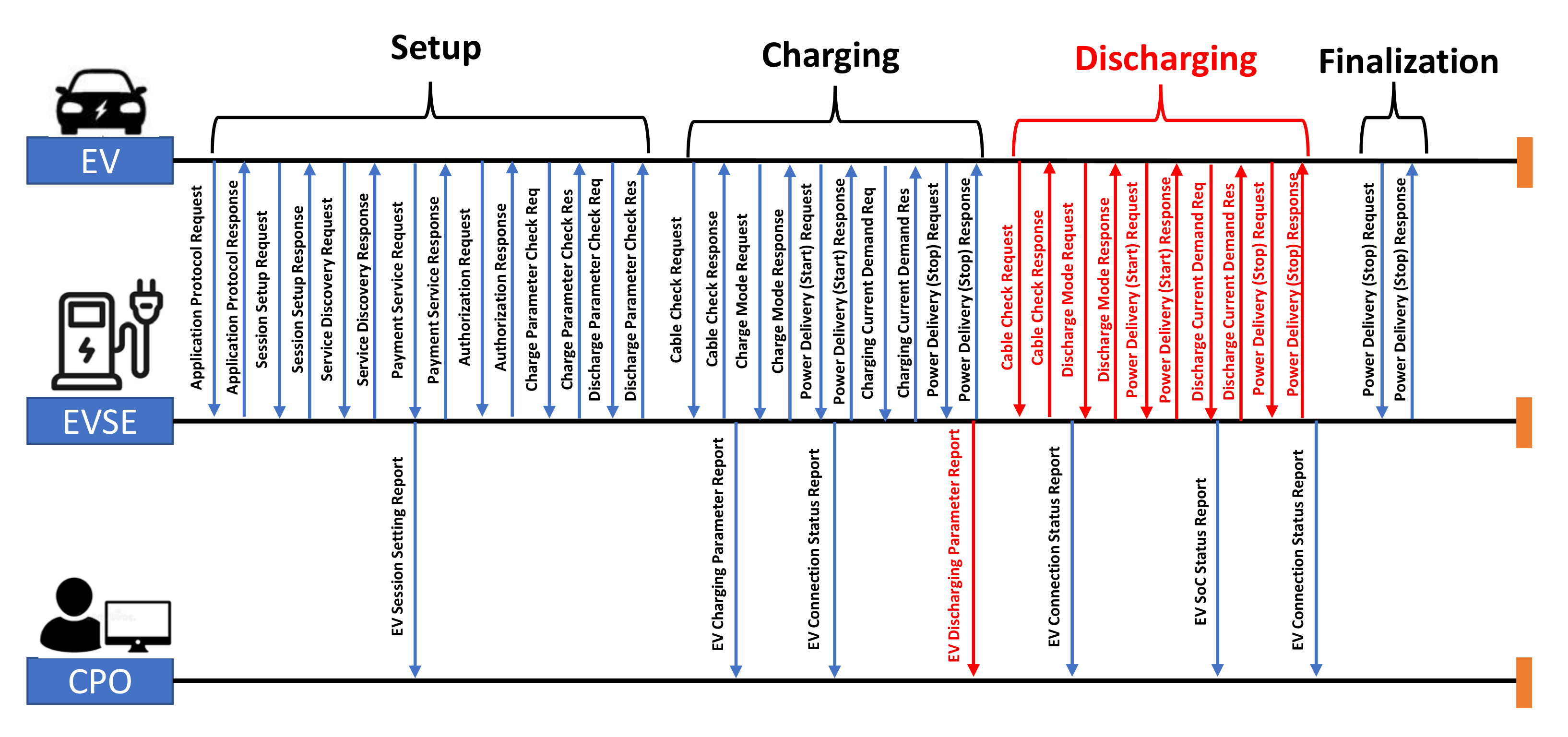
2.4. EV Charging and V2G Communication Standards

The design of an EV charging system and the relevant communication standards are shown in Figure 1. The EV and charging supply unit are the main key systems for EV charging. The EV is connected to the charging supply unit using a charging cable including communication wires. They usually use IEC 61851 for application-level communication standards and ISO/IEC 15118 for CAN communication standards. This high-level communication is specifically carried out by the EVCC in the EV and the SECC to regulate the whole charging process [34,35]. Third-party actors provide supporting responsibilities on the other side of the EVSE, such as billing and power management.
In this work, a high-level communication based on ISO 15118-2 is implemented, where the bidirectional feature is defined for the Combo CCS Type 2 connector. The IEC 61850 standard is also used for the operator and EVSE to exchange values relating to electricity. The messages produced by ISO/IEC 15118 and IEC 61850, however, are incompatible. The IEC 61850-90-8 was suggested to bridge communication between ISO/IEC 15118 and IEC 61850 in [36].

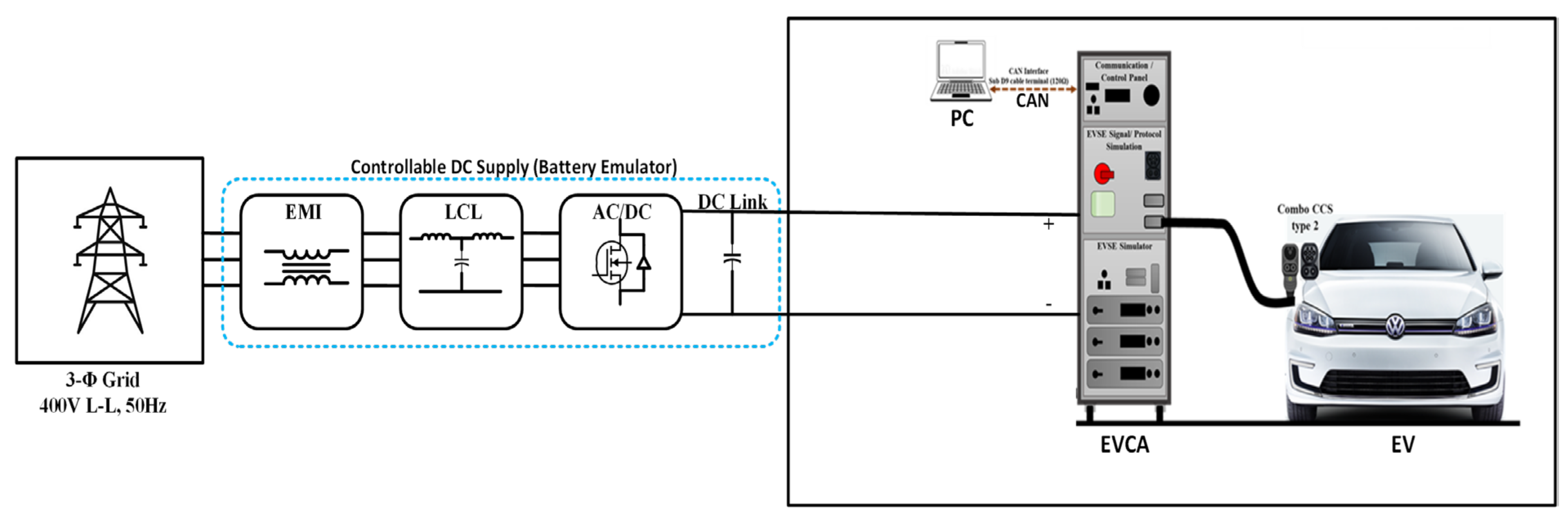
3. Test System Development

The DC charging test system architecture is shown in Figure 2. The novelty of this test system is the incorporation of the Combo CCS Type 2 charging port standard during V2G testing. Additionally, the BOSCH car is used as a baseline vehicle during V2G with necessary hardware and software modifications. The system modification details are described in Section 3.4 and Section 3.5. The test system consists of an Electric Vehicle Charging Analyzer (EVCA) and a battery emulator through which the system has been tested to ensure a safe operation in accordance with the current standards and charger interfaces. The required equipment to measure and verify communication, protection, safety, and load circuit—on the standard—conformity over the complete duration of charging and captures all deviations is used. In this way, it is possible to identify the non-conformity of charging and obtain the reasons for charge interruptions. The overall test system components are described in the next subsections.

3.1. Controllable DC Supply/Load (Battery Emulator)

DC programmable loads (80 kW): these devices can be used as battery simulators to get into the charge loop. The main features follow:
  • Per module: max. 1000 V with energy recovery.
  • Power up to 30 kW, and 150 kW by connecting two modules in parallel.
  • CAN interface.
  • Power monitoring module with redundant power contactors.

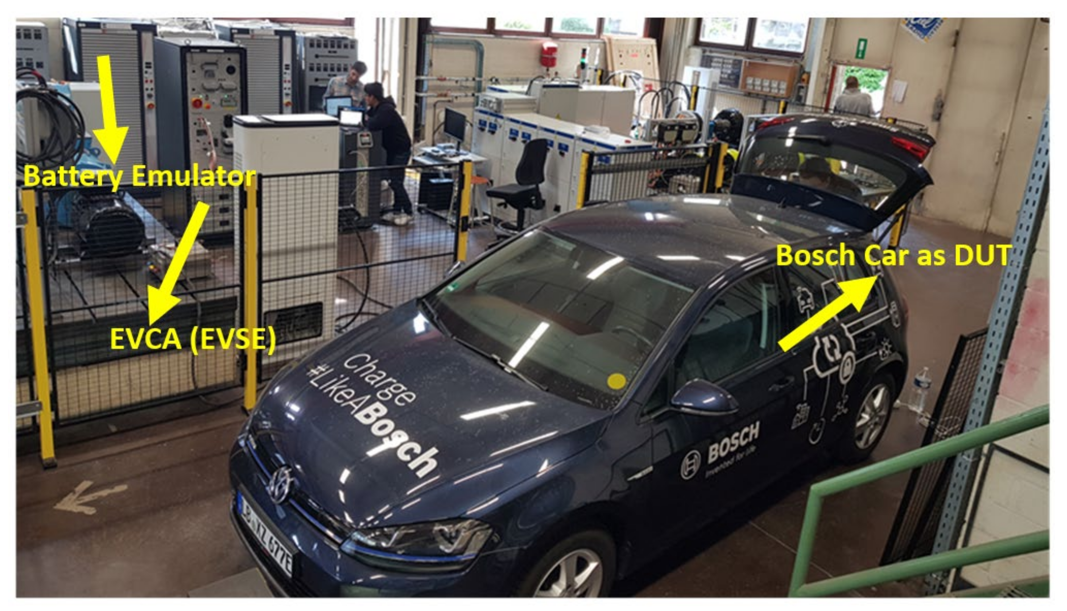
3.2. Electric Vehicle Charging Analyzer (EVCA)

An EVCA instrument measures and monitors both the load and the communication circuit for the entire charging procedure. By detecting and logging deviations from the standards, the conformity of all relevant parameters can be assessed when evaluating the measurement files. Results can be transferred by CAN to external data processing equipment. It can be used for testing all types of chargers (AC and DC chargers). The EVCA can operate in three modes: (1) EV emulator, (2) EVSE emulator (AC and DC), and (3) Man-in-the-middle. This unit is designed for testing the conductive charging of electric vehicles. The main features are:
  • Data recording and controlling on CAN interface as “Remote Control”.
  • Isolated banana sockets for control pilot of EVSE for comparison with an oscilloscope.
  • Integrated electronics for measuring Voltage up to 800 V and Current up to 200 A.
  • Integrated high-power resistors for isolation test with ca. 100 mA leakage current at 500 V DC.

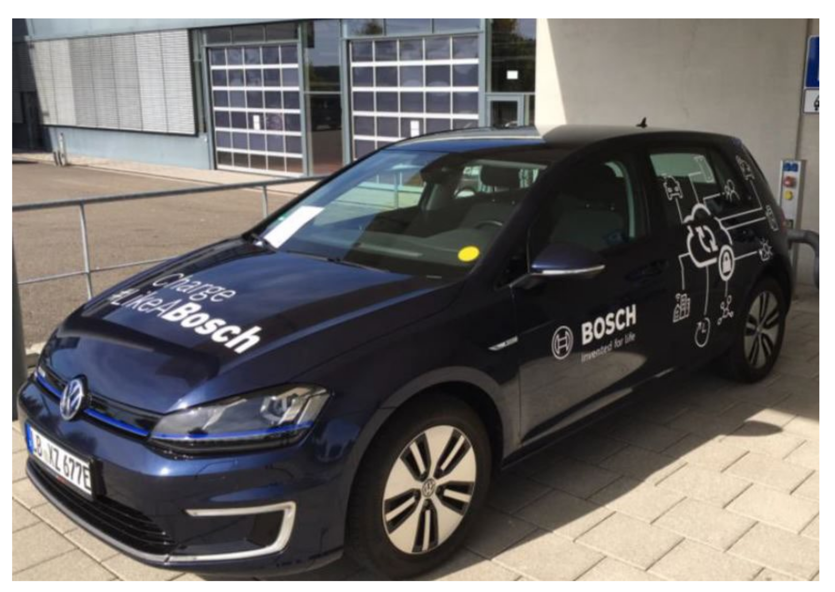
3.3. Electric Vehicle DUT (BOSCH)

ROBERT BOSCH GmbH supplied the passenger EV shown in Figure 3 to perform the charging test. The company technical team replaced the CHAdeMO port with a Combo CCS Type 2 connector to perform AC and DC charging tests compatible with the above-mentioned test infrastructure. Additionally, a vehicle control unit was installed to enable DC V2G with a Combo CCS Type 2 connector and the ISO 15118-2 communication protocol.

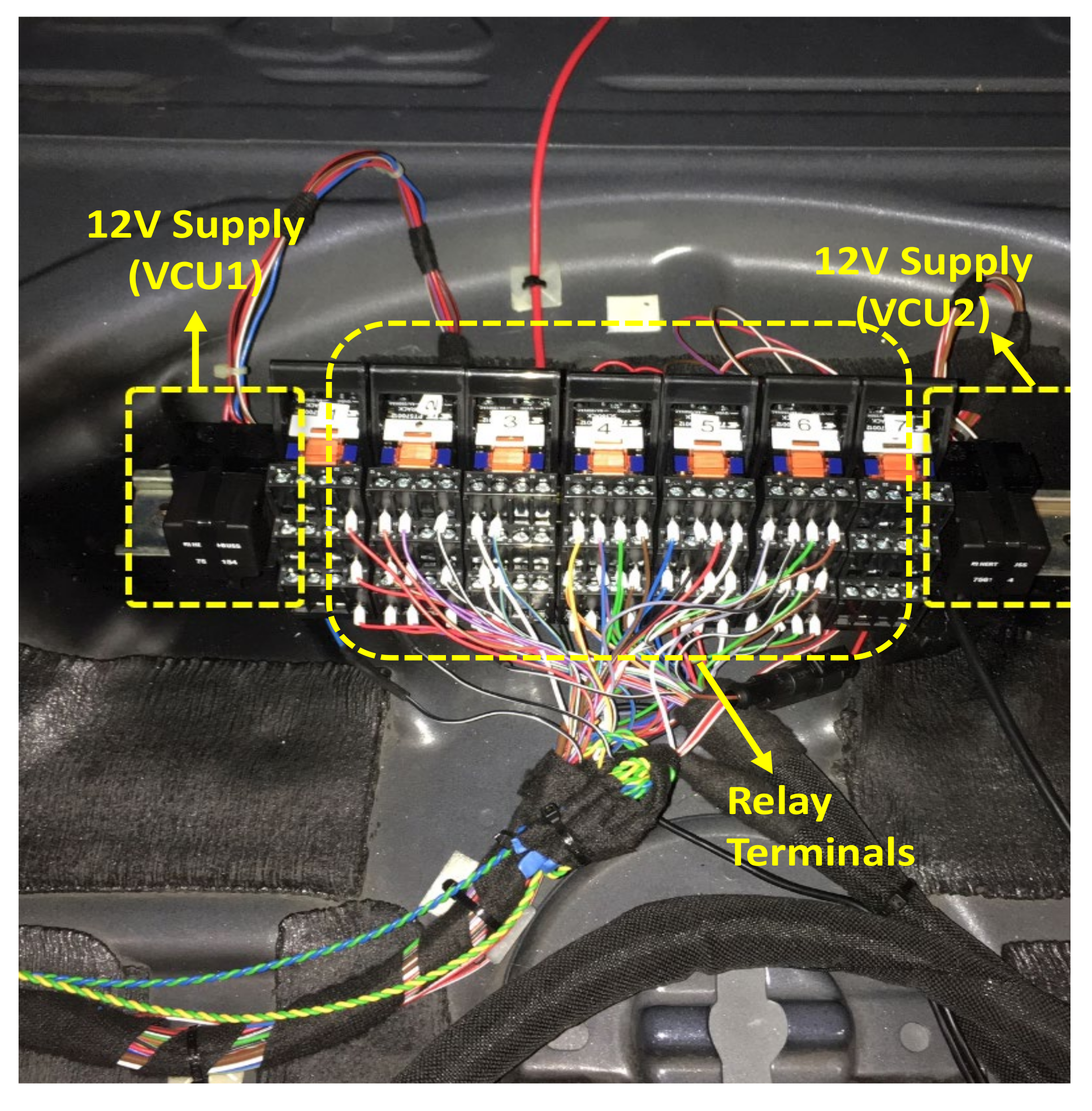
3.4. Additional EV Hardware Modification for V2G

The EV has been equipped with an additional vehicle control unit (VCU) as shown in Figure 4 to enhance the V2G setup. The VCU is usually used for vehicle state management, communication with the backend, coordination, etc. In this test setup, the additional VCU has also direct interfaces to connect debugging tools for developing/modifying the software and monitoring all vehicle internal bus messages as well as the ISO 15118-2 communication. The automotive-compliant changeover relay for switching the 12 V supply voltage between the series VCU and the additional VCU is shown in Figure 5. A dedicated relay terminal is also switched over with the same changeover relay. This means that only one VCU can be active at the same time.

3.5. Software Modification for V2G in EV

The bidirectional charging functionality has been implemented based on the ISO 15118-2 specification which is shown in Figure 6. The Power Line Communication (PLC) is employed at the physical and data-link layers. User Datagram Protocol/TCP (Transmission Control Protocol) is utilized for the transport layer on top of PLC, while IPv6 is used for the network layer. Although the testing system does not explicitly test these protocols since they are properly implemented by commercial operating systems such as Windows or Linux, it will indirectly discover the poor implementation of these levels.
The ISO/IEC 15118 standard defines the communication protocol during the V2G test, which is used for session management. All requests are sent via energy transfer protocol as a message group. The protocol just confirms the ISO/IEC 15118 version compatibility of the message request data packet. After the EV charging or discharging setup initialization is the request packet initiation; the EVCC broadcasts a request packet using this protocol, and an SECC responds by sending back a response. The response detects the charging controller’s IP address and communication port identification. The later packet type is the application (charging/discharging) message, although the actual message in the transmission is multiplexed by the EXI method to reduce packet density. Every application message is internally represented in XML for higher versatility and adaptability. For each type of application message, the user sends a request message, and the ISO 15118 server responds with a response message. This is known as the client-server model of communication ISO standard [36]. The EV and charging supply unit exchange the essential messages prior to the whole charging process through a sequence of request and response messages, as seen in Figure 7. For instance, the EVSE receives the SSR messages from the EV for the set initialization message type and responds with the acknowledgment message. However, the sequence of the application message types in the table approximately corresponds to the actual message sequence. The message exchange sequence is shown in Figure 8.
Thus, during the “charging loop/re-scheduling”, the ISO 15118-2 is extended to be able to handle negative current requests to enable the DC discharge functionality.

4. Testing Results and Discussions

The V2G test setup with EV and charging supply unit is shown in Figure 9. Tests are especially conducted to focus on V2G power transfer through the Combo CCS type 2 connector standard. The overall system is comprised of a battery emulator, EVCA, EVSE, and BOSCH passenger car with a Combo CCS2 connector and checking the ISO 15118-2 communication. The communications among the EV, the charging supply unit, and the operator were manually examined, and the timings of message deliveries were checked to ensure that the target EV charger is properly tested.
The battery voltage and current are shown in Figure 10. The operator specifies the discharge current setpoints. Initially, the discharging current is set to −10 A, and then, it is increased up to −30 A. The battery voltage starts from around 323 V to decrease during discharging. The current waveforms from the AC side, which feeds the grid, are depicted in Figure 11. It can be observed that the AC voltage is around 220 V and is in phase opposition with the grid current. The THD level of the discharging current in the AC side is lower than 5%. The discharging power to feed the grid is around 10 kW. However, the discharging current is a bit distorted and has some noise.
The overall V2G test is performed for approximately 593 sec. The operator controls the discharge current setpoint over the entire period. The DC current is following the current setpoint with a delay of 2 sec, which is shown in Figure 12. The DC voltage from the battery side is decreased over the discharging period. The discharging power is the product of DC voltage and current, as shown in Figure 13. During the test, the limit of the discharged power is between 4.8 and 9.6 kW. Moreover, the discharged power on the grid side is estimated by the grid side current. The grid voltage is 230 Vrms and the power factor is approximately 0.975 leading. The grid current profile at two different vehicle discharge power levels is shown in Figure 14 and Figure 15. Additionally, this current profile is recorded at 45% battery SoC level. So, the discharging efficiency is estimated at three different battery SoC levels, which are shown in Figure 16. The efficiency slightly varies with the initial SoC level. According to Figure 16, it is possible to obtain a higher discharging efficiency at a high initial battery SoC level.
The signal delay between the reference and the actual signal indicates the controller response delay. It just provides the hardware response as it occurs, without any further delays brought on by miscellaneous setup communications between the reference and the measurement. The signal delay is determined using the cross-correlation method. Figure 17 depicted the correlation the reference and actual signal which describes how two signals correlate when one of them is subjected to various temporal shifts during the test. The peak is detected for a signal delay of around 2 sec, which is then taken into account as the activation time of the tested V2G apparatus. The charger communication testing architecture is implemented with the full stack of ISO/IEC 15118, including IEC 61851 standard signaling. In this way, the DC charger can exchange energy between an EV connected by a Combo CCSType 2 connector and the grid via standard communication. However, while the reference controller exchanges from the 15118 server and 61851 mobile applications, the main message for energy exchange is transmitted from the ISO 15118 server through different communication layers such as the physical layer, data link layer, etc. The communication architecture of the charger includes the 15118 servers, the 61851 module and the reference controller, as shown in Figure 18.
The communication testing results for the specific DC charging cases and the reference design with different data transfer protocols are shown in Table 8. It is noted that the EV charger passed every request and response test, including the unfavorable ones. The test system was capable of concurrently acting in the capacities of the operator and the EV.
The reference controller interacts with the 15,118 servers and 61,851 modules to regulate the overall operation of the EVSE. The PLC converter, which changes the data to the control pilot and vice versa, receives communication from the 15,118 server and 61,851 modules to connect with the EV. The combo-type coupler is supported by the reference charger for connecting to the EV. Figure 19 displays the outcomes of messaging time to initiate and begin DC discharging with the improved EV.

5. Data-Driven V2G Charger Model Development

Investigation of the impact assessment of large-scale DC charging stations with V2G facility on the existing power system or microgrid is a popular research topic of recent years. This research reveals the positive and negative outcomes of the V2G facility in peak shaving, frequency regulation, the total cost of ownership reduction, and social barriers. Thus, a DC charging station simulation with a practical V2G charger model is very important. In this regard, a V2G charger modeling approach is described in [37]. A similar approach is followed to develop the real-time V2G charger model based on the tested data. This model is a low-fidelity model with less required simulation time requirement. Therefore, this model can be used for detailed simulation studies when investigating the impacts of DC-EV chargers with V2G features on the grid. The EV charger model is designed using the Simulink platform within the MathWorks 2019b software environment. The schematic representation is shown in Figure 20.
The input of the model is the reference signal which is sent to the real-time controller from the user side. Using this reference input, the model processes this reference signal data based on the signal amplitude accuracy, signal relay, and noise precision of the real-time test output signal. Consequently, the output signal is estimated by appropriate actions that represent the charger’s real operation.
The setpoint current signal and the corresponding current measurement are shown in Figure 20 where the activation delay information can be found. It can be noted that this signal delay is including the time delay of the battery emulator and EVCA. Therefore, this information has a significant role in the data driven V2G charger modeling.
The signal amplitude accuracy is calculated as the difference between the highest and the lowest values of the supplied current over the simulation time with stable setpoints as shown in Figure 21. The maximum and minimum magnitude are important data for exact noise modeling. The noise baseline can give an idea about the offset variation. It is found that the maximum signal baseline shift is about 0.2 A for the extreme operation, which is depicted in Figure 22. This value validates the choice of 0.2 A as the linearization constant that has been used to set the model linearity, which is shown Figure 22. This real-time response behavior is used to model the V2G charger which responds as an actual hardware setup.
To develop the data-driven V2G charger model, the following relations are considered in MATLAB/Simulink:
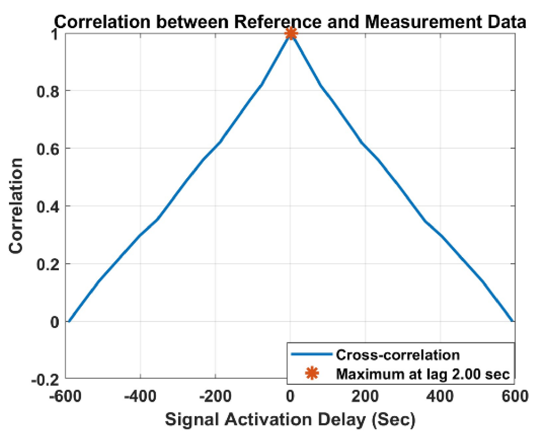
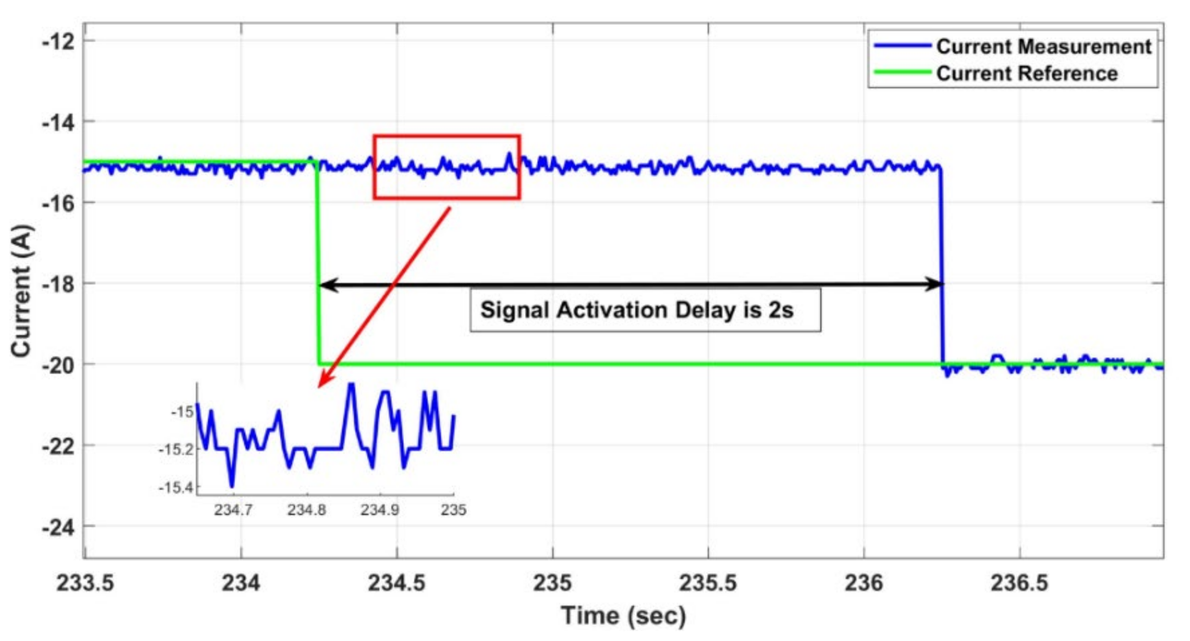
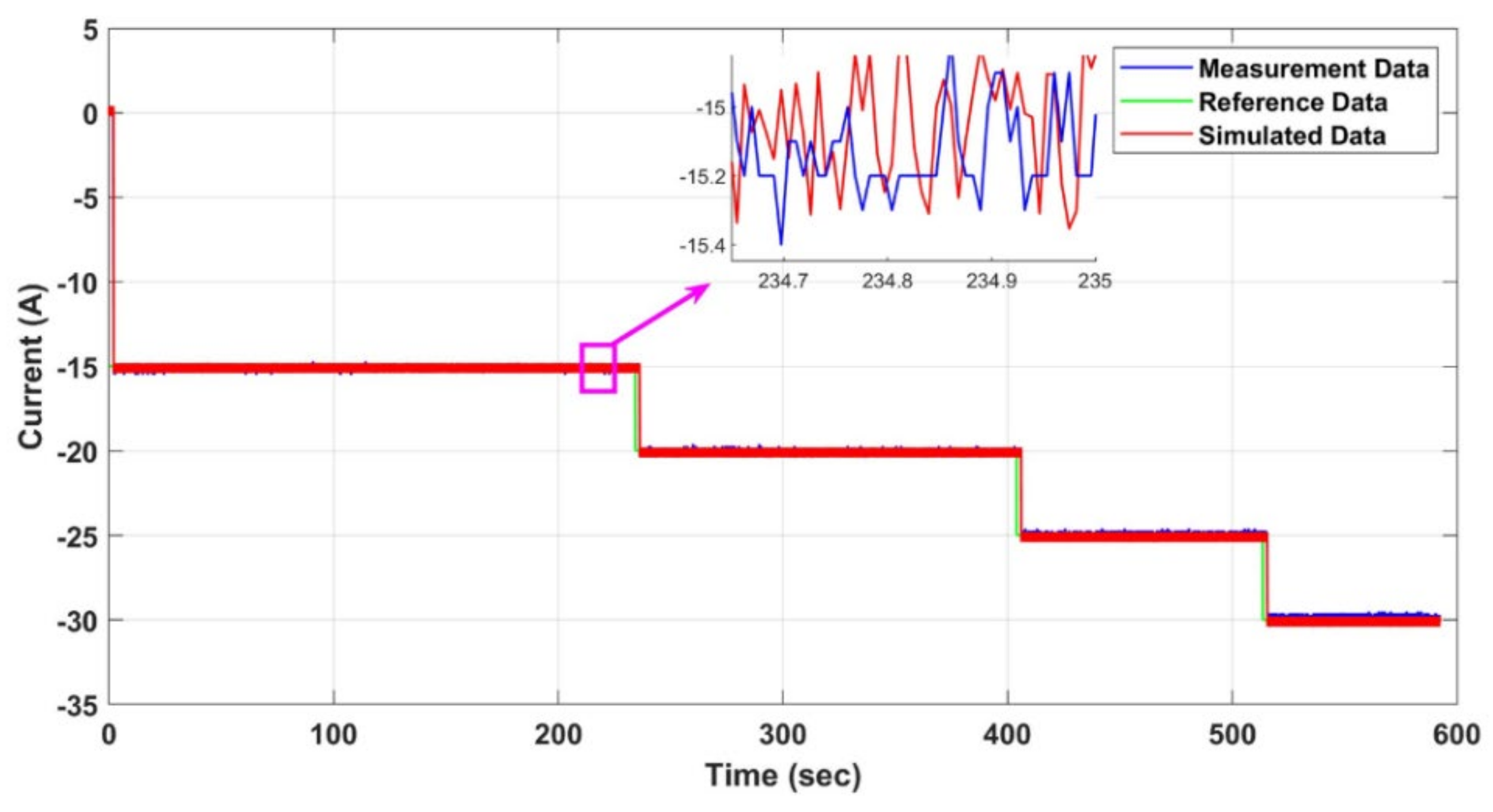
  • The response time is modeled as a transport delay, which is equal to 2 sec for the local control, which is shown in Figure 19.
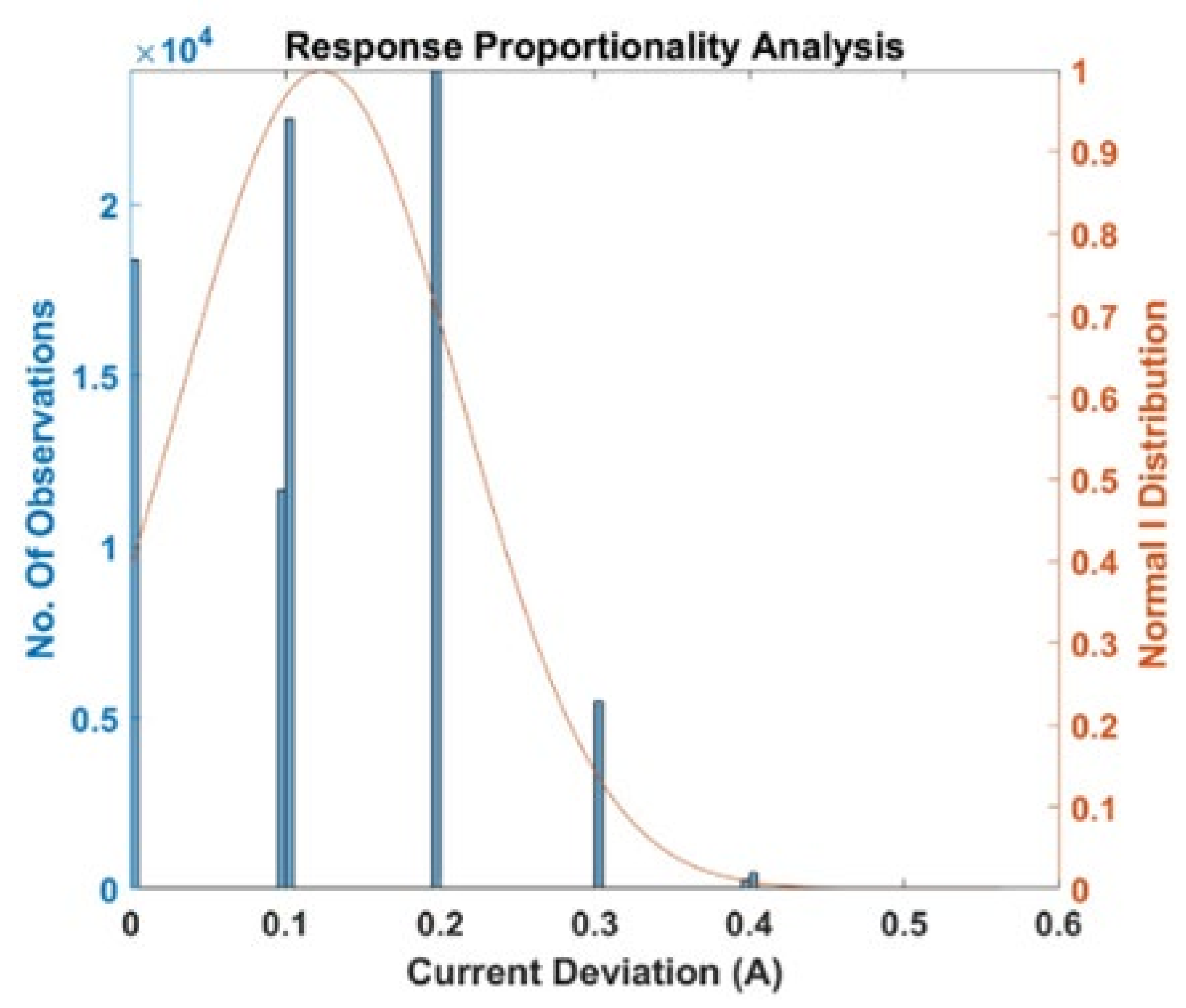
  • The setpoint proportionality is obtained by implementing Equation (1)
Y s p = K s p X s p r o u n d X s p K s p
where Xsp and Ysp are the non-truncated and truncated current signals, respectively. Moreover, the Ksp is a proportionality gain equal to around 0.5% of maximum current setpoint.
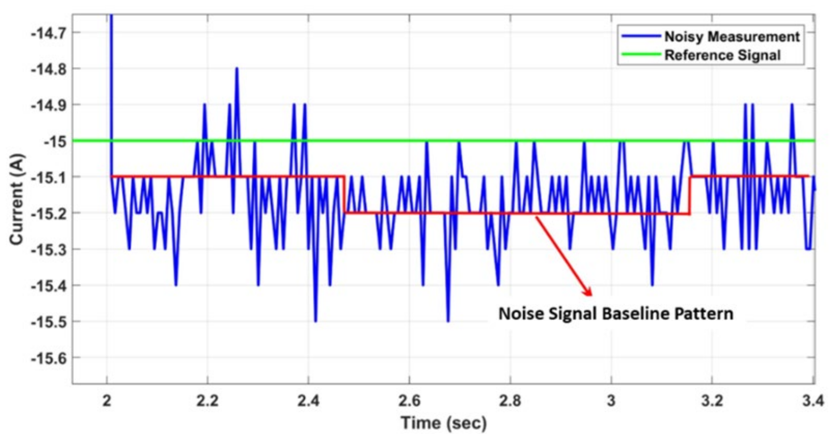
  • The relevant mean accuracy value, i.e., 0.2 A for a negative setpoint, is added to the current data points to perform the amplitude approximation. The implementation is obtained according to Equation (2):
Y m a = X m a + 0.67 %   o f   r a t e d   C u r r e n t
  • By including a uniformly distributed noise into the computed setpoint, the noise precision is accomplished. For a set-point ≠ 0, the noise typically has an amplitude of 0.3 A and 0.4 A. Equation (3) is used to determine the implementation.
Y n p = X n p + α 3 10
where during the duration of the simulation, it is a uniformly distributed random integer between −1 and +1.
The developed V2G charger model has been validated via simulations in MATLAB/Simulink using the requested current signals from real hardware controller, i.e., the green line in Figure 23. Results show that the simulated results (red line) match rather adequately the actual current measured (blue line) via following the input signal, which was the same green test pattern. Furthermore, Figure 24 shows the error signal between the actual and simulated current data. It can be noticed that the error density is higher within the a very small band, i.e., 0–0.5A (1.66% of the charger rated power). Ultimately, Figure 25 reports the error distribution function for the entire simulation time relying on MATLAB/Simulink. It can be noticed that the mismatches that occur between actual and simulated current data are within the band 0.2 A. In particular, the error distribution figure shows that more than 80% of the error lies within the 0–0.2 A band. For the information, it is possible to achieve a good approximation of the normalized errors’ distribution curve by using a normal distribution function with mean value m = 0.0385 A and standard deviation s = 0.235 A. The V2G facility test result of CHAdeMO and the Combo CCS Type 2 for EV charger application are compared in the Table 9 below.

6. Conclusions

In this paper, the technical feasibility of a commercial EV charger with V2G functionality with a Combo CCS Type 2 connector has been identified. The significance of initial SoC on the efficiency has been emphasized. It is found that the V2G efficiency with the Combo CCS Type 2 standard is around 97.7% at a 50% SoC level. The THD of the current level at the AC side is lower than 5%, which is IEC-1000-3-6 standard compliant. However, some noise is captured, which is the reason the current ripples around 0.3–0.5 A amplitude. The 0.1 A noise baseline offset is found during V2G power transfer. Furthermore, a data-driven model of the V2G charger has been developed by analyzing the testing data in a MATLAB/Simulink software environment. A thorough simulation research demonstrated the model’s correctness when implementing the flexibility product’s validated qualities. The suggested model is an illustration of how the results of hardware characterization tests may be used directly to construct realistic models that can be used for numerous further power system simulation activities.

Author Contributions

Conceptualization, S.J. and M.A.-M.; methodology, S.J.; software, S.J., O.H.G. and B.O.; validation, S.J., O.H.G., B.V. and B.O.; formal analysis, S.J.; investigation, S.J. and O.H.G. and B.V.; resources, S.J. and M.A.-M.; data curation, S.J.; writing—original draft preparation, S.J.; writing—review and editing, B.V., T.G., M.A.-M. and O.H.; visualization, S.J.; supervision, O.H.; project administration, O.H.; funding acquisition, O.H. All authors have read and agreed to the published version of the manuscript.

Funding

This research was funded by European Commission under grant number 875131 (eCharge4Driver project).

Institutional Review Board Statement

Not applicable.

Informed Consent Statement

Not applicable.

Acknowledgments

This work was supported by the Horizon 2020 Programme of the European Commission under grant agreement no. 875131 (eCharge4Driver project). We, as authors, also acknowledge Flanders Make for the support to our research group.

Conflicts of Interest

The authors declare no conflict of interest.

Abbreviations

ACESAdaptive Control of Energy Storage
ADRAutomatic Demand Response
CANController Area Network
CCSCombined Charging Service
CHAdeMOCHARGE de MOVE
CPOCharge Point Operator
DASDirect-Attached Storage
DHCPDynamic Host Configuration Protocol
DUTDevice Under Test
EVCAElectric Vehicle Charging Analyzer
EVCCElectric Vehicle Communication Controller
EVSEElectric Vehicle Supply Equipment
EXIEfficient XML Interchange
FCRFrequency Containment Reserves
G2VGrid-to-Vehicle
GB/TGuojia Biaozhun/Tuijian (China)
IECInternational Electromechanical Commission
IEEEInstitute of Electrical and Electronic Engineers
ISOInternational Organization of Standardization
JARIJapan Automotive Research Institute
JEVSJapan Electric Vehicle Standard
OCPPOpen Charge Point Protocol
OEMOriginal Equipment Manufacturer
PLCPower Line Communication
SAESociety of Automotive Engineers
SDPSECC Discovery Protocol
SECCSupply Equipment Communication Controller
SLAACStateless Address Auto-Configuration
TCPTransmission Control Protocol
THDTotal Harmonic Distortion
TLSTransport Layer Security
UDPUser Datagram Protocol
V2GVehicle-to-Grid
VCUVehicle Control Unit
XMLExtensible Markup Language

References

  1. EPA-United States Environmental Protection Agency. Sources of Greenhouse Gas Emissions. Available online: https://www.epa.gov/ghgemissions/sources-greenhouse-gas-emissions (accessed on 9 July 2022).
  2. Xiamen Joint Tech Co. Ltd., Ag. Advantages & Disadvantages of DC Charging Compared to AC Charging; Xiamen Joint Tech Co. Ltd., Ag: Xiamen City, China, 2022; Available online: https://www.linkedin.com/pulse/advantages-disadvantages-dc-charging-compared-ac-jointevse (accessed on 13 September 2022).
  3. Lauinger, D.; Vuille, F.; Kuhn, D. A review of the state of research on vehicle-to-grid (V2G): Progress and barriers to deployment. In Proceedings of the European Battery, Hybrid and Fuel Cell Electric Vehicle Congress, Geneva, Switzerland, 14–16 March 2017; pp. 1–8. [Google Scholar]
  4. Kempton, W.; Letendre, S.E. Electric vehicles as a new power source for electric utilities. Transp. Res. Part D Transp. Environ. 1997, 2, 157–175. [Google Scholar] [CrossRef]
  5. Bibak, B.; Tekiner-Moğulkoç, H. A comprehensive analysis of Vehicle to Grid (V2G) systems and scholarly literature on the application of such systems. Renew. Energy Focus 2021, 36, 1–20, ISSN 1755-0084. [Google Scholar] [CrossRef]
  6. Schmutzler, J.; Andersen, C.A.; Wietfeld, C. Evaluation of OCPP and IEC 61850 for Smart Charging Electric Vehicles. World Electr. Veh. J. 2013, 6, 863–874. [Google Scholar] [CrossRef] [Green Version]
  7. Bahrami, A. EV Charging Definitions, Modes, Levels, Communication Protocols and Applied Standards, Technical Report. Available online: https://www.researchgate.net/publication/338586995_EV_Charging_Definitions_Modes_Levels_Communication_Protocols_and_Applied_Standards/citations (accessed on 26 August 2022).
  8. Neaimeh, M.; Andersen, P.B. Mind the gap- open communication protocols for vehicle grid integration. Energy Inform. 2020, 3, 1–17. [Google Scholar] [CrossRef] [Green Version]
  9. Noel, L.; de Gerardo, Z.R.; Kester, J.; Sovacool, B.K. Vehicle-to-Grid: A Sociotechnical Transition beyond Electric Mobility; Springer: Cham, Switzerland, 2019. [Google Scholar]
  10. Virta Global. The Two Sides of EV Charging Network Operators. 2019. Available online: https://www.virta.global/blog/emsp-cpo-ev-charging-roles-responsibilities (accessed on 14 July 2022).
  11. Electric Vehicles, Volkswagen. Electric Vehicles | Volkswagen Newsroom. 2020. Available online: volkswagen-newsroom.com (accessed on 16 July 2022).
  12. Energy Informatics. Table 2 Protocols for Vehicle Grid Integration. 2020. Available online: https://energyinformaticsspringeropen.com/articles/10.1186/s42162-020-0103-1/tables/2 (accessed on 16 July 2022).
  13. V2G Global Roadtrip: Around the World in 50 Projects, Innovate UK. 2018. Available online: https://innovation.ukpowernetworks.co.uk/wp-content/uploads/2018/12/V2G-Global-Roadtrip-Around-the-World-in-50-Projects.pdf (accessed on 23 July 2022).
  14. Vehicle-to-Grid (V2G): Everything You Have to Know. Available online: https://www.virta.global/vehicle-to-grid-v2g (accessed on 23 July 2022).
  15. Schmidt, B. Volkswagen Wants to Stabilise the Grid by Adding V2G in All Its Electric Cars. The Driven, 7 April 2021. Available online: https://thedriven.io/2021/04/07/volkswagen-wants-to-stabilise-grid-by-adding-v2g-in-all-its-electric-cars (accessed on 23 July 2022).
  16. Hanley, S. Volkswagen Plans to Offer V2G and Plug&Charge Technology in 2022. Clean Technica, 23 December 2021. Available online: https://cleantechnica.com/2021/12/23/volkswagen-plans-to-offer-v2g-and-plug-charge-technology-in-2022 (accessed on 23 July 2022).
  17. Vehicle-to-Grid: Energy Storage on Wheels. EIT Innoenergy, 12 October 2021. Available online: https://www.eba250.com/vehicle-to-grid-energy-storage-on-wheels (accessed on 23 July 2022).
  18. ACES Project—Across Continents Electric Vehicle Services. 2017. Available online: https://www.aces-bornholm.eu (accessed on 16 July 2022).
  19. The Parker Project. 2016. Available online: https://parker-project.com (accessed on 16 July 2022).
  20. INVENT Project—Intelligent Electric Vehicle Integration. 2017. Available online: https://backend.orbit.dtu.dk/ws/portalfiles/portal/77554391/thesis_Peter_Bach_Andersen.PDF (accessed on 16 July 2022).
  21. Grid Motion Project—Reducing Electric Vehicle Usage Cost Thanks to Smart Charging Process. 2017. Available online: https://parker-project.com/wp-content/uploads/2018/12/VGI-Summit-Day-2-S2-Projects-Gridmotion.pdf (accessed on 16 July 2022).
  22. Industry Learning Reports. Available online: https://www.v2g-hub.com/reports (accessed on 24 July 2022).
  23. Wikipedia Contributors. CHAdeMO. Wikipedia, The Free Encyclopedia, 20 August 2022. Available online: https://en.wikipedia.org/w/index.php?title=CHAdeMO&oldid=1105514885 (accessed on 24 July 2022).
  24. Leemput, N.; Geth, F.; Juan Van, R.; Jeroen, B.; Johan, D.; Marinelli, M. Reactive power support in residential LV distribution grids through electric vehicle charging. Sustain. Energy Grids Netw. 2015, 3, 24–35. [Google Scholar] [CrossRef]
  25. Zecchino, A.; Marinelli, M. Analytical assessment of voltage support via reactive power from new electric vehicles supply equipment in radial distribution grids with voltage-dependent loads. Int. J. Electr. Power Energy Syst. 2018, 97, 17–27. [Google Scholar] [CrossRef]
  26. Arias, M.N.B.; Hashemi, S.; Andersen, P.B.; Træholt, C.; Romero, R. V2G Enabled EVs Providing Frequency Containment Reserves: Field Results. In Proceedings of the 2018 IEEE International Conference on Industrial Technology (ICIT 2018), Lyon, France, 20–22 February 2018; pp. 1–6. [Google Scholar]
  27. Yoshida, M.D.; Blech, T. CHAdeMO DC Charging: Successful Transition Towards Nation- and Region-Wide Zero-Emisson. CHAdeMO Association, April 2021. Available online: https://movelatam.org/portfolio-item/chademo-charging-protocol-for-electric-vehicles/ (accessed on 24 July 2022).
  28. Myles, B.; Robert, E. Making the right connections General procurement guidance for electric vehicle charge points. 2015. Available online: http://ukevse.org.uk/resources/procurement-guidance/ (accessed on 13 July 2022).
  29. Luyten, S.; Leemput, N.; Geth, F.; Van Roy, J.; Büscher, J.; Driesen, J. Standardization of Conductive AC Charging Infrastructure for Electric Vehicles. In Proceedings of the 22nd International Conference and Exhibition on Electricity Distribution (CIRED 2013), Stockholm, Sweden, 10–13 June 2013; Volume 2013. [Google Scholar] [CrossRef] [Green Version]
  30. Schwarzer, V.; Ghorbani, R. Current State-of-the-Art of EV Chargers; EVTC Electric Vehicle Transportation Centre: Cocoa, FL, USA, 2015; pp. 1–13. [Google Scholar]
  31. Quílez, M.G.; Abdel-Monem, M.; El Baghdadi, M.; Yang, Y.; Van Mierlo, J.; Hegazy, O. Modelling, analysis and performance evaluation of power conversion unit in G2V/V2G application-a review. Energies 2018, 11, 1082. [Google Scholar] [CrossRef] [Green Version]
  32. Cuma, M.U.; Tümay, M.; Yirik, E.; Ünal, E.; Dericioğlu, Ç.; Onur, B. A review of charging technologies for commercial electric vehicles. Int. J. Adv. Automot. Technol. 2018, 2, 61–70. [Google Scholar]
  33. China is Developing New GB/T Fast Charging Standard at 900kW. Insideevs Press Release, 19 Jun 2018. Available online: https://insideevs.com/news/338620/china-is-developing-new-gb-t-fast-charging-standard-at-900-kw (accessed on 13 September 2022).
  34. SAE International. SAE Electric Vehicle and Plug in Hybrid Electric Vehicle Conductive Charge Coupler; SAE International: Warrendale, PA, USA; Troy, MI, USA, 2013. [Google Scholar]
  35. International Electrotechnical Commission. Communication Networks and Systems for Power Utility Automation-Part 90-8: IEC 61850 Object Models for Electric Mobility; International Electrotechnical Commission: Geneva, Switzerland, 2014. [Google Scholar]
  36. Shin, M.; Kim, H.; Kim, H.; Jang, H. Building an Interoperability Test System for Electric Vehicle Chargers Based on ISO/IEC 15118 and IEC 61850 Standards. Appl. Sci. 2016, 6, 165. [Google Scholar] [CrossRef] [Green Version]
  37. Zecchino, A.; Thingvad, A.; Andersen, P.B.; Marinelli, M. Test and Modelling of Commercial V2G CHAdeMO Chargers to Assess the Suitability for Grid Services. World Electr. Veh. J. 2019, 10, 21. [Google Scholar] [CrossRef]
Figure 1. EV charging and V2G architecture with relevant communication standards [36].
Energies 15 07364 g001
Figure 2. DC charging test system architecture with Combo CCS Type 2 connector.
Energies 15 07364 g002
Figure 3. Passenger car to test the V2G using Combo CCS Type 2.
Energies 15 07364 g003
Figure 4. Additional VCU installation with necessary wiring and communication interfaces.
Energies 15 07364 g004
Figure 5. Required relay terminals to activate control of selected VCU.
Energies 15 07364 g005
Figure 6. The OSI 7-layer structure of ISO 15118.20 standard.
Energies 15 07364 g006
Figure 7. The communication request and response stream during charging/discharging test.
Energies 15 07364 g007
Figure 8. The software modification for V2G test.
Energies 15 07364 g008
Figure 9. Experimental setup for V2G test with BOSCH passenger car.
Energies 15 07364 g009
Figure 10. Measurement of DC voltage and current via CAN communication.
Energies 15 07364 g010
Figure 11. Measurement of AC voltage, current and power on the grid side. Here, Ig is grid current (Cyan), Vg is grid voltage (light green) and Pg is the instantaneous power (red).
Energies 15 07364 g011
Figure 12. Measurement of DC voltage and current with reference value via CAN communication over the full testing period.
Energies 15 07364 g012
Figure 13. Measurement of DC power discharging from the battery.
Energies 15 07364 g013
Figure 14. Grid current profile (20A/div) at 6.23 kW discharging power.
Energies 15 07364 g014
Figure 15. Grid current profile (50A/div) at 9.23 kW discharging power.
Energies 15 07364 g015
Figure 16. Estimated V2G efficiency at different initial battery SoC.
Energies 15 07364 g016
Figure 17. The correlation between reference and measurement current value.
Energies 15 07364 g017
Figure 18. Communication architecture implemented during V2G testing.
Energies 15 07364 g018
Figure 19. Panels of communication between real EV and EVSE.
Energies 15 07364 g019
Figure 20. Actual hardware response delay compared to the reference signal.
Energies 15 07364 g020
Figure 21. Measurement of noisy signal with the variable baseline.
Energies 15 07364 g021
Figure 22. Number of observations of measurement signal deviation from the reference.
Energies 15 07364 g022
Figure 23. Simulation model results compared to the reference and actual hardware measurement data.
Energies 15 07364 g023
Figure 24. Error between simulated and hardware measurement.
Energies 15 07364 g024
Figure 25. Measurement and simulated data error distribution function over the full testing period.
Energies 15 07364 g025
Table 1. European V2G test projects with corresponding connector standards [22].
ProjectsCountryConnector
Standard
Project
Duration
ParkerDenmarkCHAdeMO2016–2018
Redispatch V2GGermanyCHAdeMO2018–2021
CITY-ZENNetherlandCHAdeMO2014–2019
Smart Solar ChargingNetherlandCHAdeMO/CCS2014–2019
Grid MotionFranceCHAdeMO/CCS2017–2019
ACESDenmarkCHAdeMO2016-2018
Network Impact of Grid-Integrated VehicleUKCHAdeMO/CCS2017–2020
Porto SantoPortugalIEC 62196-2/CHAdeMO2015–2020
ZEMtoALLSpainCHAdeMO2012-2017
Vehicle-to-CoffeeGermanyIEC 62196-2/CHAdeMO2015–2018
NewMotion V2GNetherlandCHAdeMO2017
Amsterdam V2GNetherlandCHAdeMO2013–2017
SEEV4-City5 Cities in EUCHAdeMO2016–2020
SHAR-QGreeceIEC 62196-2/CHAdeMO2016–2019
Denmark V2GDenmarkCHAdeMO2016–Ongoing
Genoa PilotItalyCHAdeMO2017–Ongoing
UK Vehicle-2-Grid (V2G)UKCHAdeMO2016–Ongoing
GrowSmarterSpainCHAdeMO2016–2019
Table 2. IEC 62196-2 Connector Standard for AC charging [29].
IEC 62196-2Type 1Type 2Type 3
Coupler1-phase1-phase and 3-phase1-phase and 3-phase with shutters
Related standardSAE J1772 Type 1VDE-AR-E 26232-2-
Maximum current32 A (80 A at the US)70 A (1-phase)
63 A (3-phase)
16 A (1-phase)
32 A (3-phase)/63 A(3-phase)
Maximum voltage250 V480 V (3-phase)250 V/400 V
Maximum power19 kW43.5 kW22 kW (3-phase)
Pin and interlock5 pins, mechanic lock7 pins, electronic lock4 pins or 5 pins
Control pinTwo short pinsOne short, one long pin-
CommunicationPWM over CPPWM over CO-
Energies 15 07364 i001Energies 15 07364 i002Energies 15 07364 i003
Table 3. CHAdeMO connector characteristics [31].
Parameter DescriptionRated Values
Maximum current120 AEnergies 15 07364 i004
Maximum voltage500 V DC
Maximum power50 kW
Maximum current (control system)7 A
Maximum voltage (control system)12 V DC
Level of chargingDC level 3
Control pin7 pins
Communication protocolCHAdeMO (CAN communication)
Table 4. CHAdeMO pinout functionalities [32].
Pin IDWire Cross Section (mm2)Description
10.75GroundEnergies 15 07364 i005
20.75Start/stop charging 1
3 None
40.75Permission/prohibition charging
522 or 40DC supply negative
622 or 40DC supply positive
70.75Verification of the connector connection
80.75CAN High
90.75CAN Low
100.75Start/stop charging 2
Table 5. Main characteristics of Combo connectors Type 1 and type 2 [31].
ParametersCombo Type 1 (US)Combo Type 2 (EU)
Energies 15 07364 i006Energies 15 07364 i007
DC Charging
Maximum current150 A200 A
Maximum voltage600 V850 V
Charging mode44
Maximum power90 kW170 kW
Connector typeCombo 1 (IEC 62196-3)Combo 2 (IEC 62196-3)
AC Charging
Nominal current32 A70 A (1-phase)/63 A (3-phase)
Nominal voltage250 V230 V (1-phase)/400 V (3-phase)
Charging mode33
Maximum power13 kW44 kW
Connector typeType 1 (IEC 62196-2, SAE J1772)Type 2 (IEC 62196-2)
Table 6. Pin configuration and functionality of Combo connectors Type 1 and Type 2 [32].
PinFunctionsCommentsCombo Type 1
PPCommunication/Charging process controlProximity inletEnergies 15 07364 i008
CPControl pilot
PEEarth groundEV to earth ground
L1/NAC 1-phase chargingPhase 1/Neutral
L2Phase 2
DC+DC chargingDC positive terminal
DC-DC negative terminal
PinFunctionsCommentsCombo Type 2
PPCommunication/Charging process controlProximity inletEnergies 15 07364 i009
CPControl pilot
PEEarth groundEV to earth ground
L1AC 3-phase ChargingPhase 1
L2Phase 2
L3Phase 3
NNeutral
DC+DC ChargingDC positive terminal
DC-DC negative terminal
Table 7. Specification comparison of different DC charging connector standards [33].
SpecificationNew GB/TGB/TCHAdeMOCCS Type 1Tesla
Energies 15 07364 i010Energies 15 07364 i011Energies 15 07364 i012Energies 15 07364 i013Energies 15 07364 i014
Max Power900 kW237.5 kW400 kW400 kW135 kW
No. of Control Pilot20311
CommunicationCAN (SAE J1939)CAN (SAE J1939)CAN (ISO 11898)PLC (ISO 15118)CAN (SAE J2411)
+12 V Power SupplyYesOptionalYesNoNo
V2G CompatibleUnknownUnder R&DYesUnder R&DNo
Coupler LockInletConnectorConnectorInletInlet
AvailabilityChinaChina, IndiaGlobalEU, US, AGlobal
Related StandardsIEC 61851-23-1
IEC 61851-23-2
IEC 61851-23-1IEC 61851-23-1
IEC 61851-23-2
IEEE 2030.1
IEC 61851-23-1
SAE J1772
None
Cooling TechniqueLiquid-Cooled
Cable Under
Development
Liquid-Cooled
Cable Not
Available
Liquid-Cooled
Cable Under
Development
Liquid-Cooled
Cable Under
Development
Liquid-Cooled
Cable Discontinued
Table 8. The communication testing result with full stack ISO 15118 during V2G test.
Test NoContentsTargetProtocolResult
1Slack Parameter ExchangeEVCCSLACPass
2Signal Strength MeasurementEVCCSLACPass
3Logical Network Parameter ExchangeEVCCSLACPass
4Control Pilot Voltage RangeEVCCIEC 61851Pass
5Control Pilot Frequency RangeEVCCIEC 61851Pass
6Control Pilot Duty-Cycle RangeEVCCIEC 61851Pass
7SECC Discovery Protocol (SDP)EVCCISO 15118Pass
8Supported Application ProtocolEVCCISO 15118Pass
9Session Setup MessageEVCCISO 15118Pass
10Service DiscoveryEVCCISO 15118Pass
11Payment Service SelectionEVCCISO 15118Pass
12Payments DetailsEVCCISO 15118Pass
13AuthorizationEVCCISO 15118Pass
14Charge Parameter DiscoveryEVCCISO 15118Pass
15Cable CheckEVCCISO 15118Pass
16Pre-ChargeEVCCISO 15118Pass
17Power Delivery (Start)EVCCISO 15118Pass
18Current DemandEVCCISO 15118Pass
9Power Delivery (Stop)EVCCISO 15118Pass
20Welding DetectionEVCCISO 15118Pass
21Session StopEVCCISO 15118Pass
22Power Delivery (Negative)EVCCISO 15118Pass
Table 9. The V2G testing result between CHAdeMO and Combo CCS Type 2 charger connector standard.
Performance IndicesV2G Test with CHAdeMO [37]V2G Test with Combo CCS 2
Signal Activation Delay4 s2 s
Setpoint Linearity<4% (Power Setpoint 400 W)<1.5% (Current Setpoint 0.2 A)
Measurement Accuracy4.4% (Power measurement)2.56% (Current Measurement)
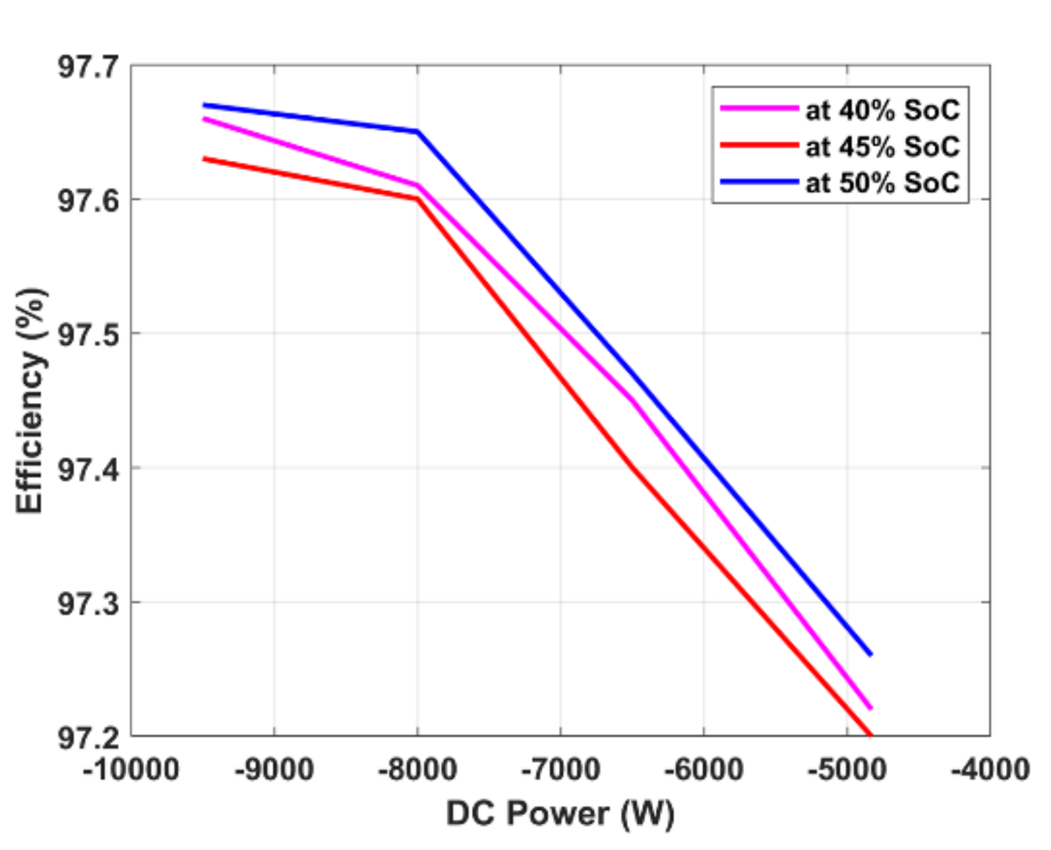
V2G Efficiency (@50% SoC and 8 kW Power Delivery)Around 93%Around 97%
Publisher’s Note: MDPI stays neutral with regard to jurisdictional claims in published maps and institutional affiliations.

