Article

Stationary Gas Dynamics and Heat Transfer of Turbulent Flows in Straight Pipes at Different Turbulence Intensity

1
Turbines and Engines Department, Ural Federal University, Str. Mira, 19, Yekaterinburg 620002, Russia
2
Ural Diesel-Motor Plant LLC, Str. Front Brigades, 18, Yekaterinburg 620017, Russia
*
Author to whom correspondence should be addressed.
Energies 2022, 15(19), 7250; https://doi.org/10.3390/en15197250
Submission received: 9 September 2022 / Revised: 24 September 2022 / Accepted: 27 September 2022 / Published: 2 October 2022
(This article belongs to the Special Issue Heat and Mass Transfer)

Abstract

:
The gas-dynamic and heat-exchange behaviours of air flows in gas-dynamic systems have a significant impact on the efficiency and environmental performance of most technical equipment (heat engines, power plants, heat exchangers, etc.). Therefore, it is a relevant task to obtain reliable experimental data and physical laws on the influence of cross-sectional shape and initial turbulence intensity on gas dynamics and the level of heat transfer. In this study, data were experimentally obtained on the instantaneous values of the local velocity and local heat transfer coefficients of stationary air flows in straight pipes with circular, square, and triangular cross-sections at different initial values of the turbulence intensity. The measurements were carried out with a constant temperature hot-wire anemometer, thermocouples, and pressure sensors. Based on the research results, data on the turbulence intensity and averaged local heat transfer along the length of pipes with different cross-sections were summarised. It has been established that turbulence intensity in a square pipe is up to 40% higher than in a round channel; in a triangular channel, on the contrary, it is up to 28% lower. After the air flow’s initial turbulence, the relaxation of the flow in square and triangular pipes occurs faster than in a round channel. It is found that the initial intensity of turbulence leads to an increase in the averaged local heat transfer, which is typical of all investigated pipe configurations and initial conditions.

1. Introduction

Turbulence intensity in gas flows has a significant effect on the flow structure, the features of boundary layer creation, hydraulic resistance, gas-dynamic parameters, and level of heat transfer in many technical applications [1]. Consequently, data on the influence of turbulence intensity on the thermal and mechanical features of flows can be used in turbine building, engine building, aircraft building, the energy sector, construction, and other related industries. By controlling turbulence intensity, it is possible to improve the aerodynamics of technical facilities, the flow characteristics of the inlet and outlet systems of turbines and engines, the quality of the mixture formation and combustion of combustible mixtures, and efficiency of heat exchangers and cooling systems. It is also possible to develop methods for designing buildings and ventilation.
There are several fundamental studies focused on the influence of turbulence intensity on gas dynamics and heat transfer of flows in various applications. J. Kestin et al. found that turbulence intensity influences the position of the flow separation point from the surface of the streamlined cylinder: with an increase in turbulence intensity from 0.005 to 0.23, an increase in the flow separation angle from 81 to 85° was recorded [2]. J. Kestin et al. also studied the level of heat transfer of the plate at values of ram air turbulence intensity ranging from 0.04 to 0.17 [3]. It was found that even small changes in the turbulence intensity of the oncoming flow cause large changes in the heat transfer coefficient (up to 40–150%). J. C. Simonich and P. Bradshaw experimentally showed that the level of plate heat transfer in free flow increases by about 5% for each rms increase in the turbulence’s longitudinal intensity [4]. R. MacMullin et al. [5,6] experimentally measured the velocity profile and wall temperature at different degrees of turbulence (from 0.07 to 0.18). They found that the level of heat transfer increases with increased turbulence intensity. At the same time, an increase in heat transfer took place up to a turbulence intensity value of 0.12, then a stabilisation of the heat transfer coefficient was observed up to a turbulence intensity value of 0.15: after this value, the heat transfer level slightly decreased. R. J. Moffat et al. [7] studied the effect of high-intensity large-scale gas flow turbulence on the boundary layer heat transfer for a curved surface. It was established that with increased turbulence intensity, there is an increase in the level of heat transfer. P. K. Maciejewski et al. [8] conducted similar studies to assess the effect of the degree of flow turbulence on the level of heat transfer in relation to the surface of a complex configuration (similar to turbine blades). It was established that a variation in turbulence intensity within 0.05–0.4 leads to a change in the level of heat transfer on the researched surface by ± 15%. Slanciauskaus and Pedesius [9] studied the influence of free flow turbulence intensity (from 0.011 to 0.135) on the level of heat transfer at a constant gas flow rate. There was an increase in the Nusselt number up to 20% with an increase in the initial intensity of flow turbulence. The works of the scientific group Terekhov V.I., Yarygin N.I., Dyachenko A. Yu., and others are highlighted [10,11]. They studied the gas dynamics and heat transfer of gas flows in separated flows. It was demonstrated that the initial turbulence intensity in gas flows has a significant impact on vortex formation and heat transfer in separated flows behind various obstacles.
There are also many modern applied studies on the effect of turbulence intensity on gas dynamics and heat transfer during gas flow in various applications. The combustion process control is one area in which various kinds of disturbances are used (including the initial turbulence of air and combustible media) [12,13,14,15]. Thus, S. Wang et al. studied the change in the nature of flame propagation under various perturbations [12]. The authors identified various gas-dynamic factors that influence combustion process parameters, such as the intensity of the flame turbulence, squeeze velocity, and pressure rise rate. L. Chang and A. S. Rangwala studied the dynamics of combustion of a small layer of oil on a water surface at different turbulence intensities [13]. It is shown that an increase in turbulence intensity led to an increase in the heat transfer rate on the oil–water interface and reduced the combustion rate. S.-C. Yen et al. proposed a way to increase the efficiency of mixing air and fuel (methane) by changing the structure of the flow behind the blast nozzle [14]. The increase in turbulence intensity led to a reduction in CO2 emissions, a reduction in flame length by almost 44%, and doubling of integral combustion capacity.
Turbulence intensity also has a significant impact on the physical mechanism of the cooling of gas turbine blades [16,17,18,19]. Z. Ren et al. studied the flow characteristics and level of heat transfer of turbine blades with microroughness (microchannels) to disturb the flow [16]. It was possible to achieve an increase in the heat transfer coefficient of up to 300% compared to the basic version of the blades, along with a decrease in pressure losses by 3–6%. Similar results were obtained by N. Halder et al. [17]. They managed to increase the efficiency of film cooling by 61–97% by controlling the intensity of turbulence in the gas flows. Based on experimental studies and numerical analysis, S. Baek et al. examined the secondary flow and flow non-uniformity in the internal cooling serpentine channel inside a gas turbine’s blades under various initial gas-dynamic conditions [18]. It was shown that a high initial flow irregularity can increase heat transfer.
Turbulence intensity also has a significant impact on the thermal and mechanical processes in internal combustion engines [20,21,22,23]. X. Zhao et al. studied the influence of vortices and turbulence intensity in the intake system and engine cylinder on mixture creation processes and the working medium combustion [20]. It was established that for different types of engines, there are certain optimal levels of turbulence and turbulence intensity at which the engine has maximum efficiency and environmental friendliness. The turbulence intensity affects the quality of mixture formation of fuel and air in the combustion chamber, the rate of mixing of the fuel–air mixture, the rate of fuel evaporation, the level of heat exchange of the flow with the walls of gas exchange systems, and engine cylinder. Optimum levels of turbulence intensity are determined individually for each engine and depend on a large number of factors: engine size, turbocharging system, channel and pipeline geometry, etc. K. Masera and A. K. Hossain developed an original swirl chamber in the intake system that controlled the gas-dynamic characteristics of gas flows in a piston engine in order to reduce harmful emissions in the exhaust gases [21]. It was shown that the use of a swirl chamber leads to a reduction in CO and NOx emissions by up to 15% compared to the basic intake system. C. Gößnitzer and S. Givler developed a new mathematical model of a piston engine operating cycle that takes into account turbulence intensity in gas exchange systems in order to reduce operational irregularities from cycle to cycle [22]. This model makes it possible to find sources of non-uniformity and improves the quality of forecasting the thermodynamic parameters of an engine.
Turbulence intensity should be taken into account when designing and improving the combustion chambers of power plants [24,25,26]. D. Sellan and S. Balusamy used the PIV method to study the flow structure in different configurations of gas turbine combustion chambers with an emphasis on vortex structures and turbulence intensity [24]. The authors propose a method for controlling the flame parameters to improve the combustion chamber’s environmental performance. S. B. Sasongko et al. developed a device for mixing stream jets [25]. The authors managed to substantially scale up turbulence intensity, which led to a significant improvement in the ability to disperse and mix the jet fluid.
Turbulence intensity should be taken into account in many physical processes. For example, the flow turbulence level is measured when a mixture of methane and air explodes [27], the intensity of turbulence influences noise values during gas streaming [28], the effect of turbulence intensity on pedestrians is taken into account when laying out buildings [29] and ventilation system development [30], and turbulence intensity affects the measurement accuracy of various laboratory systems [31,32,33,34].
Thus, studying the effect of turbulence intensity on the thermal and mechanical characteristics of gas flows in various applications is a relevant objective. It should be noted that to date, the effects of turbulence intensity on the gas-dynamic and heat transfer characteristics of flows in pipelines with various cross-sectional shapes (circle, square, triangle) have not been sufficiently studied. The structure of the gas flow in square and triangular channels differs significantly from the flow in a pipe with a circular cross-section (stable, longitudinal vortex (secondary) flows occur in the corners of profiled channels) [35]. Consequently, these vortex flows can have a significant effect on the thermal and mechanical characteristics of gas flows in pipes with various configurations. Based on pilot studies and a literature review, the key objectives of the research were formulated:
To develop a test stand and select measuring instruments for studying the gas dynamics and heat transfer of stationary air flows in straight pipes with different cross-sections (circle, square, equilateral triangle);
to obtain test data on the instantaneous values of the local velocity and local heat transfer coefficient of a stationary air flow along the length of profiled straight pipes at different initial values of turbulence intensity;
to evaluate the influence of the initial flow turbulence on turbulence intensity and the value of the local heat transfer coefficient of the air flow along the length of a straight pipe with circular, square, and triangular cross-sections.

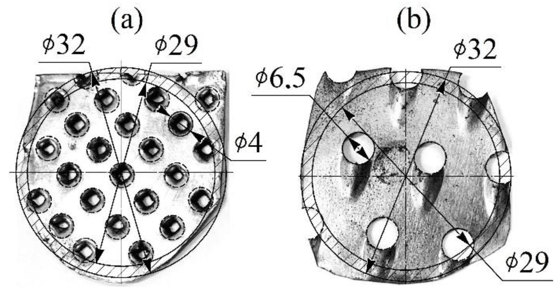
2. Description of the Test Facility and Methodology

The target of the research was stationary gas flows moving in straight pipes with different cross-sections, such as a circle, square, and equilateral triangle. The working medium in the experiments was air with a temperature of 21 ± 1 °C. The experiments were carried out at a barometric pressure of 98 ± 0.2 kPa. The average air flow velocity w ranged from 5 ± 0.125 to 75 ± 1.875 m/s. Accordingly, the Reynolds numbers were in the range 8800 < Re < 1,750,005 (this is the turbulent regime for the investigated pipes). Air movement was created by a pump at the outlet of the tube under research.
The pipe length was 1000 mm. The geometric dimensions of the pipe cross-sections were based on the equality of the areas. The round pipe’s inner diameter was 29 mm, the side of the square pipe was 25.5 mm, and the triangular pipe was 39 mm. Correspondingly, the cross-sectional areas were 658 ± 6 mm2 for all pipes under study. The inner surface of the investigated pipes had an average roughness of 6.3 µm. The pipes had three control sections at distances of 100 mm, 300 mm, and 500 mm (Figure 1). The choice of distances between the control sections was due to the fact that measurements should be carried out evenly to the middle of the pipe.
To create the initial level of flow turbulence, plate-type static turbulators were used (Figure 2).
They were installed in the inlet section in front of the test pipes. The distance from the turbulator to the pipe inlet was 50 mm (this distance determines the level of flow turbulence and requires additional study). The values of the initial turbulence intensity ranged from 0.02 (pipe without turbulator) to 0.12 (with an accuracy of ±5.5%). The base value of the air flow’s initial intensity turbulence was determined from the first section in a round pipe. In this research, turbulence intensity TI was determined as the ratio of the root-mean-square fluctuating velocity component to the average velocity of the flow in the pipe [36]. The turbulence intensity (TI) is defined based on the stream-wise RMS velocity. The time interval of 0.5 s (about 1000 instantaneous velocity values) was used to calculate the TI.
During the experiments, the following physical quantities were determined: local flow velocity wx, local heat transfer coefficient αx, air temperature t, and barometric pressure po. A constant temperature hot-wire anemometer was used to determine wx and αx. For this, two types of sensors were used (Figure 3). The sensors had one thread. When determining the flow velocity’s instantaneous values, a filament sensor (the filament length was 5 mm; the diameter was 5 μm) located approximately in the centre of the channel (perpendicular to air flow direction) was used. The values of the average air flow velocity in the pipes were determined as the ensemble expectation of the function wx = f (τ). When determining the instantaneous values of the local heat transfer coefficient αx, a sensor with a thread was also used, located on a fluoroplastic substrate flush with the wall of the channel. The local heat transfer coefficient αx is determined with indirect calibration by using known empirical dependencies, i.e., without direct calculation of the thermal flow taken from the sensor thread. The determination of the αx was based on indirect calibration. During calibration, stationary heat transfer in a long straight pipe (l/d ≥ 50) was chosen. Thus, the calibration consisted of correlating the calculated heat transfer coefficient α (W/(m2 K)) for a long straight pipe and the value of the signal from the hot-wire anemometer sensor U (V). This method is described in detail in [37]. Consequently, the average value of the local heat transfer coefficient in the control section was calculated as the ensemble expectation of the function αx = f (τ). The output signals from the hot-wire anemometer were sent to an analogue-to-digital converter and then transferred to a computer for processing.
Barometric pressure po was measured by a mercury barometer with a relative standard uncertainty of 0.2%. The average flow temperature was measured with a thermocouple with a relative standard uncertainty of 1.5%. The relative standard uncertainty in determining the flow rate wx was 5.2%, and the local heat transfer coefficient αx was 10.9%. Methods for determining physical quantities are detailed in [37,38].

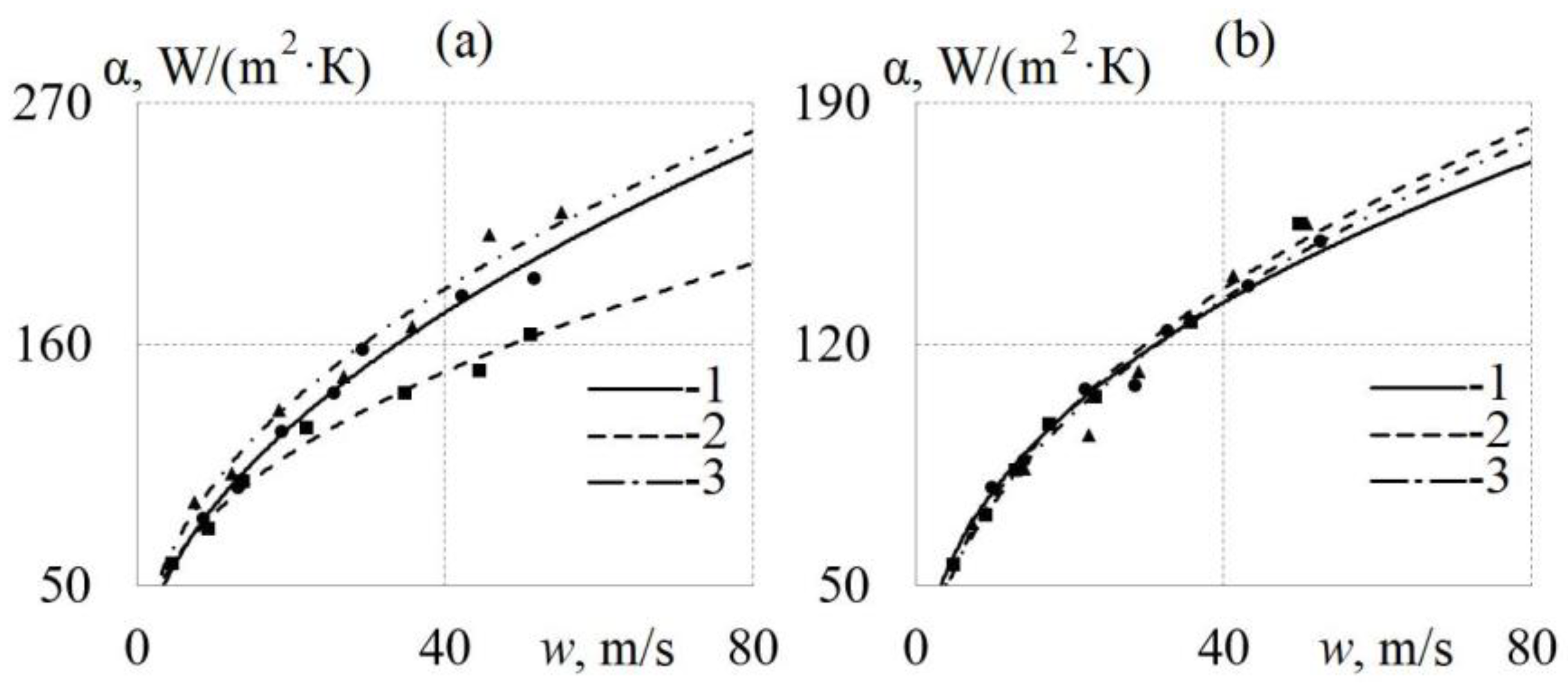
3. Gas-Dynamic Characteristics of Air Flow in Profiled Channels at Different Turbulence Intensities

As expected, the initial flow turbulence leads to a noticeable change in the function wx = f (τ), which is typical of all the cross-sectional shapes in question (Figure 4). It was established that the amplitudes of air flow velocity fluctuations in a round pipe are ±3 m/s when the turbulence intensity TI changes from 0.02 to 0.12. However, such a change in TI leads to a change in the pulsation amplitudes by approximately ±2 m/s for square and triangular pipes (Figure 4). This indirectly indicates a faster relaxation of the flow in the profiled pipes, i.e., faster stabilisation of the air flow rate’s pulsating components. Active flow relaxation in profiled pipes can be associated with stable vortex structures in square and triangular channels [39,40]. These vortex structures form at the corners of the profiled pipes and prevent fluctuations in the core of the flow.
Figure 5 shows the change in the intensity of turbulence TI of the air flow along the length of the pipes at different velocities and without initial turbulence.
At a distance of 100 mm, the turbulence intensity TI in a square pipe is 10–40% higher than in a round channel (Figure 5a). This indicates pronounced pulsation components in the square channel due to vortices in the corners of the square, which has an impact on the flow core (the hot-wire anemometer sensor is roughly in the pipe’s centre). This trend is maintained at all air flow rates. Differences in TI values between round and square pipes decrease downstream and reach 5–20% at a distance of 300 mm (Figure 5b).
The opposite pattern can be traced if the values of the turbulence intensity of the air flow in round and triangular pipes are compared. It was found that at a distance of 100 mm, TI in a triangular pipe is 10–28% less than in a round channel (Figure 5a). Consequently, it can be concluded that the vortices at the corners of the triangle have a stabilising effect on the air flow core. This trend also remains at all air flow rates in triangular and round pipes. Differences in TI values between round and square tubes decrease downstream and reach 5–7% at a distance of 300 mm, which is within experimental uncertainty (Figure 5b). Accordingly, the vortex structures in a triangular channel are stronger and more stable than in a square one. Therefore, the pulsating component of the velocity in the triangular channel is smoothed out noticeably faster.
The change in turbulence intensity TI along the length of the pipes for different initial flow turbulences can be seen in Figure 6. It can be seen from Figure 6a that in the absence of initial flow turbulence, turbulence intensity TI along a square pipe is 5–40% higher compared to a round channel. At the same time, at a distance of 300 mm, the differences in TI are actually levelled, which is typical for all cross-sections. The opposite trend can be recorded when comparing TI along the length of round and triangular pipes. The turbulence intensity in a triangular pipe is 7–28% lower compared to a round channel (Figure 6a). The differences in the patterns of TI = f (lч) for a square pipe from the basic round and triangular ones may be related to the peculiarities of the formation of vortex structures in the corners of a square channel (undoubtedly, this requires additional research). The established patterns can be used in the design of heat exchangers, the gas-air paths of heat engines, and ventilation systems. Figure 6b shows that after the initial flow turbulence, the relaxation of the flow in profiled pipes occurs faster than in a round channel. Thus, in the first control section, turbulence intensity TI in the square and triangular channels is 30–40% less than in the round channel; in the second control section, the differences in TI values are reduced by 15–20%; in the third control section, the TI values are virtually the same for all pipe configurations. The main reason for the damping of the pulsating velocity components in the flow core in profiled pipes is the vortex structure. These structures perturb the flow in the corners of the square and triangle, but prevent fluctuations in the flow centre.
Therefore, the shape of a straight pipe’s cross-section has a significant impact on the gas-dynamic features (turbulence intensity, amplitude of flow velocity pulsations, flow characteristics, and hydraulic resistance) during the initial turbulence of stationary air flows. Accordingly, it can be assumed that changed gas-dynamic conditions will influence the level of heat transfer in profiled pipes.

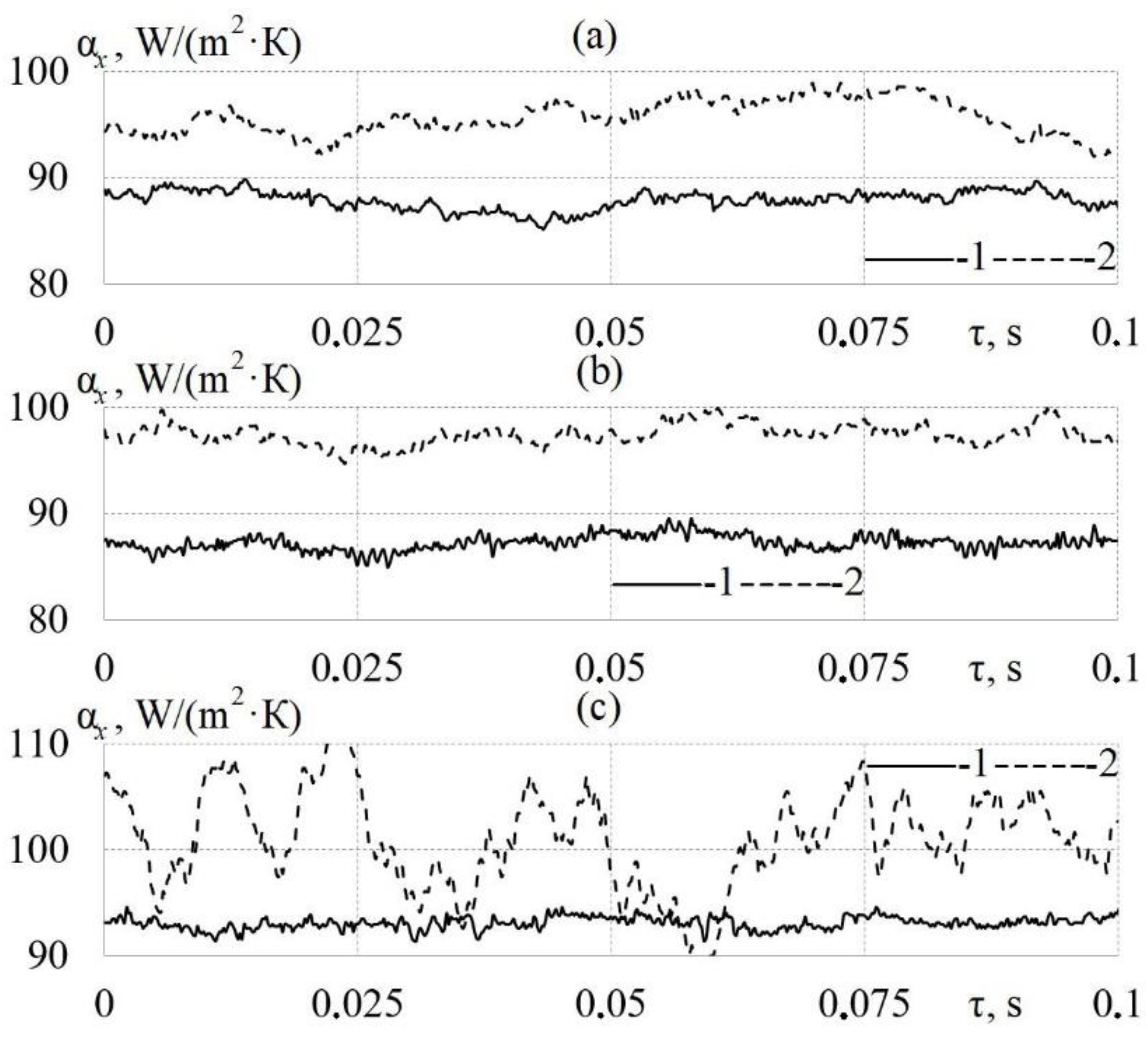
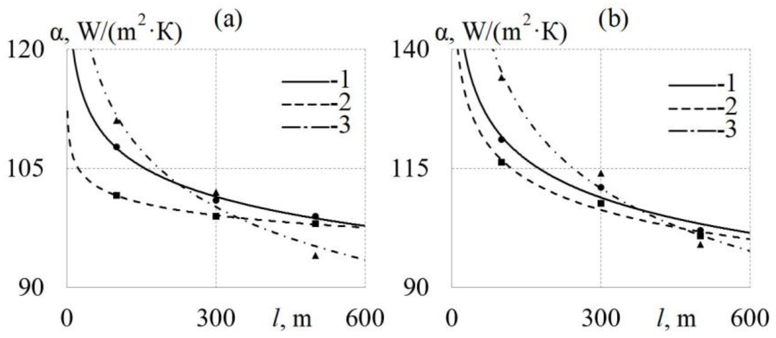
4. Heat Transfer Characteristics of Air Flow in Profiled Channels at Different Turbulence Intensities

Figure 7 shows the effect of the initial turbulence intensity on the instantaneous values of the local heat transfer coefficient αx in straight pipes with different cross-sections. The initial flow turbulence in a round pipe leads to an increase in the amplitudes of the local heat transfer coefficient within 12% (Figure 7a). In this case, TI has no effect on the shape of the curve αx = f (τ). Similar patterns also occur for a square pipe (Figure 7b). The initial turbulence intensity has a noticeable effect on the shape of the curve αx = f (τ) for the triangular pipe (Figure 7c). This may be due to the influence of vortex structures at the corners of the triangular channel, which in this tube configuration occasionally penetrate the boundary layer. A slight intensification of the heat transfer for different pipe configurations leads the flow to relax, which contributes to the creation of a stable boundary layer and a corresponding increase in local heat transfer between the flow core and the near-wall flow.
Figure 8 shows the dependences α = f (τ) for straight pipes with different cross-sections without initial flow disturbance. In the absence of initial flow turbulence, the use of a triangular pipe leads to a slight intensification of local heat transfer within 9% (lx = 100 mm) compared to a round channel (Figure 8a). The opposite effect can be recorded for air flows in a square pipe: local heat transfer is suppressed up to 7% (lx = 100 mm) in comparison with a round channel (Figure 8a). It should be noted that in the control section at a distance of 300 mm, the differences in the averaged values of the local heat transfer coefficient do not exceed 5%, which is within experimental uncertainty (Figure 8b).
Then, Figure 9 shows the dependences α = f (τ) along the length of straight pipes with different cross-sections, taking into account the initial flow turbulence. Figure 9a shows that when using a square tube, local heat transfer is suppressed up to 25% (lx = 100 mm) compared to a round channel. There are practically no differences in the values of the averaged local heat transfer coefficient in round and triangular pipes in the section lx = 100 mm (Figure 9a). In the control section at a distance of 300 mm, the values of the averaged local heat transfer coefficient are approximately the same (differences within 1–6%) for all the pipe configurations (Figure 9b). Based on this, it can be concluded that the initial flow turbulence has a noticeable effect on the level of heat transfer, although not along the entire length of the pipes. Therefore, it is important to evaluate the change in local heat transfer along the full length of profiled pipes.
Figure 10 shows the dependencies α = f (lx) for straight pipes with different cross-sections and gas-dynamic conditions. At an average air rate of w = 20 m/s in the absence of initial flow turbulence, the following patterns of changes in local heat transfer along the length of straight pipes are observed (Figure 10a):
In a triangular tube up to a distance of about 250 mm, heat transfer is enhanced (within 10%) compared to a round channel; further, in contrast, there is a suppression of α up to 18%, if the level of heat transfer in the triangular and round pipes is compared;
when air flows in a square pipe, the level of local heat transfer is 1–25% lower than in a round pipe for the entire channel length;
as the air flow relaxes, the differences in the levels of heat transfer in square and triangular pipes gradually level out and approach the values of the local heat transfer coefficient characteristic of a round channel.
Similar patterns of changes in local heat transfer along the length of straight pipes are qualitatively preserved in the presence of an initial flow disturbance (Figure 10b). There are only quantitative differences in the values of local heat transfer.
The identified patterns of changes in local heat transfer along the length of straight pipes are qualitatively preserved in the entire studied range of flow rates and initial flow intensities. In particular, Figure 11 additionally shows the functions α = f (lx) for straight pipes with different cross-sections at w = 40 m/s. With an increase in the average velocity, the maximum values of the averaged local heat transfer coefficient increase (Figure 11). However, the general pattern of change in α along the length of the pipes remains virtually unchanged, as well as for the velocity w = 20 m/s.
Thus, it has been established that the shape of the channel cross-section and the initial turbulence intensity have significant effects on the gas-dynamic and heat-exchange characteristics of steady-state air flows. Differences in the values of TI and α can reach 40% for different pipe cross-sections and different initial conditions. These thermal-mechanical characteristics of flows should be taken into account when designing technical equipment.

5. Conclusions

Based on the conducted research, the following key conclusions are drawn:
  • Dependences of the instantaneous values of the air flow’s local velocity wx and the local heat transfer coefficient αx in time are obtained for the initial turbulence intensity TI from 0.02 to 0.12 along the length of pipes with different cross-sections.
  • The influence of the shape of the pipe cross-section on the gas-dynamic and heat-exchange characteristics of steady-state air flows has been established:
    The intensity of turbulence TI in a square pipe is up to 40% higher than in a round channel; in a triangular channel, in contrast, it is up to 28% lower;
    in a triangular pipe, up to a distance of about 250 mm, there is an increase in α within 10% compared to a round channel, which is then replaced by a decrease of up to 18%;
    when air flows in a square pipe, the level of local heat transfer is up to 25% lower than in a round pipe throughout the studied range of the channel length.
  • The influence of initial turbulence intensity on the thermal and mechanical characteristics of steady-state flows in pipes with various cross-sections is shown:
    After the initial flow turbulence, relaxation of the flow in the square and triangular pipes occurs faster than in the round channel;
    as the air flow relaxes, the differences in the heat transfer in square and triangular pipes gradually level out and approach the local heat transfer coefficient typical of a round channel;
    the initial turbulence intensity leads to an increase in the averaged local heat transfer, which is typical of all studied pipe configurations and initial conditions.
  • The data obtained can be useful in the design of heat exchangers, gas-air systems of heat engines, ventilation and air conditioning systems, shipbuilding, and aircraft building. For example, the configuration of gas-exchange systems and the perfection of their internal processes largely determine the specific parameters of heat engines [41].
  • Future research on this topic may be related to studying the influence of the configuration of pipelines and initial gas-dynamic conditions in relation to pulsating gas flows, since many technical units operate in a cyclic mode.

Author Contributions

Conceptualization, L.P.; methodology, L.P. and N.G.; software, L.O.; validation, L.O. and N.G.; formal analysis, L.O. and N.G.; investigation, V.S. (Vladimir Slednevand) and V.S. (Vladislav Shurupov); resources, L.P.; data curation, L.P.; writing—original draft preparation, L.P., N.G. and L.O.; writing—review and editing, L.P.; visualization, V.S. (Vladimir Slednevand) and V.S. (Vladislav Shurupov); supervision, L.P.; project administration, L.P. All authors have read and agreed to the published version of the manuscript.

Funding

The research funding from the Ministry of Science and Higher Education of the Russian Federation (Ural Federal University Program of Development within the Priority-2030 Program) is gratefully acknowledged.

Data Availability Statement

Not applicable.

Conflicts of Interest

The authors declare no conflict of interest.

Nomenclature

wxlocal air velocity, m/s
waverage flow velocity, m/s
αxlocal heat transfer coefficient, W/(m2 · K)
αaverage heat transfer coefficient, W/(m2 · K)
pobarometric pressure, kPa
ttemperature, °C
dpipeline diameter, mm
llinear dimension, mm
TIturbulence intensity

References

  1. Terekhov, V.I. Heat Transfer in Highly Turbulent Separated Flows: A Review. Energies 2021, 14, 1005. [Google Scholar] [CrossRef]
  2. Kestin, J.; Wood, R.T. The influence of turbulence on mass transfer from cylinders. J. Heat Transf. 1971, 93, 321–327. [Google Scholar] [CrossRef]
  3. Kestin, J.; Maeder, P.F.; Wang, H.E. Influence of turbulence on the transfer of heat from plates with and without a pressure gradient. Int. J. Heat Mass Transf. 1961, 3, 133–154. [Google Scholar] [CrossRef]
  4. Simonich, J.C.; Bradshaw, P. Effect of free-stream turbulence on heat transfer through a turbulent boundary layer. J. Heat Transf. 1978, 100, 671–677. [Google Scholar] [CrossRef]
  5. MacMullin, R.; Elrod, W.; Rivir, R. Effects of free stream turbulence from a circular wall jet on a flat plate heat transfer and boundary layer flow. Am. Soc. Mech. Eng. 1988, 11521. [Google Scholar]
  6. MacMullin, R.; Elrod, W.; Rivir, R. Free-stream turbulence from a circular wall jet on a flat plate heat transfer and boundary layer flow. J. Turbomach. 1989, 111, 78–86. [Google Scholar] [CrossRef]
  7. Moffat, R.J.; Maciejewski, P.K. Effects of very high turbulence on convective heat transfer. NASA Conf. Publ. 1984, 381–388. [Google Scholar]
  8. Maciejewski, P.K.; Moffat, R.J. Heat transfer with very high free-stream turbulence: Part II—Analysis of results. J. Heat Transf. 1992, 114, 834–839. [Google Scholar] [CrossRef]
  9. Slanciauskaus, A.; Pedesius, A. Effect of Free-stream Turbulence on the Heat Transfer in the Turbulent Boundary Layer. In Proceedings of the International Heat Transfer Conference, Toronto, ON, Canada, 7–11 August 1978. [Google Scholar]
  10. Smylsky, Y.I.; Terekhov, V.I.; Yarygina, N.I. Heat transfer in turbulent separated flow behind a rib on the surface of square channel at different orientation angles relative to flow direction. Int. J. Heat Mass Transf. 2012, 55, 726–733. [Google Scholar] [CrossRef]
  11. D’yachenko, A.Y.; Terekhov, V.I.; Yarygina, N.I. Vortex formation and heat transfer in turbulent flow past a transverse cavity with inclined frontal and rear walls. Int. J. Heat Mass Transf. 2008, 51, 3275–3286. [Google Scholar] [CrossRef]
  12. Wang, S.; Xiao, G.; Wang, W.; Mi, H. Study of the process of deflagration flame behavior in disturbance conditions. Exp. Therm. Fluid Sci. 2022, 139, 110710. [Google Scholar] [CrossRef]
  13. Chang, L.; Rangwala, A.S. Experimental study of crude oil slick burning on a turbulent water surface. Combust. Flame 2022, 241, 112119. [Google Scholar] [CrossRef]
  14. Yen, S.-C.; Ye, C.-E.; San, K.-C. Effects of starlike control discs on flow structures and combustion capability. Energy 2021, 225, 120276. [Google Scholar] [CrossRef]
  15. Ren, X.; Ju, X.; Gollner, M.J. Effect of freestream turbulence on the structure of boundary-layer flames. Combust. Flame 2022, 236, 111750. [Google Scholar] [CrossRef]
  16. Ren, Z.; Yang, X.; Lu, X.; Li, X.; Ren, J. Experimental investigation of micro cooling units on impingement jet array flow pressure loss and heat transfer characteristics. Energies 2021, 14, 4757. [Google Scholar] [CrossRef]
  17. Halder, N.; Saha, A.K.; Panigrahi, P.K. Enhancement in Film Cooling Effectiveness Using Delta Winglet Pair. J. Therm. Sci. Eng. Appl. 2021, 13, 4049427. [Google Scholar] [CrossRef]
  18. Baek, S.; Ryu, J.; Bang, M.; Hwang, W. Flow Non-Uniformity and Secondary Flow Characteristics Within a Serpentine Cooling Channel of a Realistic Gas Turbine Blade. J. Turbomach. 2022, 144, 091002. [Google Scholar] [CrossRef]
  19. Tao, Z.; Guo, Z.; Song, L.; Li, J. Uncertainty Quantification of Aero-Thermal Performance of a Blade Endwall Considering Slot Geometry Deviation and Mainstream Fluctuation. J. Turbomach. 2021, 143, 111013. [Google Scholar] [CrossRef]
  20. Zhao, X.; Liu, R.; Wang, H.; Zheng, Z.; Yao, M. Effects of charge motion on knocking combustion under boosted high load condition of a medium-duty gasoline engine. Fuel 2022, 326, 125040. [Google Scholar] [CrossRef]
  21. Masera, K.; Hossain, A.K. Modified selective non-catalytic reduction system to reduce NOx gas emission in biodiesel powered engines. Fuel 2021, 298, 120826. [Google Scholar] [CrossRef]
  22. Gößnitzer, C.; Givler, S. A new method to determine the impact of individual field quantities on cycle-to-cycle variations in a spark-ignited gas engine. Energies 2021, 14, 4136. [Google Scholar] [CrossRef]
  23. Plotnikov, L.V.; Zhilkin, B.P.; Brodov, Y.M. The Influence of Piston Internal Combustion Engines Intake and Exhaust Systems Configuration on Local Heat Transfer. Procedia Eng. 2017, 206, 80–85. [Google Scholar] [CrossRef]
  24. Sellan, D.; Balusamy, S. Experimental Investigation of Turbulent Flow/Flame Structure of Double Swirler Burner. In Advances in Energy and Combustion; Springer: Singapore, 2022; pp. 223–240. [Google Scholar]
  25. Sasongko, S.B.; Huang, R.F.; Hsu, C.M. Modulating flow and mixing characteristics of an inclined jet in crossflow at a large backward inclination angle by acoustic excitation. Int. J. Mech. Sci. 2021, 209, 106708. [Google Scholar] [CrossRef]
  26. Wang, C.; Wang, C.; Xie, J.; Khan, M.S. Influence Mechanism of Gas–Containing Characteristics of Annulus Submerged Jets on Sealing Degree of Mixing Zone. Processes 2022, 10, 593. [Google Scholar] [CrossRef]
  27. Bradley, D.; Lawes, M.; Morsy, M.E. Combustion-induced turbulent flow fields in premixed flames. Fuel 2021, 290, 119972. [Google Scholar] [CrossRef]
  28. Rahmani, E.; Fattahi, A.; Karimi, N.; Hosseinalipour, S.M. A comparative analysis of the evolution of compositional and entropy waves in turbulent channel flows. Phys. Fluids 2022, 34, 017103. [Google Scholar] [CrossRef]
  29. Yang, Y.; Zhang, T.; Xie, H.; Wang, X. Impacts of building layout on pedestrian level wind comfort and gas pollutant diffusion. J. Air Pollut. Health 2021, 6, 117–134. [Google Scholar] [CrossRef]
  30. Ozbakis, Y.; Erzincanli, F. Air flow control valve development with reinforced operating parameters. Surf. Rev. Lett. 2021, 28, 2150124. [Google Scholar] [CrossRef]
  31. Qiu, Y.; Chen, H.; Li, W.; Wu, F.; Li, Z. Optimization of the tracer particle addition method for PIV flowmeters. Processes 2021, 9, 1614. [Google Scholar] [CrossRef]
  32. Ge, M.; Manikkam, P.; Ghossein, J.; Kumar Subramanian, R.; Coutier-Delgosha, O.; Zhang, G. Dynamic mode decomposition to classify cavitating flow regimes induced by thermodynamic effects. Energy 2022, 254, 124426. [Google Scholar] [CrossRef]
  33. Ge, M.; Zhang, G.; Petkovšek, M.; Long, K.; Coutier-Delgosha, O. Intensity and regimes changing of hydrodynamic cavitation considering temperature effects. J. Clean. Prod. 2022, 338, 130470. [Google Scholar] [CrossRef]
  34. Ge, M.; Petkovšek, M.; Zhang, G.; Jacobs, D.; Coutier-Delgosha, O. Cavitation dynamics and thermodynamic effects at elevated temperatures in a small Venturi channel. Int. J. Heat Mass Transf. 2021, 170, 120970. [Google Scholar] [CrossRef]
  35. Kutateladze, S.S. Fundamentals of the Theory of Heat Transfer; Atomizdat: Moscow, Russia, 1979; p. 416. (In Russian) [Google Scholar]
  36. Plotnikov, L.V. Thermal-mechanical characteristics of stationary and pulsating gas flows in a gas-dynamic system (in relation to the exhaust system of an engine). Therm. Sci. 2022, 26, 365–376. [Google Scholar] [CrossRef]
  37. Plotnikov, L.; Plotnikov, I.; Osipov, L.; Slednev, V.; Shurupov, V. An Indirect Method for Determining the Local Heat Transfer Coefficient of Gas Flows in Pipelines. Sensors 2022, 22, 6395. [Google Scholar] [CrossRef]
  38. Plotnikov, L.V.; Zhilkin, B.P. Specific aspects of the thermal and mechanic characteristics of pulsating gas flows in the intake system of a piston engine with a turbocharger system. Appl. Therm. Eng. 2019, 160, 114123. [Google Scholar] [CrossRef]
  39. Plotnikov, L.V. Unsteady gas dynamics and local heat transfer of pulsating flows in profiled channels mainly to the intake system of a reciprocating engine. Int. J. Heat Mass Transf. 2022, 195, 123144. [Google Scholar] [CrossRef]
  40. Emery, A.F.; Neighbors, P.K.; Gessner, F.B. The numerical prediction of developing turbulent flow and heat transfer in square duct. J. Heat Transf. 1980, 102, 51–57. [Google Scholar] [CrossRef]
  41. Plotnikov, L.V. Experimental research into the methods for controlling the thermal-mechanical characteristics of pulsating gas flows in the intake system of a turbocharged engine model. Int. J. Engine Res. 2022, 23, 334–344. [Google Scholar] [CrossRef]
Figure 1. Photo (a) and scheme (b) of the test stand: 1—entrance section; 2—place of installation of the turbulator; 3—investigated pipeline with different cross-sections; 4—hot-wire anemometer of constant temperature; 5—analogue-to-digital converter; 6—laptop with software; 7—pump; 8—air flow control system; I, II, III—control section number.
Energies 15 07250 g001
Figure 2. Photos of turbulators with main dimensions: (a) turbulator to create turbulence intensity TI ≈ 0.08; (b) turbulator for TI ≈ 0.12.
Energies 15 07250 g002
Figure 3. Pipe cross-sections with main dimensions and sensor installation locations: (a) round; (b) square; (c) equiangular triangle.
Energies 15 07250 g003
Figure 4. Dependences of the instantaneous values of the local (lx = 100 mm) velocity wx in time at the intensity of the flow turbulence TI = 0.02 (1) and TI = 0.12 (2) in pipes with different cross-sections: (a) round (average velocity w ≈ 13 m/s); (b) square (w ≈ 13 m/s); (c) triangle (w ≈ 12 m/s).
Energies 15 07250 g004
Figure 5. Dependences of turbulence intensity TI on average air velocity w in round (1), square (2), and triangular (3) pipes without a turbulator (average TI = 0.02) for control sections: (a) lx = 100 mm; (b) lx = 300 mm.
Energies 15 07250 g005
Figure 6. Dependences of turbulence intensity TI along the length of (1) round, (2) square, and (3) triangular pipes for average air velocity w = 20 m/s and at initial values TI: (a) TI = 0.02; (b) TI = 0.12.
Energies 15 07250 g006
Figure 7. Dependences of the instantaneous values of the local (lx = 100 mm) heat transfer coefficient αx over time at the flow turbulence intensity TI = 0.02 (1) and TI = 0.12 (2) in pipes with different cross-sections: (a) round (average rate w ≈ 13 m/s); (b) square (w ≈ 13 m/s); (c) triangle (w ≈ 12 m/s).
Energies 15 07250 g007
Figure 8. Dependences of the local heat transfer coefficient α on the average air velocity w in round (1), square (2), and triangular (3) pipes without a turbulator (average TI = 0.02) for different control sections: (a) lx = 100 mm; (b) lx = 300 mm.
Energies 15 07250 g008
Figure 9. Dependences of the local heat transfer coefficient α on the average air velocity w in round (1), square (2), and triangular (3) pipes with a turbulator (TI = 0.12) for different control sections: (a) lx = 100 mm; (b) lx = 300 mm.
Energies 15 07250 g009
Figure 10. Dependences of the local heat transfer coefficient α along the length of round (1), square (2), and triangular (3) pipes for average air velocity w = 20 m/s and at initial values TI: (a) TI = 0.02; (b) TI = 0.12.
Energies 15 07250 g010
Figure 11. Dependences of the local heat transfer coefficient α along the length of (1) round, (2) square, and (3) triangular pipes for average air velocity w = 40 m/s and at initial values TI: (a) TI = 0.02; (b) TI = 0.12.
Energies 15 07250 g011
Publisher’s Note: MDPI stays neutral with regard to jurisdictional claims in published maps and institutional affiliations.

