Abstract
The currently reported bottom water sealing materials and fracturing technologies can hardly simultaneously achieve the high production and low water cut of gas reservoirs due to the complexity of various formation conditions. Therefore, without controlling the fracturing scale and injection volume, a kind of polylactide polymer water plugging material with a density of 1.15–2.0 g/cm3 is developed, which can be used to seal the bottom water of a gas–water differential layer by contact solidification with water and automatic degradation with natural gas. This technology can not only fully release the production capacity of the gas reservoir but also effectively control water production and realize the efficient fracturing development of the target gas reservoir. Laboratory test results show that the smart plugging agent has a bottom water plugging rate of 100%, and the low-density plugging agent has a dissolution rate of 96.7% in methane gas at 90 °C for 4 h and a dissolution rate of 97.6% in methane gas at 60 °C for 6 h, showing remarkable gas degradation performance. In addition, settlement experiments show that the presence of a proppant can increase the settlement rate of a plugging agent up to many times (up to 21 times) in both water and guanidine gum solution. According to the actual conditions of well J66-8-3, a single-well water plugging fracturing scheme was prepared by optimizing the length of fracture, plugging agent dosage, and plugging agent sinking time, and a post-evaluation method was proposed. It has guiding significance to the development of similar gas reservoirs.
1. Introduction
The discovery of unconventional oil and gas resources not only increased the potential of global oil and gas resources but also changed the world energy structure and helped to solve short-term energy crises [1,2,3]. As an important reservoir stimulation technology, hydraulic fracturing ensures the stable production of oil and gas fields [4,5,6].
At present, most unconventional oil and gas reservoirs in China are characterized by high water content and low permeability [7,8]. The separation between water and oil and gas layers is thin, and the pressure difference between reservoirs is small [9,10]. Thus, the high water production caused by hydraulic fracturing becomes another significant problem [11]. Therefore, conventional fracturing methods were mainly used to control the height of the fracture [12,13], avoid connecting the water layer, and carry out the small-scale and low-displacement fracturing technology [14]. These methods can control the height of fractures to a certain extent and avoid direct contact between water and oil layers. However, after fracturing, the fractures are shorter and the reservoir permeability is lower. In addition, the barrier between the gas and water layers is thin, and the stress difference between the reservoir and the barrier layer is small. Even if the scale and displacement are reduced in the fracturing process, controlling the propagation of fractures is extremely difficult, and pressing through the water layer is still easy.
In recent years, fracturing technology has made breakthrough progress with the advances in intelligent materials and computer technology (including intelligent optimization of fracturing parameters, intelligent monitoring of fracturing fractures, and so on) [15,16,17]. Many bottom water sealing materials have been applied in the field, and the water production rate of fractured oil and gas wells has been effectively controlled. Xu prepared a new expansion particle profile control agent, and laboratory test results attest to the strong plugging ability of the plugging agent [18]. Moreover, physical simulation tests and field applications were used to verify the plugging ability and plugging strength of the expandant bottom water fracturing technology on pores to ensure the performance of the expandant bottom water fracturing fluid. Through the dynamic simulation and data analysis of a field oil well, it has been previously found that there is a point-like or segmented water producing section in the horizontal section of the well, which produces water from the edge and bottom. On this basis, a highly selective gel was developed, which entered deep into the reservoir to plug the fracture, causing the pressure in the tube to slowly rise. The well maintained fluid production at 27 t/d after fracturing, increased oil production from 4 to 20 t/d, and reduced the water cut from 75% to 25% [19]. Zhang et al. studied segmented water search and water plugging technology [20]. First, a horizontal well was segmented reasonably, and then the water layer was determined using the designed intelligent equipment (due to the different properties of oil and water and the different temperature of different positions, water can be found intelligently by capturing the change in water pressure and temperature). Then, the water was cut off from the determined layers. This technology can effectively and intelligently selectively shut off water, which provides a more effective method for delaying the influx of bottom water and further improving oil recovery. Zhao et al. reported a new precipitator for fracturing and measured the settling velocity, plugging capacity, and conductivity of the new precipitator barrier and compared these with those of six other commonly used settling agents [21]. Filtration tests showed that the new settling agent could form a barrier and has a strong plugging effect on the fracturing fluid. Qi et al. developed a foam gel system that uses polyacrylamide as the main agent and contains the in situ heating system of nitrite and ammonium [22]. The foam gel has good water plugging ability due to volume expansion, and its performance can be controlled by adjusting the pH value to meet the different configuration requirements of different reservoirs.
However, the currently reported bottom water sealing materials so far have different advantages and disadvantages due to the complexity of various formation conditions, summarized in Table 1.

Table 1.
Summary of partial plugging materials.
To sum up, the main problems are as follows:
- (1)
- Unifying the water control between fracturing stimulations and bottom water is difficult [30,31]. Without fracturing, there is low or no production, and fractures communicate with water layers after fracturing.
- (2)
- Simply controlling the fracture height cannot solve the problems of water control and bottom water simulation [32]. For instance, the small-scale fracture control mode still has high water production after fracturing.
- (3)
- The existing traditional fracturing plugging agents may block water but also gas and hinder gas production during water control [33].
Therefore, we put forward in this work a new bottom water plugging fracturing material to try to solve the above problems. Without controlling the fracturing scale and injection volume, a water-blocking material that solidifies in contact with water and automatically degrades in contact with natural gas was developed to block the bottom water of gas–water differential layers. While fully releasing the production capacity of gas reservoirs, the technology can effectively control water and increase gas production and achieve the efficient fracturing development of gas reservoirs in a target area. Experimental test results show that the bottom water sealing rate of this intelligent plugging agent reaches 100% and that it has great degradation performance in the presence of natural gas. The construction was improved according to the water plugging fracturing field test, and a post-fracturing evaluation method was put forward.
2. Experimental Materials and Methodology
2.1. Experimental Materials
Pyrophosphoryl chloride (Cl4O3P2, Mn = 251.76) was obtained from Chongqing Chuandong Chemical Co., Chongqing, China, and p-hydroxybenzaldehyde (C7H6O2, Mn = 122.12), toluene (C7H8, Mn = 92.14), and sodium borohydride (NaBH4, Mn = 37.83) were purchased from Qianyan Science and Technology Co., Hong Kong. Lactide (C6H8O4, Mn = 144) was obtained from Suzhou Qihang Biotechnology Co., Suzhou, China, stannous isooctylate (C16H30O4Sn, Mn = 405.10) was obtained from Hubei Chunshuo Chemical Co., Zhijiang, China, and proppant (20/40 mesh ceramsite) was purchased from Guanghan Huitong Plastic Co., Deyang, China.
2.2. Flowchart of Laboratory Experiment
The synthesis and performance testing of the gas-soluble plugging agent is the key to verify the performance of the plugging agent. The first is the synthesis of the plugging agent, and then the synthetic plugging agent needs curing performance test, solubility test, and settlement experiment, respectively. An initial diverting capacity test of proppant is required prior to the curing performance test. Various laboratory experiments of plugging agent are shown in Scheme 1.
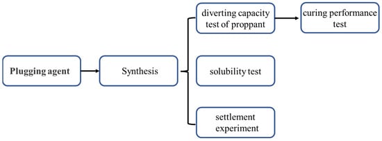
Scheme 1.
Flowchart of laboratory experiment.
2.3. Synthesis of the Plugging Agent
The gas-soluble plugging agent is a type of plugging agent that is soluble in natural gas and is injected into the formation with the proppant. It is solidified by water under the formation temperature condition. This can reduce the water-phase permeability of artificial fractures and increase the shielding ability and pressure resistance strength between gas and water layers to control the bottom water from flowing up along artificial fractures and leading to a large amount of water flowing out of gas wells. At the same time, the plugging agent dissolves when it comes into contact with natural gas, which restores the conductivity of proppant fractures and plays a dual role in controlling the bottom water of gas reservoirs and ensuring the normal production of natural gas. For this purpose, the laboratory synthesized a plugging agent material that solidifies in water and dissolves in gas. The 1 mol pyrophosphoryl chloride and 4 mol p-hydroxybenzaldehyde react in toluene to produce intermediate with aldehyde group. The aldehyde group is directly reduced to hydroxyl group by adding sodium borohydride. Finally, a highly branched poly (lactide) polymer was synthesized with lactide catalyzed by stannous isooctylate. The main synthesis route is shown in Scheme 2.
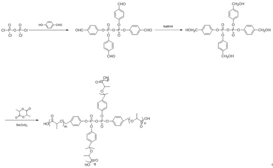
Scheme 2.
Synthesis of plugging agent.
The plugging agent was synthesized using solution polymerization, and the reactor is shown in Figure 1.
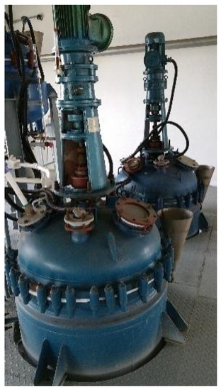
Figure 1.
Plugging agent synthesis reactor.
2.4. Diverting Capacity Test of Proppant
The main purpose of the experiment is to study the curing performance of the plugging agent system. Thus, the initial permeability of the fracture should be measured first. The experiment of diverting capacity test of proppant was based on methods previously reported by researchers, and the specific experimental steps are as follows:
- (1)
- Prepare the diversion chamber (Figure 2) for the experimental test without filling the proppant, and move it to the experimental test platform to ensure that the diversion chamber is placed horizontally to ensure uniform stress loading. Install the displacement sensor on the test platform, open the hydraulic press to load a closing stress of 1 MPa to ensure that the parts fit tightly, and set the data on the displacement meter test panel to zero.
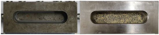 Figure 2. Diversion chamber before and after the placement of the plugging agent and proppant.
 - (2)
- Load the closing stress of the hydraulic press under a predetermined pressure, and record the displacement gauge data to obtain the diversion chamber deformation under the predetermined pressure. Then, record the average value as h1.
- (3)
- After the pressure relief, add a mixture of the plugging agent and a ceramic particle to the diversion chamber (Figure 1) under a predetermined sand paving concentration, and record the original sand thickness h2 using vernier calipers. Move the diversion chamber to the experimental test platform and pressurize to 1 MPa. Load the displacement sensor and set it to zero to record the height of the four corners.
- (4)
- Connect the differential pressure sensor and inlet and outlet pipeline of the diversion chamber to ensure that the valves are closed. Open the displacement pump to suppress the pressure of the diversion chamber. Control the displacement of the displacement pump at 30 mL/min and suppress the pressure of the diversion chamber to 2 MPa. During this period, check whether there is leakage in each pipeline.
- (5)
- After ensuring that each line is well sealed, open the vacuum pump to evacuate the line for more than 30 min. Then, open the displacement pump to saturate the fracture and line with the test fluid (simulating formation water).
- (6)
- Test the proppant conductivity step by step under pressure. When the proppant is pressured to the predetermined closing stress, use the vernier caliper to record the height of the four corners and the data of the displacement gauge to obtain the total deformation h3 under the predetermined closing stress, thus obtaining the proppant thickness = h2 − h3 + h1 in the diversion chamber under the predetermined closing pressure.
- (7)
- Open the conductivity test program, input the parameters of the experiment, and then switch to the experimental test window to start the diversion capacity test.
- (8)
- Adjust the advection pump to the set test flow rate, test the permeability within 30 min, and record the fluid quality, diversion chamber pressure, and flow pressure difference along the fracture.
- (9)
- After the test, close the advection pump, open the drain valve of the hydraulic press, unload the oil pressure, remove the pipeline of the diversion chamber, and take out the proppant in the diversion chamber and the diversion chamber.
- (10)
- According to the permeability calculation formula in the “Recommended Method for Short-term Conductivity Evaluation,” solve for the original permeability K under predetermined pressure and sand paving concentration (Equation (1)):
2.5. Curing Performance Test
Curing with water is one of the properties of the plugging agent. The following steps were completed to further explore the curing ability of the plugging agent.
- (1)
- Fill the diversion chamber with the plugging agent and proppant.
- (2)
- Connect the appropriate pressure sensor and import and export pipeline of the bypass chamber to ensure that each valve is in a closed state. Open the displacement pump to suppress the pressure of the diversion chamber. Control the displacement of the displacement pump at 30 mL/min and suppress the pressure of the diversion chamber to 2 MPa. During this period, check whether there is leakage in each pipeline.
- (3)
- After ensuring that the pipelines are well sealed, open the vacuum pump to evacuate the pipelines for more than 30 min. Then, open the displacement pump to saturate the cracks and pipelines with the test fluid (distilled water).
- (4)
- Heat the diversion chamber and set the formation temperature (60 °C or 90 °C).
- (5)
- Open the hydraulic pressurizer to load the closure stress of the diversion chamber, and stop pressurizing when the pressure rises to the initial pressure of the experimental design, ensuring that the pressure stability time is more than 30 min. Continue heating for n hours (heating time determined by melting and consolidation tests).
- (6)
- Check the plugging agent breakthrough pressure step by step. When the outlet end of the continuous liquid outflow shows that the plugging agent has been broken, the highest pressure is the highest breakthrough pressure (maximum plugging strength) of the plugging agent.
After the plugging agent breakthrough, continue forward flooding to simulate formation water. Then, measure the water-phase permeability K within 30 min after the breakthrough to obtain the temporary plugging rate, as shown in Equation (2):
where Z represents the temporary plugging rate (%), K represents the original water-phase permeability (μm2), and K1 represents the post-plugging permeability (μm2).
- (7)
- If the displacement pressure reaches 20 MPa and still does not break, shut off the pump.
- (8)
- After the test is completed, close the advection pump, unload the oil pressure, remove the pipeline of the diversion chamber, and take out and observe the diversion chamber.
2.6. Solubility Test
The gas solubility experiment is a key experiment to evaluate whether a plugging agent can be automatically degraded by gas. The evaluation methods and steps adopted in this study are as follows:
- (1)
- Add the liquid (fracturing fluid) into the plugging agent, stir it, and then put it into an oven for curing. Take the solidified plugging agent as the basic sample.
- (2)
- Take a proper amount of the solidified sample and put it into a sealable glass bottle filled with distilled water.
- (3)
- Drive the distilled water in the glass bottle with methane gas so that the solidified sample is completely immersed in methane gas.
- (4)
- Place the glass bottle in a water bath and set it to the formation temperature to heat.
- (5)
- Take out the plugging agent every 1 h and weigh it to calculate the dissolution. Repeat steps 2–4 to obtain the dissolution of each plugging agent every hour until the plugging agent weight changes almost no more.
- (6)
- Calculate and analyze the dissolution of the different plugging agents at different formation temperatures and times.
Note: proppant was not included in the plugging agent mentioned above because it is not possible to calculate the plugging agent dissolution rate accurately after the addition of proppant. Therefore, pure plugging agent was used.
2.7. Settlement Experiment of the Plugging Agent
The proppant settlement experiment was used for reference to simulate the underground fracture situation, and the settlement law of the water plugging material alone in the fracturing fluid and mixed with proppant was measured.
- (1)
- Measure the plugging agent and proppant with different volume ratios.
- (2)
- Shake well the plugging agent and proppant to mix them evenly.
- (3)
- Add water (or a guanidine gum solution) into the mixture of the plugging agent and proppant and simulate the mixing of the two in the sand mixing truck.
- (4)
- Add the mixture of the plugging agent and proppant to a graduated cylinder filled with water (or a guanidine gum solution) and calculate the settling rate.
2.8. Preparation of Fracturing Fluid
The guanidine gum base fluid prepared for laboratory testing and the fracturing fluid formulation used in the well J66-8-3 are shown below:
Base liquid: 0.42% guanidine gum (HPG) +1.0% anti-expansion agent +0.1% fungicide +0.5% foaming agent +0.2% drainage aid +0.2% Na2CO3. Cross-linking agent: cross-linking agent A:B = 100:6, the cross-linking ratio is 100:0.3.
The preparation method is carried out according to Chinese oil and gas standard SY/T 5107-2016 (water-based fracturing fluid performance evaluation method).
3. Results and Discussion
3.1. Research on Plugging Agent
In order to prove the successful synthesis of the polymer plugging agent, the final product poly (lactide) was analyzed by mass spectrometry.
As can be seen from Figure 3, the mass number corresponding to the peak with the largest mass number of the mass spectrum (that is, the molecular ion peak) is also greater than the molecular mass of various monomers and intermediates, thus confirming the successful synthesis of the polymer.
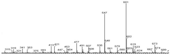
Figure 3.
Mass spectrometry of polymers.
3.2. Performance of the Water Plugging Material
3.2.1. Consolidation Test
- Diversion capacity of the proppant.
Measuring the original permeability of fractures is necessary to study the curing performance of the plugging agent. A 20/40-mesh ceramsite with a bulk density of 1.65 g/cm3 (apparent density of 3.0 g/cm3) was used to test the permeability and diversion capacity of the proppant (pure proppant and its placement in the diversion chamber are shown in Figure 4). These provide the calculation basis for the plugging efficiency of the plugging agent. Because temperature has almost no effect on the diversion capacity of pure proppant, the test temperature was the normal temperature.
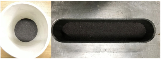
Figure 4.
Pure proppant and its placement in the diversion chamber.
The permeability and diversion capacity of the proppant at different closing pressures are shown in Figure 5. It can be found that the formation permeability and proppant conductivity both decrease with the increase in closure pressure. This is because the fracture tends to heal with the increase in formation closure pressure, resulting in smaller fractures and lower permeability, which affects proppant conductivity. From the test results, we found that the permeability of the 20/40-mesh ceramsite is 68.9 D at a 45 MPa closure pressure.
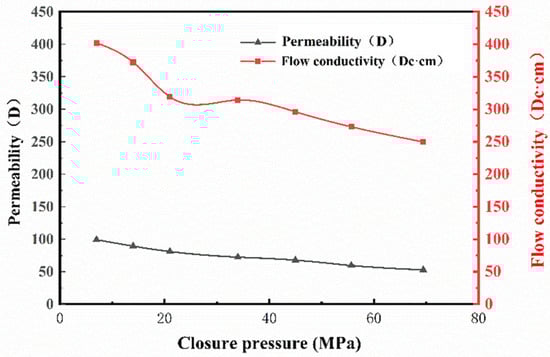
Figure 5.
Permeability and diversion capacity of pure proppant at different closure pressures.
- Plugging performance evaluation.
Different groups were tested to determine the cure and plugging ability of the plugging agent and proppant mixture at different densities. The densities and ratios of the plugging agent to the proppant are shown in Table 2.
Table 2.
Parameters of the different experimental groups.
A total of 50 mL of the plugging agent and proppant were measured in various volume ratios. Then, reagents were poured into the beaker, stirred evenly, and weighed 32.25 g, with a sand paving concentration of 5 kg/m2. A guanidine gum solution and glue breaker (guanidine gum concentration: 0.42%; glue breaker dosage: 0.04%) were added into the plugging agent and then put into the diversion chamber. Then, the curing ability of the plugging agent was tested. The bonding procedure followed after the solidification of the plugging agent. Under the pressure difference of 1 MPa, distilled water was used for displacement. The plugging curve and optical images of the plugging agent and proppant after the test are shown in Figure 6 and Figure 7.
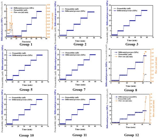
Figure 6.
Plugging curves of different groups.
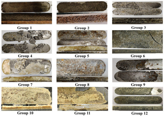
Figure 7.
Optical photos of the plugging agent and the proppant after the test.
Observation and experimental data showed a liquid outflow at the outlet end of group 1 (the average flow rate was 0.2 mL/min), and no droplet appeared after 13 min. The displacement pressure difference was continuously increased to 5, 10, 15, and 20 MPa without breakthrough, and the plugging performance was good. A large amount of liquid was released from the outlets of groups 4, 6, and 9 (the average flow rates were 22, 15, and 25 mL/min, respectively). This indicates that high-density plugging agents (densities of 1.56, 1.74, and 1.90 g/cm3) cannot achieve plugging under a 1:1 ratio. Obviously, the higher the density of the plugging agent, the more volume fraction of plugging agent is required to achieve effective plugging. However, no droplet appeared at the outlet ends of groups 8 and 13. The displacement pressure difference was continuously increased to 5, 10, and 13 MPa without breakthrough. When the displacement pressure difference of group 12 reached 15 MPa, the liquid was released from the outlet (the maximum flow rate was 15.62 mL/min). In addition, in group 8, when the displacement pressure difference reached 20 MPa, the liquid was released from the outlet (the highest flow rate was 4.19 mL/min), and the plugging performance was good. In other groups, the displacement pressure was continuously increased to 25 MPa, but no breakthrough was achieved, and the plugging efficiency reached 100%. The experimental results confirm the excellent plugging ability of the plugging agent. The optical photos of Figure 7 confirm that the plugging agent is a pale-yellow particle, distinct from the black proppant. The mixture becomes more yellow with the increase in the volume fraction of plugging agent.
3.2.2. Solubility Test
The gas solubility test is a key experiment to evaluate whether the plugging agent can automatically degrade in contact with gas. Considering the dissolution of plugging agents at different temperatures and densities over time at corresponding temperatures after curing, different sets of experiments were conducted. The experimental parameters are shown in Table 3.
Table 3.
Parameters in the gas solubility test.
The six groups of plugging agents in the above experimental program were weighed into a paper cup, and fracturing fluid was added and mixed thoroughly. They were then put in an oven and continuously heated at the corresponding experimental temperature until they were cured and taken out. The photos of the cured plugging agent are shown in Figure 8. Table 4 shows the experimental results of the dissolution capacity of the obtained plugging agent.
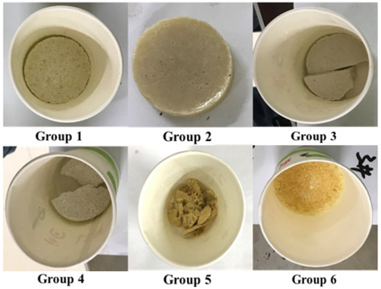
Figure 8.
Optical photographs of the plugging agent after solidification in an oven.
Table 4.
Solubility of the plugging agent.
It is clear from Table 4 and Figure 8 that the dissolution rate of the plugging agent increases over time. The solubility of the low-density (1.15 g/cm3) plugging agent reached 96.7% and 94.9% after heating for 5 h, respectively. The plugging agent in the beaker was reduced from almost full to only a little residue at the bottom of the beaker. After heating for 6 h, the solubility at 60 °C reached 97.6%, and the plugging agent in the beaker was significantly reduced again, showing good solubility. For the high-density plugging agents, the solubility was relatively low (59% to 69%) due to the addition of insoluble weighting agents. The higher the density of a plugging agent, the more insoluble material is left. Therefore, when the dissolution rate of plugging agent is calculated by mass difference method, the higher the density, the lower the dissolution rate of plugging fracturing technology controlled by plugging agent with small displacement and low displacement fracture. The optical photographs show the plugging agent residue after each hour. After 6 h, there is still a thick layer of solid at the bottom of the beaker. The dissolution of different groups of plugging agents at different times is shown in Figure 9. Generally, the plugging agent with different densities exhibited good gas solubility, with high dissolution rates achieved within a few hours.
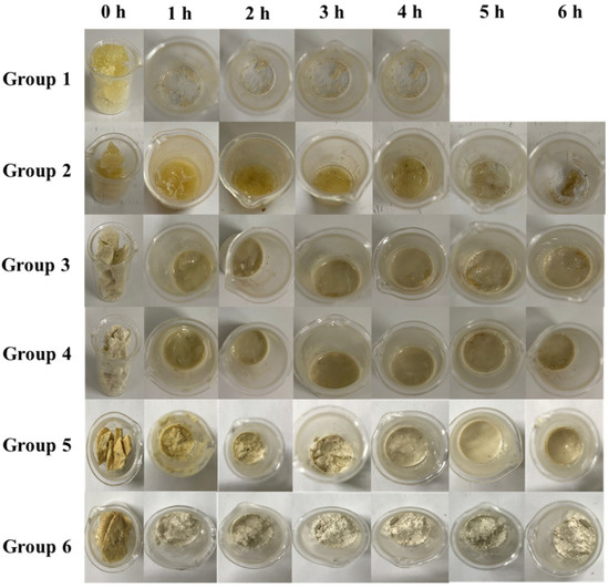
Figure 9.
Dissolution of the plugging agent at different times.
3.2.3. Settlement Rule of Plugging Agent
Using proppant sedimentation law experiments for reference, we simulated underground fractures, measured the sedimentation law and plugging performance of the water shut-off material alone and mixed with proppant in the fracturing fluid, and clarified the effect of plugging the bottom water and preventing the blockage of the gas layer.
- Rheological properties of fracturing fluid.
The fracturing fluid system was prepared according to the method in Section 2.6, and its rheological properties were tested (Figure 10).
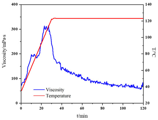
Figure 10.
High temperature rheological properties of fracturing fluid.
According to the rheological properties, the viscosity of fracturing fluid at 120 °C remains above 60 mPa·s after 120 min, which meets the requirements of fracturing (The experiment method is carried out according to Chinese oil and gas standard SY/T 5107-2016 (water-based fracturing fluid performance evaluation method)).
- Test in water.
The settlement of the plugging agent and proppant after testing the density of 1.15 g/cm3 and increasing it to 2.0 g/cm3 in clear water is shown in Figure 11 and Figure 12, and the settlement rates are shown in Table 5 and Table 6.
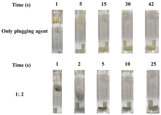
Figure 11.
Settlement of the plugging agent and proppant (density = 1.15 g/cm3) in water.
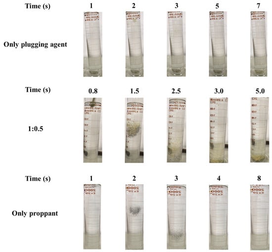
Figure 12.
Settlement of the plugging agent and proppant (density = 2.00 g/cm3) in water.
Table 5.
Sedimentation rates (cm/s) of the plugging agent and proppant (density = 1.15 g/cm3) in water.
Table 6.
Sedimentation rate (cm/s) of the plugging agent and proppant (density = 2.00 g/cm3) in water.
The results show that the settling velocity of the proppant in water is much higher than that of the plugging agent at different densities. As shown in Figure 11 and Table 5, when the plugging agent density is 1.15 g/cm3 and the volume ratio of plugging agent to proppant is 1:2, the settling velocity of the plugging agent/proppant mixture is about twice that of the pure plugging agent. The pure plugging agent was added into the clean water, and the settlement did not occur at 1 s. At 5 s, the plugging agent began to disperse and settle. At 15 s, the settlement was almost complete, and, 30 s later, the settlement was complete. However, when the 1:2 volume ratio of plugging agent and proppant was added into the water, the plugging agent and proppant settled in the first and second seconds, the proppant almost settled in the 5 s, the plugging agent almost settled in the 10 s, and settlement was completed in 25 s. Table 5 shows the sedimentation rates of the two systems after two repeated experiments. The average settlement rate of pure plugging agent is 0.69 cm/s, and that of proppant to plugging agent is 1.20 cm/s. At a proppant density of 2.00 g/cm3, similarly, the higher the proppant ratio, the faster the settling time and rate. Figure 12 and Table 6 show that the settlement rate of the plugging agent is slow, and the settlement rate is 6.67 cm/s when the plugging agent settles completely at 5.997 s. When the volume ratio of plugging agent and proppant is 1:0.5, the solid settlement rate is faster than that of pure plugging agent, and the settlement rate is 9.52 cm/s when the plugging agent settles completely at 4.201 s. The pure proppant has the highest settlement rate, with a settlement time of 3.799 s and a settlement rate of 10.53 cm/s. The results show that the presence of proppant in water is beneficial to the rapid settlement of a plugging agent.
Test in guanidine gum solution. Sedimentation at densities of 1.15 g/cm3 up to 2.0 g/cm3 was tested in a guanidine gum solution. In actual pumping, the plugging agent and proppant will disperse in the guanidine gum solution under agitation. Therefore, the influence of dispersion on sedimentation in the guanidine gum was discussed, as shown in Figure 13 and Figure 14 and Table 7 and Table 8, and the sedimentation and the sedimentation rates in the guanidine gum were given.
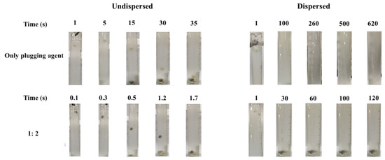
Figure 13.
Settlement of the plugging agent and proppant (density = 1.15 g/cm3) in the guanidine gum solution.
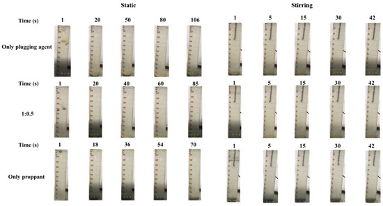
Figure 14.
Settlement of the plugging agent and proppant (density = 2.00 g/cm3) in the guanidine gum solution.
Table 7.
Sedimentation rates of the plugging agent and proppant (density = 1.15 g/cm3) in water.
Table 8.
Sedimentation rates of the plugging agent and proppant (density = 2.00 g/cm3) in water.
The experimental test results in Figure 13 show that, when the density is 1.15 g/cm3, the plugging agent and proppant in guanidine gum solution completely settle and bond together, making it difficult to separate without dispersing. With the increased volume ratio of proppant, the settling velocity of the plugging agent increases significantly. Table 7 shows that, when the ratio is 1:2, the settling velocity of the plugging agent is about 21 times that of pure plugging agent. The settling time of the pure plugging agent is 35.8 s and the settlement rate is 0.84. When the volume ratio of the propped collector is 1:2, the settling time is reduced to 1.7 s and the settlement rate is 17.65 cm/s. However, in the actual pumping, there is a stirring effect, and the plugging agent and proppant will disperse in guanidine gum base liquid. Therefore, the dispersion settlement experiment is carried out and the plugging agent and proppant are dispersed into guanidine gum artificially, and the settlement process is observed. Figure 14 shows a dispersion settlement experiment where the plugging agent and proppant settle together. With the increased volume ratio of the proppant, the settling velocity of the plugging agent increases significantly. When the ratio is 1:2, the settling velocity of the plugging agent is about six times that of the pure plugging agent. Table 7 shows that the presence of the proppant facilitates rapid settlement of the plugging agent. The settling time of the pure plugging agent is 684 s and the settlement rate is 0.04 cm/s. When the volume ratio is 1:2, the settlement time is reduced to 120 s and the settlement rate is 0.25 cm/s. At a density of 2.00 g/cm3, Figure 15 shows that, as the proppant ratio increases, the faster the settling time increases, the faster the settlement rate increases. Again, the presence of the proppant is conducive to rapid settlement of the plugging agent. Table 8 shows that, when the settling time of the pure plugging agent, the volume ratio of the plugging agent and proppant is 1:0.5, the pure proppant in guanidine gum solution is 106 s, 85 s, and 70 s, respectively, and the corresponding settlement rates are 0.38 cm/s, 0.47 cm/s, and 0.57 cm/s, respectively. In addition, it is proved that stirring can reduce the settling velocity. In the stirring experiment in Figure 14, the overall settlement rate slows down. In Table 8, when the settlement time of the volume ratio of pure plugging agent, plugging agent, and proppant is 1:0.5, pure proppant in guanidine gum solution is 180 s, 145 s, and 117 s, respectively, and the corresponding settlement rate is 0.22 cm/s, 0.28 cm/s, and 0.34 cm/s, respectively.
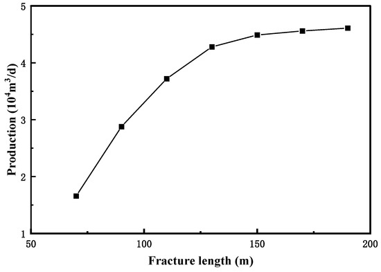
Figure 15.
Production curve after fracturing at different fracture lengths.
3.3. Field Test and Post-Fracturing Evaluation
The preliminary field tests of water plugging and fracturing were conducted in a typical gas well with bottom water, and the post-fracturing effects were evaluated and analyzed. Then, improvement measures were put forward to provide bases for further experiments.
3.3.1. Basic Information on the Reservoir and Well
A typical bottom water gas well (J66-8-3) in Shanxi Formation was selected to perform a preliminary field test of water plugging and fracturing. The well was drilled to a depth of 2611.85 m. The well was completed with a 41/2″ casing and perforated at 2570–2572 m and 2574–2576 m. The formation closure pressure gradient was about 0.0158 MPa/m, and the formation closure pressure was 40.3 MPa. Other specific data for well J66-8-3 are shown in Table 9.
Table 9.
Data for well J66-8-3.
3.3.2. Treatment Design
The following treatment processes and parameters were designed to ensure a suitable fracturing and water shut-off process:
- (1)
- Through logging interpretation, it is found that the gas layer He 13 (2558.8–2576.6 m) of well J66-8-3 is adjacent to the lower gas and water layer (2579.2–2598.0 m). The well layer was suitable for the sealing bottom water fracturing technology. As the distance between He 21 and He 13 was relatively long and the intermediate layer was better, the sealing method was used for fracturing separately. Therefore, He 21 was not considered during water plugging and fracturing.
- (2)
- Because of the large amount of water produced by well J66-8-3 in the early stage, fracturing was often performed by controlling the scale and displacement, resulting in relatively short fracture lengths (118 m) in the early-stage fracturing wells and insufficient reservoirs. The main idea of blocking bottom water fracturing involves uncontrollable scales, uncontrollable fracture heights, and long fractures. Therefore, the length of the fracture must be optimized from a full transformation perspective, and the amount of water plugging material must be optimized according to the expansion of the height of the fracture.
- (3)
- Another parameter is the selection of the temperature of the water-blocking material. According to the geothermal gradient of the block and the vertical depth of the well, the temperature of the target layer was calculated to be 67 °C. According to the research results of the project, a water shut-off material with a temperature of 60 °C can be selected.
- (4)
- The density of the water-blocking material was then selected. According to the average pressure coefficient of the target layer (0.83), the formation pressure of the target layer must be lower than 20.8 MPa. Because of the large thickness of the gas and water layer in this well, from a cost-saving perspective, a water shut-off method combining a water shut-off material and a proppant should be considered. At the same time, high-density water shut-off materials should be used to reduce the shut-in time of the pump. In consideration of the plugging experiment of the water shut-off material, using a 1.9 g/cm3 water shut-off material is recommended, and the water shutoff should be based on a 1:0.5 volume ratio of the water shutting material and proppant. The production pressure difference should not be greater than 15 MPa. We also used the sinking time to determine the experiment and put forward reasonable suggestions.
- Fracture length optimization.
The fracture length was optimized with production as the goal to fully transform the reservoir. The basic parameters used for calculation were as follows: reservoir thickness, 15 m; porosity, 15%; permeability, 2.5 mD; gas saturation, 38%; and diversion capacity, 20 D∙cm. Figure 15 shows the relationship between the fracture length and the output after pressing. Production first increases with the increase in seam length. When the fracture length reaches about 150 m, production hardly increases and the curve appears to plateau. Finding a 150 m fracture length was advisable, so a 150 m fracture length was taken as the target layer.
- Optimization of the plugging agent dosage.
According to the simulation, the hydraulic fractures in the well entered the water layer 13.7 m after water plugging and fracturing. According to the calculation using the fracture half-length of 150 m, the well should pump 10.8 m3 of the plugging agent and proppant mixture during the pre-fluid-plugging stage (where the plugging agent composes 7.2 m3 of the total volume, whereas the proppant composes 3.6 m3). We calculated the amount of plugging agent and proppant (1:0.5 volume ratio of the plugging agent to the proppant) required to plug the gas and water layers of the well under different fracture lengths, and the results are shown in Figure 16. As the required length increases, the amount of proppant and plugging agent increase. When the length is about 80 m, 3.8 m3 of plugging agent and 1.9 m3 of proppant are required. At 160 m, 7.7 m3 plugging agent and 3.9 m3 proppant were required. The longer the fracture, the more proppant and plugging agents are needed to create the fracture and plug the water.
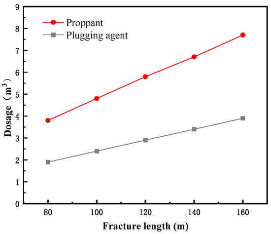
Figure 16.
Plugging agent and proppant dosages for different fracture lengths.
- Determination of sinking time.
According to the basic characteristics of the well layers of J66-8-3, the fracture morphology after water plugging and fracturing was simulated (Figure 17). The length of the support fracture was 151.5 m (13.7 m into the water layer), and the height of the support fracture was 40.6 m (2552.3–2592.9 m).
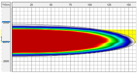
Figure 17.
Fracture morphology after fracturing.
According to the research results, the sinking timing should be calculated according to the fracture height and the settlement speed of the plugging agent. When the volume ratio of the plugging agent to the proppant was 1:0.5, the settlement time of the plugging agent with a density of 1.9 g/cm3 in the gel breaker was calculated as shown in Figure 18. It was found that the settling time of the plugging agent and proppant mixture increased linearly as the height of the fracture increased. The settling time of the plugging agent was 2.8 h in the case of a fracture height of 40.6 m. After the well pump was injected with the plugging agent, the settling time of the plugging agent was 2.8 h. We recommend stopping the pump for 3.0 h to allow the plugging agent to fully settle.
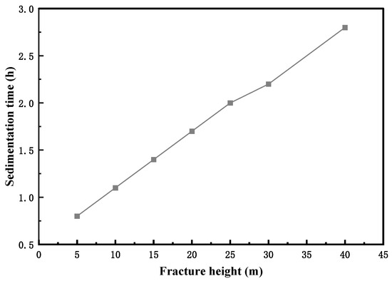
Figure 18.
Settlement time at different fracture heights.
The water plugging and fracturing construction procedures for well J66-8-3 were adjusted considering the requirements of block reconstruction and the above water plugging and fracturing optimization results, and the results are shown in Table 10.
Table 10.
Fracturing treatment pump injection procedure.
3.3.3. Evaluation Methods for the Post-Fracturing Wells
- Fracture height assessment.
The propagation of the fracture height after water plugging and fracturing can be obtained through temperature logging and net pressure fitting, and the relationship between the fracture height obtained and the gas–water layer interpreted by logging was determined to distinguish situations where the fracture height enters the water layer.
- (1)
- If the fracture height extends but does not enter the lower water layer, it indicates that the scale of water plugging fracturing is small or the isolation layer condition is good (i.e., the water plugging fracturing technology is unnecessary).
- (2)
- If the fracture height extends into the lower water layer, the bottom of the fracture height and the position of the water layer are further compared to obtain the depth of the fracture height into the water layer, which is compared with the water plugging fracturing design to determine whether the amount of the designed plugging agent is enough to block the water layer.
- Production analysis.
Water production is the direct display of the water plugging effect, and gas production is the ultimate goal of water plugging fracturing. Therefore, evaluating the effect of water plugging and fracturing from the aspects of water production and gas production is necessary. This can be conducted by comparing local wells and adjacent wells.
- (1)
- Comparison in a local well. If a well is produced before fracturing, we can directly compare its daily water and gas production before and after plugging and fracturing under the same production system. We can then calculate the increase in gas production and decrease in water production of the well to quantify the effect of plugging and fracturing.
- (2)
- Comparison of adjacent wells. Adjacent wells with similar formation conditions and without water plugging and fracturing technology were compared with the example well. Under the same production system, we compared the daily gas production and daily water production of the adjacent wells and the example well. Then, we calculated the increase in the daily gas production of the example well and the decrease in the daily water production compared with that of the adjacent wells.
The rationality of a water plugging fracturing design and the effectiveness of water plugging fracturing can be effectively evaluated by evaluating the fracture height and analyzing the production situation. On this basis, improvement measures are put forward to constantly improve the water plugging fracturing technology and improve the pertinence and effectiveness of the water plugging fracturing technology.
4. Conclusions
This study includes laboratory study and field applications of a plugging agent, and the experimental results obtained led us to the following conclusions:
- (1)
- Using pyrophosphoryl chloride, p-hydroxybenzaldehyde, and lactide as raw materials, a polylactide polymer plugging agent was successfully synthesized by a multi-step method.
- (2)
- The plugging agent has excellent plugging performance. When the ratio of plugging agent to proppant is 1:1 and 1:2, the plugging rate of 1.15 g/cm3 water plugging material can achieve 100%. The plugging rate of 1.56 g/cm3 and 1.74 g/cm3 density plugging materials is 100% at 1:0.5, and the plugging rate of 1.90 g/cm3 and 2.0 g/cm3 density plugging materials is 100% at 1:0.5.
- (3)
- The solubility of the low-density (1.15 g/cm3) plugging agent reached 96.7% and 94.9% after heating for 4 h, and 97.6% after heating for 6 h, showing excellent solubility. For high-density plugging agents, the solubility is relatively low (59 to 69%) due to the addition of insoluble weighting agents.
- (4)
- The settlement rate of a pure plugging agent in water and guar solution is slower than that of a proppant. As the proppant volume ratio increases, the sedimentation rate increases. In general, the presence of a proppant accelerates the settlement of a plugging agent.
- (5)
- According to the actual well conditions of J66-8-3, the fracture length, plugging agent addition, and plugging agent sinking time were optimized and the single-well fracturing scheme was improved, providing reference for the realization of bottom water plugging fracturing technology in similar wells.
Author Contributions
Conceptualization, A.H.; methodology, A.H. and K.L.; software, H.F.; validation, H.F. and Y.Z.; formal analysis, Y.F.; investigation, Y.Z.; resources, A.H.; data curation, Y.F.; writing—original draft preparation, A.H.; writing—review and editing, Y.F. and Y.Z.; visualization, K.L.; supervision, H.F.; project administration, Y.F.; funding acquisition, Y.Z. All authors have read and agreed to the published version of the manuscript.
Funding
This research was funded by State Key Laboratory of Oil and Gas Reservoir Geology and Exploitation (Chengdu University of Technology), grant number PLC20210306.
Institutional Review Board Statement
Not applicable.
Informed Consent Statement
Not applicable.
Data Availability Statement
Not applicable.
Conflicts of Interest
The authors declare no conflict of interest.
References
- Wang, H.; Ma, F.; Tong, X.; Liu, Z.; Zhang, X.; Wu, Z.; Li, D.; Wang, B.; Xie, Y.; Yang, L. Assessment of global unconventional oil and gas resources. Pet. Explor. Dev. 2016, 43, 925–940. [Google Scholar] [CrossRef]
- Pang, X.Q.; Jia, C.Z.; Wang, W.Y.; Chen, Z.X.; Li, M.W.; Jiang, F.J.; Hu, T.; Wang, K.; Wang, Y.X. Buoyance-driven hydrocarbon accumulation depth and its implication for unconventional resource prediction. Geosci. Front. 2021, 12, 101133. [Google Scholar] [CrossRef]
- Tang, X.; Zhang, J.; Shan, Y.; Xiong, J. Upper Paleozoic coal measures and unconventional natural gas systems of the Ordos Basin, China. Geosci. Front. 2012, 3, 863–873. [Google Scholar] [CrossRef]
- King, G.E.; Durham, D. Environmental aspects of hydraulic fracturing: What are the facts? In Hydraulic Fracturing: Environmental Issues; American Chemical Society: Washington, DC, USA, 2015; Volume 1216, pp. 1–44. [Google Scholar]
- Osborn, S.G.; Vengosh, A.; Warner, N.R.; Jackson, R.B. Methane contamination of drinking water accompanying gas-well drilling and hydraulic fracturing. Proc. Natl. Acad. Sci. USA 2011, 108, 8172–8176. [Google Scholar] [CrossRef]
- Shaffer, D.L.; Chavez, L.H.A.; Ben-Sasson, M.; Castrillon, S.R.V.; Yip, N.Y.; Elimelech, M. Desalination and Reuse of High-Salinity Shale Gas Produced Water: Drivers, Technologies, and Future Directions. Environ. Sci. Technol. 2013, 47, 9569–9583. [Google Scholar] [CrossRef]
- Arthur, M.A.; Cole, D.R. Unconventional Hydrocarbon Resources: Prospects and Problems. Elements 2014, 10, 257–264. [Google Scholar] [CrossRef]
- Song, Y.; Li, Z.; Jiang, L.; Hong, F. The concept and the accumulation characteristics of unconventional hydrocarbon resources. Pet. Sci. 2015, 12, 563–572. [Google Scholar] [CrossRef]
- Xie, Z.; Yang, C.; Li, J.; Zhang, L.; Guo, J.; Jin, H.; Hao, C. Accumulation characteristics and large-medium gas reservoir-forming mechanism of tight sandstone gas reservoir in Sichuan Basin, China: Case study of the Upper Triassic Xujiahe Formation gas reservoir. J. Nat. Gas Geosci. 2021, 6, 269–278. [Google Scholar] [CrossRef]
- Qin, Y.; Yao, S.; Xiao, H.; Cao, J.; Hu, W.; Sun, L.; Tao, K.; Liu, X. Pore structure and connectivity of tight sandstone reservoirs in petroleum basins: A review and application of new methodologies to the Late Triassic Ordos Basin, China. Mar. Pet. Geol. 2021, 129, 105084. [Google Scholar] [CrossRef]
- Zhong, Y.; Zhang, H.; Kuru, E.; Kuang, J.; She, J. Mechanisms of how surfactants mitigate formation damage due to aqueous phase trapping in tight gas sandstone formations. Colloids Surf. A Physicochem. Eng. Asp. 2019, 573, 179–187. [Google Scholar] [CrossRef]
- Huang, L.; Dontsov, E.; Fu, H.; Lei, Y.; Weng, D.; Zhang, F. Hydraulic fracture height growth in layered rocks: Perspective from DEM simulation of different propagation regimes. Int. J. Solids Struct. 2022, 238, 111395. [Google Scholar] [CrossRef]
- Fu, S.; Hou, B.; Xia, Y.; Chen, M.; Wang, S.; Tan, P. The study of hydraulic fracture height growth in coal measure shale strata with complex geologic characteristics. J. Pet. Sci. Eng. 2022, 211, 110164. [Google Scholar] [CrossRef]
- Pandey, V.J.; Rasouli, V. A semi-analytical model for estimation of hydraulic fracture height growth calibrated with field data. J. Pet. Sci. Eng. 2021, 202, 108503. [Google Scholar] [CrossRef]
- Zhang, Y.; Yu, R.; Yang, W.; Tian, Y.; Shi, Z.; Sheng, C.; Song, Y.; Du, H. Effect of temporary plugging agent concentration and fracturing fluid infiltration on initiation and propagation of hydraulic fractures in analogue tight sandstones. J. Pet. Sci. Eng. 2022, 210, 110060. [Google Scholar] [CrossRef]
- Wang, T.; Chen, M.; Wu, J.; Lu, J.; Luo, C.; Chang, Z. Making complex fractures by re-fracturing with different plugging types in large stress difference reservoirs. J. Pet. Sci. Eng. 2021, 201, 108413. [Google Scholar] [CrossRef]
- Wang, D.; Dong, Y.; Sun, D.; Yu, B. A three-dimensional numerical study of hydraulic fracturing with degradable diverting materials via CZM-based FEM. Eng. Fract. Mech. 2020, 237, 107251. [Google Scholar] [CrossRef]
- Xu, L. In Study on the shut-off mechanism of volumetric swell agent and productivity simulation for bottom water reservoir. In Proceedings of the 2016 International Conference on Progress in Informatics and Computing (PIC), Shanghai, China, 23–25 December 2016; pp. 449–454. [Google Scholar]
- Li, L.; Wu, Y.; Guo, N.; Zhou, J.; Liu, T.; Zhang, Z.; Li, Y.; Cai, G. Application of selective water plugging technology for slotted pipe horizontal well. IOP Conf. Ser. Earth Environ. Sci. 2019, 252, 052109. [Google Scholar] [CrossRef]
- Zhang, L.; Xiong, Y.M.; Xu, J.N.; Cheng, Y.; Liu, L.M.; Shan, Y.K. Delaying bottom water coming intelligent well completion technology research. In Proceedings of the Asia-Pacific Power and Energy Engineering Conference (APPEEC), Chengdu, China, 28–31 March 2010. [Google Scholar]
- Zhao, J.S.; Li, T.T.; Shi, Y.; An, C.Q.; Liu, Y.L. A new sinking agent used in water-control fracturing for low-permeability/bottom-water reservoirs: Experimental study and field application. J. Pet. Sci. Eng. 2019, 177, 215–223. [Google Scholar] [CrossRef]
- Qi, N.; Li, B.; Chen, G.; Liang, C.; Ren, X.; Gao, M. Heat-Generating Expandable Foamed Gel Used for Water Plugging in Low-Temperature Oil Reservoirs. Energy Fuels 2018, 32, 1126–1131. [Google Scholar] [CrossRef]
- Liu, J.; Zhang, Y.; Li, X.; Dai, L.; Li, H.; Xue, B.; He, X.; Cao, W.; Lu, X. Experimental Study on Injection and Plugging Effect of Core–Shell Polymer Microspheres: Take Bohai Oil Reservoir as an Example. ACS Omega 2020, 5, 32112–32122. [Google Scholar] [CrossRef]
- Li, J.; Niu, L.; Lu, X. Migration characteristics and deep profile control mechanism of polymer microspheres in porous media. Energy Sci. Eng. 2019, 7, 2026–2045. [Google Scholar] [CrossRef]
- Guo, Y.; Pu, W.; Zhao, J.; Guo, Y.; Lian, P.; Liu, Y.; Wang, L.; Yu, Y. Effect of the foam of sodium dodecyl sulfate on the methane hydrate formation induction time. Int. J. Hydrog. Energy 2017, 42, 20473–20479. [Google Scholar] [CrossRef]
- Zhang, Y.; Cai, H.; Li, J.; Cheng, R.; Wang, M.; Bai, X.; Liu, Y.; Sun, Y.; Dai, C. Experimental study of acrylamide monomer polymer gel for water plugging in low temperature and high salinity reservoir. Energy Sources Part A Recovery Util. Environ. Eff. 2018, 40, 2948–2959. [Google Scholar] [CrossRef]
- Liu, E.H. Research and application of high temperature gel plugging agent. Appl. Mech. Mater. 2014, 675–677, 1565–1568. [Google Scholar] [CrossRef]
- Xie, K.; Su, C.; Liu, C.; Cao, W.; He, X.; Ding, H.; Mei, J.; Yan, K.; Cheng, Q.; Lu, X. Synthesis and Performance Evaluation of an Organic/Inorganic Composite Gel Plugging System for Offshore Oilfields. ACS Omega 2022, 7, 12870–12878. [Google Scholar] [CrossRef]
- Zhang, X.; Liu, W.; Yang, L.; Zhou, X.; Yang, P. Experimental Study on Water Shutoff Technology Using In-Situ Ion Precipitation for Gas Reservoirs. Energies 2019, 12, 3881. [Google Scholar] [CrossRef]
- Gao, Y.; Chen, S.; Huang, F.; Gao, Y.; Song, T.; Wang, S.; Jia, P.; Liu, C. Micro-occurrence of formation water in tight sandstone gas reservoirs of low hydrocarbon generating intensity: Case study of northern Tianhuan Depression in the Ordos Basin, NW China. J. Nat. Gas Geosci. 2021, 6, 215–229. [Google Scholar] [CrossRef]
- Zhao, X.; Zhu, S. Prediction of water breakthrough time for oil wells in low-permeability bottom water reservoirs with barrier. Pet. Explor. Dev. 2012, 39, 504–507. [Google Scholar] [CrossRef]
- He, Y.; Qin, J.; Cheng, S.; Chen, J. Estimation of fracture production and water breakthrough locations of multi-stage fractured horizontal wells combining pressure-transient analysis and electrical resistance tomography. J. Pet. Sci. Eng. 2020, 194, 107479. [Google Scholar] [CrossRef]
- Zhang, Y.; Zhang, D.; Wen, Q.; Zhang, W.; Zheng, S. Development and evaluation of a novel fracture diverting agent for high temperature reservoirs. J. Nat. Gas Sci. Eng. 2021, 93, 104074. [Google Scholar] [CrossRef]
Publisher’s Note: MDPI stays neutral with regard to jurisdictional claims in published maps and institutional affiliations. |
© 2022 by the authors. Licensee MDPI, Basel, Switzerland. This article is an open access article distributed under the terms and conditions of the Creative Commons Attribution (CC BY) license (https://creativecommons.org/licenses/by/4.0/).