Article

Research and Design of LC Series Resonant Wireless Power Transfer System with Modulation Control Method for Supercapacitor Charging in Linear Motion Systems

1
College of Automation, Jiangsu University of Science and Technology, Zhenjiang 212000, China
2
Department of Electrical Engineering, Yangzhou University, Yangzhou 225012, China
3
Haitong Electronic Technology Co., Yangzhou 225100, China
*
Author to whom correspondence should be addressed.
Energies 2022, 15(18), 6739; https://doi.org/10.3390/en15186739
Submission received: 24 August 2022 / Revised: 11 September 2022 / Accepted: 12 September 2022 / Published: 15 September 2022

Abstract

:
With the hot topic of “Carbon Neutrality”, energy efficiency and saving practices such as reducing fuel consumption, vigorously advocating new energy power and modern rail are now becoming the main research topics of energy conversion technologies. Supercapacitors, with their ability of higher power density, fast charging, and instantaneous high current output, have become an indispensable energy storage element in modern traction systems for modern rail. This proposal introduced wireless power transfer technologies by using LC series resonant technology for charging the supercapacitors. To match the voltage and current level of the supercapacitor, a four-switch buck-boost converter was applied on the secondary side of the load-matching converter. To regulate the wireless transfer power and charging power of the supercapacitor, the active modulation control method was introduced on both the primary and secondary sides of the transfer system. On the primary side, the power is controlled by controlling the current in resonant inductance through the phase shift control method, while on the secondary side, the charging power is controlled by regulating the input voltage of the four-switch buck-boost converter followed by inductance current control. The theoretical analysis under phase shift mode for the primary side and pulse width modulation for a four-switch buck-boost converter with a supercapacitor load (voltage source) were proposed in detail, and the state-space model of the load matching converter was established for controller design to obtain precise voltage and current control. Both open loop and closed loop simulation models were built in the MATLAB/SIMULINK environment, and simulations were carried out to evaluate the system characteristics and control efficiency. The experimental platform was established based on a dsPIC33FJ64GS606 digital controller. Experiments were carried out, and the results successfully verified the effectiveness of the system.

1. Introduction

Compared with traditional rail, modern rail has been introduced in many cities with the advantages of energy storage, strong adaptability, flexibility, and convenience. Energy storage equipment determines the endurance mileage of modern rail [1,2]. As the most widely used energy storage equipment, battery strings are usually heavy and bulky [3]. To reduce these disadvantages and increase the power receiving ability, using a supercapacitor can be a considerable solution [4]. As the most mature technology of power supply, supplying power by catenary is widely used in modern trams. However, some shortcomings such as contact spark, and wear exist in this power supply mode. To address these issues, the emerging wireless power transfer (WPT) is particularly attractive for modern rail [5,6,7].
A supercapacitor is widely used as a high-power density energy storage device with the advantages of high current, fast charging and discharging [8], long cycle life [9], high power density [10], high efficiency [11], and environmental protection [12], so the supercapacitors show strong adaptability to the market [13,14]. Supercapacitors have been used as energy storage devices in many high-power applications, such as DC microgrids [15,16] and light rail [17,18]. Supercapacitors perform better than traditional batteries in the field of energy vehicles [19]. Many investigations of supercapacitors have been performed. The different charging strategies for standalone supercapacitors, lithium-ion (Li-ion), and lead-acid batteries were evaluated [20]. The charge redistribution behavior of supercapacitors was analyzed by constant power discharge experiments [21]. A simplified circuit model for supercapacitors based on the voltage-current equation was proposed [22]. In short, although supercapacitors still face some challenges [23], they can be greatly improved in the future [24,25].
For a wireless power transfer (WPT) system applied in modern rail, efficiency and power are two significant factors [26,27]. To increase the efficiency of the system, improving the compensation circuit can achieve optimal control of the equivalent load [28]. To satisfy the requirements of output voltage and current, topology and control strategies are proposed to achieve constant current and voltage [29].
This paper introduces WPT technology into a supercapacitor charging system and proposes an LC resonant WPT system with a modulation control method for supercapacitor charging. An LC series resonant coupling network is applied for power transfer, and a four-switch buck-boost converter is introduced to match the voltage level of the supercapacitor while charging and controlling the charging power. The transfer power is adjusted through both the primary coil RMS current control method and the secondary side voltage-current double-loop control method. The rest of this manuscript is arranged as follows: The structure and topology of the proposed system are introduced in detail in Section 2. Section 3 provides the control system design for primary coil RMS current control and secondary voltage-current control. The simulation and experimental results are presented in Section 4 and Section 5, respectively. The results are compared between simulations and experiments to verify the system characteristics and evaluate the control efficiency. Finally, brief conclusions are made in Section 6.

2. Configuration of the Proposed WPT Charging System

Figure 1 shows the system structure of the proposed wireless power charging system, which mainly consists of six main parts: a DC grid (power source), a high-frequency DC/AC inverter, a resonant coupling tank, a full-bridge AC/DC rectifier, a DC/DC power regulator unit, and supercapacitor (system load). The detailed system topology is presented in Figure 2.
As shown in Figure 2, the system can be divided into a primary side and secondary side. On the primary side, the DC grid is simulated by a DC voltage source as the input power of the system, and a full bridge inverter driven by high-frequency PWM transforms the DC voltage to high-frequency AC to supply the LC series resonant coupling tank for power transfer. On the secondary side, the same LC series resonant tank is applied to receive the power transferred from the primary side, and a full bridge rectifier is introduced to convert the received AC voltage to DC voltage. To match the voltage level and control the charging power of the supercapacitor, a DC/DC converter in the form of a four-switch buck-boost converter is applied as a load-matching converter. In this topology, M represents the mutual inductance between the primary and secondary coils. The primary and secondary coil inductances are represented by Lp and Ls, respectively. The resonant capacitors of the primary and secondary coils are expressed by Cp and Cs, respectively.
In this proposal, the modulation control method has been introduced on both the primary side and secondary side. The phase shift control method is applied on the primary side to control the RMS value of the current in Lp, while on the secondary side, the four-switch buck-boost input voltage and inductance current controls are used to control the transfer power.

2.1. Coupling Tank Analysis

For wireless power transfer, the power is transferred from the primary side to the secondary side through inductance coupling, thus the coupling tank plays a significant role in the proposed system. Figure 3 presents the T-type equivalent circuit of the LC resonant coupling tank, where Lp and Cp indicate the primary resonant inductance and capacitor, respectively. Ls and Cs indicate the secondary resonant inductance and capacitor, respectively. Up is the voltage on the resonant tank, Us is the output voltage on load RL, and Ip and Is represent the input current and output current, respectively. M is the magnetic inductance between the primary coil and the secondary coil.
Due to the system working under a resonant state, the energy transfer efficiency (η) can be calculated as Equation (1), where ωr is the angular speed of the current.
η = I s 2 R L I p 2 R p + I s 2 R s + I s 2 R L = R L ( R L + R s ) ( 1 + R p ( R s + R L ) ω r 2 M 2 )
The relationship between Ip and Is is determined by the switching frequency, which should satisfy Equation (2), then Ip and Is will have the relationship shown in Equation (3).
f > R p ( R L + R s ) M 2
I p I s = R s + R L ω 0 M
Due to the small internal resistance of the primary coil and secondary coil, the maximum energy transfer efficiency (ηmax) can be approximated as Equation (4).
η max = R L R s + R L
We can conclude that the maximum transfer efficiency is almost 1 and cannot be easily affected by the load RL.

2.2. Coil Current Constant Characteristics

The proposed WPT system uses a series resonant coupling structure for power transfer, and the current in the coils may have constant characteristics when controlling the input voltage of the four-switch buck-boost conversion constant. The equivalent circuit with a full bridge rectifier and controlled voltage Vin is shown in Figure 4. Lp and Cp indicate the primary resonant inductance and capacitor, respectively. Ls and Cs indicate the secondary resonant inductance and capacitor, respectively. up(t) is the voltage on the resonant tank, us(t) is the input voltage of the rectifier, and ip(t), is(t) represent the input current and output current, respectively. M is the magnetic inductance between the primary coil and the secondary coil. RL represents the equivalent load.
Assuming that the coefficiency between Lp and Ls is k, the DC input voltage is E, the system frequency equals the resonant frequency ω0, the resonant frequency can be obtained as the equation: ω 0 = 2 π L p L s . The magnetic inductance between the primary coil and secondary coil can be expressed as Equation (5). K is the coupling factor in the equation.
M = K L p L s
According to the calculation principle of the full-bridge inverter and rectifier, the voltages up(t) and us(t) can be obtained as Equations (6) and (7), respectively.
u p ( t ) = 4 E π sin ( ω 0 t )
u s ( t ) = 4 V i n π sin ( ω 0 t + π 2 )
Additionally, the voltage can be calculated by Kirchhoff’s law, as Equations (8) and (9).
i p ( t ) ( j ω 0 L p + 1 j ω 0 C p + R p ) j ω 0 M i s ( t ) = u p ( t )
i 2 ( t ) ( j ω 0 L 2 + 1 j ω 0 C 2 + R 2 ) j ω 0 M i 1 ( t ) = u 2 ( t )
Due to the system working under a resonant state, the inductor resistance Rp and Rs can be ignored; thus, based on the resonant theory, Equation (10) can be obtained.
j ω 0 L p + 1 j ω 0 C p = j ω 0 L s + 1 j ω 0 C s = 0
Substituting Equation (10) into Equations (8) and (9), Equations (11) and (12) can be expressed.
j ω 0 M i s ( t ) = u p ( t )
j ω 0 M i p ( t ) = 4 V i n π sin ( ω 0 t + π 2 )
By simplifying the above equations, the time domain current in the primary coil and secondary coil can be concluded as Equations (13) and (14), respectively.
i s ( t ) = u p ( t ) j ω 0 M
i p ( t ) = 4 V i n π j ω 0 M sin ( ω 0 t + π 2 )
From the above analysis, it can be concluded that: (1) the primary coil current is only influenced by the controlled input voltage of the four-switch buck-boost converter Vin; once Vin is controlled, the current will be determined; (2) the secondary coil current is only determined by the input voltage of the inverter (power supply voltage), independent of the load.

3. Control System Design

The control strategies of the proposed system can be divided into two parts: (a) primary coil RMS current control; and (b) secondary power adjustment control. The primary coil RMS current control uses a phase-shift control method to limit the maximum transfer power of the coupling tank, while the secondary power adjustment control applies four-switch buck-boost input voltage control followed by an inductance current control loop to regulate the charging power of the supercapacitor.

3.1. Primary Coil RMS Current Control

On the primary side, the switching frequency of the inverter is set to be the resonant frequency; thus, to limit the maximum transfer power and the power capability of the primary side, the primary coil RMS current control through the phase-shift method needs to be applied. The diagram of the primary coil RMS current control is shown in Figure 5, where a conventional PI controller is applied to control the coil current by adjusting the phase angle θ of the inverter driving signal.
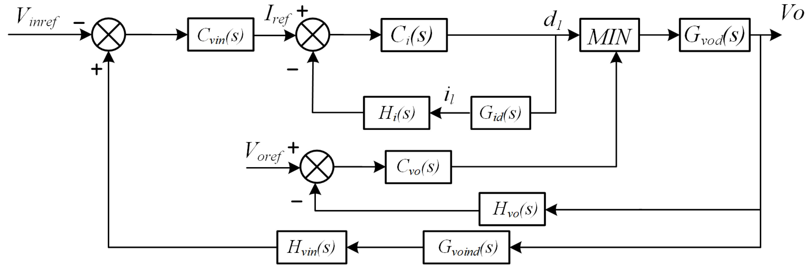
Ci1(s) is the conventional PI controller, which generates the phase shift angle for the PWM generator to drive the power stage full-bridge inverter, and H(s) is the feedback current transfer function, which is combined by the RMS current sensor with a low pass filter.

3.2. Secondary Side Power Regulation Control

In this system, a four-switch buck-boost is proposed for dedicated and real-time management of the supercapacitor due to the voltage and current undergoing swings during the charging process. For instance, if a supercapacitor is out of power, its voltage is zero, and then the charging current should be the maximum limit to ensure quick charging. During the charging process, the voltage of the supercapacitor rises, and the current should be minimized to guarantee the trickle charging stage.
The block diagram of secondary power regulation control is presented in Figure 6, and a double loop with an overcharging protection control diagram is proposed. The voltage control loop is an outer loop that is applied to control the input voltage of the four-switch buck-boost load matching converter and generate the inductance current reference value for the inner current loop. The protection loop prevents the supercapacitor from overcharging.
From the above diagram, Cvin(s) is the voltage loop controller, while Ci(s) is the inner current loop controller. Both controllers are conventional PI controllers, formed as Equation (16).
C ( s ) = K p + K i s
Cvo(s) is the overcharge protection controller, which will work only when the voltage of the supercapacitor is higher than reference Voref, then the duty of PWM will be limited by d2, otherwise, the PWM duty is controlled by d1. Gvod(s) is the transfer function between the output voltage of the four-switch buck-boost converter and PWM duty, while Gvind(s) indicates the relationship between the output voltage and input voltage of the converter, and Gid(s) represents the transfer function between the inductance current and PWM duty. Through the small-signal modeling method, the transfer functions can be obtained as Equations (16)–(18), respectively.
G v o d ( s ) = u ˜ o u t ( s ) d ˜ ( s ) = U i n L · I L · s L · C · s 2 + L R · s + ( 1 D ) 2
G i d ( s ) = i ˜ L ( s ) d ˜ ( s ) = C U i n 1 D s + 1 R ( 1 D ) U i n + ( 1 D ) I L L C s 2 + L R s ( 1 D ) 2
G v o i n d ( s ) = G v i n d ( s ) G v o u t d ( s ) = u ˜ i n ( s ) d ˜ ( s ) u ˜ o u t ( s ) d ˜ ( s ) = I L · L · s U i n D D 2 · L · C · s 2 + L R · s + ( 1 D ) 2 U in L · I L · s

4. System Simulation Results

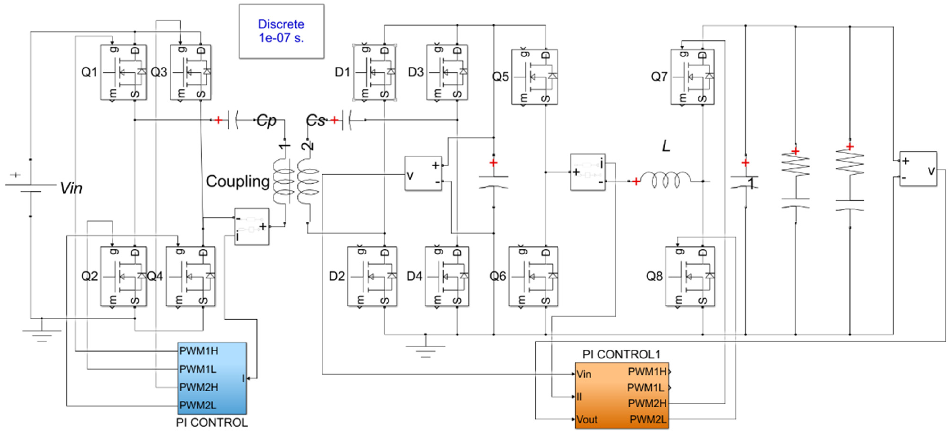
To verify with theoretical analysis of the designed WTP charging system, the simulation model was built up in the MATLAB/SIMULINK environment. The system simulations included two phases. Phase 1 was an open-loop system characteristics scan simulation. Phase 2 was closed-loop simulation to verify the effectiveness of the control system. The simulation model is shown in Figure 7, and Table 1 presents the simulation parameters.

4.1. Open-Loop System Simulation Results

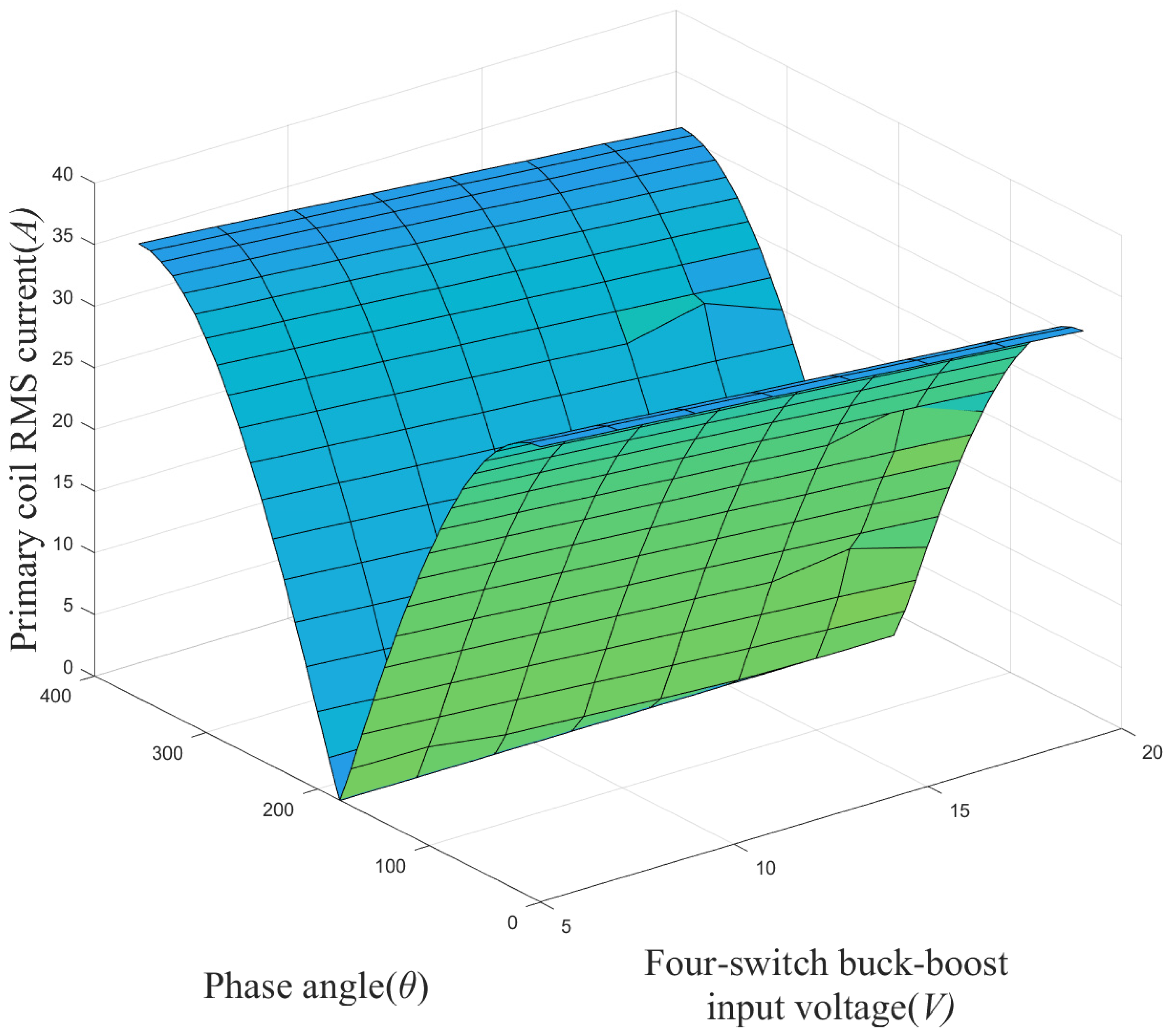
Open-loop stimulation was focused on the relationship between the primary coil RMS current and phase angle of inverter driving signals, also with a constant four-switch buck-boost input voltage scan. The simulation results are shown in Figure 8.
From the simulation results, it can be concluded that the RMS current in the primary coil decreases while the phase angle increases from 0 to 180 degrees, and in direct proportion to the phase angle θ from 180 to 360 degrees.
In addition, the input voltage of the four-switch buck-boost converter has a weak inverse influence on the RMS current.

4.2. Closed-Loop Simulation Results

The closed-loop simulation was carried out to evaluate the efficiency of the designed control system, which also included two phases. Phase 1 was a constant RMS coil control on the primary side, while Phase 2 was input voltage and inductance current control of the four-switch buck-boost converter on the secondary side.
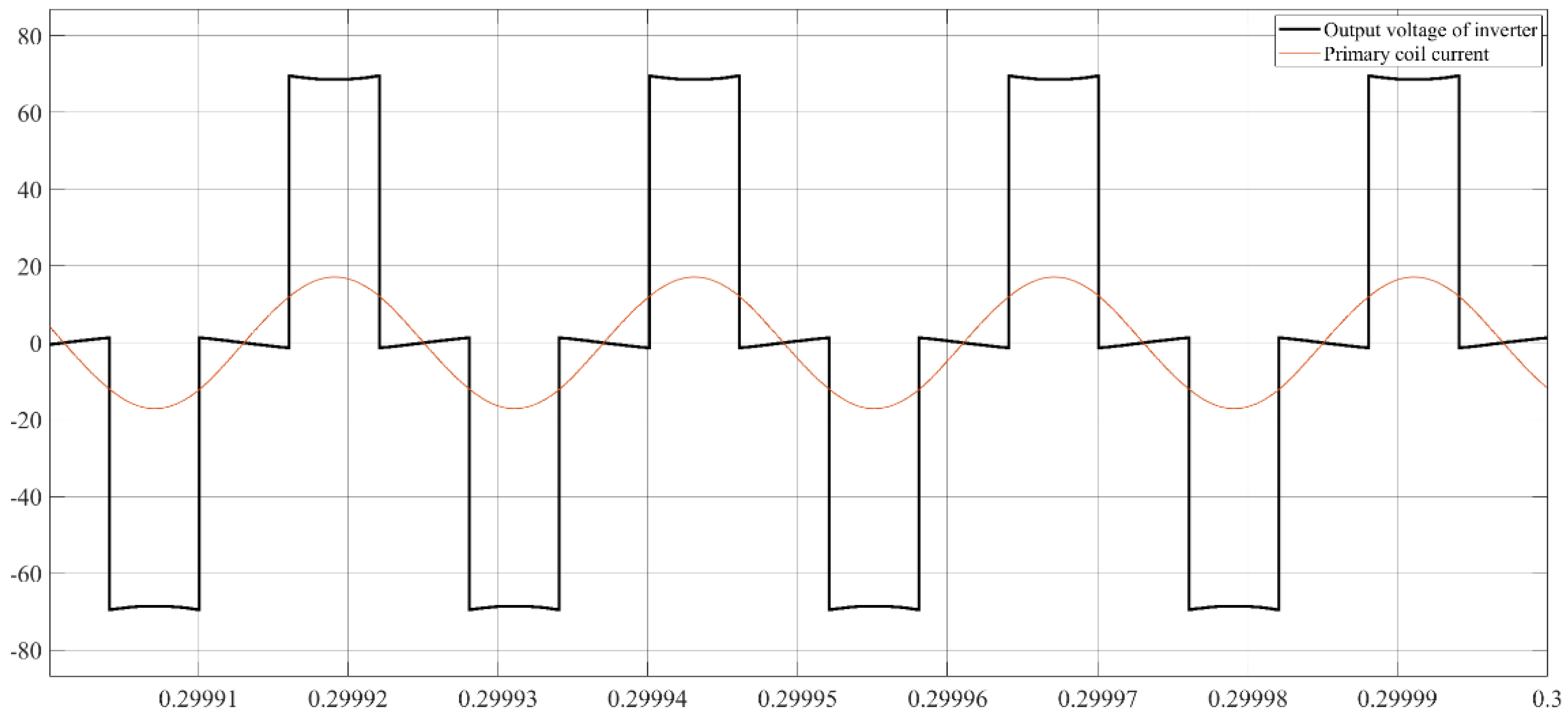
Figure 9 shows the simulation results of Phase 1. In this simulation, the RMS current reference was 1.4 A, and the controller parameters were Kp = 0.7 and KI = 400. As shown in the results, the system was working under resonant conditions, and the RMS coil current was successfully controlled.
For the secondary closed-loop simulation, the initial voltage of the supercapacitor group was 20 V, and the capacitance of the supercapacitor was 1 F. The input voltage reference was set as 40 V. The results are shown in Figure 10, and the input voltage and inductance current were precisely controlled.
Thus, in sum, the control system efficiency was successfully evaluated.

5. Supercapacitor Wireless Charging Experiment

Based on the above theoretical analysis and simulation verification, the experimental platform was constructed as shown in Figure 11 and used a dsPIC33FJ64GS606 digital controller for power stage control. The supercapacitor was combined with two sets of 25 V/15 F with a 72 V DC power generator as the input source. The parameters of the established experimental platform are shown in Table 2.

5.1. Start-Up Estimation Experiments

Before the power transfer experiments, the startup test of the experimental platform needed to be carried out in two phases. Phase 1: Adjust the inverter switch frequency to ensure that the primary side is working under resonant conditions. Phase 2: Verify that the phase shift on inverter driving signals does not influence the resonant state. Figure 12 and Figure 13 show the experimental results of phase angles θ = 0 and θ = 30 degrees, respectively, under a switching frequency of 85 kHz. There was no phase shift between the primary coil current and the output voltage of the inverter; thus, the system was working under resonance. At the same time, the phase shift angle did not influence the resonant state. The system startup test was successfully verified.

5.2. Primary Coil RMS Current Control Results

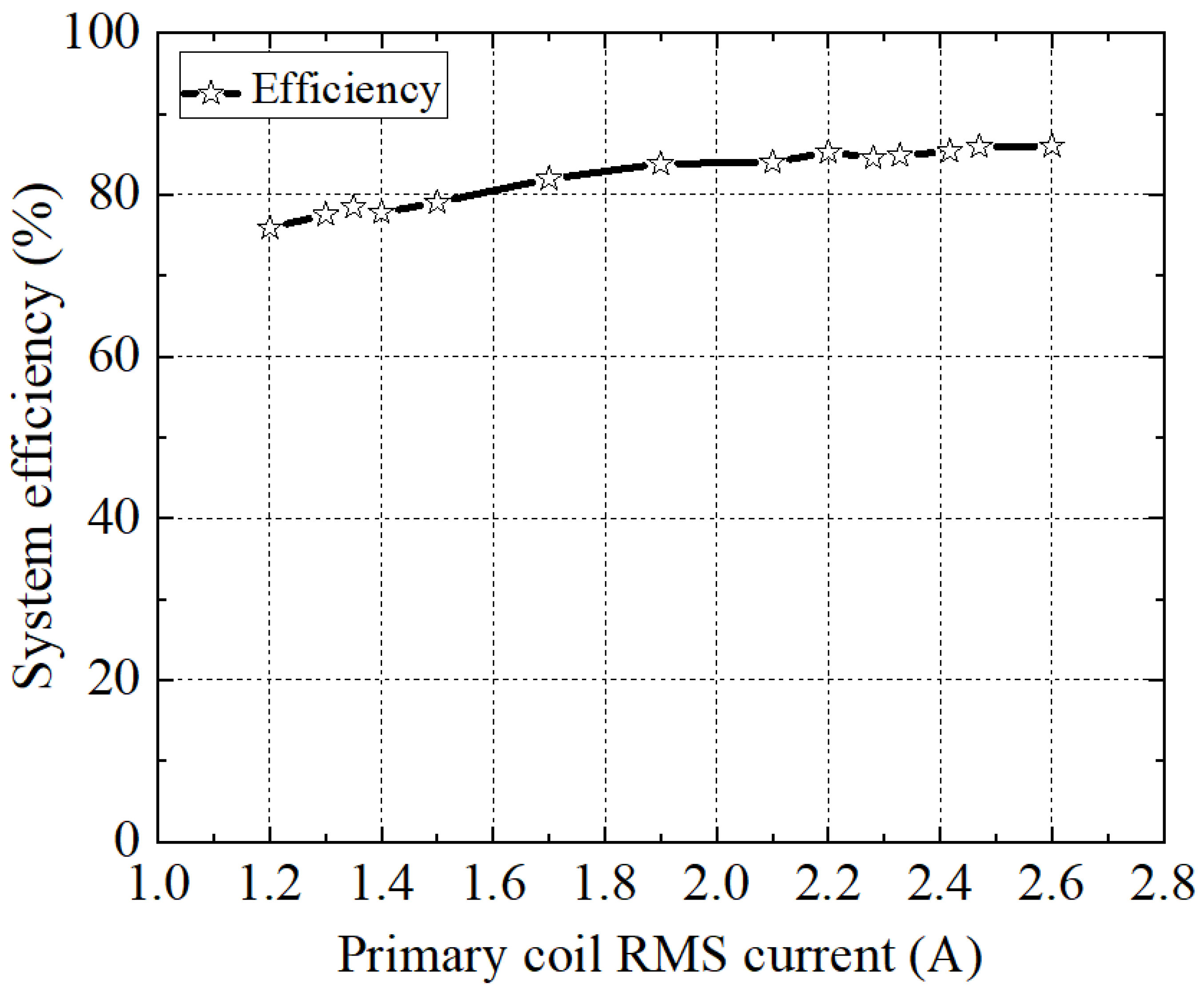
As introduced before, the primary side of the proposed system was working under a resonant state, and the coil RMS current was controlled by the phase shift control method. In this experiment, the transfer distance between the two coils was 4 cm, the input voltage was 72 V constant, and the input voltage of the four-switch buck-boost converter was controlled at 35 V constant. By controlling the coil RMS current from 1.2 A to 2.6 A, the results of the transfer power and system efficiency were as shown in Figure 14 and Figure 15, respectively.
From the results, the input and output power of the proposed system increased with the coil RMS current. Additionally, as the transfer power increased, the transfer efficiency increased slightly, and the RMS current had a positive influence on system efficiency.

5.3. Secondary Side Constant Input Voltage Control Results

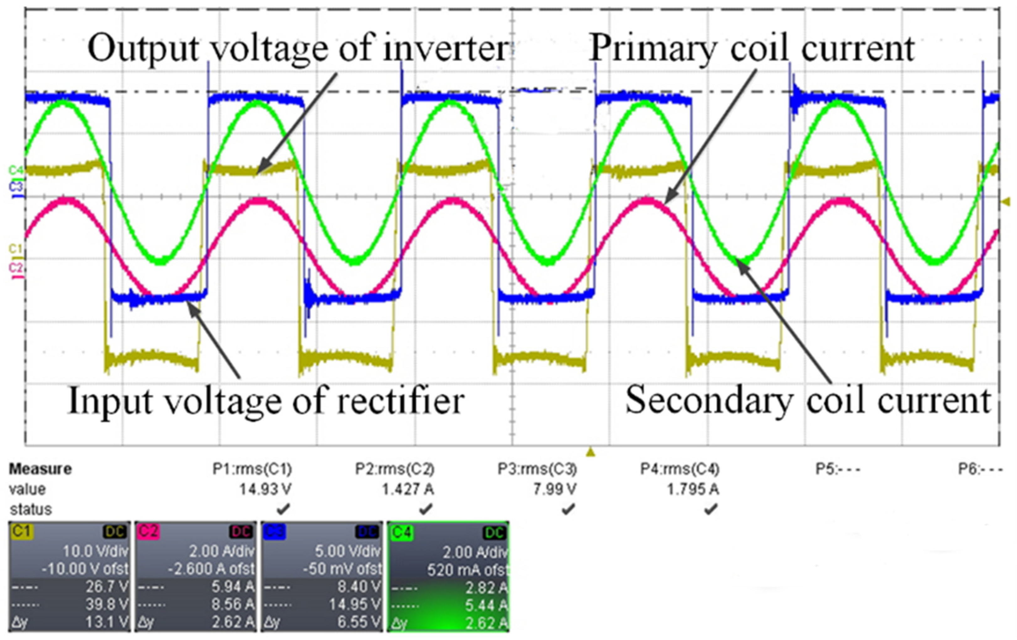
This experiment focused on the secondary side control. The experimental conditions were the same as before, and the primary coil RMS current was controlled at 1.4 A constant. By controlling the input voltage of the four-switch buck-boost converter from 20 V to 48 V, the results were as shown in Figure 16, Figure 17 and Figure 18, respectively.
Figure 16 shows the experimental results of controlling the input voltage of the four-switch buck-boost converter at 20 V. The phase of the current in the primary coil led to that of the inverter output voltage while the secondary side was working under a resonant state. The output power could be calculated as 47 W with input power obtained as 80.4 W.
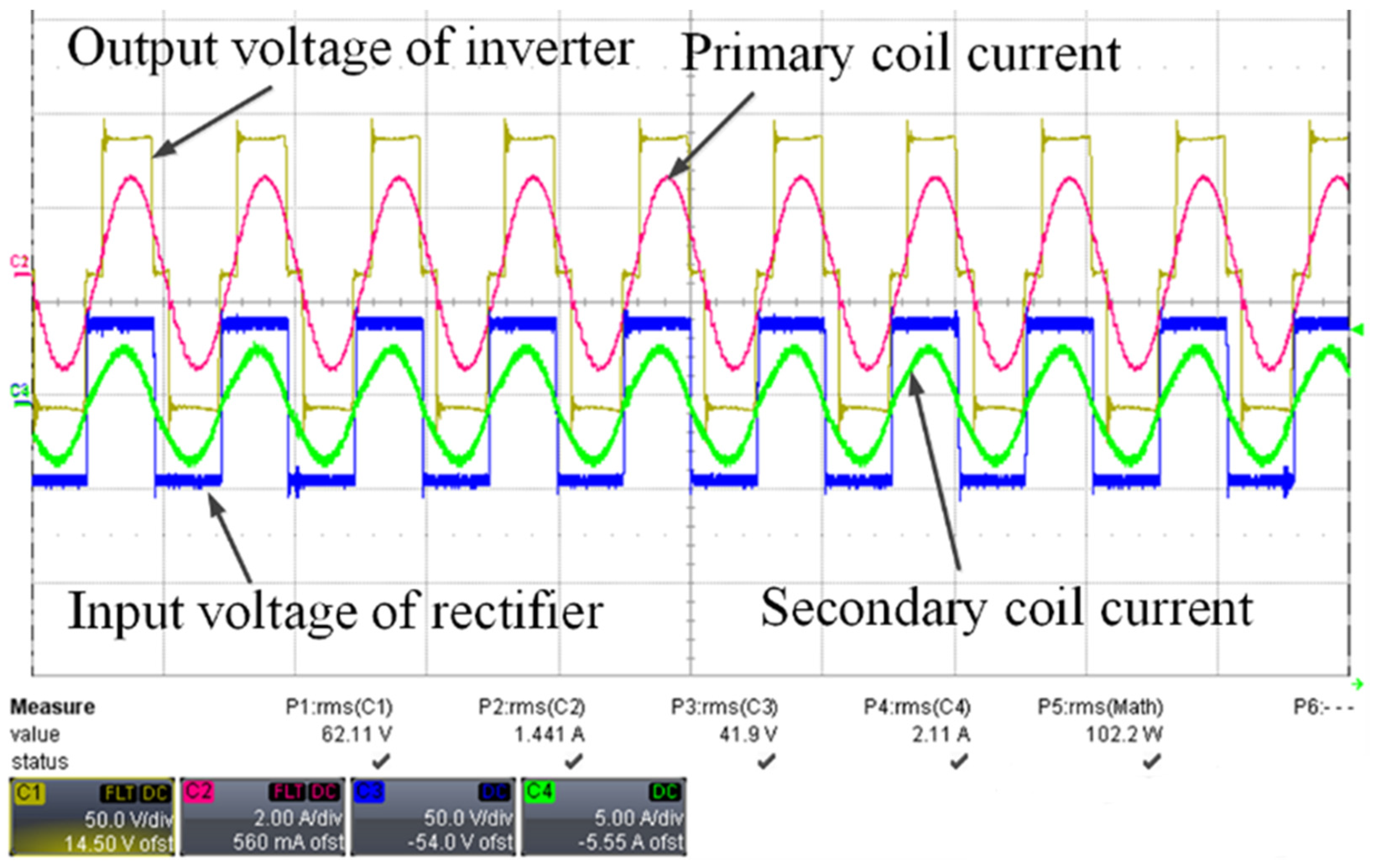
The experimental results of controlling the controlling input voltage of the four-switch buck-boost converter at 40 V are shown in Figure 17, where both the primary and secondary resonant tanks were working under a resonant state. The output power could be calculated as 89 W with input power obtained as 102 W.
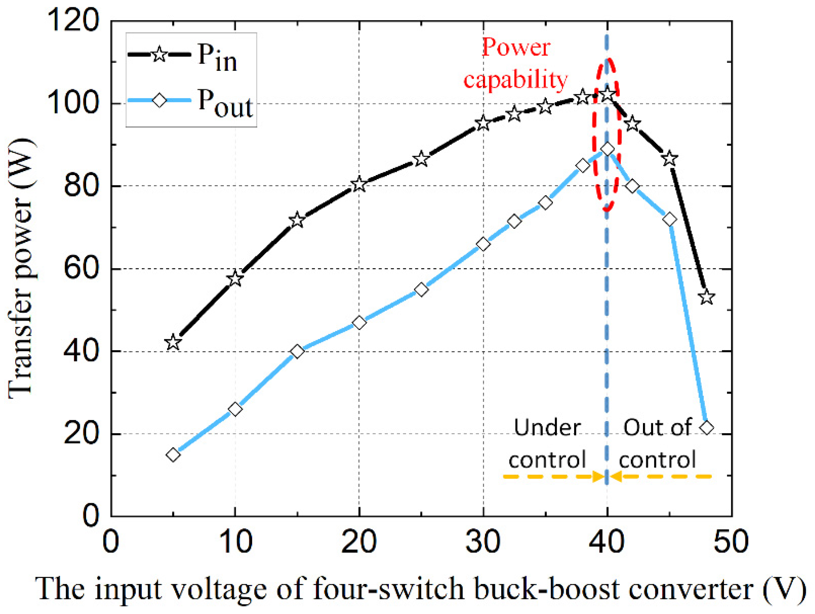
Figure 18 shows the experimental results of controlling the input voltage of a four-switch buck-boost converter at 48 V. Under this condition, the transfer power was outside the input power capacity of the primary coil RMS current; thus, the primary coil current was out of control, and the system was working under an inductive state. The output power could be calculated as 21.5 W with input power of 53.1 W, and the transfer efficiency dropped sharply.
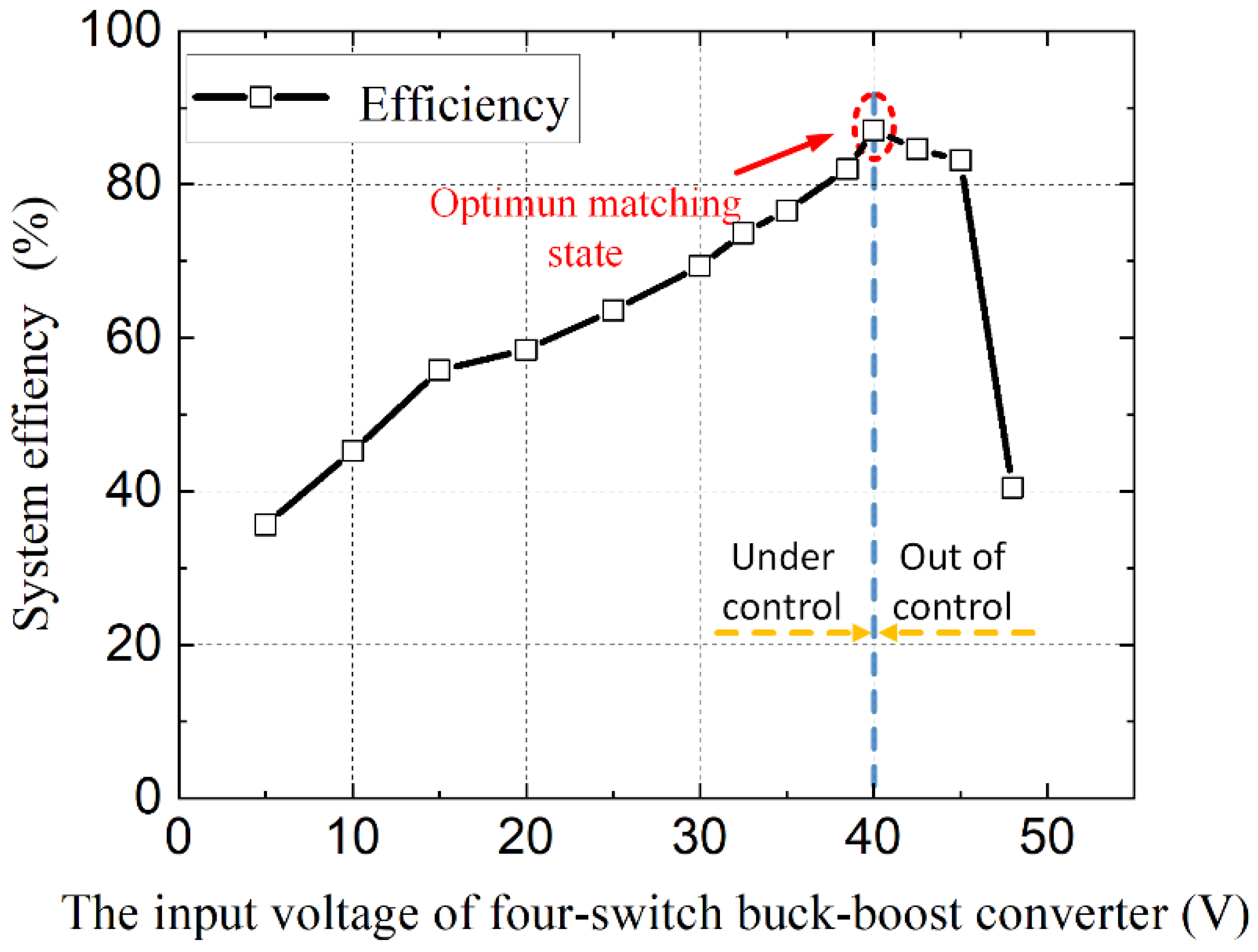
The voltage scanned experimental results of transfer power and system efficiency are shown in Figure 19 and Figure 20, respectively. From the scanned results, the transfer power could be adjusted by controlling the input voltage of the four-switch buck-boost converter but was limited by the primary coil RMS current. If the required transfer power is outside the limit, the transfer efficiency will drop sharply. Additionally, there is a maximum efficiency under each constant primary coil RMS current; under that point, both the transfer power and efficiency will be optimum.

5.4. System Stability to Changes in the Supercapacitor Voltage Results

Considering the charging characteristics of a supercapacitor, the voltage of the super-capacitor keeps rising during the charging process, so it is necessary to check the system’s stability during the charging process.
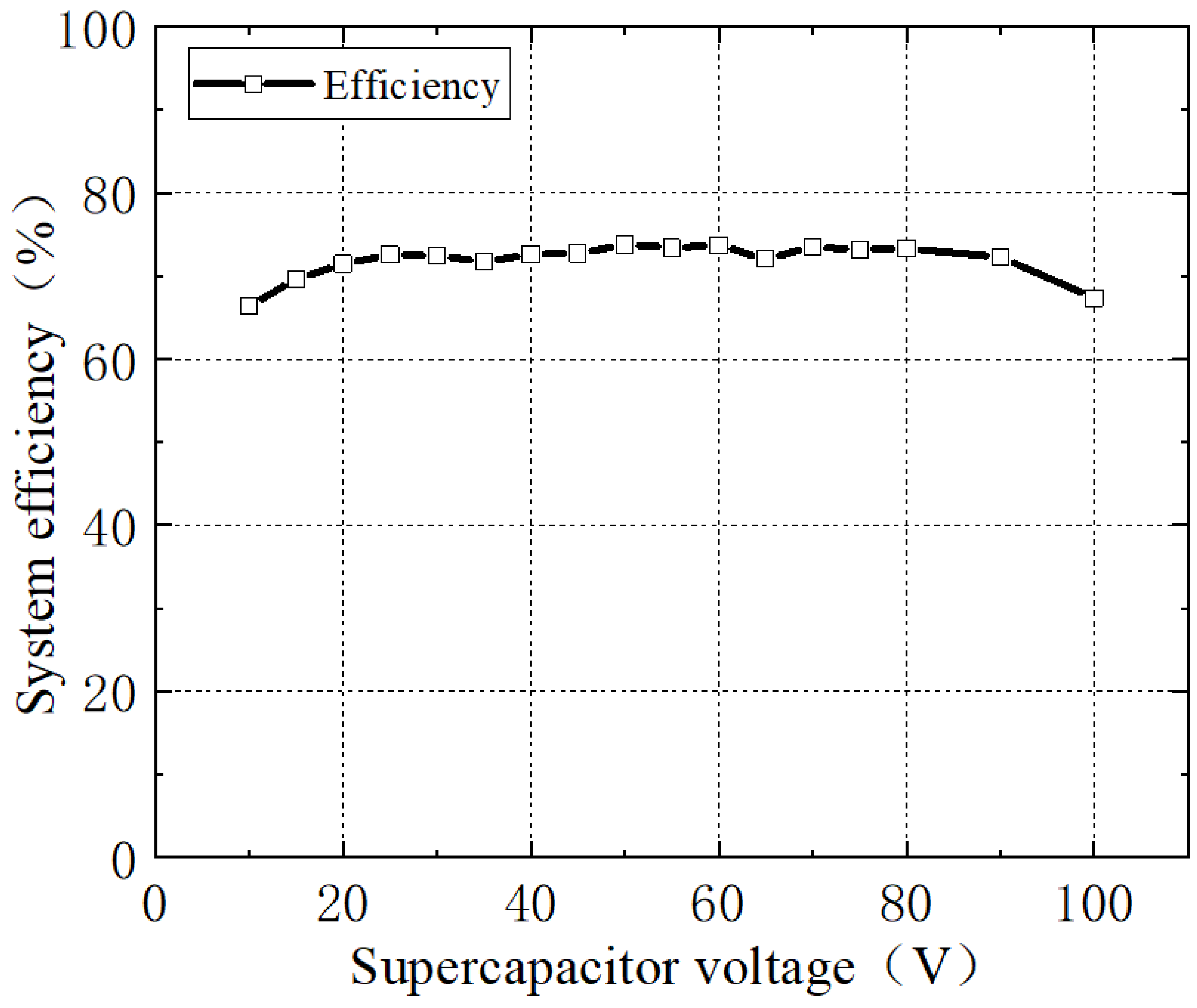
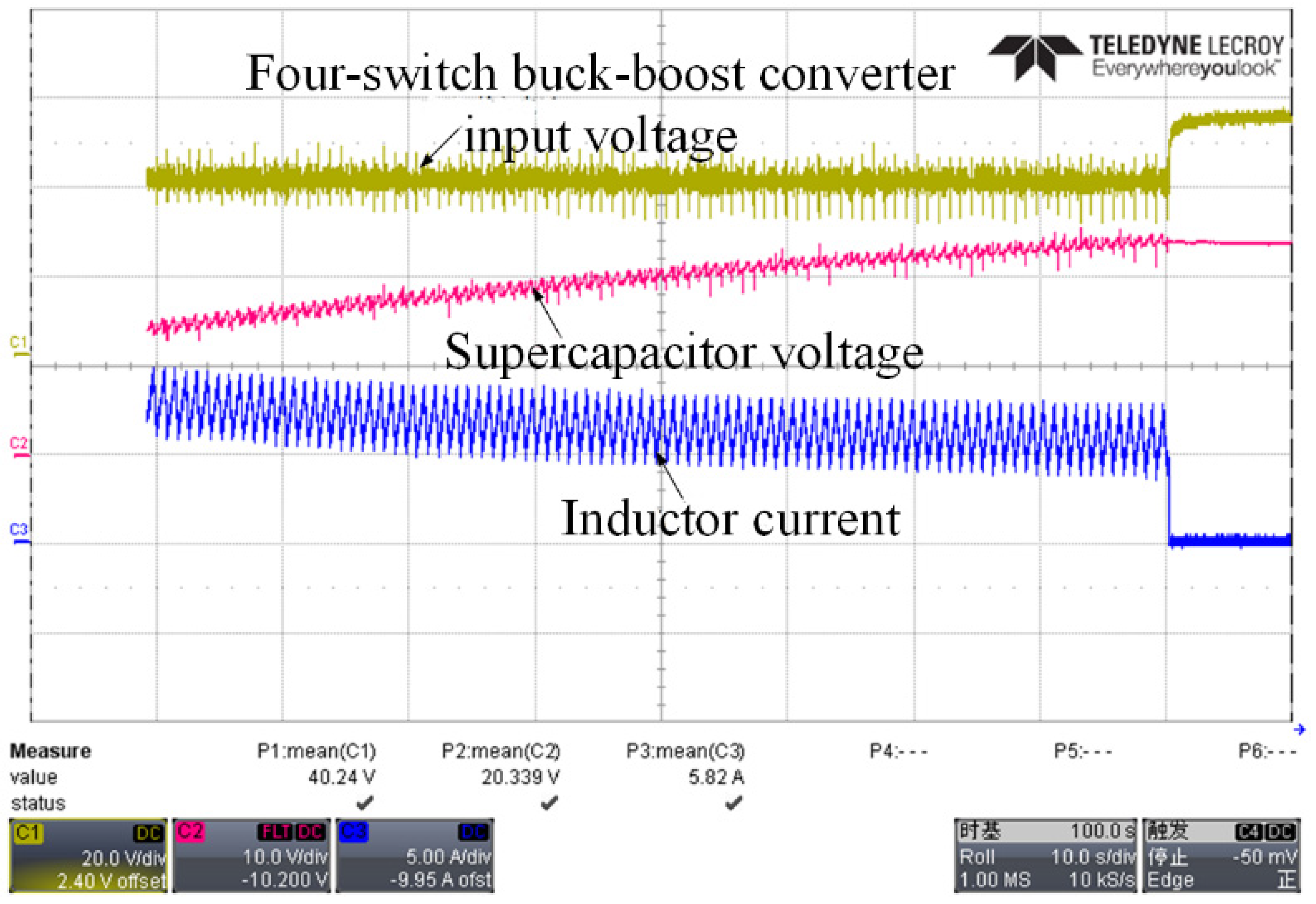
In this experiment, the voltage on the supercapacitor rose from 10 V to 100 V. Under the same conditions as before, the primary coil RMS current was controlled at 1.4 A, and the input voltage of the four-switch buck-boost converter was controlled at 40 V. The results for the inductor current (charging current) and system efficiency are shown in Figure 21 and Figure 22, respectively.
During the charging process, the charging current decreases smoothly while the voltage increases; the most important point is that the system transfer efficiency is not affected by the supercapacitor voltage, and remains almost constant. The waveform of the supercapacitor experimental charging process is shown in Figure 23.

6. Conclusions

In this paper, an LC series resonant WPT system with a modulation control method for supercapacitor charging was proposed. The theoretical analysis of the resonant coupling tank was described in detail with its efficiency and constant current characteristics. A phase shift control method was introduced on the primary side to control the transfer power by controlling the RMS current in the primary coil, while on the secondary side, the received power was controlled by adjusting the input voltage of a four-switch buck-boost load matching converter with a duty cycle modulation control method. The simulation model was established in the MATLAB/SIMULINK environment, and a dsPIC33FJ64GS606-based experimental platform was constructed. Both the simulation and experimental results successfully evaluated the characteristics of the proposed system and verified the control efficiency. Additionally, the system stability during the charging process was successfully confirmed.

Author Contributions

Conceptualization, S.X. and Z.W.; methodology, S.X. and Z.W.; software, S.X. and Z.W.; validation, S.X. and Z.W.; formal analysis, S.X. and Z.W.; investigation, S.X. and Z.W.; resources, S.X. and Z.W.; data curation, S.X. and Z.W.; writing—original draft preparation, S.X. and Z.W.; writing—review and editing, W.J. and J.C.; visualization, S.X.; supervision, S.X. and W.J.; project administration, W.J. and J.C.; funding acquisition, J.C. All authors have read and agreed to the published version of the manuscript.

Funding

This research received no external funding.

Data Availability Statement

Not applicable.

Conflicts of Interest

The authors declare no conflict of interest.

References

  1. Wang, S. Research on a New Lithium Battery Applied in Onboard Energy Storage Device of Light Rail Vehicle. In Proceedings of the 2018 2nd IEEE Advanced Information Management, Communicates, Electronic and Automation Control Conference (IMCEC), Xi’an, China, 25–27 May 2018. [Google Scholar]
  2. Castaings, A.; Caron, H.; Kharrat, H.; Ovalle, A.; Vulturescu, B. Energy Storage System based on Supercapacitors for a 750 V DC railway power supply. In Proceedings of the 2018 IEEE International Conference on Electrical Systems for Aircraft, Railway, Ship Propulsion and Road Vehicles & International Transportation Electrification Conference (ESARS-ITEC), Nottingham, UK, 7–9 November 2018; pp. 1–5. [Google Scholar]
  3. Ayad, M.Y.; Becherif, M.; Henni, A.; Aboubou, A.; Wack, M. Sliding mode control and Unit Power Factor applied to embarked supercapacitors for electrical train traction. In Proceedings of the 2010 IEEE International Symposium on Industrial Electronics, Bari, Italy, 4–7 July 2010; pp. 2163–5145. [Google Scholar]
  4. Cheng, L.; Acuna, P.; Wei, S.; Fletcher, J.; Wang, W.; Jiang, J. Fast-Swap Charging: An Improved Operation Mode For Catenary-Free Light Rail Networks. IEEE Trans. Veh. Technol. 2018, 67, 2912–2920. [Google Scholar] [CrossRef]
  5. Covic, G.A.; Boys, J.T. Modern trends in inductive power transfer for transportation applications. IEEE J. Emerg. Sel. Top. Power Electron. 2013, 1, 28–41. [Google Scholar] [CrossRef]
  6. Huh, J.; Lee, S.W.; Lee, W.Y.; Cho, G.H. Narrow-width inductive power transfer system for online electrical vehicles. IEEE Trans. Power Electron. 2011, 26, 3666–3679. [Google Scholar] [CrossRef]
  7. Shin, J.; Shin, S.; Kim, Y.; Ahn, S.; Lee, S.; Jung, G.; Jeon, S.; Cho, D. Design and implementation of shaped magnetic-resonance-based wireless power transfer system for roadway-powered moving electric vehicles. IEEE Trans. Power Electron. 2014, 61, 1179–1192. [Google Scholar] [CrossRef]
  8. Wang, Y.; Zhang, L.; Hou, H.; Xu, W.; Duan, G.; He, S.; Liu, K.; Jiang, S. Recent progress in carbon-based materials for supercapacitor electrodes: A review. J. Mater. Sci. 2021, 56, 173–200. [Google Scholar] [CrossRef]
  9. Yin, J.; Zhang, W.; Alhebshi, N.A.; Salah, N.; Alshareef, H.N. Synthesis strategies of porous carbon for supercapacitor applications. Small Methods 2020, 4, 1900853. [Google Scholar] [CrossRef]
  10. Cheng, F.; Yang, X.; Zhang, S.; Lu, W. Boosting the supercapacitor performances of activated carbon with carbon nanomaterials. J. Power Sources 2020, 450, 227678. [Google Scholar] [CrossRef]
  11. Saikia, B.K.; Benoy, S.M.; Bora, M.; Tamuly, J.; Pandey, M.; Bhattacharya, D. A brief review on supercapacitor energy storage devices and utilization of natural carbon resources as their electrode materials. Fuel 2020, 282, 118–196. [Google Scholar] [CrossRef]
  12. Kandasamy, M.; Sahoo, S.; Nayak, S.K.; Chakraborty, B.; Rout, C.S. Recent advances in engineered metal oxide nanostructures for supercapacitor applications: Experimental and theoretical aspects. J. Mater. Chem. A 2021, 9, 17643–17700. [Google Scholar] [CrossRef]
  13. Yassine, M.; Fabris, D. Performance of Commercially Available Supercapacitors. Energies 2017, 10, 1340. [Google Scholar] [CrossRef] [Green Version]
  14. Münchgesang, W.; Meisner, P.; Yushin, G. Supercapacitors specialities-Technology review. AIP Conf. Proc. 2014, 1597, 196–203. [Google Scholar]
  15. Zhu, F.; Yang, Z.; Zhao, Z.; Lin, F. Two-Stage Synthetic Optimization of Supercapacitor-Based Energy Storage Systems, Traction Power Parameters and Train Operation in Urban Rail Transit. IEEE Trans. Veh. Technol. 2021, 70, 8590–8605. [Google Scholar] [CrossRef]
  16. Fedele, E.; Pasquale, A.D.; Iannuzzi, D.; Pagano, M. Integration of Onboard Batteries and Supercapacitors Based on the Multi-Source Inverter for Light Rail Vehicle. In Proceedings of the 2022 International Power Electronics Conference (IPEC-Himeji 2022—ECCE Asia), Himeji, Japan, 15–19 May 2022; pp. 698–704. [Google Scholar]
  17. Yıldırım, D.; Akşit, M.H.; Yolaçan, C.; Pul, T.; Ermiş, C.; Aghdam, B.H.; Çadırcı, I.; Ermiş, M. Full-Scale Physical Simulator of All SiC Traction Motor Drive With Onboard Supercapacitor ESS for Light-Rail Public Transportation. IEEE Trans. Ind. Electron. 2020, 67, 6290–6630. [Google Scholar] [CrossRef]
  18. Li, J.; Xin, D.; Wang, H.; Liu, C. Application of Energy Storage System in Rail Transit: A Review. In Proceedings of the 2022 International Conference on Power Energy Systems and Applications (ICoPESA), Virtual Conference, 25–27 February 2022; pp. 539–552. [Google Scholar]
  19. Chu, A.; Braatz, P. Comparison of commercial supercapacitors and high-power lithium-ion batteries for power-assist applications in hybrid electric vehicles: I. Initial characterization. J. Power Sources 2002, 112, 236–246. [Google Scholar] [CrossRef]
  20. Yasha, P.; Vahidi, A.; Fayazi, S.A. Heuristic versus optimal charging of supercapacitors, lithium-ion, and lead-acid batteries: An efficiency point of view. IEEE Trans. Control Syst. Technol. 2018, 26, 167–180. [Google Scholar]
  21. Yang, H. Analysis of supercapacitor charge redistribution through constant power experiments. In Proceedings of the 2017 IEEE Power & Energy Society General Meeting, Chicago, IL, USA, 16–20 July 2017; pp. 1–5. [Google Scholar]
  22. Şahİn, M.E.; Blaabjerg, F.; Sangwongwanİch, A. Modelling of supercapacitors based on simplified equivalent circuit. CPSS TPEA 2021, 6, 31–39. [Google Scholar] [CrossRef]
  23. Guo, W.; Yu, C.; Li, S.; Qiu, J. Toward commercial-level mass-loading electrodes for supercapacitors: Opportunities, challenges and perspectives. Energy Environ. Sci. 2021, 14, 576–601. [Google Scholar] [CrossRef]
  24. Zhang, S.; Pan, N. Supercapacitors Performance Evaluation. Adv. Energy Mater. 2015, 5, 1401401. [Google Scholar] [CrossRef]
  25. Zhu, Q.; Zhao, D.; Cheng, M.; Zhou, J.; Owusu, K.A.; Mai, L.; Yu, Y. A new view of supercapacitors: Integrated supercapacitors. Adv. Energy Mater. 2019, 9, 1901081. [Google Scholar] [CrossRef]
  26. Geng, Y.; Yang, Z.; Lin, F. Design and Control for Catenary Charged Light Rail Vehicle Based on Wireless Power Transfer and Hybrid Energy Storage System. IEEE Trans. Power Electron. 2020, 35, 7894–7903. [Google Scholar] [CrossRef]
  27. Li, Y.; Mai, R.; Lin, T.; Liu, Y.; Li, Y.; He, Z.; Yu, J. Design and implementation of a novel WPT system for railway applications. In Proceedings of the 2017 IEEE PELS Workshop on Emerging Technologies: Wireless Power Transfer (WoW), Chongqing, China, 20–22 May 2017; pp. 213–221. [Google Scholar]
  28. Song, K.; Zhu, C.; Koh, K.E.; Imura, T.; Hori, Y. Wireless power transfer for running EV powering using multi-parallel segmented rails. In Proceedings of the 2015 IEEE PELS Workshop on Emerging Technologies: Wireless Power (2015 WoW), Daejeon, Korea, 5–6 June 2015; pp. 1–6. [Google Scholar]
  29. Pang, J.; Li, Z.; Xu, C. Design of Automatic Switch of Charging Rail for Electric Vehicle Dynamic Charging System Based on Wireless Power Transmission. In Proceedings of the 2021 IEEE International Conference on Advances in Electrical Engineering and Computer Applications (AEECA), Dalian, China, 27–28 August 2021; pp. 731–737. [Google Scholar]
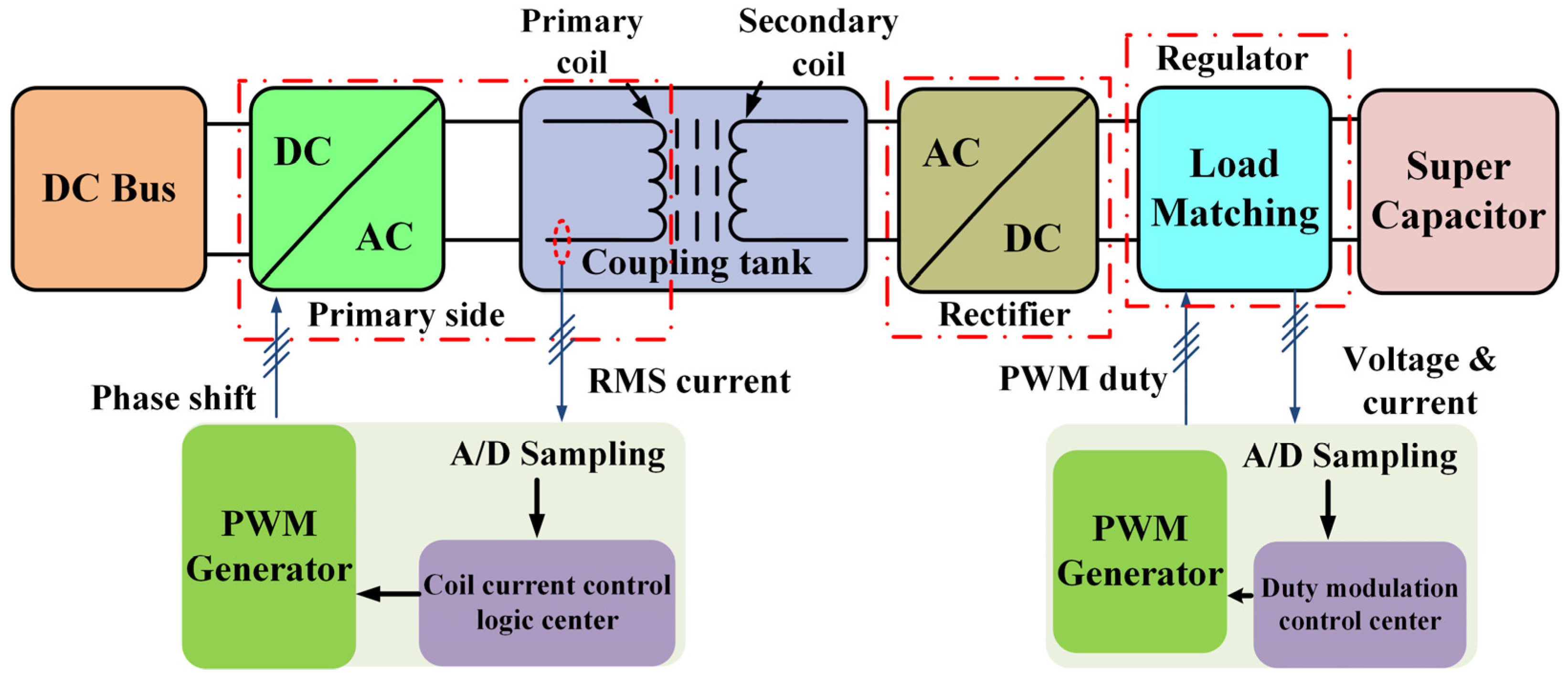
Figure 1. The proposed supercapacitor wireless charging system.
Energies 15 06739 g001
Figure 2. The proposed supercapacitor charging system topology.
Energies 15 06739 g002
Figure 3. T-type equivalent circuit of LC series resonant coupling tank.
Energies 15 06739 g003
Figure 4. Full system equivalent circuit.
Energies 15 06739 g004
Figure 5. Block diagram of the primary side closed-loop control.
Energies 15 06739 g005
Figure 6. Block diagram of the closed-loop controller.
Energies 15 06739 g006
Figure 7. The simulation system.
Energies 15 06739 g007
Figure 8. The open-loop characteristics of 3D scanning results.
Energies 15 06739 g008
Figure 9. The primary inductor current waveform and inverter output voltage waveform.
Energies 15 06739 g009
Figure 10. The simulation waveforms of the input voltage, output voltage and inductor current.
Energies 15 06739 g010
Figure 11. The experimental platform.
Energies 15 06739 g011
Figure 12. The experimental waveform at resonance.
Energies 15 06739 g012
Figure 13. The experimental waveform when the phase shift angle is 30°.
Energies 15 06739 g013
Figure 14. System transfer power vs. primary coil RMS current.
Energies 15 06739 g014
Figure 15. System efficiency vs. primary coil RMS current.
Energies 15 06739 g015
Figure 16. Experimental results with the secondary DC input voltage controlled at 20 V.
Energies 15 06739 g016
Figure 17. Experimental waveform when the input voltage of the DC-DC power conditioner is 40 V.
Energies 15 06739 g017
Figure 18. Experimental waveform when the input voltage of the DC-DC power conditioner is 48 V.
Energies 15 06739 g018
Figure 19. Transfer power vs. input voltage of the four-switch buck-boost converter.
Energies 15 06739 g019
Figure 20. Transfer efficiency vs. input voltage of the four-switch buck-boost converter.
Energies 15 06739 g020
Figure 21. System efficiency vs. supercapacitor voltage during the charging process.
Energies 15 06739 g021
Figure 22. Inductor current vs. supercapacitor voltage during the charging process.
Energies 15 06739 g022
Figure 23. Supercapacitor charging process.
Energies 15 06739 g023
Table 1. The simulation parameters.
ParametersValue
Input supply voltage Vin72 V
Inverter switching frequency fs 85 kHz
Load matching converter switching frequency fdc40 kHz
Inductance L220 μH
Primary resonant inductance Lp500 μH
Primary capacitor Cp 32 nF
Secondary inductance Ls100 μH
Secondary capacitor Cs4 μF
Resonant frequency fr85 kHz
Table 2. The environment parameters.
ComponentsPattern/Parameter
Digital controllerdsPIC33FJ64GS606
Driving power supplierKA7805, FSL336
Current sensor56200C, CHCS-GB5-50A
Primary inductance Lp 500 μH
Primary capacitor Cp 7 nF
Secondary inductance Ls 43.6 μH
Resonant frequency fr 85.07 kHz
Secondary capacitor Cs 0.1 μF
Supercapacitor25 V/15 F
Publisher’s Note: MDPI stays neutral with regard to jurisdictional claims in published maps and institutional affiliations.