Review

A Review on Heat Extraction Devices for CPVT Systems with Active Liquid Cooling

by
Karolina Papis-Frączek
* and
Krzysztof Sornek
Department of Sustainable Energy Development, Faculty of Energy and Fuels, AGH University of Science and Technology, 30-059 Kraków, Poland
*
Author to whom correspondence should be addressed.
Energies 2022, 15(17), 6123; https://doi.org/10.3390/en15176123
Submission received: 31 July 2022 / Revised: 19 August 2022 / Accepted: 19 August 2022 / Published: 23 August 2022
(This article belongs to the Special Issue Energy Performance of the Photovoltaic Systems)

Abstract

:
Numerous numerical and experimental studies have been conducted regarding the Concentrated Photovoltaic Thermal (CPVT) system because of its significant potential for efficient conversion of solar energy. The overall efficiency of the CPVT system is strongly dependent on the device, which extracts excess heat from photovoltaic cells. The most efficient cooling technology involves active cooling, which means that heat is collected from the PV cell via the forced flow of heat transfer fluid. This research paper provides an extensive discussion on devices dedicated to active-cooling CPVT systems, taking into account the latest solutions. First, a short introduction regarding CPVT systems and their main components is presented. The second part of this study presents state-of-the-art solutions in the field of heat extraction devices for the active cooling of photovoltaic cells. The available solutions are classified into two main groups depending on the scale of internal channels: macro- and micro-. Each geometry of the heat receiver is juxtaposed with the corresponding concentrating element, photovoltaic cell, concentration ratio, heat transfer fluid, and operating parameters of the specified system. In addition, this paper discusses the advantages and disadvantages of various devices for heat extraction and provides a comparative study of these devices. Finally, a set of recommendations for CPVT cooling devices is provided.

1. Introduction

1.1. Utilization of Solar Energy

Solar energy is considered the cleanest and most promising energy source among all renewables. Solar radiation is widely available on the Earth’s surface with a significant total amount. The annual energy use for the whole world in 2020 was 557 EJ [1], while the annual potential for solar energy is 1575–49,837 EJ [2]. This means that annual energy consumption is negligible compared to hourly irradiation reaching the exterior of the Earth [3]. Generally, the wavelengths of the solar spectrum cover three main bands: ultra-violet light (290–380 nm and 2% of total solar radiation), visible light (380–780 nm and 47% of total solar radiation), and infrared light (780–2500 nm and 51% of total solar radiation) [4]. Due to this, it is possible to convert solar radiation to electricity using photovoltaic (PV) cells and to thermal energy utilizing solar thermal collectors. Harnessed energy may be used for domestic, commercial, or industrial applications. Nevertheless, there are two main drawbacks of solar energy harvesting. Firstly, the density of solar radiation is relatively small and strongly depends on various factors, including geographic, climatic, and meteorological conditions. Second, commercially available technologies for the conversion of solar energy, especially to electricity, are characterized by relatively low efficiency [5,6]. Typically, the most popular crystalline silicon photovoltaic cells convert 14–27% of the absorbed solar radiation into electricity [4] and achieve higher efficiencies than polycrystalline and thin film cells. Furthermore, high PV cell temperature negatively influences its nominal operating parameters by decreasing open circuit voltage and slightly increasing short circuit current [7]. Due to this, the conversion efficiency of the crystalline silicon PV cell is reduced by 0.2–0.65% for every 1 °C increase in the operating temperature [8]. Among all PV technologies, multi-junction (MJ) cells are characterized by the highest electrical efficiency of 47.1%. This is because of their multi-layer structure, such as GaInP/GaAs or GaInAsP/GaInAs, which includes materials with different bandgaps, so the broader part of the solar spectrum could be converted to electricity. They are also less influenced by the increase in temperature, by 0.245%/°C [9]. However, MJ cells are not commercially available due to high prices and specific installation requirements [10]. Low energy density combined with relatively low efficiency leads to high investment costs and significant area demand compared to their installed capacity. To overcome the mentioned disadvantages, the basic technologies of photovoltaic panels and thermal collectors can be combined with each other, creating hybrid photovoltaic–thermal (PVT) systems [11], which aim to extract the heat generated in PV cells [12]. Moreover, the PVT device allows for producing more energy per unit of occupied space in comparison to the separate conventional solar systems [13]. However, the extracted thermal energy is characterized by a low temperature in the 40–60 °C range [6,7] and therefore may be used in a limited number of applications, such as water and space heating, solar cooling and solar stills [14]. Another way to increase the effectiveness of solar energy harvesting and reduce the overall investment cost is to add an inexpensive optical element [15] such as a mirror, lens, or reflector to the system, which concentrates solar radiation on a small area. Generally, these installations are classified as concentrated photovoltaic (CPV) [16], concentrated solar power (CSP) [17,18,19], concentrated thermal (CT) [20,21] and concentrated photovoltaic thermal (CPVT) [22,23,24]. The evolution of basic solar energy technologies in a CPVT system is shown in Figure 1.
Generally, CPV systems generate more electrical power per unit area than PVs without solar concentration [6] and require sun-tracking mechanisms because they can only exploit direct irradiance [25]. Nevertheless, concentrated solar irradiance causes high levels of heat generation in PV cells and high and non-uniform PV cell surface temperature. Consequently, unfavorable operating conditions could degrade or even destroy PV cells [8]. Therefore, the electrical efficiency and life span of PV cells may be enhanced by appropriate thermal management. The desired silicone-based cell temperature is about 40 °C, while for multi-junction-based solar cells it is less than 80 °C [7,26]. Some research shows that multi-junction solar cells can maintain reasonable efficiency even at temperatures up to 240 °C [27].

1.2. Cooling of PV Cells

There are a wide variety of cooling techniques that could be applied for the cooling of solar cells [28]. Thermal management in a concentrated system could be based on pre-illumination and/or post-illumination heat extraction. The first concept uses filters, which decompose the sun spectrum before it reaches the PV cells and blocks specified wavelengths. This is a promising but not mature technology [7]. A review of the CPVT systems based on the spectral beam splitting technology may be found in [29]. The post-illumination approach incorporates the heat receivers, which collect the heat from the solar cell. Heat extraction is limited by the operating temperature of the cell and the quality of contact between the photovoltaic cell and the cooling unit [7]. The energy flow in pre- and post-illuminating techniques is shown in Figure 2.
The post-illumination techniques include two main approaches: passive and active cooling. Passive cooling is based on heat dissipation from the photovoltaic cell through unforced processes such as natural convection (heat sinks with finned metal strips) or phase change processes (heat pipes, phase change materials (PCM)) [30]. The most common approach incorporates heat sinks made of silicon, aluminum, or copper which are cooled by air [7]. Usually, passive cooling is used for installations with a concentration ratio (for more details see Section 2.1) of up to 500, which use a single solar cell [31]. Furthermore, the studies presented in [7] showed that passive cooling is effective even at 10,000 suns, but only for very small PV cells with an area smaller than 1 mm2. The main advantage of passive cooling is the good cost-to-effectiveness ratio, whereas the significant disadvantage is the dissipation of heat.
In the case of active cooling, heat is extracted from the PV cell indirectly, via the forced flow of heat transfer fluid (HTF). Active cooling is characterized by significantly higher convective heat transfer coefficients than passive cooling, which makes it more efficient [30]. The coolant flows through the heat receiver with micro/minicanals, channels/ducts or a jet impingement system. Due to this, active cooling requires additional devices such as fans and pumps. The most common HTFs are water, water–glycol solutions, nanofluids, air, etc. [7]. Active cooling is required in the case of densely packed PV cells under concentrations > 150 suns [31].

2. Concentrating Photovoltaic—Thermal Systems

If the heat absorbed by HTF is collected and used for downstream applications, the CPV system becomes CPVT [30]. This installation resolves the drawbacks of PVT and CPV as separate systems, which are: low-temperature heat recovery and waste heat recovery, respectively [3]. A CPVT simultaneously generates both thermal and electrical energy, which means it classifies as a cogeneration unit. The utilization of solar energy is a cascade process [2], which means that the fraction of the solar spectrum with energy close to the band gap of the photovoltaic cells is converted into electricity and then the remaining part of the solar spectrum may be converted into useful heat (compare with Figure 2). Moreover, CPVT can be transformed into a trigeneration or even polygeneration system by installing external devices [32]. Due to the simultaneous generation of various outputs, the total energy efficiency of the CPVT technology is up to 80% [3,6]. The positive and negative impact of high solar energy density and the active cooling of PV cells is presented in Figure 3.
The advantages and disadvantages of CPVT systems are summarized in Table 1.
Heat harnessed in the CPVT system may find applications in: domestic water preparation [33], fresh water production [14,34,35,36,37], greenhouse heating [38,39], cooling with absorption chillers [40,41,42,43], organic Rankine cycles [44,45,46,47], hydrogen production [45], dyeing in the textile industry [48], solar windows [39] and other building-integrated systems [49]. It should be noted that the CPVT systems operate well in areas where a large amount of direct irradiation is available, i.e., in hot and mixed climate locations. In these locations, solar-driven cooling and air-conditioning systems are especially desirable [50]. The paper [51] presents the concept of a complex polygeneration system based on renewable energy sources, which is dedicated to isolated communities. This setup includes parabolic trough CPVT, PVT collectors, a biomass heater, an absorption chiller, and a desalination system.
Numerous studies have been conducted with regard to the Concentrated Photovoltaic Thermal (CPVT) systems numerically and experimentally because of their significant potential for efficient conversion of solar energy. Available research papers discussed the influence of an optical element, solar cell, heat receiver, HTF, presence of insulation and/or glazing, operating conditions, etc. on the performance of CPVT systems. These review articles summarized the fundamentals, design considerations, current technologies of CPVT systems [18,23], challenges in development [17], thermal management and storage [3], performance assessment, and future directions of CPVT development [24]. In addition, a review of CPVT systems with waste heat recovery (WHR) was carried out in 2017 [2]. Nevertheless, none of the existing articles cover the topic of devices dedicated to heat extraction via active liquid cooling with a special emphasis on their design: shape, material, insulation, etc. Moreover, there is a lack of a comprehensive analysis of the correlation between the characteristics of the heat receiver geometry, used PV cells and the concentrator type. This research paper provides an extensive discussion on devices dedicated to active cooling CPVT systems, taking into account the latest solutions. First, a short introduction regarding CPVT systems and their main components is presented to ensure a theoretical background. The second part of this study presents state-of-the-art solutions in the field of heat extraction devices for the active cooling of photovoltaic cells. The available solutions are classified into two main groups depending on the scale of internal channels: macro- and micro-. Each geometry of the heat receiver is juxtaposed with the corresponding concentrating element, photovoltaic cell, concentration ratio, heat transfer fluid, and operating parameters of the specified system. In addition, this paper discusses the advantages and disadvantages of various devices for heat extraction and provides a comparative study of these devices. Finally, a set of recommendations for CPVT cooling devices is provided.

2.1. Concentrator

CPVT systems come in many varieties, which mainly differ in the shape and size of the concentrator, which consequently determines the properties of other system components, such as: the cooling system, photovoltaic cells, tracking system, overall operating parameters and the system costs. The main task of the concentrator is to collect incident solar radiation and redirect it to a significantly smaller area. Therefore, the concentrator increases the amount of primary solar energy collected by a receiver and reduces the required area of solar cells [3]. The ratio between the concentrator area AC and the receiver area AR is known as the geometrical concentration ratio (CR) [16].
CR = A c A R
This is a characteristic property of the system that cannot be modified after manufacture. However, the distribution of irradiation over the receiver area is not homogeneous: the heat flux is the highest in the central part of the receiver and decreases closer to the edges. The ratio of the average solar heat flux over the receiver area and the concentrator area is known as optical efficiency (ηoptical) [4]. Thus, the total concentrating ability of the system is described by a parameter known as the optical concentration ratio (CRI), which is a result of the multiplication of the geometrical concentration ratio and optical efficiency. The optical concentration ratio is expressed as the “number of suns”, where 1 sun is equivalent to 1000 W/m2 [3]. This unit is also used to define the geometric concentration ratio, especially when optical efficiency is 1 [52]. Based on the concentration ratio, the CPVTs can be classified into four groups: low (CR < 10 sun), medium (10 sun < CR ≤ 100 sun), high (100 sun < CR ≤ 2000 sun) or ultrahigh (CR > 2000 sun) [7], as shown in Table 2. With increasing CR, the output of thermal and electrical power increases and improves the efficiency of the system. Nevertheless, higher CR raises also numerous limitations. The common problem of high and ultra-high CPVT systems is the non-uniform distribution of irradiance and temperature on the receiver area, overheating of PV cells, and significant and optical losses (such as chromatic aberration). Therefore, a system with high CR requires a highly smooth optical element, efficient cooling device, accurate two-axis solar tracking and sometimes even secondary optics. On the contrary, for CPVTs with low CR, active cooling or tracking is not required because they are the only ones that utilize not only direct solar radiation but even diffuse radiation [3].
When taking into consideration the concentrator geometry, the solar radiation may be focused onto a focal line or focal point. The linear focus CPVTs are using compound parabolic reflector, parabolic trough mirror, linear Fresnel reflector, linear Fresnel lens, etc. and they operate with a single-axis tracking mechanism, which rotates the construction around its focal axis [3]. The compound parabolic collector (CPC) uses parabola-shaped mirrors to focus solar radiation onto a relatively wide linear receiver to reach the two focal lines. CPC is a low-concentration technology with CR < 5, which generates medium temperature heat and may be used even without a tracking system [53]. The parabolic trough collector (PTC) also uses linear parabolic optics but in the form of a single reflector. A linear receiver is placed lengthways on the focal line, and it has a rectangular, triangular, or less often a circular or semicircular cross-section [54]. PTC is the most popular and, simultaneously, the most mature solar concentrating technology [55,56]. In the Linear Fresnel Reflector (LFR), narrow flat mirrors, which consist of chains of prisms, are placed in rows, close to ground level. They follow the Sun’s movement always in the east–west plane and focus the solar radiation onto a long, downward-facing, stationary receiver placed above them. The CR usually ranges between 10 and 40. LFR technology is characterized by simplicity of operation and low maintenance costs [57]. Moreover, Fresnel lenses are lightweight and easy to produce at a low cost [58,59].
The point-focus CPVTs are using a parabolic dish collector, spot Fresnel lens, etc. and they operate with a double-axis tracking mechanism. The solar dish collector (SDC) uses a parabolic dish mirror, which concentrates the solar radiation onto a receiver located at the focal point of the system. The receiver may take different shapes such as: cylinder, hemisphere, conic, etc. SDC achieves CR above 100 and this technology is undergoing rapid development [3]. Generally, point-focus systems are able to generate high-temperature heat and can be easily integrated with micro-gas turbines, Stirling engines, etc. [32,60,61] instead of PV cells. Spot Fresnel lenses have circular rows of prisms instead of parallel ones as in the case of linear reflectors [62]. Optical elements for concentrating systems were widely discussed in [63].

2.2. Photovoltaic Cells

The type of photovoltaic cell applied in the CPVT system depends mainly on the concentration ratio and thermal management system [7]. Because of the high irradiance intensity on the surface of the PV cell, there is a high probability that the photovoltaic cell will operate under adverse operating conditions. Hence, the photovoltaic parameters should be characterized by low-temperature coefficients and the material itself should be highly resistant to thermal damage. The most popular crystalline silicon cells are considered suitable for CPVT systems with a low and medium concentration ratio (CR < 100). Studies [64,65] show that the single-crystalline silicon solar cell works optimally under CR = 4. For a higher CR, the decrease in temperature efficiency is compensated by a lower investment cost. The most technologically advanced multi-junction photovoltaic cells operate efficiently only with high concentration ratios (C > 100) [15,28].
When considering an arrangement of solar cells, they could be classified as single-cell, linear, and densely packed cells [66]. A single cell is easy to cool because it does not occupy significant space. The drawback is that a single cell is not capable of generating a significant amount of energy. On the contrary, linear and densely packed PV cells allow high electrical output. However, concentrated irradiation can vary on the surface of PV cells, so the non-uniform temperature would limit the electrical performance of the entire system [25].

2.3. Heat Extraction Device

The heat receiver is the main element of the thermal management system in the CPVT system. It is widely known that the efficiency of PV cells decreases not only as a result of the high operating temperature but also as a consequence of the non-uniform temperature distribution over the PV cells. Therefore, a heat receiver is placed in CPVT systems mainly to increase the efficiency of the photovoltaic cell and to reduce thermal stress [67]. Nevertheless, the receiver should simultaneously produce heat with as high a temperature as reasonably possible, widening its range of applications. Generally, the usage of the collected heat contributes to an increase in the total conversion efficiency of the CPVT system. The most efficient, active cooling systems require pumping power, which as a parasitic loss should be kept to a minimum. Finally, to reduce the manufacturing and maintenance costs, the heat receiver should be characterized by relatively simple geometry and reliable operation under concentrated solar radiation [31]. In CPVT systems, a type of heat extraction device depends mainly on the geometry of the optical element, concentration ratio, the number and dimensions of the PV cell, the specific requirements regarding the temperature of the PV cell, and the weather conditions (harsh or mild). In systems with line focus, the heat receiver is usually in the form of a line pipe, whereas for point-focus systems, the geometry is more compact.
Despite the design of the heat extraction device, the HTF that flows through it plays a significant role. For active cooling, the most popular HTFs are air, water, nanofluids, and oils [68]. Air and water are widely available, inexpensive, and environmentally friendly fluids. Since air has a low heat capacity, water is preferred for cooling purposes. However, in some situations, the use of pure water is limited, and it can be mixed with glycols or nanofluid particles [69]. Water-nanofluid solutions are capable of more intensive heat transfer due to their enhanced heat capacity, improving both thermal and electrical efficiency. The higher the concentration of nanoparticles, the higher the viscosity and consequently the higher the pumping power [70]. To reduce this problem, a study on hydrophobic coatings for microchannel heat sinks was conducted, and the results obtained confirmed a reduction in pressure drop of 17% [71]. In addition, the usage of nanofluids may lead to corrosion of aluminum channels due to the pH of the fluid [72]. Another possibility is to use diathermic oil, especially in installations that work in high-temperature polygeneration systems. Oils also provide an excellent alternative for installations, where water usage is restricted. On the other hand, oils are characterized by high thermal inertia [3]. There are also hybrid solar systems that simultaneously use two heat transfer fluids. The studies presented in [73] showed that the usage of air and water in the PVT system allowed for improving its overall efficiency during the winter months. The advantages and disadvantages of liquid heat transfer fluids are presented in Table 3.
Depending on the temperature of HTF, the extracted heat may be used in various applications, as shown in Figure 4. The low-temperature heat is suitable for domestic applications: water or space heating. When the system operates at higher temperatures (close to 100 °C), it is possible to couple the CPVT system with absorption chillers, ORC cycles or desalination units (membrane distillation requires temperatures from 60 to 90 °C). Higher temperatures can provide heat for industrial processes. Highly efficient absorption chillers operate at temperatures in the range of 80–160 °C. The optimal operating temperature for the CPVT system depends on its main application and the possibilities of heat utilization in specified cases [74,75].

3. Heat Extraction Devices with Macro-Scale Channels/Ducts

This section is dedicated to heat extraction devices with macro-scale channels and ducts. This kind of heat receiver is mainly used in systems with low and medium concentration ratios, due to the limited heat transfer efficiency. However, macro-scale receivers are characterized by non-sophisticated design and therefore are easy to manufacture at relatively low costs.

3.1. Rectangular Ducts

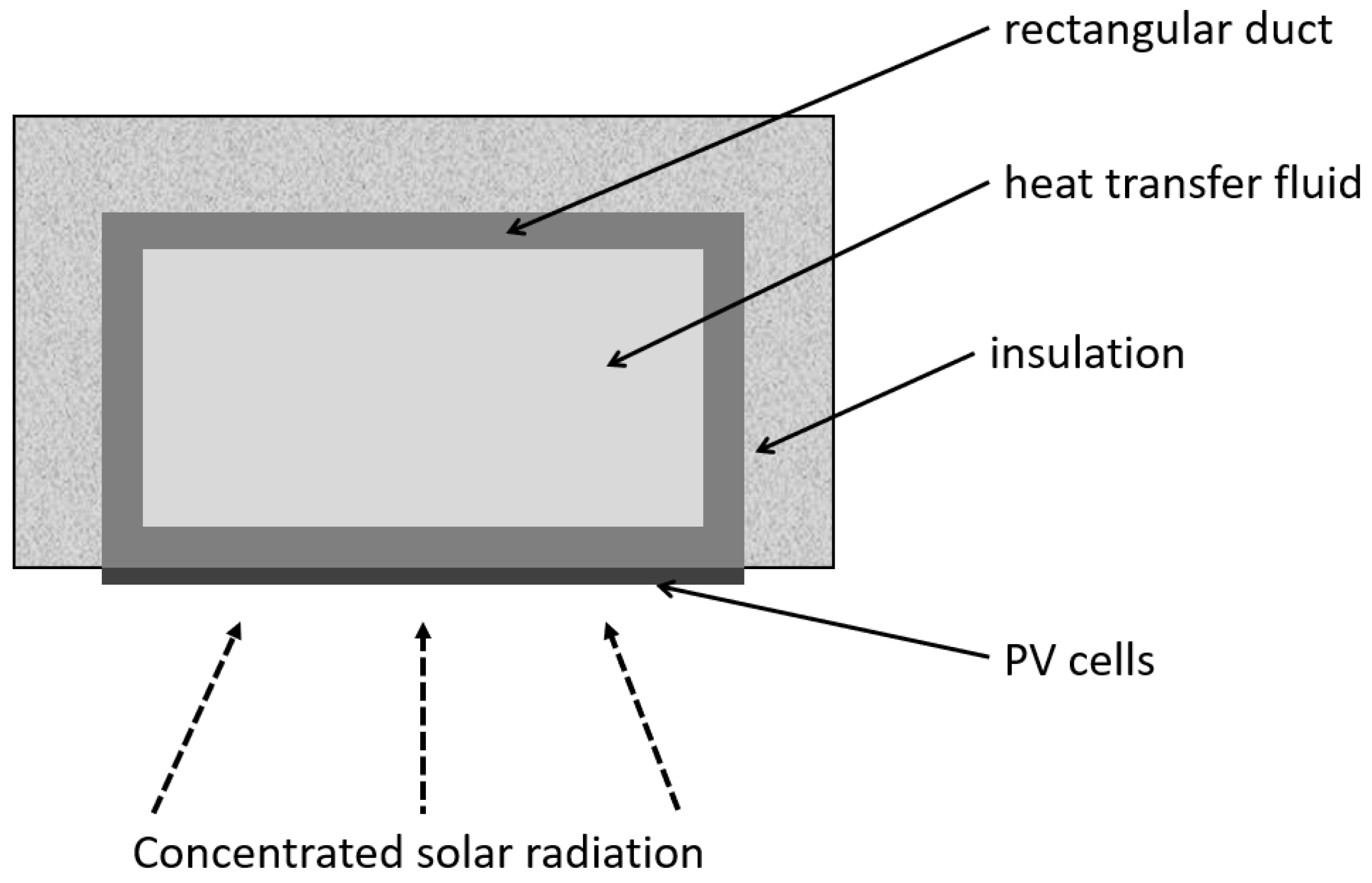
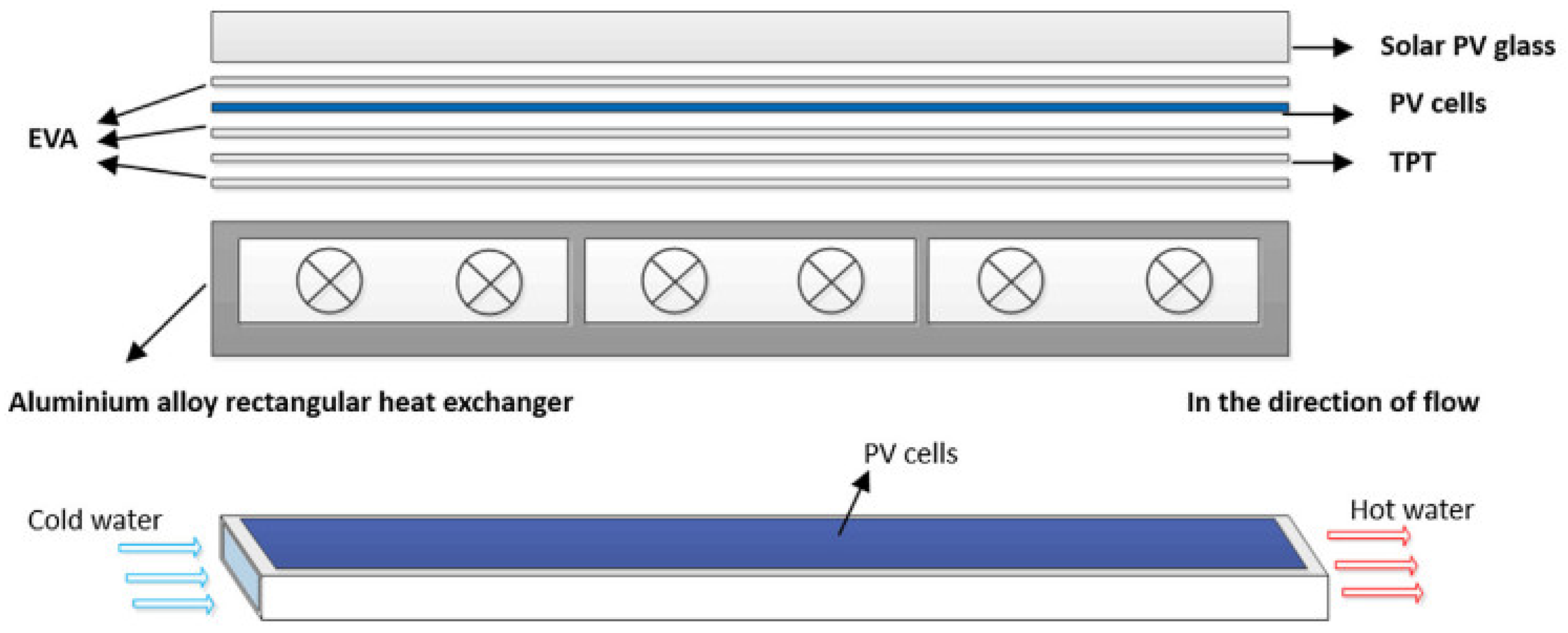
The simplest form of a receiver applied in linear-focus CPVT systems is a rectangular tube, as shown in Figure 5. The HTF flows through the pipe, so the receiver may be considered leakproof. PV cells may be mounted directly on the selected flat surfaces of the ducts without additional absorbers. The most common approach includes one wall covered with PV cells to absorb concentrated solar radiation. However, PV cells may also be placed on other walls to collect non-concentrated irradiation. Generally, a rectangular-duct heat receiver is very popular in numerous research.
A theoretical model of the CPVT system with a V-trough concentrator was presented in [76]. The heat receiver was in the form of a rectangular channel: three walls were made of a bent steel sheet and one was made from the backside of PV cells. The numerical and experimental results revealed that the maximum total efficiency of this system was only 35%, and the authors claimed that this poor performance was caused by a relatively low reflectivity of the steel mirrors and a lack of proper insulation.
In the study [77], low-concentration photovoltaic and PVT systems were experimentally tested in Tozeur, Tunisia. Both systems included a compound parabolic concentrator, whereas the heat receiver was in the form of a rectangular duct. The data obtained confirmed that the cooling system was more efficient and allowed a CFD model to be validated. It was confirmed that changes in the mass flow rate of HTF cause opposite effects on thermal and electrical efficiencies. The authors concluded that further studies should predict possible improvements in receiver geometry.
The authors in [78] evaluated the performance of the compound parabolic CPVT system with CR = 4 to eliminate multiple reflections in the optical system. The system used an aluminum rectangular pipe (insulated at three sides) as a heat receiver and a polycrystalline photovoltaic cell as an electricity generation unit. The results showed that this system may achieve total efficiency of 71%, even if a low-precision tracking system is applied.
In [10], a 6.2 kWp CPVT system with active cooling of triple-junction solar cells was examined. The installation incorporated linear Fresnel lenses (CR = 80) and an aluminum rectangular receiver. A dynamic simulation prepared in Engineering Equation Solver forecasted the annual performance of the system under Phoenix climactic conditions. The average efficiency of the MJ cell was 34.75%, which resulted in the annual generation of electricity and thermal energy of 14 MWh and 5 MWh, respectively.
The potential of a CPVT system with static linear Fresnel lenses (CR = 25) for regulating greenhouse temperature was examined in [79]. The greenhouse glass roof was replaced by Fresnel lenses. Rectangular channels were placed underneath to generate electricity through monocrystalline PV cells and collect thermal energy. Onsite studies revealed the system thermal efficiency of 56% and electric efficiency of 11%. The authors listed possible improvements such as the implementation of antireflective coatings to the glass or lamination of the Fresnel lenses.
Another roof-integrated miniature CPVT system was examined in [80] by mathematical model and experimental tests. The results showed good agreement and allowed for the summary that the CPVT system has a lower heat loss coefficient compared to the traditional flat-plate PVT system mounted on the roof.
Paper [81] numerically evaluated the energy performance of the CPVT system with a rectangular duct. The 2D model of a heat receiver was developed in FORTRAN to estimate the thermal and electrical output under varying wind velocity, inlet fluid temperature and velocity, concentration factor, presence of insulation, nanofluid particles, and direct irradiation. Obtained results were compared with experimental studies and good agreement was found. Variant analysis proved the positive impact of wind velocity on the electrical efficiency of PV cells and the enhancement of heat transfer by nanoparticles (by 15% when the concentration of nanoparticles is 0.2%). Moreover, the thermal efficiency increased by 2% in the case of an insulated receiver. The 2D numerical model of the receiver studied in [81] was developed into a 3D model with coupled 3D–4Rays and a finite volume method [82]. This model aimed to investigate the temperature distributions over the PV cells under a non-uniform irradiance distribution. Hot spots and shading significantly influenced both electrical and thermal efficiency (by more than 6%) of the system.
In summary, rectangular ducts may be applied in CPVT systems with various linear concentrators, i.e., V-trough, compound parabolic, or linear Fresnel lenses. Proper insulation of the receiver walls may provide an increase in thermal efficiency. Due to the relatively wide aperture area, rectangular-duct receivers may be applied in systems with low-precision tracking or could be stationary in roof-integrated applications.

3.2. Circular Ducts

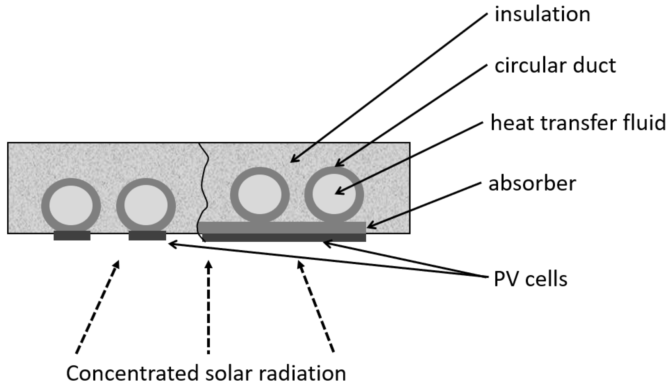
Circular ducts, because of their shape, require a flat plate absorber to enable the mounting of PV cells (see Figure 6). Consequently, the contact area between the absorber and the pipe is reduced. The walls of the circular duct and the bottom of the absorber are usually insulated to reduce thermal losses. This solution is also very popular in linear CPVT systems.
The objective of [83] was to examine the performance of the CPVT system with a parabolic reflector, monocrystalline photovoltaic cells and a flat heat receiver with a circular tube (Figure 7) operating with pure thermal oil or oil–nanoparticle solution. The studies were conducted with SolidWorks Flow Simulation. It was found that for all analyzed cases, the application of nanofluids improved the total efficiency of the system. For the optimum case, the thermal efficiency was 46.84% and the electrical efficiency was 6.60%.
The performance of parabolics through the CPVT system with insulated circular duct was also reported in [84]. For CR = 10.27, monocrystalline silicon, polycrystalline silicon, a Supercell, and a GaAs cell were experimentally tested. The best electrical performance was noted for GaAs cells, whereas the best thermal performance was noted for silicon solar cells. These cells were also tested at CR = 20 and showed electrical and thermal efficiencies of 9.88% and 49.84%, respectively, for GaAs and 7.51% and 42.4%, respectively, for silicon cells. The economic analysis proved that the CPVT system with silicon cells is as economically viable as the PV installation. The same receiver was also investigated in [85] with CR = 30.8 and electrical efficiencies were: 3.63% for Supercells, 8.94% for GaAs cells, and 3.67% for a silicon cell. The highest thermal efficiency of 45.17% was noted for the Supercell case, whereas the lowest was 34.53% for silicon cells. The authors investigated the influence of mirror reflectivity on the electrical performance of the CPVT system. The increase in reflectivity from 0.69 to 0.92 allowed for enhancing the electrical efficiency by 0.9% (Supercell), 2.62% (GaAs) and 5.47% (silicon cell) despite the lower CR = 28.8.
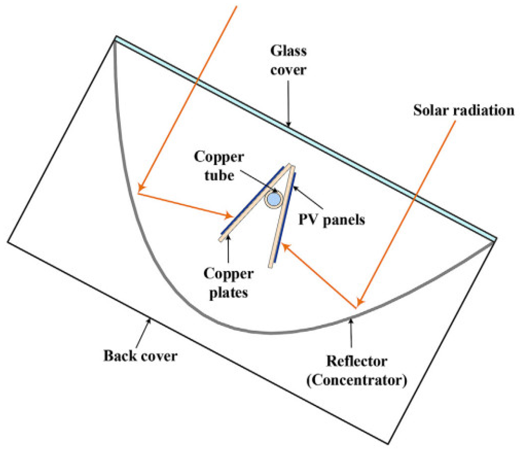
The study [86] proposed three variants of concentrator for the CPVT system: hyperbolic trumpet, V-trough, and compound parabolic. The silicon photovoltaic cells were placed on a copper plate with a circular duct for water flow, as shown in Figure 8. The solar radiation intensity was examined by 2D-Ray-tracing analysis, and then it was used to calculate the PV cell temperature. The results showed that the CPVT system in each case can generate almost the same amount of electricity with an efficiency ranging from 18.44% to 18.59%, but the hyperbolic trumpet requires twice the aperture as other reflectors, respectively.
The paper [87] evaluated the parabolic trough CPVT system equipped with multi-junction photovoltaic cells and water cooling. The heat receiver was in the form of a tube and worked under CR = 90. The experimental results that allowed to determine the maximum temperature of the PV cells in the CPVT system were lower than 100 °C, while the lack of cooling resulted in a temperature of approximately 130 °C. A single photovoltaic cell operated with 6 W of electric power. The maximum outlet fluid temperature was 87 °C. The dynamic model of the CPVT system combined with the thermal tank was prepared in the TRNSYSY software and described in [88]. The obtained results revealed that the system was capable of fully covering the heat demand of the residential user during the summer months, while an auxiliary boiler was necessary during the winter. The temperature in the thermal tank varied between 40–90 °C during summer and 28–56 °C during winter. The study [89] presents a feasibility study on the discussed CPVT system adopted for the house, the hotel, and the food industry. These applications would need 36, 1500 and 130,000 modules, respectively, and the discounted payback period was calculated as 5.6, 4.2 and 3.9 years.
A low-concentration (CR = 2) CPVT system was examined in [90,91]. A novel heat receiver, presented in Figure 9, was analyzed with a zero-dimensional thermal model, which was validated by comparison with experimental results. Maximum thermal and electrical efficiencies were 69.6% and 6.1%, respectively. The removal of the glass cover resulted in a reduction of optical losses, but thermal losses increased by 13%, which was not beneficial from a total efficiency point of view. Furthermore, the sensitivity to HTF inlet temperature was higher for the thermal part of the CPVT system than for the electrical part [90]. According to the results from [91], the location of the wedge receiver was sensitive to the angle of incidence and the maximum electrical efficiency equal to 8% was observed for 10°. The best measured thermal efficiency was 59.9%.
There are also designs of heat receivers in the form of circular ducts with inner fins to enhance heat transport. The performance of a parabolic trough CPVT system with CR = 37 was described in [92]. The aluminum receiver, known as CHAPS is presented in Figure 10. It consisted of a flat plate where monocrystalline photovoltaic cells were mounted and a circular tube with internal fins to enhance the heat transport rate. The experimental results showed average values of thermal and electrical efficiency in the CPVT system around 58% and 11%, respectively. Moreover, the authors studied the impact of the nonhomogeneous irradiation distribution on solar cells. It was found that the non-uniformities significantly influenced the electrical performance of PV cells along the receiver.
A similar design of the grooved tube receiver, shown in Figure 11, was also examined in [93,94]. The authors investigated the performance of a point-focus Fresnel lens CPVT system with triple-junction solar cells and CR = 1090. Conducted experiments showed that the highest photovoltaic and thermal efficiencies obtained at the same time were equal to 30% [93]. The results of outdoor tests presented in [94] revealed the highest electrical efficiency of 28% and a highest thermal efficiency of 54% with a water temperature of up to 55 °C. This research also developed a numerical model of the system based on the thermal resistance (ISFOC) method. The most important finding is that the electrical performance of the system and the temperature difference between the cell and the HTF depend linearly on direct irradiation.
According to the literature, a heat receiver with a circular duct for heat extraction is common in linear concentrating systems, especially with parabolics through the mirror. Other linear concentrators may be also used, such as hyperbolic trumpet, V-trough, and compound parabolic. Studies [93,94] showed that this kind of heat extraction device may even be used with point-focus systems—in this case, the circular duct is short and equipped with internal fins to enhance heat transfer.

3.3. Triangular Ducts

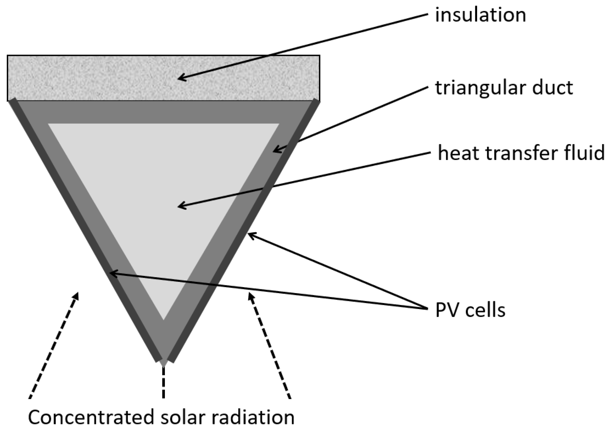
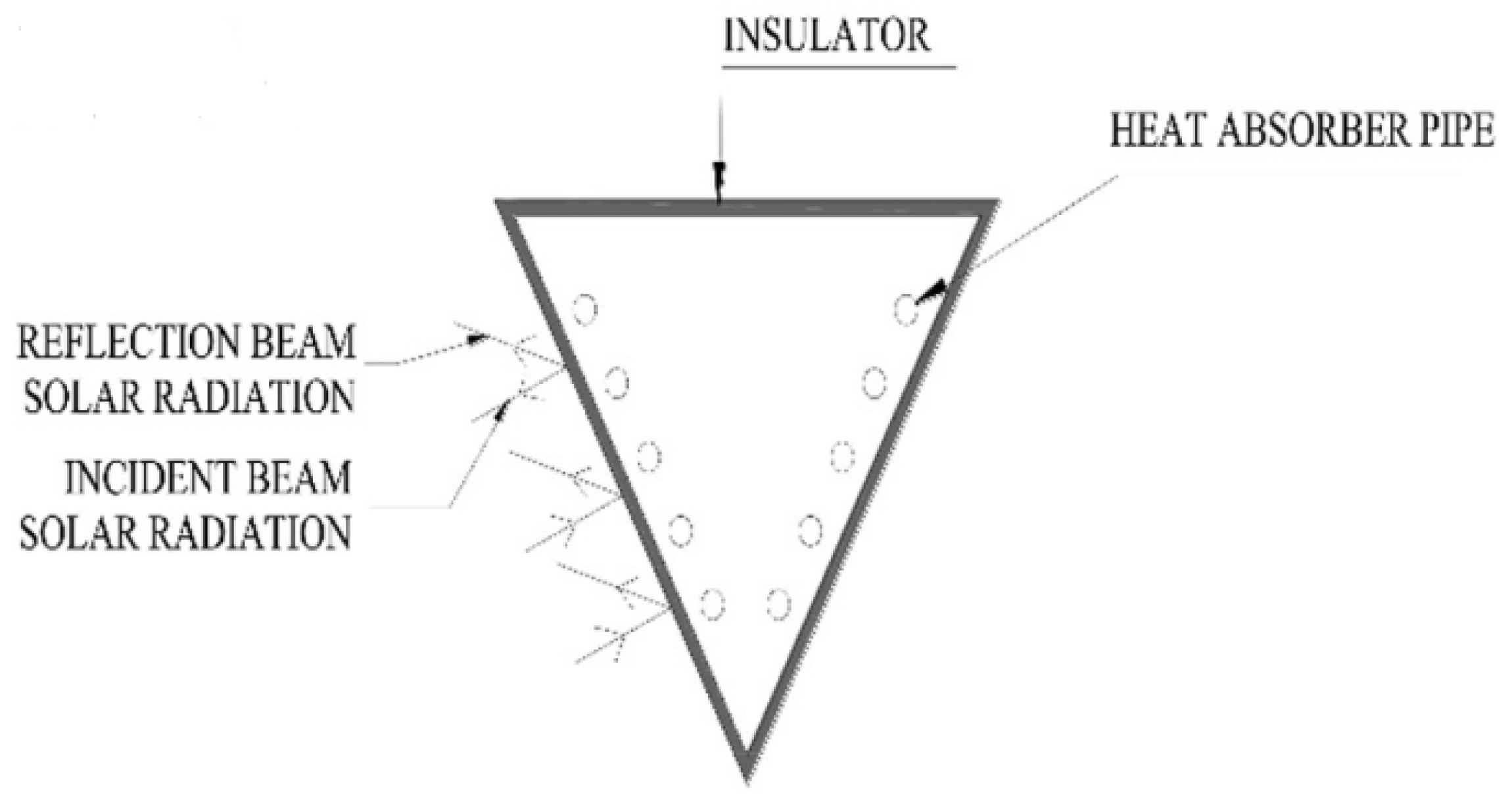
Another design of linear heat receivers includes triangular ducts, as shown in Figure 12. This shape, similarly to the rectangular channels, allows for mounting PV cells directly on the duct walls. According to the design, PV cells may be mounted on two walls, which collect the concentrated solar radiation, or even on three walls—in this case, cells located at the upper wall utilize non-concentrated solar radiation.
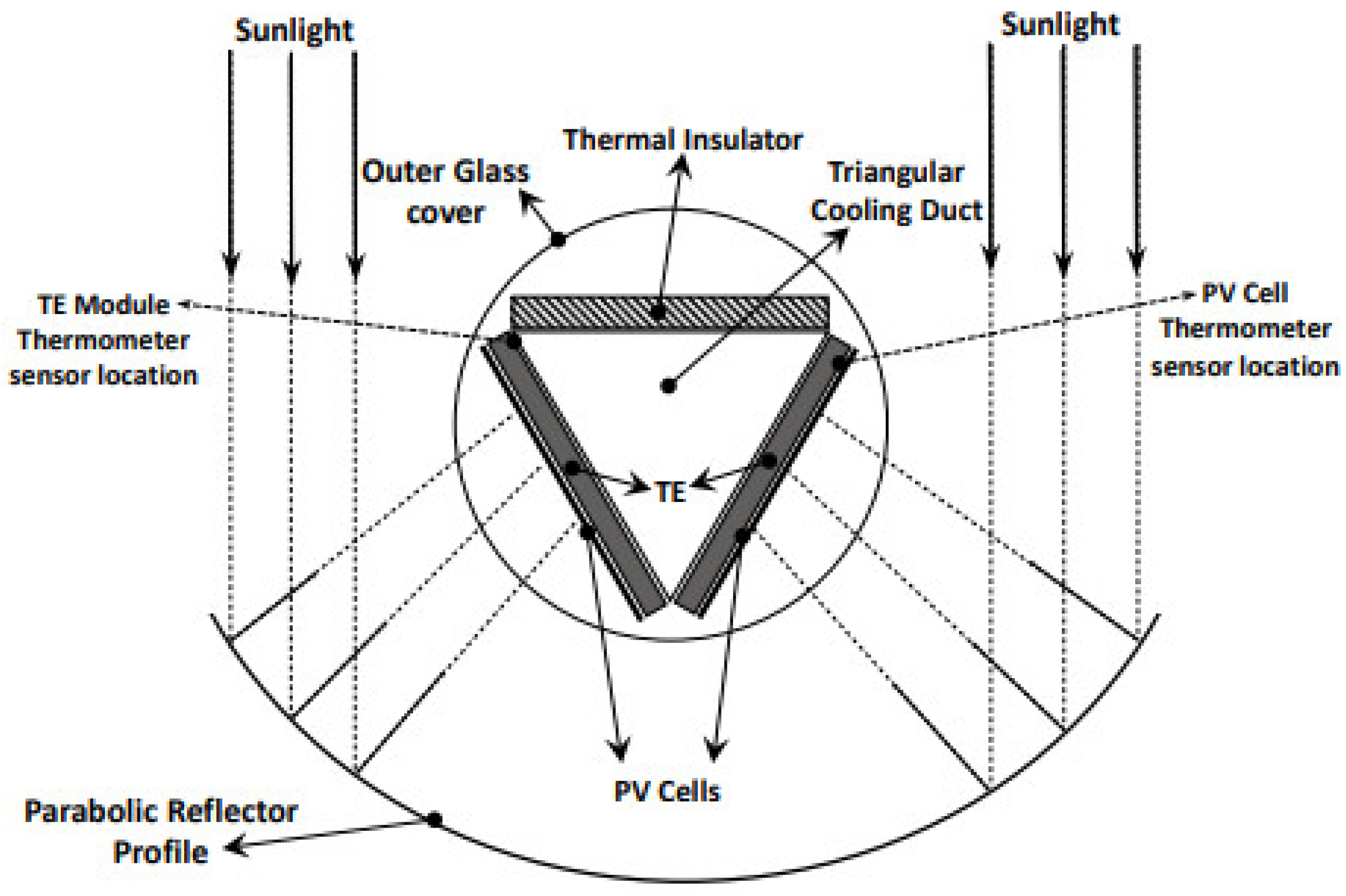
The studies described in [95] proposed a new receiver geometry for the parabolic trough CPVT system: a triangular channel with two walls covered with monocrystalline silicon cells and thermoelectric generators (TEG), whereas the third wall was insulated (see Figure 13). The construction tracked the Sun’s position along the N–S axis. The daily operation revealed an average electrical efficiency of 4.83% (0.16% for TEG and 4.67% for PV) and thermal efficiency of 46.16% for the system with a glass cover. After the glass cover was removed, the thermal efficiency dropped to 42.36%, whereas electrical performance was raised to 4.94% (0.12% TEG and 4.82% PV). The authors noticed the significant optical dissipations through the receiver, which caused the relatively low electrical efficiencies.
The CPVT system presented in [95] was also investigated numerically [96]. The authors provided a detailed three-dimensional computational model of a system that combined the finite volume (ANSYS fluent software) and Monte Carlo Ray-Tracing methods and was validated with experimental data. The results demonstrated the non-uniform distribution of concentrated solar radiation and high temperatures at the surface of PV cells. Further examination revealed the recommendations for the optimum system construction: reflector aperture width 1.6–2.2 m and apex angle 80°–120°.
Another triangular-duct receiver was investigated in [97]. Experimental measurements showed that the electrical efficiency of monocrystalline silicon cells under CR = 7.8 was only 6.4%. It was emphasized that low irradiation in Sweden leads to the low annual performance of the system. Moreover, the authors proposed a testing method for characterization, simulation, and evaluation of CPVT systems in different geographic locations.
Triangular receivers may also have a different shape of inner channels, as shown in Figure 14. The parabolic trough CPVT system examined in [98] was equipped with a triangular linear receiver that has a circular inner channel. In this case, two bottom walls were equipped with triple-junction cells, while the upper wall was not insulated but covered with absorbing material. The results showed a strong dependence between the system performance and incident irradiation. Furthermore, the insulation of the upper wall could increase electrical efficiency, simultaneously worsening the thermal performance.
Paper [42] investigated numerically the performance of a trigeneration system composed of a linear Fresnel CPVT unit and a 5 kW water-ammonia absorption chiller, located in Tehran, Iran. Two monocrystalline flat PV panels were placed on the prism-shaped receiver. The heat was collected by water-glycol solution flowing through 10 copper pipes (5 under each panel), as presented in Figure 15. Studies showed that the total efficiency of the CPVT system was about 71% (12.8% electrical and 58.0% thermal), whereas the efficiency of sorption cooling was 34%. TRNSYS software allowed for replacing the concentrating unit with a PVT panel. The results showed that the conventional collector was not able to generate enough energy to provide the normal operation of the chiller. The authors emphasized that the designed system could be employed as the heating and cooling source for residential buildings, but the electricity must be provided from the grid.
Comparative studies of a CT and CPVT system based on a parabolic trough mirror were described in [21]. The CT system used a circular tube as a receiver, whereas the second incorporated a triangular heat receiver covered in PV cells on two sides. The authors prepared both dynamic and stationary models in TRNSYS software and engineering equation solver (EES), respectively. The performance of the CPVT system was compared to the operation of CT installations located in an area with low, medium, and high solar irradiance. The results showed that the CT plant generates 11% more heat (107 MWh) than the CPVT system (100 MWh) and its initial cost is 16.5% lower. Nevertheless, the CPVT system generated 22 MWh of electricity for a one-year period with an average efficiency of 8% and its estimated decarbonization potential was 31% higher than for the CT system.
In summary, there are a wide variety of heat receivers in the form of triangular ducts. The presented designs vary in the shape of the triangle (equilateral or non), the shape of the internal channel (triangular, circular or set of parallel circular tubes) and the presence of insulation over the upper wall. The receiver may also be placed inside a glass tube to increase the thermal efficiency of the system.

3.4. Metal Block with Inner Channels

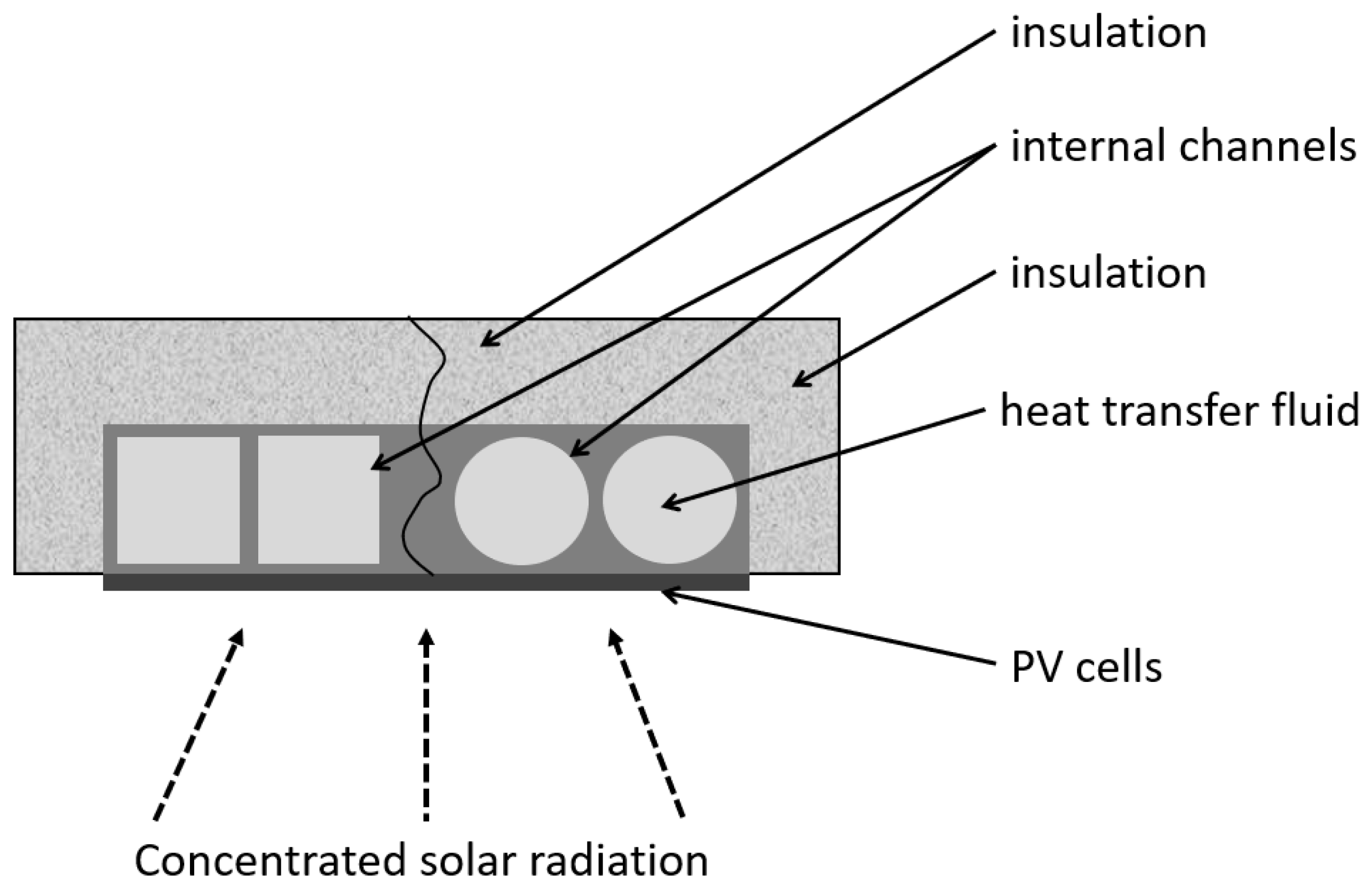
This subsection covers the design of heat receivers in form of a cuboidal block of metal, which has channels inside. According to the literature, these internal channels may have different cross-sections, such as: rectangles, square circles, ellipses, etc (see Figure 16). PV cells are mounted directly on the flat walls and the receiver may also be insulated.
A CPVT system described in [99] used a compound parabolic concentrator, but in this case, it was designed to eliminate multiple reflections of solar radiation. The heat receiver was in form of three parallel ducts with rectangular cross-sections, as shown in Figure 17. The authors experimentally tested two CPVT units. The first one with double-axis tracking and the second one with single-axis tracking (S–N). Obtained electrical efficiencies were 13% and 12%, respectively. Due to this insignificant difference in energy production, a large-scale system included only S–N tracking and achieved 55% thermal efficiency. The authors prepared two numerical thermal models of the system: steady-state and unsteady-state models to calculate the energy losses. Both showed good convergence with the experimental results. However, the stationary model was unable to predict rapid changes in system performance due to varying weather conditions.
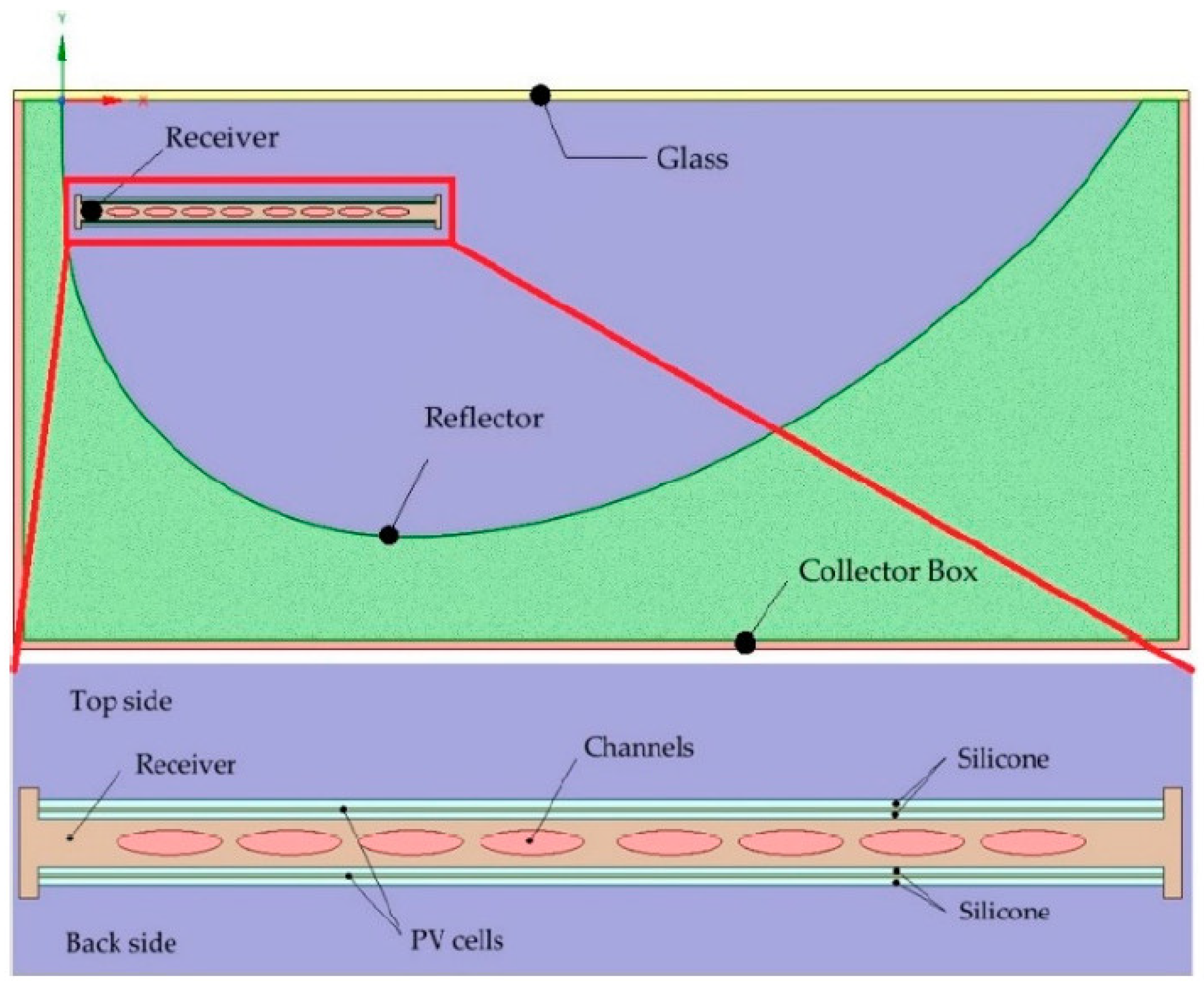
In [100], the thermal performance of a CPVT system with a novel concentrator geometry (see Figure 18) was studied under climate conditions for two distant countries: Sweden and Portugal. The authors developed a 2D and 3D numerical model to evaluate the temperature distribution in the PV panel and HTF temperature. The results revealed that the shape of the cooling channels in the heat receiver has an essential influence on CPVT performance. The hot spots were stronger for square and rectangle channels. The uniform distribution of temperature throughout the channel and the heat transfer ratio strongly depend on the internal area of the channels. Due to this, the largest surface contact was observed for the elliptical channels. The mentioned setup was also studied in [101] to assess the effect of tilt angle, HTF, insulation, receiver material, and front glass presence on overall system performance. The higher the temperature of the HTF, the lower the thermal and electrical efficiency. The stagnation temperature of the photovoltaic cells was 105 °C, which caused a decrease in electrical power by 32%. With appropriate mass flow, the temperature of the PV cell can decrease to 42 °C and cause an enhancement of electrical efficiency by 25%. Additional insulation on the back side of the reflector increased the thermal power by 3%, but the change of the material from aluminum to copper gave negligible effects. The idea of a CPVT system with custom-made receiver geometry was also studied in [72]. The authors compared the performance of this system working with water and nanofluids (Al2O3, TiO2, and SiC) as HTF. The results confirmed that the nanofluids may represent an appropriate alternative to water, but the erosion process might be intensified due to the pH of the nanofluid.
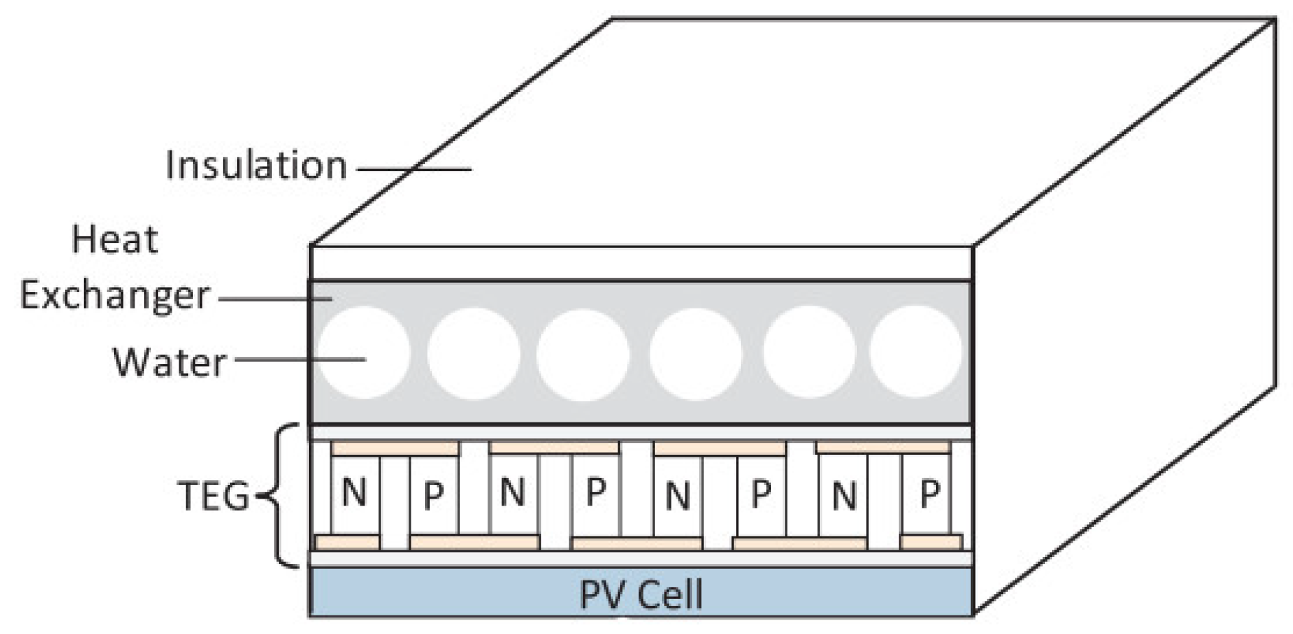
The combination of TEGs with parabolic CPVT systems was examined in [15]. The aluminum receiver included parallel circular channels arranged at an equal spacing throughout the receiver body, as shown in Figure 19. Outdoor experimental tests were carried out in the climate of Tunisia. The obtained results allowed to validate mathematical models. The authors highlighted that daily electrical efficiency can increase by 7.46% after the integration of TEGs, which corresponds to the additional 359 kWh of energy throughout the year.
A comparative study between the CPVT system and the CPVT integrated with TEG was conducted numerically and the results are presented in [102]. The receiver includes parallel elliptical channels arranged at equal spacing under the absorber plate, insulated, and filled with 0.5% graphene/water nanofluid. A transient study was carried out using London climatic conditions. The results showed that the use of nanofluid and TEG increased total electrical power compared to conventional CPVT by 9.77% on a summer day and by 4.58% on a winter day.
Presented studies revealed that the heat receivers in form of blocks of metal with internal channels find application in linear-focus CPVT systems. These devices were mainly insulated and some of them worked under the glass cover.

3.5. Serpentine Ducts

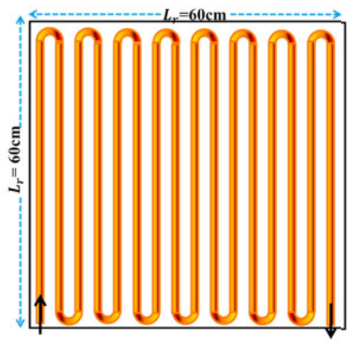
Serpentine ducts are one of the channel arrangements that can be found in conventional solar thermal collectors. This layout is characterized by sections of parallel channels that are connected with elbows. The photovoltaic cells may be mounted directly on the serpentine tube or on the absorber plate over the cooling circuit, as shown in Figure 20.
The most basic configuration includes two parallel channels connected by one elbow in the U-letter shape. The authors in [103] developed a small, linear, roof-integrated CPVT system with single-axis tracking. The receiver had an inner circular duct, which was bent in a U-shape (the inlet and outlet are on the same side of the receiver). The device’s capacity to generate useful energy under CR = 20 was investigated experimentally and numerically with ANSYS Fluent v14.5. The analyzed unit was characterized by 64% thermal efficiency, but the maximum outlet temperature was limited by the shape of the internal channel U-turn geometry. The authors concluded that a design with two separate channels could provide a higher outlet temperature, but simultaneously may lead to higher temperature gradients along the receiver.
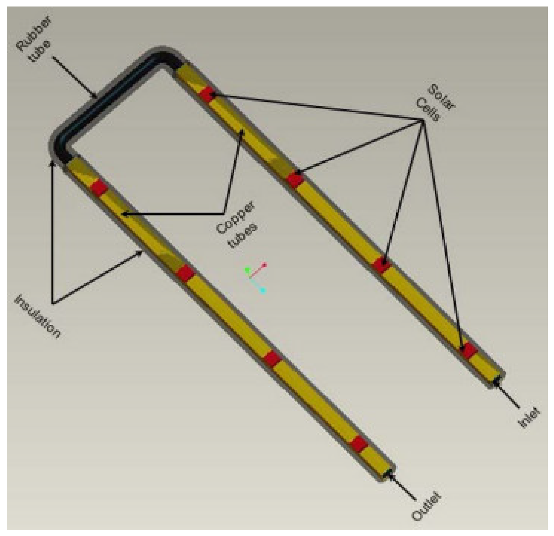
The paper [104] described numerical and experimental studies carried out for a U-shaped heat receiver installed in the CPVT system with Fresnel lenses. The receiver consisted of two parallel copper tubes that were connected together with a rubber tube, as shown in Figure 21. On each tube, four triple-junction solar cells were mounted. The authors studied numerically the influence of the HTF flow rate, ambient temperature, and solar irradiation on thermal and electrical outputs. The numerical results obtained from the ANSYS Fluent software were in good agreement with the experimental data. Presented studies demonstrated that the increase in the flow rate led to a decrease in the working fluid temperature and overall thermal power. On the other hand, the electrical power increased slightly. The optimum flow rate was found to be around 0.033 kg/s.
The CPVT system described in [105] was developed to experimentally examine the performance of PV cells under various operating conditions such as operating temperature, power production, and electrical efficiency. The heat receiver consisted of an aluminum plate with two parallel tubes underneath, connected to a flexible conduit. The parabolic trough reflector (CR = 8.5) allowed an increase in electricity production of approximately 4.7–5.2 times compared to the fixed cell. Furthermore, the water cooling in the CPVT system allowed to reduce the operating temperature of the photovoltaic system to 60 °C. The heat extraction from the photovoltaic cells saturated at a mass flow of around 0.03 kg/s.
Apart from these basic U-shaped serpentines, the cooling device may include numerous sections of parallel channels. The paper [106] discussed the effect of the number of internal channels in the heat receiver on the performance of the CPVT system. The authors considered two, three, four and six parallel channels connected at the ends by elbows in a serpentine arrangement. Generally, the thermal and electrical efficiencies increased with the number of channels.
The authors of [9] provided a theoretical model of a parabolic mirror CPVT system to evaluate its thermal and electrical performance in terms of irradiance and HTF temperatures. The triple-junction cells were actively cooled by a coil circuit and then harnessed thermal energy was used in the absorption heat pump cycle. The results allowed for selecting the best components and their size for the CPVT system under southern Italy’s working conditions to provide not only heat and electricity but also a condition for absorption heat pump operation. The same authors developed a model in ANSYS-CFX [107] to evaluate the potential energy generation from various configurations of the CPVT system. The cell efficiency for a sunny and a cloudy day was estimated at 28.9% and 23.2%, respectively. For beneficial weather conditions, the average cell temperature was 63 °C and the fluid temperature was 55 °C at the same time. Paper [108] provided a dynamic model of a coil circuit receiver (see Figure 22) coupled with triple-junction solar cells to estimate the outlet fluid temperature for a maximum cell operating temperature of 120 °C and for variable irradiance conditions. The results showed that the maximum temperature of the fluid with constant PV cell temperature is 75.4 °C, while for the beneficial conditions of high irradiance, the outlet temperatures varied between 60–75 °C for CR = 500 and were higher than 80 °C for CR = 1000.
The authors in [109] investigated the CPVT system with a parabolic dish. The receiver was made of squired-shaped tubes surrounded by the metallic substrate, as shown in Figure 23, and six different engine oil-based nanofluids flow through it. The authors found that the increase in the concentration of nanoparticles leads to an increase in energy efficiency and an increase in pressure drop.

3.6. Flow between Two Flat Plates

Another type of heat extraction device includes the flow of HTF between two flat plates, as shown in Figure 24. These plates may be made of metallic sheets or photovoltaic panels.
This kind of heat receiver was coupled with a triple-junction solar cell and a miniature concentrating parabolic dish (CR < 400) in [75]. Evaluation of system performance revealed 140–180 W of electricity production and 400–500 W of heat generation. Furthermore, this system was capable of generating high-temperature heat (200 °C) with a significant reduction in electrical efficiency.
Publications [8,110] experimentally and numerically examined a small-scale CPVT system with a parabolic dish. The heat receiver consisted of two photovoltaic panels—one collected the concentrated solar radiation, the second non-concentrated, and working fluid was flowing between these plates. According to the experimental results of [110], this water-cooling system enhanced electrical efficiency by about 2.5 times compared to the conventional photovoltaic system. A developed transient model allowed for simulating the effects of fluid flow and its initial temperature on the heat transfer in the heat receiver. The optimal design of the heat receiver required putting the inlet close to the upper PV panel and placing the outlet near the bottom panel. Ref. [8] investigated the influence of Al2O3 nanoparticle additions on the system performance by means of dimensionless analysis. The appropriate selection of particle sizes and concentrations could significantly improve overall system efficiency.
In summary, the extraction of heat via the flow of HTF between two flat plates is used in CPVT systems with a parabolic dish concentrator. The significant area of contact between the fluid and solid provides efficient cooling of PV cells.

3.7. Other Designs

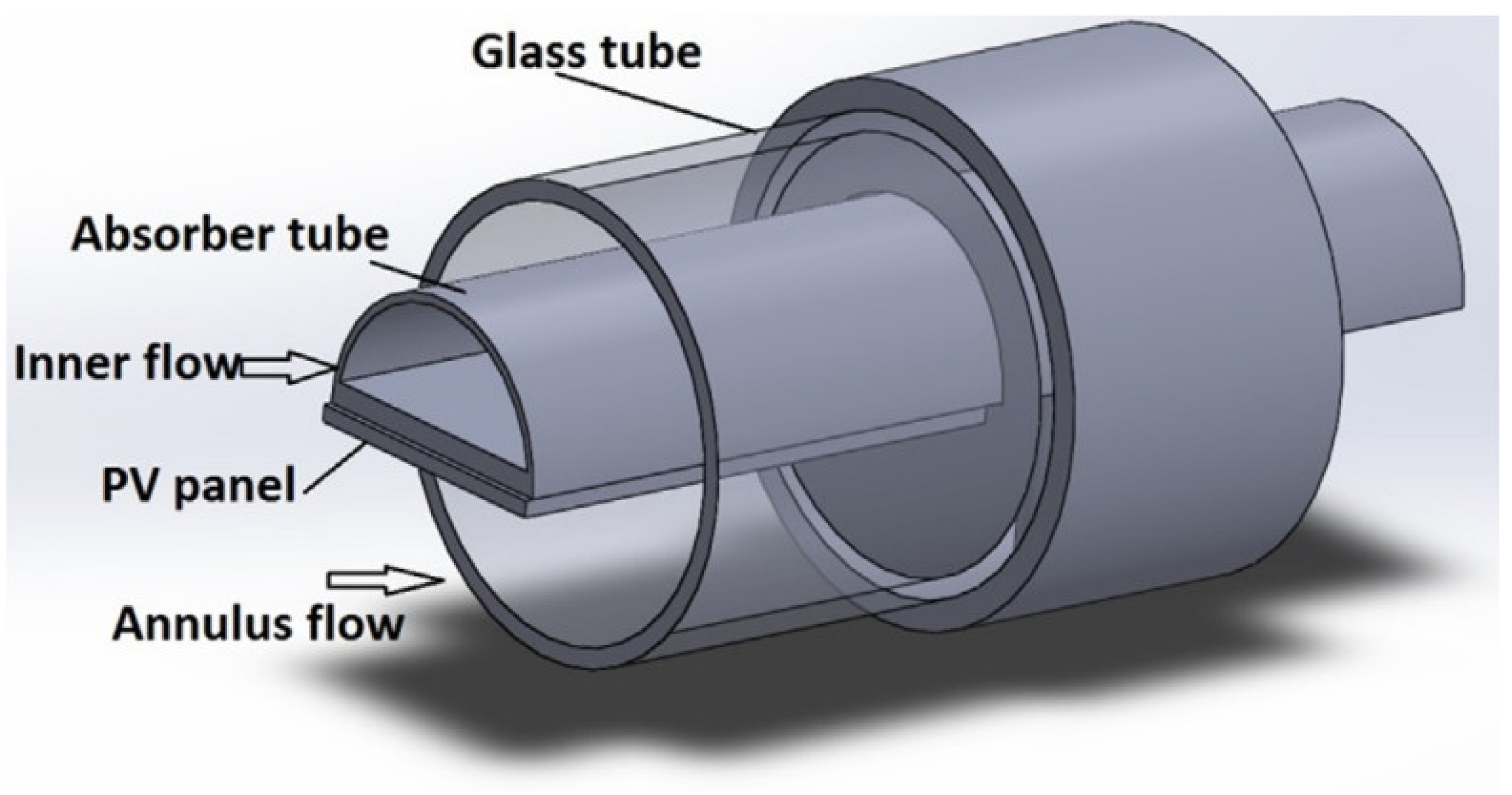
The literature review also showed some unique designs of heat extraction devices that could not be classified in the groups mentioned above. The work presented in [111] used a parabolic trough CPVT system. The authors proposed a cooling system with two separate flows. The receiver was made of a semi-cylindrical pipe and monocrystalline cells mounted on its flat surface. This construction was placed inside a glass tube and cooled by a second stream of water (see Figure 25). The theoretical model was developed and validated by comparison with experimental data from the experimental stand. The simulation results showed that cooling resulted in a drop in PV cell temperature from 80.8–88.9 °C to 69.7–75.0 °C and electrical efficiency in the range of 11.69–12.39%, depending on the flow rate in the system. The maximum value of the mean efficiency of the system was 61.42%, while the thermal efficiency was 49.48%. The maximum increase in the temperature of the HTF was noted as 28.7 °C. The optimal performance of the proposed system shows carbon mitigation of 40.2 tCO2/year.
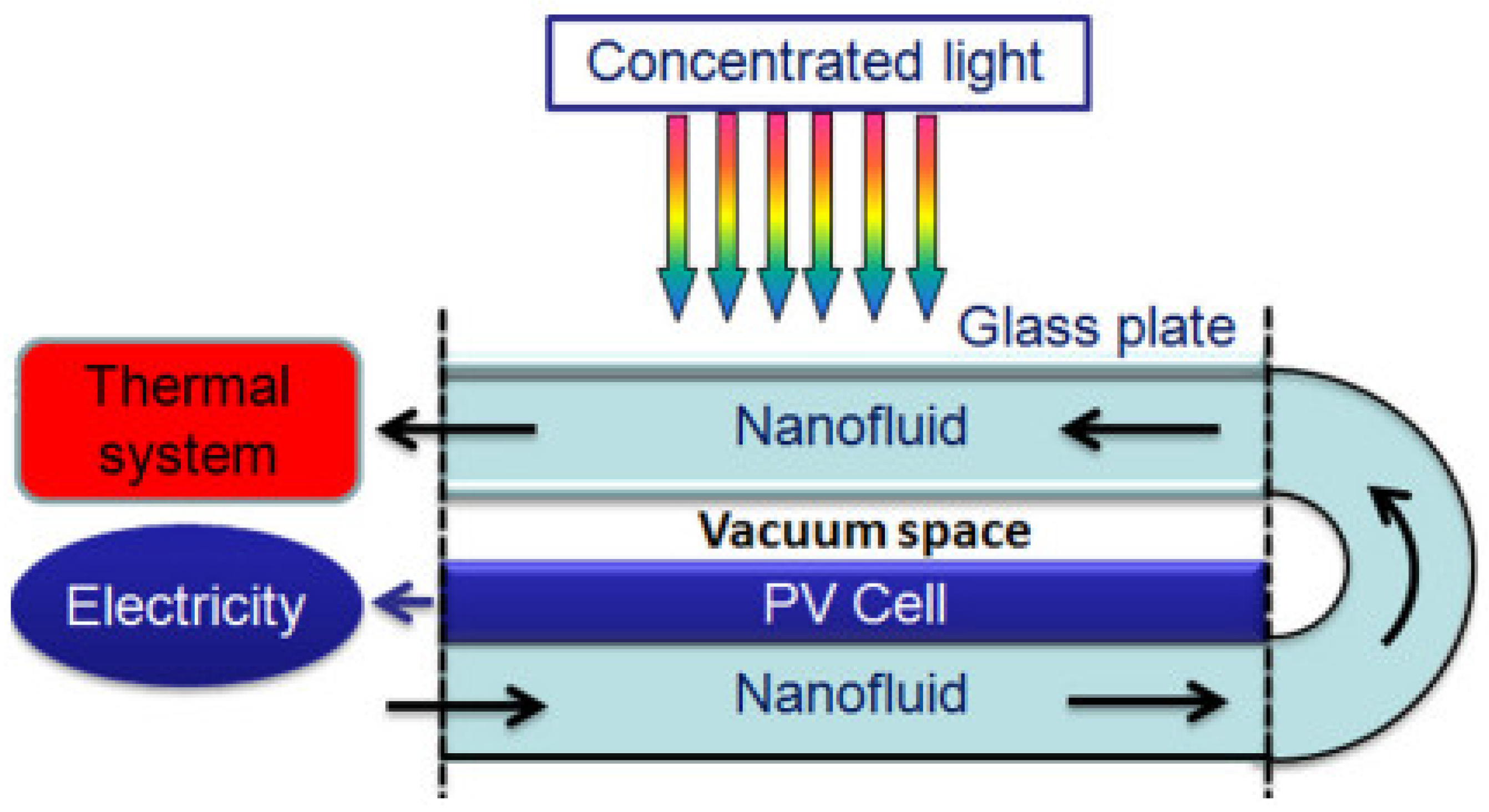
In the research in [112], a CPVT system was designed, which coupled pre- and post-illumination methods of cooling, as shown in Figure 26. Nanofluids with SiO2 particle sizes: 5, 10, 25 and 50 nm were used to enhance the thermal conductivity by up to 20%. The first layer of the nanofluid absorbed the infrared part of the spectrum, which could not be converted to electricity by the photovoltaic cell. The second layer flowed under the cell and extracted the heat directly from it. The system was reduced to a 2-dimensional CFD model to investigate exegetic efficiencies with various CR and nanofluid velocities. The results showed that nanofluids always enhanced the system performance. Furthermore, it was established that the highest exegetic efficiency was observed for CR = 40, where flow velocity was 0.015 m/s, while for CR = 100, flow velocity was 0.1 m/s.
Study [113] presented a novel solar cogeneration unit with a large Fresnel lens, where a semi-transparent CdTe solar cell used non-concentrated radiation and a spiral thermal receiver used concentrated sunlight. The authors experimentally examined system performance with the implementation of red and blue filters. The results show that the thermal and electrical efficiency of this system is higher for the red filter (65% and 3.4%, respectively) compared to the application of the blue filter (55% and 2.6%, respectively).
Parallel ducts connected with the header tubes at both ends are the most common arrangement used in conventional flat-plate heat collectors. As shown in the study [114], this pattern was also implemented in the CPVT system modeled in MATLAB. Irradiation was focused by a parabolic dish onto triple-junction cells, which were actively cooled. The heat was collected from head-riser tubes and stored in tanks. This heat management allowed for enhancing the total efficiency of the system by up to 85%. Furthermore, the design of the heat receiver was optimized using the frog leap algorithm, which resulted in an optimal spacing between the tubes equal to 6.34 cm.
Paper [115] presents a comparison between a commercially available PV panel with monocrystalline PV cells and the V-trough PVT system with CR = 2. Obtained results showed that the cooling device allowed to increase the PV power by 22.8% for conventional panels and by 31.5% for the V-trough CPVT.
The authors in [116] considered the possibility of upgrading an existing CT system into a CPVT installation. The numerical studies with the usage of Ray Tracing and Finite Volume methods allowed them to state that the existing heat receiver (cylinder with an M-shaped internal channel) was suitable for medium-temperature applications and its geometry should be modified to provide lower surface temperature to mount PV cells. This study also demonstrates the impact of non-uniform solar radiation on the thermal performance of the receiver.
Paper [117] investigated the performance of a parabolic trough linear CPVT system with CR = 130 operating in North Italy. The aluminum roll bond heat receiver was thermally connected with triple-junction PV cells and water was used as an HTF. According to the obtained results, this system was capable of producing medium-temperature heat (80–90 °C), which compensated for the decrease in electrical efficiency.
Table 4 presents a summary of all the discussed heat receivers with macro-scale channels. The table includes a short description of the analyzed device, its material, the name of the heat transfer fluid and the concentrator type (with CR) used in the research. Moreover, the type of PV cell and thermal, electrical and total efficiencies are summarized. Each study is also associated with its main findings.

4. Heat Extraction Devices with Microchannels

This section is devoted to the description of heat extraction devices with micro-scale channels dedicated to CPVT systems, which means that their dimensions are generally between 10 μm and 3 mm [94]. Microchannels are commonly used in the electronics industry to provide efficient cooling of processors and diodes, aerospace, and nuclear applications and their design is constantly being improved [121]. Microchannel cooling devices are characterized by a very high heat dissipation rate, so they also found an application in the field of CPVT systems. Microchannel devices generally work as heat sinks with passive cooling, nevertheless, in CPVT systems, they are incorporated into active cooling [22]. Microchannel devices are one of the most powerful technologies in the cooling of PV cells, but at the same time, they cause higher pressure losses due to additional wall shear-related pressure drop [71] compared to devices with macro-scale channels [67]. The compact size of microchannel-connected heat receivers makes them lightweight [22] and easy to manufacture using conventional machining. The microchannel cooling technique may be combined with jet impingement to improve the heat transfer ratio through increased fluid velocity [122].

4.1. Single-Layered Microchannel Devices

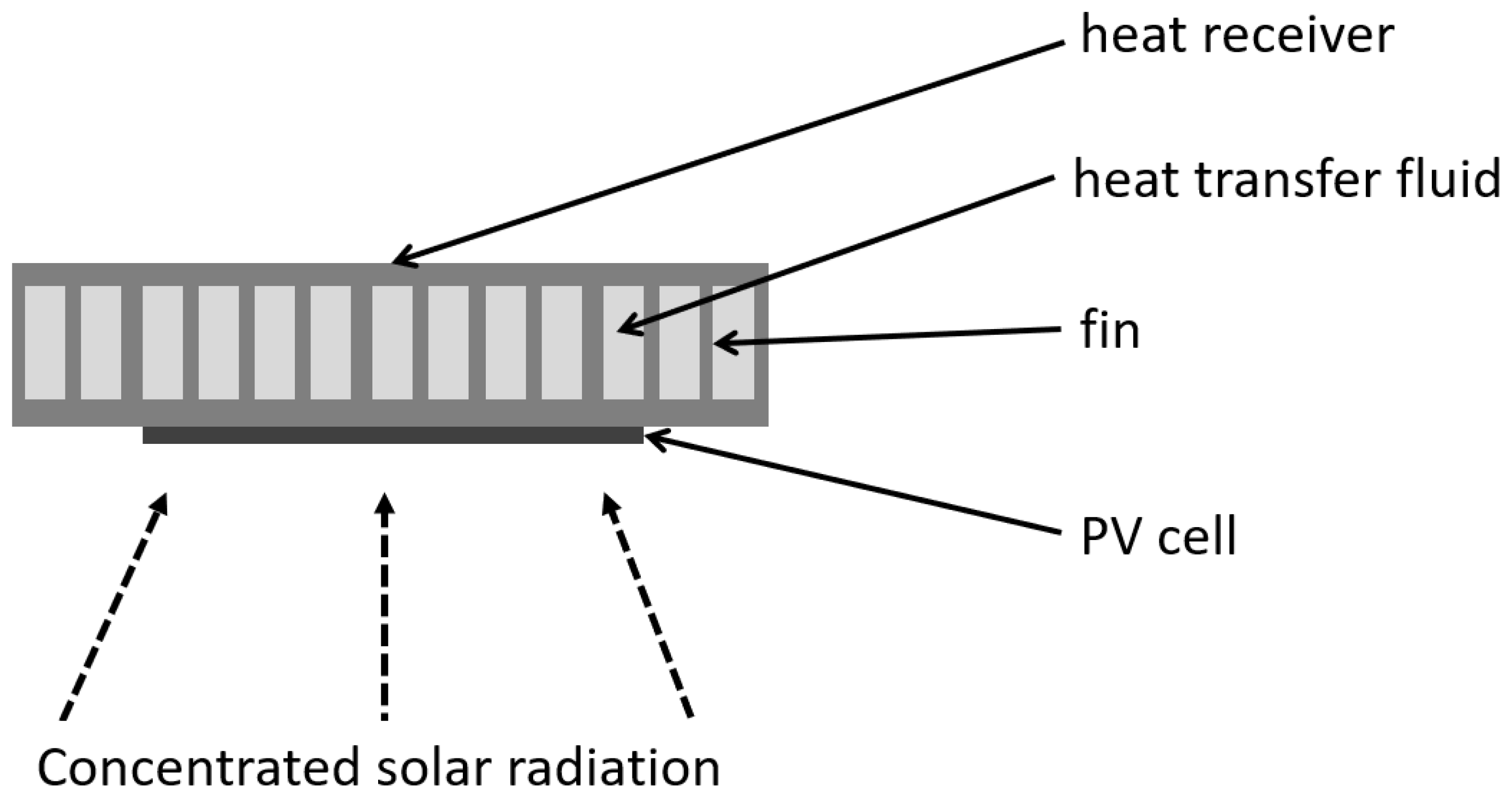
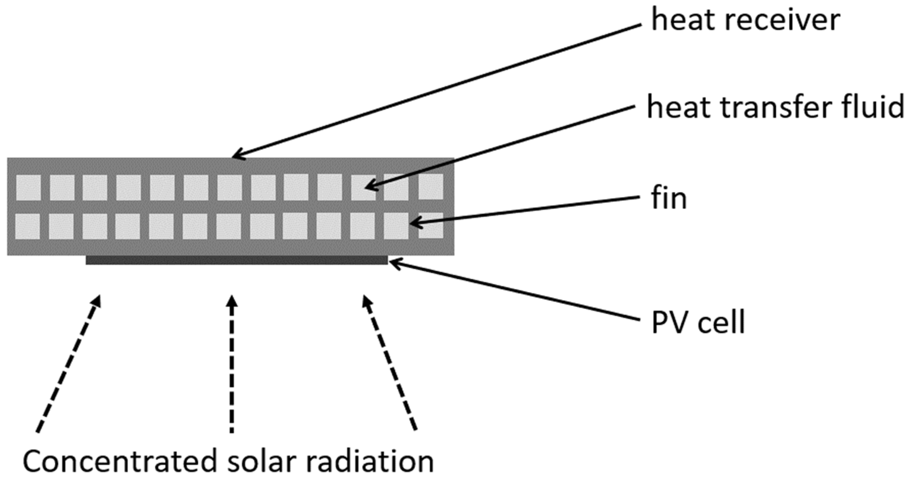
Heat receivers with a single-layer of microchannels represent the basic configuration, as shown in Figure 27. The thin fins create the same parallel channels for flowing HTF and simultaneously maximize the surface of heat transfer.
The authors of the study [123] presented, among others, a numerical model for a finned mini channel heat receiver. The results obtained indicated that the thin fins are desirable due to their beneficial impact on heat transfer and reduction of pumping power. In the case of water as an HTF, the addition of nanoparticles is beneficial, whereas the nanofluid based on oil worsened the hydraulic and electrical performance of the system. On the other hand, the application of oils allowed them to achieve higher outlet temperatures of the working fluid.
A single-layered microchannel immersed in flowing water was applied as a heat receiver in Fresnel lens CPVT system integrated with TEGs [124]. The authors studied the multi-junction solar cells and laser-grooved buried contact (LGBC) silicon cells connected to the two TEGs with 127 and 271 junctions. The results showed that the TEGs allowed for enhancing the overall power production, but the PV cells performed better when attached directly to the heat sink.
The authors in paper [98] modified a polycrystalline silicon cell structure to enhance heat dissipation in the microchannel heat sink by changing materials below the silicon wafer. The impact of the introduced changes was estimated based on the 3D numerical model validated with the available experimental, numerical and analytical data. It was stated that for CR < 3.5, the cooling of PV cells is not necessary, whereas for CR = 20 PV cells required integration with a microchannel heat sink. The higher the concentration ratio, the higher the reduction in operating temperature of the modified cell compared to the basic design. In the optimal case, with an HTF flow rate of 100 g/min, the temperatures of the modified and conventional cells were 66 °C and 108 °C, respectively. The CPVT system with the novel cell worked with 17.5% electrical efficiency and 70.8% thermal efficiency. These parameters for conventional cells were lower: 13.5% and 69%, respectively.
The effectiveness of heat transfer depends on the geometrical parameters of the microchannels: the thickness and height of the fins and the spacing between them. Study [125] investigated an ultrahigh CPVT system (CR = 1800 suns). The construction included a two-stage concentrator: a non-imaging dish concentrator and an array of compound parabolic lenses. The authors optimized the design of the heat sink (see Figure 28) to provide a temperature below 100 °C on the PV cell. The ray-tracing method was used to determine the irradiance distribution over the absorber surface and the results obtained were implemented as a boundary condition to the CFD model. Variant analysis included various fin thicknesses (1, 2 mm), fin heights (5, 10, 15, 20 and 25 mm) and water velocities (0.6, 0.8, 1.0 m/s). The results revealed that the configuration with fins 1mm thick and 20mm high provided the lowest average temperature of PV cells and the most uniform distribution of this parameter. This design, accompanied by a coolant velocity of 0.6 m/s, allowed for the maintenance of a cell’s temperature at 91.4 °C, at a direct normal irradiance of 1000 W/m2. Thanks to the efficient heat extraction, the system was operating with electrical efficiency of 31.8%.
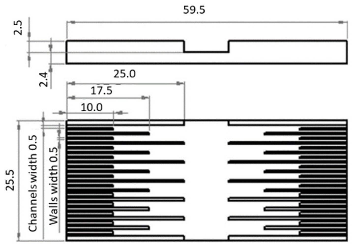
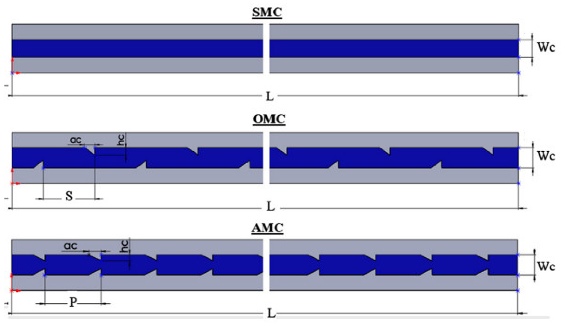
Another approach to optimize the performance of microchannel heat receivers included the variable width of channels (i.e., spacing between fins) in different parts of the device: close to the inlet, middle part, and close to the outlet. A prototype full-scale parabolic trough CPVT system was evaluated in [28]. The optical element was examined through experimental measurements and ray-tracing simulations, and it was estimated that the total optical efficiency is very low at about 50%. Then, two variants of the elongated plate-fin heat sinks were evaluated, i.e., with constant or stepwise varying width, as shown in Figure 29. The second was shown to significantly reduce pumping power. This prototype CPVT system was found to achieve an overall efficiency of approximately equal to 50% (44% thermal and 6% electrical efficiencies).
The authors of [28] conducted another numerical and experimental study on heat sinks with varying microchannel widths [126]. The heat sink was connected to the inlet and outlet manifolds and HTF flows were examined in the range of 20–40 g/s. A 3D numerical model was prepared to investigate the flow development. The results showed that in the cases analyzed, the pressure drop was always lower than 1000 Pa and was induced mainly in the densest section of the heat sink. In contrast, in the section with the widest spacing between the fins, the buoyancy had a beneficial impact on thermal performance, regardless of the flow rate of the HTF. Moreover, the heat transfer rate was enhanced by vortices generated in the microchannel structure. The authors showed that the flow characterized by a low Reynolds number provides a more homogeneous distribution of the temperature on the wall of the heat sink. A dynamic, theoretical model for the prediction of the long-term performance of a CPVT system was discussed in [127]. On the basis of the results, it was concluded that enhancement of thermal and electrical output could be achieved with a low flow rate and elevated fluid inlet temperature.
Paper [128] numerically examined four different designs of a stepwise varying width microchannel with rectangular internal fins under CR = 1000 suns. The authors concluded that the internal geometry of the receiver and the mass flow of HTF determine the cell temperature, electrical and thermal efficiency, total exergy efficiency, and thermal resistance. An increase in coolant flow rate by 40 times allowed for the reduction in the cell temperature by more than 30 °C and simultaneously reduced the temperature non-uniformity from 15.5 °C to 9 °C. Generally, at higher flow rates and increased numbers and lengths of internal fins, the thermal resistance was reduced, whereas the pressure drop was increased.
In [65], a novel heat receiver with a varying width of microchannels was proposed, as shown in Figure 30. This device combined microchannel technology with jet impingement cooling. The performance of this hybrid system was experimentally tested for double optics, CR = 537 suns, and a dummy cell mounted on the receiver surface. The results proved that this design was suitable for CPVT applications due to the low thermal resistance (up to 6.2 × 10⁻⁵ K m2/W) and the temperature uniformity (0.7 °C).
Another hybrid jet impingement/microchannel heat receiver was studied in [129]. In ANSYS Fluent the authors examined five new designs coupled with triple-junction solar cells and a concentrating system with CR = 1000. The proposed designs were characterized by the location of the inlet in the central part of the receiver. It resulted in a reduction of the maximum PV cell temperature to 55 °C and an enhancement of the electrical efficiency to 39.7%. Overall, energy efficiency of 53.5% was also obtained.
A similar concept to the varying width of microchannels with a constant thickness of fins is a configuration with various thicknesses of fins. Tree-shaped channels were proposed in [130] and analyzed against the conventional heat sink with parallel and equal fins. The results revealed that the novel geometry allowed for a reduction in the maximum temperature of the PV cells of about 10 °C. Moreover, the temperature distribution over the receiver absorber was more homogeneous and the thermal stresses were significantly reduced.
Generally, there are known other studies that investigated the efficiency of microchannels with various cross sections: hexagonal, circular, rhombus [131], trapezium, and two concave/convex surfaces [132]. Nevertheless, these studies have not been dedicated directly to CPVT systems, therefore they are not presented in this paper extensively.

4.2. Multi-Layered Microchannel Devices

In addition to single-layer microchannel devices, there are also known multi-layered heat receivers, which are considered more efficient in terms of heat transfer [66]. The concept of a multi-layered heat sink was first examined in paper [133] in the case of electronic cooling. However, it was quickly adapted for application in CPVT systems. The main drawback of the multi-layered concept is the significant increase in pressure drop, therefore the design should balance thermal and hydraulic performance. The exemplary cross-section through a double-layered heat sink is shown in Figure 31.
The study [134] investigated the performance of an MJ solar cell combined with a multi-layered microchannel heat sink in both indoor and outdoor operating conditions. Indoor studies showed that the more layers in the heat sink, the better electrical efficiency of the tested solar cell: for the three-layered heat sink shown in Figure 32, the power increased by 9.4% and the surface temperature was reduced by 3.15 °C compared to the single-layered geometry. The experiments conducted outdoors allowed for determining the maximum electrical power of 4.59 W and the thermal power of 12.85 W with a solar cell temperature below 61 °C. The study [66] showed that the application of four layers reduced the temperature from 88.6 to 73.6 °C under an extreme heating load of 30 W/cm2. Moreover, the receiver with one layer of microchannels was characterized by the highest non-uniformity of the temperature distribution.
The authors in [135] conducted a numerical study in ANSYS FLUENT 17.2 of the three-dimensional model of a microchannel heat sink integrated with polycrystalline silicon PV cells. Five various configurations of microchannel were considered: a wide rectangular microchannel, a single-layer parallel- and counter-flow microchannel, and a double-layer parallel- and counter-flow microchannel. Each design was studied in various operating conditions to determine the distribution of temperature at the surface of the solar cell. The results for CR = 20 showed that the heat sink with the single-layer parallel-flow microchannel configuration provides the best operating parameters for PV cell operation, while a single-layer counter-flow microchannel heat sink is the least effective design. The reliability of the model was confirmed by validation using available experimental and numerical data.
In summary, the optimum number of layers strongly depends on the operating conditions. Moreover, apart from the number of layers, the flow direction: counter- or parallel may play a significant role in the cooling process. Generally, the study [136] compared the performance of six heat sinks with different numbers of layers—from one to six. The results showed that the optimum number of layers was found to be three.

4.3. Microchannel with Internal Features

The enhancement of heat transfer via the extension of the solid–fluid contact area may be performed not only by an increase in the number of microchannel layers but also by the introduction of internal features. Moreover, these obstacles also change the pattern of flow. Such a study can be found in [137]. It numerically examined (in COMSOL Multiphysics 5.1 software) a microchannel heat sink dedicated to a CPVT system with CR = 1000. The authors introduced additional features on the inner walls of the microchannels to enhance heat transfer. The proposed design included a triangular forward mounted in aligned and offset distributions, as shown in Figure 33. Based on the results, these modifications are viable only for laminar flows with Re < 200 because higher velocities lead to a significant increase in pumping power.

4.4. Microchannel with Pin Fins

The conventional microchannel uses parallel fins, which create rectangular cross-sections. However, there are also designs that include different shapes of internal obstacles, such as: cylinders, cones, etc., which may create different patterns.
Four geometries of pin-finned microchannel heat sinks (in-line cylindrical, staggered cylindrical, inline conical, and staggered conical) were numerically analyzed in [30]. These geometries were dedicated to the Fresnel CPVT system with CR between 500 and 2500, which used a multi-junction PV cell. Based on the results it was stated that the highest total efficiency 80.20% was noted for geometry with in-line conical pin fins. Generally, cylindrical-shaped pin fins could provide efficient cooling for CR < 2500, while conical-shaped pin fins worked correctly for CR < 2000, but provided a higher outlet temperature of HTF. Moreover, the in-line pin fin configuration improved the temperature uniformity in the PV cell compared to the staggered arrangement.
Microchannel with round pin-fins dedicated to CPVT system with CR = 500 was investigated in [138] and its performance was compared to the heat sink with straight fins. The results showed that the water cooling maintained the maximum temperature of PV cells under the 80 °C limit. Generally, the heat sink with straight fins showed better thermal performance than the heat sink with round pins.

4.5. Other Designs

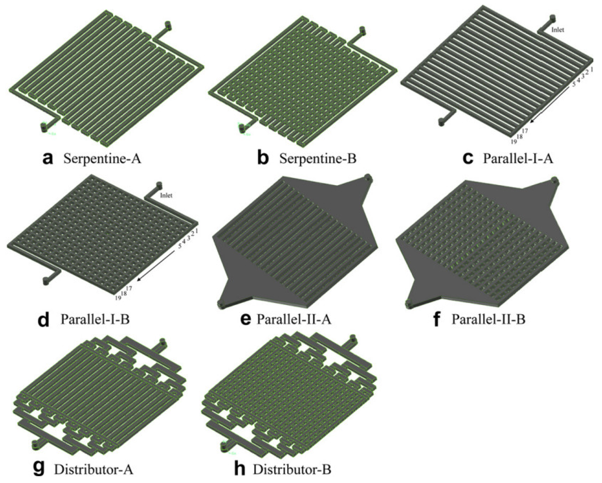
The conventional and novel designs of microchannel heat sinks with liquid cooling were numerically studied in [139]. These channel configurations included serpentine, parallel, parallel with manifolds, and distributor (each type with and without transverse slots), presented in Figure 34. The authors used ANSYS Fluent to analyze heat transfer performance and pressure drop for each design under a laminar flow regime. The results showed that the novel distributor-like configurations are promising for application in CPVT due to excellent flow and temperature uniformity.
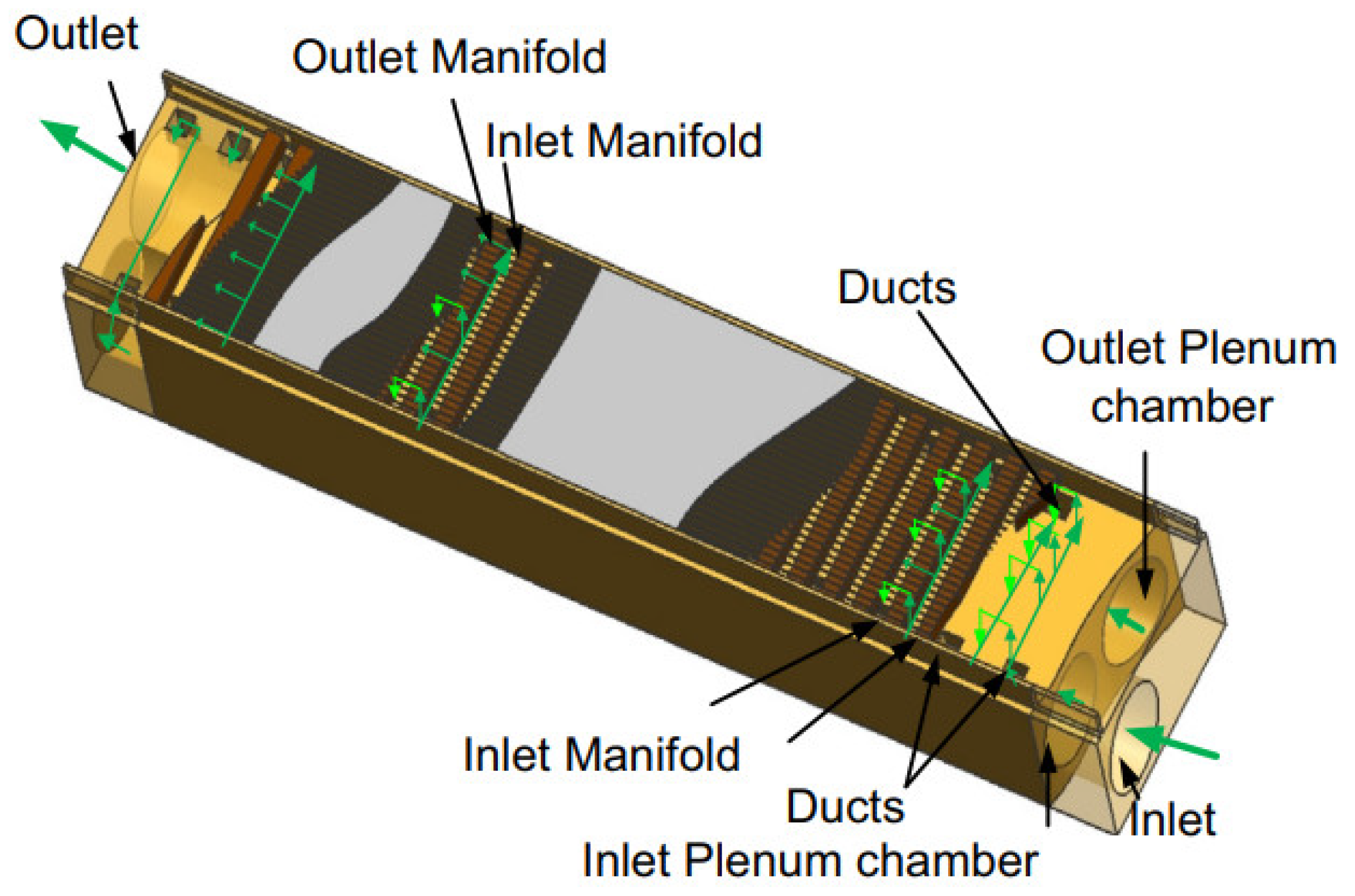
The study [140] presented a novel geometry of a multi-layer heat extraction device, consisting of 41 parallel microchannels below PV cells, inlet and outlet manifolds in the middle, and a plenum chamber at the bottom (see Figure 35). Analyzed geometry of the heat receiver allowed for a reduction in the temperature difference over the PV cells below 6.3 °C and for minimizing the total pressure drop to 3000 Pa.
In the study [141] a parabolic CPVT system coupled with a heat pump was evaluated. The heat receiver was in the form of a rectangular porous channel with Al2O3 HTF. The optimal mass flow rate was optimized from the thermo-economical point of view. The results showed that the increase in mass flow leads to a lower temperature of both PV cells and HTF at the outlet and the optimal performance is achieved for a mass flow of 0.01382 kg/s. According to the results, the maximum performance of the heat receiver was obtained for 95% porosity.
Paper [142] examined a CPVT system based on point-focus Fresnel lens and MJ cells. Both experimental and numerical studies were carried out at different flow rates of HTF. The results revealed that the total, thermal and electrical efficiencies achieved during the experiment and simulation were, respectively: 68.7%, 49.5%, 36.5% and 73.5%, 55.4%, 37.1%. The model gave higher values as a result of the heat losses associated with the experimental tests. Depending on the HTF flow rate, the elevated cell temperature varied between 21 °C and 38.3 °C, whereas the HTF temperature increase was between 0.25 °C and 14.75 °C.
Table 5 presents a summary of all discussed heat receivers with micro-scale channels. The table includes a short description of the analyzed device, its material, the name of the heat transfer fluid, and the concentrator type (with CR) used in the research. Moreover, the type of photovoltaic cell and thermal, electrical, and total efficiencies are summarized. Each study is also associated with its main findings.

5. Summary

Liquid-cooled heat extraction devices are commonly used to enhance the conversion efficiency of CPVT systems as a result of their reliability and high effectiveness compared to other cooling methods and solutions. The main aim of the cooling device is to provide a low and homogeneous temperature of the PV cell, generate heat characterized by reasonably high temperatures, and simultaneously minimize the parasitic load. The extracted thermal energy may be utilized in various applications depending on the temperature of the heat transfer fluid. Possible applications include district heating, domestic heat water preparation, drying, air conditioning, absorption cooling, desalination, organic Rankine cycles, etc. The major part of the published research papers focuses on the overall performance of the concentrating systems, and there are some reviews on this topic as well. However, there is no detailed review in the field of geometry designs of heat receivers dedicated to CPVT systems. The various heat extraction methods are comprehensively reviewed in this paper to discuss the current state-of-the-art, limitations, and possibilities of the presented designs. There is a wide range of designs of heat extraction devices dedicated to CPVT systems. Due to this, the analyzed devices were classified into two main categories: heat receivers with macro- and micro-scale channels. Each heat receiver geometry was juxtaposed with the corresponding concentrating element, photovoltaic cell, concentration ratio, heat transfer fluid, and operating parameters of the specified system.
The simplest form of a receiver for a CPVT system with a linear concentrator is a long duct that may have a cross-section in the shape of a rectangle, circle, or triangle. Due to the simple construction, the receiver may be considered leakproof. Moreover, the relatively wide aperture area allows them to be used in systems with low-precision tracking or even in stationary roof-integrated applications. PV cells may be mounted directly on the selected flat surfaces to collect both concentrated and non-concentrated solar irradiation. Other walls can be insulated or treated as an absorber. The efficiency of cooling strongly depends on the area and quality of thermal contact between the photovoltaic cell, receiver, and working fluid. In some cases, the shape of the internal channel (or channels) was different from the outer shape. Heat receivers in the form of cuboidal blocks of metal with channels inside may also have various internal cross-sections, such as: rectangles, square circles, and ellipses. It was shown that this shape directly influences the performance of the CPVT system by the presence of hot spots and stagnation zones. The geometries of serpentine ducts include sections of parallel channels that are connected to elbows. Photovoltaic cells may be mounted directly on the serpentine tube or indirectly on the absorber plate over the cooling circuit. In the case of a U-shaped receiver, it was found that two separate channels could provide a higher outlet temperature, but simultaneously may lead to higher temperature gradients along the receiver. Generally, thermal and electrical efficiencies increased with the number of channels located under the common absorber. Another design included the flow of HTF between two flat plates, providing a significant area of contact between the fluid and solid, and therefore the efficient cooling of PV cells. The novel geometries of heat receivers included a semicylindrical pipe with cells mounted on its flat surface, enclosed in a glass tube or system with coupled pre-and post-illumination cooling methods. The proposed solutions are mainly prototypes, which means that they are not optimized and not prepared for mass production. Among heat receivers with macroscale channels, the most popular HTF is water with a 75% share (see Figure 36a). Nanofluids are almost twice as popular as water–glycol solutions. The least common HTF is thermal oil, used only in 2% of the analyzed papers. Regarding the receiver material (Figure 36b), the most common is aluminum (42%) followed by copper (29%). Other materials such as steel or glass were used only in 2% of all cases.
In the case of heat extraction devices with microchannels, the heat dissipation rate is very high, making it one of the most efficient technologies in the cooling of photovoltaic cells, which may even be combined with jet impingement to enhance the heat transfer ratio. However, the size of the internal channels leads to an additional wall-shear-related pressure drop, which is higher when the internal fins are packed more densely. A single-layer of microchannels represents the basic configuration of this device. The effectiveness of heat transfer depends on geometric parameters such as the thickness and height of the fins and the spacing between them. Generally, at higher flow rates and increasing the number and length of internal fins, the thermal resistance is reduced whereas the pressure drop increases. The channels may also be characterized by a variable width in different parts of the device, significantly reducing pumping power. In the case of wide-spaced fins, the buoyancy has a beneficial impact on thermal performance. A similar concept to the varying width of microchannels with a constant thickness of fins is a configuration with various thicknesses of fins—this geometry allows for a reduction in the temperature gradient over the PV cell. Another concept includes multi-layered heat receivers, which are considered more efficient in terms of heat transfer and provide a more homogeneous temperature distribution. The optimum number of layers strongly depends on the specification of other elements in the system, and some studies showed that the optimum number of layers is three. The microchannels may also have different cross sections such as hexagon, circle, rhomb, trapezium, etc. Apart from the channel numbers and shape, the flow direction: counter or parallel, may play a significant role in the cooling process. Moreover, the enhancement of heat transfer via expansion of the solid-fluid contact area may be achieved by introducing internal features. These modifications are viable only for laminar flows with Re < 200 because higher velocities cause a significant increase in pumping power. Microchannel cooling devices may also include designs with different shapes of internal obstacles, such as: cylinders, cones, etc. Generally, cylindrical-shaped pin fins could provide efficient cooling for CR < 2500, whereas conical-shaped pin fins worked properly for CR < 2000, but provided a higher outlet temperature of HTF. Moreover, the in-line pin fins configuration improved the temperature uniformity on the PV cell compared to the staggered arrangement. Novel microchannel configuration geometries are also proposed, including serpentine design, parallel or parallel with manifolds (each type with and without transverse slots). Among them, the distributor configurations provided excellent uniformity of flow and temperature. In the case of heat receivers with micro-scale channels, only two HTF were used (see Figure 37a) in the analyzed papers, i.e., water with a 90% share and nanofluids with the remaining 10% share. Regarding the receiver material (Figure 37b), more than half (57%) of the receivers were made of aluminum. The second most popular material was copper with a 14% share. Other materials such as steel or silicon were used in 10% of the analyzed cases.
A comparison of the selected aspects of heat extraction devices with micro- and macroscale channels is provided in Table 6.
Figure 38 summarizes the share of individual geometry designs of heat receivers in the case of heat extraction devices with macro- and microscale channels. In the first case, the most popular design includes ducts with a circular cross-section (25%), which are followed by linear ducts with a rectangular shape (15%) and receivers with serpentine-shaped channels (15%). Slightly less popular designs include triangular ducts and metal blocks with internal channels (both with a 13% share). Regarding the microchannel devices, half of the analyzed papers are focused on single-layered receivers. Multi-layered geometries take an 18% share. Designs with pin fins (9%) and internal features (5%) are less popular. There is also a significant group (18%) of alternative designs which has not been categorized.
Generally, it is problematic to compare the efficiency of all discussed designs because different studies investigated various operating parameters, such as thermal and electrical power, pressure loss, energy and exergy efficiency, etc. Moreover, the investigated devices were manufactured from different materials, used various heat transfer fluids and cooperated with different types of PV cells and concentrators. Some of the analyzed papers have not given information about all mentioned aspects Therefore, it is not possible to point to the best design, but general recommendations regarding the design may be provided:
  • The design of the heat extraction device in a CPVT system should be adjusted to the particular thermal and electrical requirements;
  • Microchannel heat receivers should be used when high heat dissipation is required, which means CPVT systems with high and ultra-high concentration ratios;
  • The thinner the fins in the microchannels are, the more efficient the heat transfer and the higher pressure losses;
  • Internal features may be introduced to microchannels, but they require a low velocity of HTF;
  • Heat extraction devices equipped with macro-scale channels are suitable for CPVT systems with low- and medium concentration ratios;
  • The length of the linear heat receiver should be adjusted to the required outlet temperature of the HTF, taking into consideration a temperature gradient along the receiver, which leads to mechanical stress over the receiver body;
  • Straight macrochannels provide the lowest pressure drop;
  • Rectangular channels are accompanied by hot spots and stagnation zones close to the right angles, contrary to the macrochannels with a circular or elliptical cross-section.
  • An increase in the area of heat transfer in macro-scale channels may be provided by the application of internal features such as ribs, fins, etc. Caution: They increase the pressure drop and parasitic load;
  • Insulation of all walls which are not covered by PV cells increases the electrical efficiency but negatively influences the thermal performance;
  • The area of walls that are not collecting the concentrated solar radiation should be limited to reduce thermal losses, e.g., by the usage of semicircular pipes;
  • The inlet of the HTF should be placed near the location with the highest irradiance, such as the middle of a PV cell in point-focus systems;
  • Additional PV cells may be placed on the walls that do not collect the concentrated solar radiation to increase the electrical output;
  • Electrical output may also be increased by the application of thermoelectric generators between the heat receiver and PV cells, but this configuration limits the cooling efficiency of PV cells;
  • The application of nanofluids instead of pure water increases the thermal conductivity of HTF and induces higher pressure losses when the concentration ratio increases;
  • The application of antireflective coatings over the heat receiver leads to an increase in the amount of absorbed solar energy;
  • The use of glass coatings reduces thermal and optical losses but negatively influences the operation of photovoltaic cells;
  • A change in the receiver material from aluminum to copper may be not beneficial;
  • Coupled pre- and post-illumination methods of cooling are promising.

Author Contributions

Conceptualization, K.P.-F. and K.S.; data collection, K.P.-F.; data analysis and interpretation, K.P.-F.; writing—original draft preparation, K.P.-F.; writing—review and editing, K.P.-F. and K.S.; visualization, K.P.-F.; supervision, K.S. All authors have read and agreed to the published version of the manuscript.

Funding

This work was carried out under the Subvention no. 16.16.210.476 from the Faculty of Energy and Fuels, AGH University of Science and Technology in Krakow.

Institutional Review Board Statement

Not applicable.

Acknowledgments

We thank Mariusz Filipowicz for his professional guidance and constructive recommendations.

Conflicts of Interest

The authors declare no conflict of interest.

References

  1. Statista. Primary Energy Consumption Worldwide from 2000 to 2021. 2022. Available online: https://www.statista.com/statistics/265598/consumption-of-primary-energy-worldwide/ (accessed on 20 July 2022).
  2. Ju, X.; Xu, C.; Liao, Z.; Du, X.; Wei, G.; Wang, Z.; Yang, Y. A review of concentrated photovoltaic-thermal (CPVT) hybrid solar systems with waste heat recovery (WHR). Sci. Bull. 2017, 62, 1388–1426. [Google Scholar] [CrossRef]
  3. Jacob, J.; Pandey, A.; Rahim, N.A.; Selvaraj, J.; Samykano, M.; Saidur, R.; Tyagi, V. Concentrated Photovoltaic Thermal (CPVT) systems: Recent advancements in clean energy applications, thermal management and storage. J. Energy Storage 2022, 45, 103369. [Google Scholar] [CrossRef]
  4. Indira, S.S.; Vaithilingam, C.A.; Chong, K.-K.; Saidur, R.; Faizal, M.; Abubakar, S.; Paiman, S. A review on various configurations of hybrid concentrator photovoltaic and thermoelectric generator system. Sol. Energy 2020, 201, 122–148. [Google Scholar] [CrossRef]
  5. Shubbak, M.H. Advances in solar photovoltaics: Technology review and patent trends. Renew. Sustain. Energy Rev. 2019, 115, 109383. [Google Scholar] [CrossRef]
  6. Mittelman, G.; Kribus, A.; Dayan, A. Solar cooling with concentrating photovoltaic/thermal (CPVT) systems. Energy Convers. Manag. 2007, 48, 2481–2490. [Google Scholar] [CrossRef]
  7. Alzahrani, M.; Shanks, K.; Mallick, T.K. Advances and limitations of increasing solar irradiance for concentrating photovoltaics thermal system. Renew. Sustain. Energy Rev. 2020, 138, 110517. [Google Scholar] [CrossRef]
  8. Su, Y.; Sui, P.; Davidson, J.H. A sub-continuous lattice Boltzmann simulation for nanofluid cooling of concentrated photovoltaic thermal receivers. Renew. Energy 2022, 184, 712–726. [Google Scholar] [CrossRef]
  9. Renno, C.; Petito, F. Design and modeling of a concentrating photovoltaic thermal (CPV/T) system for a domestic application. Energy Build. 2013, 62, 392–402. [Google Scholar] [CrossRef]
  10. Kerzmann, T.; Schaefer, L. System simulation of a linear concentrating photovoltaic system with an active cooling system. Renew. Energy 2012, 41, 254–261. [Google Scholar] [CrossRef]
  11. Herez, A.; El Hage, H.; Lemenand, T.; Ramadan, M.; Khaled, M. Review on photovoltaic/thermal hybrid solar collectors: Classifications, applications and new systems. Sol. Energy 2020, 207, 1321–1347. [Google Scholar] [CrossRef]
  12. Sultan, S.M.; Efzan, M.N.E. Review on recent Photovoltaic/Thermal (PV/T) technology advances and applications. Sol. Energy 2018, 173, 939–954. [Google Scholar] [CrossRef]
  13. Gagliano, A.; Tina, G.M.; Aneli, S.; Nižetić, S. Comparative assessments of the performances of PV/T and conventional solar plants. J. Clean. Prod. 2019, 219, 304–315. [Google Scholar] [CrossRef]
  14. Mittelman, G.; Kribus, A.; Mouchtar, O.; Dayan, A. Water desalination with concentrating photovoltaic/thermal (CPVT) systems. Sol. Energy 2009, 83, 1322–1334. [Google Scholar] [CrossRef]
  15. Riahi, A.; Ali, A.B.H.; Fadhel, A.; Guizani, A.; Balghouthi, M. Performance investigation of a concentrating photovoltaic thermal hybrid solar system combined with thermoelectric generators. Energy Convers. Manag. 2019, 205, 112377. [Google Scholar] [CrossRef]
  16. Hasan, A.; Sarwar, J.; Shah, A.H. Concentrated photovoltaic: A review of thermal aspects, challenges and opportunities. Renew. Sustain. Energy Rev. 2018, 94, 835–852. [Google Scholar] [CrossRef]
  17. Shahabuddin, M.; Alim, M.A.; Alam, T.; Mofijur, M.; Ahmed, S.F.; Perkins, G. A critical review on the development and challenges of concentrated solar power technologies. Sustain. Energy Technol. Assess. 2021, 47, 101434. [Google Scholar] [CrossRef]
  18. Powell, K.M.; Rashid, K.; Ellingwood, K.; Tuttle, J.; Iverson, B.D. Hybrid concentrated solar thermal power systems: A review. Renew. Sustain. Energy Rev. 2017, 80, 215–237. [Google Scholar] [CrossRef]
  19. Barlev, D.; Vidu, R.; Stroeve, P. Innovation in concentrated solar power. Sol. Energy Mater. Sol. Cells 2011, 95, 2703–2725. [Google Scholar] [CrossRef]
  20. Ahmed, S.F.; Khalid, M.; Vaka, M.; Walvekar, R.; Numan, A.; Rasheed, A.K.; Mubarak, N.M. Recent progress in solar water heaters and solar collectors: A comprehensive review. Therm. Sci. Eng. Prog. 2021, 25, 100981. [Google Scholar] [CrossRef]
  21. Acosta-Pazmiño, I.P.; Rivera-Solorio, C.; Gijón-Rivera, M. Hybridization of a parabolic trough-based thermal plant for industrial heat and power generation. Renew. Energy 2022, 191, 961–973. [Google Scholar] [CrossRef]
  22. George, M.; Pandey, A.; Rahim, N.A.; Tyagi, V.; Shahabuddin, S.; Saidur, R. Concentrated photovoltaic thermal systems: A component-by-component view on the developments in the design, heat transfer medium and applications. Energy Convers. Manag. 2019, 186, 15–41. [Google Scholar] [CrossRef]
  23. Sharaf, O.Z.; Orhan, M.F. Concentrated photovoltaic thermal (CPVT) solar collector systems: Part I—Fundamentals, design considerations and current technologies. Renew. Sustain. Energy Rev. 2015, 50, 1500–1565. [Google Scholar] [CrossRef]
  24. Sharaf, O.Z.; Orhan, M.F. Concentrated photovoltaic thermal (CPVT) solar collector systems: Part II—Implemented systems, performance assessment, and future directions. Renew. Sustain. Energy Rev. 2015, 50, 1566–1633. [Google Scholar] [CrossRef]
  25. Felsberger, R.; Buchroithner, A.; Gerl, B.; Wegleiter, H. Conversion and testing of a solar thermal parabolic trough collector for CPV-T application. Energies 2020, 13, 6142. [Google Scholar] [CrossRef]
  26. Fernández, E.F.; Almonacid, F.; Rodrigo, P.; Pérez-Higueras, P. Calculation of the cell temperature of a high concentrator photovoltaic (HCPV) module: A study and comparison of different methods. Sol. Energy Mater. Sol. Cells 2014, 121, 144–151. [Google Scholar] [CrossRef]
  27. Nishioka, K.; Takamoto, T.; Agui, T.; Kaneiwa, M.; Uraoka, Y.; Fuyuki, T. Annual output estimation of concentrator photovoltaic systems using high-efficiency InGaP/InGaAs/Ge triple-junction solar cells based on experimental solar cell’s characteristics and field-test meteorological data. Sol. Energy Mater. Sol. Cells 2006, 90, 57–67. [Google Scholar] [CrossRef]
  28. Karathanassis, I.K.; Papanicolaou, E.; Belessiotis, V.; Bergeles, G.C. Design and experimental evaluation of a parabolic-trough concentrating photovoltaic/thermal (CPVT) system with high-efficiency cooling. Renew. Energy 2017, 101, 467–483. [Google Scholar] [CrossRef]
  29. Ju, X.; Xu, C.; Han, X.; Du, X.; Wei, G.; Yang, Y. A review of the concentrated photovoltaic/thermal (CPVT) hybrid solar systems based on the spectral beam splitting technology. Appl. Energy 2017, 187, 534–563. [Google Scholar] [CrossRef]
  30. Al Falah, G.; Maatallah, T.S.; Al-Amri, F.G. Performance analysis of a single cell-ultra-high concentration photovoltaic thermal module based on pin-fins cooling microchannel. Int. J. Energy Res. 2022, 46, 2947–2969. [Google Scholar] [CrossRef]
  31. Royne, A.; Dey, C.J.; Mills, D.R. Cooling of photovoltaic cells under concentrated illumination: A critical review. Sol. Energy Mater. Sol. Cells 2005, 86, 451–483. [Google Scholar] [CrossRef]
  32. Kasaeian, A.; Bellos, E.; Shamaeizadeh, A.; Tzivanidis, C. Solar-driven polygeneration systems: Recent progress and outlook. Appl. Energy 2020, 264, 114764. [Google Scholar] [CrossRef]
  33. Fernandes, M.R.; Schaefer, L.A. Long-term environmental impacts of a small-scale spectral filtering concentrated photovoltaic-thermal system. Energy Convers. Manag. 2019, 184, 350–361. [Google Scholar] [CrossRef]
  34. Al-Hrari, M.; Ceylan, İ.; Nakoa, K.; Ergün, A. Concentrated photovoltaic and thermal system application for fresh water production. Appl. Therm. Eng. 2020, 171, 115054. [Google Scholar] [CrossRef]
  35. Zhang, Z.; Hu, Z.; Xu, H.; Dai, X.; Wang, J.; Jiao, W.; Yuan, Y.; Phelan, P. Theoretical analysis of a solar-powered multi-effect distillation integrated with concentrating photovoltaic/thermal system. Desalination 2019, 468, 114074. [Google Scholar] [CrossRef]
  36. Ong, C.L.; Escher, W.; Paredes, S.; Khalil, A.S.G.; Michel, B. A novel concept of energy reuse from high concentration photovoltaic thermal (HCPVT) system for desalination. Desalination 2012, 295, 70–81. [Google Scholar] [CrossRef]
  37. Aboelmaaref, M.M.; Zayed, M.E.; Zhao, J.; Li, W.; Askalany, A.A.; Ahmed, M.S.; Ali, E.S. Hybrid solar desalination systems driven by parabolic trough and parabolic dish CSP technologies: Technology categorization, thermodynamic performance and economical assessment. Energy Convers. Manag. 2020, 220, 113103. [Google Scholar] [CrossRef]
  38. Imtiaz Hussain, M.; Ali, A.; Lee, G.H. Multi-module concentrated photovoltaic thermal system feasibility for greenhouse heating: Model validation and techno-economic analysis. Sol. Energy 2016, 135, 719–730. [Google Scholar] [CrossRef]
  39. Wu, G.; Yang, Q.; Fang, H.; Zhang, Y.; Zheng, H.; Zhu, Z.; Feng, C. Photothermal/day lighting performance analysis of a multifunctional solid compound parabolic concentrator for an active solar greenhouse roof. Sol. Energy 2019, 180, 92–103. [Google Scholar] [CrossRef]
  40. Lin, L.; Tian, Y.; Luo, Y.; Chen, C.; Jiang, L. A novel solar system integrating concentrating photovoltaic thermal collectors and variable effect absorption chiller for flexible co-generation of electricity and cooling. Energy Convers. Manag. 2020, 206, 112506. [Google Scholar] [CrossRef]
  41. Buonomano, A.; Calise, F.; Palombo, A. Solar heating and cooling systems by CPVT and ET solar collectors: A novel transient simulation model. Appl. Energy 2013, 103, 588–606. [Google Scholar] [CrossRef]
  42. Moaleman, A.; Kasaeian, A.; Aramesh, M.; Mahian, O.; Sahota, L.; Nath Tiwari, G. Simulation of the performance of a solar concentrating photovoltaic-thermal collector, applied in a combined cooling heating and power generation system. Energy Convers. Manag. 2018, 160, 191–208. [Google Scholar] [CrossRef]
  43. Yang, L.; Heng, Z.; Haiping, C.; Han, Y.; Fei, Y. Simulating and experimental research on a low-concentrating PV/T triple-generation system. Energy Convers. Manag. 2019, 199, 111942. [Google Scholar] [CrossRef]
  44. Rahbar, K.; Riasi, A.; Sangjoeei, H.K.B.; Razmjoo, N. Heat recovery of nano-fluid based concentrating Photovoltaic Thermal (CPV/T) Collector with Organic Rankine Cycle. Energy Convers. Manag. 2019, 179, 373–396. [Google Scholar] [CrossRef]
  45. Bamisile, O.; Huang, Q.; Dagbasi, M.; Adebayo, V.; Okonkwo, E.C.; Ayambire, P.; Al-Ansari, T.; Ratlamwala, T.A. Thermo-environ study of a concentrated photovoltaic thermal system integrated with Kalina cycle for multigeneration and hydrogen production. Int. J. Hydrog. Energy 2020, 45, 26716–26732. [Google Scholar] [CrossRef]
  46. Kosmadakis, G.; Manolakos, D.; Papadakis, G. Simulation and economic analysis of a CPV/thermal system coupled with an organic Rankine cycle for increased power generation. Sol. Energy 2011, 85, 308–324. [Google Scholar] [CrossRef]
  47. Renno, C.; Petito, F.; D’Agostino, D.; Minichiello, F. Modeling of a CPV/T-ORC combined system adopted for an industrial user. Energies 2020, 13, 3476. [Google Scholar] [CrossRef]
  48. Ben Youssef, W.; Maatallah, T.; Menezo, C.; Ben Nasrallah, S. Assessment viability of a concentrating photovoltaic/thermal-energy cogeneration system (CPV/T) with storage for a textile industry application. Sol. Energy 2018, 159, 841–851. [Google Scholar] [CrossRef]
  49. Chemisana, D. Building integrated concentrating photovoltaics: A review. Renew. Sustain. Energy Rev. 2011, 15, 603–611. [Google Scholar] [CrossRef]
  50. Al-Yasiri, Q.; Szabó, M.; Arıcı, M. A review on solar-powered cooling and air-conditioning systems for building applications. Energy Rep. 2022, 8, 2888–2907. [Google Scholar] [CrossRef]
  51. Calise, F.; D’Accadia, M.D.; Piacentino, A.; Vicidomini, M. Thermoeconomic optimization of a renewable polygeneration system serving a small isolated community. Energies 2015, 8, 995–1024. [Google Scholar] [CrossRef]
  52. Jilte, R. Concentrating optics in slar concentrators. J. Emerg. Technol. Innov. Res. 2019, 6, 743–746. [Google Scholar]
  53. Tian, Z.; Su, Y.; Zheng, H.; Pei, G.; Li, G.; Riffat, S. A review on the recent research progress in the compound parabolic concentrator (CPC) for solar energy applications. Renew. Sustain. Energy Rev. 2018, 82, 1272–1296. [Google Scholar] [CrossRef]
  54. Islam, M.; Yarlagadda, P.; Karim, A. Effect of the orientation schemes of the energy collection element on the optical performance of a parabolic trough concentrating collector. Energies 2019, 12, 128. [Google Scholar] [CrossRef]
  55. Gharat, P.V.; Bhalekar, S.S.; Dalvi, V.H.; Panse, S.V.; Deshmukh, S.P.; Joshi, J.B. Chronological development of innovations in reflector systems of parabolic trough solar collector (PTC)—A review. Renew. Sustain. Energy Rev. 2021, 145, 111002. [Google Scholar] [CrossRef]
  56. Wang, F.; Cheng, Z.; Tan, J.; Yuan, Y.; Shuai, Y.; Liu, L. Progress in concentrated solar power technology with parabolic trough collector system: A comprehensive review. Renew. Sustain. Energy Rev. 2017, 79, 1314–1328. [Google Scholar] [CrossRef]
  57. Gomaa, M.R.; Mustafa, R.J.; Rezk, H.; Al-Dhaifallah, M.; Al-Salaymeh, A. Sizing methodology of a multi-mirror solar concentrated hybrid PV/thermal system. Energies 2018, 11, 3276. [Google Scholar] [CrossRef]
  58. Xie, W.T.; Dai, R.Z.; Wang, R.Z.; Sumathy, K. Concentrated solar energy applications using Fresnel lenses: A review. Renew. Sustain. Energy Rev. 2011, 15, 2588–2606. [Google Scholar] [CrossRef]
  59. Tan, N.Y.J.; Zhang, X.; Neo, D.W.K.; Huang, R.; Liu, K.; Senthil Kumar, A. A review of recent advances in fabrication of optical Fresnel lenses. J. Manuf. Processes 2021, 71, 113–133. [Google Scholar] [CrossRef]
  60. Malik, M.Z.; Shaikh, P.H.; Zhang, S.; Lashari, A.A.; Leghari, Z.H.; Baloch, M.H.; Memon, Z.A.; Caiming, C. A review on design parameters and specifications of parabolic solar dish Stirling systems and their applications. Energy Rep. 2022, 8, 4128–4155. [Google Scholar] [CrossRef]
  61. Hafez, A.Z.; Soliman, A.; El-Metwally, K.A.; Ismail, I.M. Solar parabolic dish Stirling engine system design, simulation, and thermal analysis. Energy Convers. Manag. 2016, 126, 60–75. [Google Scholar] [CrossRef]
  62. Verma, S.; Verma, A.; Kumar, V.; Gangil, B. Concentrated photovoltaic thermal systems using Fresnel lenses—A review. Mater. Today Proc. 2020, 44, 4256–4260. [Google Scholar] [CrossRef]
  63. Shanks, K.; Senthilarasu, S.; Mallick, T.K. Optics for concentrating photovoltaics: Trends, limits and opportunities for materials and design. Renew. Sustain. Energy Rev. 2016, 60, 394–407. [Google Scholar] [CrossRef]
  64. Li, M.; Ji, X.; Li, G.; Wei, S.; Li, Y.F.; Shi, F. Performance study of solar cell arrays based on a Trough Concentrating Photovoltaic/Thermal system. Appl. Energy 2011, 88, 3218–3227. [Google Scholar] [CrossRef]
  65. Shaltout, M.A.M.; El-Nicklawy, M.M.; Hassan, A.F.; Rahoma, U.A.; Sabry, M. The Temperature Dependence of the Spectral and efficiency Behavior of Si Solar Cell under Low Concentrated Solar Radiation. Available online: www.sciencedirect.com/science/article/pii/S0960148100000756 (accessed on 30 July 2022).
  66. Al Siyabi, I.; Khanna, S.; Sundaram, S.; Mallick, T. Experimental and numerical thermal analysis of multi-layered microchannel heat sink for concentrating photovoltaic application. Energies 2019, 12, 122. [Google Scholar] [CrossRef]
  67. Barrau, J.; Perona, A.; Dollet, A.; Rosell, J. Outdoor test of a hybrid jet impingement/micro-channel cooling device for densely packed concentrated photovoltaic cells. Sol. Energy 2014, 107, 113–121. [Google Scholar] [CrossRef]
  68. Krishna, Y.; Faizal, M.; Saidur, R.; Ng, K.C.; Aslfattahi, N. State-of-the-art heat transfer fluids for parabolic trough collector. Int. J. Heat Mass Transf. 2020, 152, 119541. [Google Scholar] [CrossRef]
  69. Al-Amri, F.; Mallick, T.K. Alleviating operating temperature of concentration solar cell by air active cooling and surface radiation. Appl. Therm. Eng. 2013, 59, 348–354. [Google Scholar] [CrossRef]
  70. Hamzat, A.K.; Omisanya, M.I.; Sahin, A.Z.; Ropo Oyetunji, O.; Abolade Olaitan, N. Application of nanofluid in solar energy harvesting devices: A comprehensive review. Energy Convers. Manag. 2022, 266, 115790. [Google Scholar] [CrossRef]
  71. Motamedi, M.; Chung, C.-Y.; Rafeie, M.; Hjerrild, N.; Jiang, F.; Qu, H.; Taylor, R.A. Experimental testing of hydrophobic microchannels, with and without nanofluids, for solar PV/T collectors. Energies 2019, 14, 3036. [Google Scholar] [CrossRef]
  72. Campos, C.S.; Torres, J.P.N.; Fernandes, J.F.P. Effects of the heat transfer fluid selection on the efficiency of a hybrid concentrated photovoltaic and thermal collector. Energies 2019, 12, 1814. [Google Scholar] [CrossRef]
  73. El Manssouri, O.; Hajji, B.; Tina, G.M.; Gagliano, A.; Aneli, S. Electrical and Thermal Performances of Bi-Fluid PV/Thermal Collectors. Energies 2021, 14, 1633. [Google Scholar] [CrossRef]
  74. Helmers, H.; Bett, A.W.; Parisi, J.; Agert, C. Modeling of concentrating photovoltaic and thermal systems. Prog. Photovolt. Res. Appl. 2014, 22, 427–439. [Google Scholar] [CrossRef]
  75. Kribus, A.; Kaftori, D.; Mittelman, G.; Hirshfeld, A.; Flitsanov, Y.; Dayan, A. A miniature concentrating photovoltaic and thermal system. Energy Convers. Manag. 2006, 47, 3582–3590. [Google Scholar] [CrossRef]
  76. Künnemeyer, R.; Anderson, T.N.; Duke, M.; Carson, J.K. Performance of a V-trough photovoltaic/thermal concentrator. Sol. Energy 2014, 101, 19–27. [Google Scholar] [CrossRef]
  77. Chaabane, M.; Charfi, W.; Mhiri, H.; Bournot, P. Performance evaluation of concentrating solar photovoltaic and photovoltaic/thermal systems. Sol. Energy 2013, 98, 315–321. [Google Scholar] [CrossRef]
  78. Xie, H.; Wei, J.; Wang, Z.; Yang, G.; Ma, Q. Design and performance research on eliminating multiple reflections of solar radiation within compound parabolic concentrator (CPC) in hybrid CPV/T system. Sol. Energy 2016, 129, 126–146. [Google Scholar] [CrossRef]
  79. Sonneveld, P.; Swinkels, G.; van Tuijl, B.; Janssen, H.; Campen, J.; Bot, G. Performance of a concentrated photovoltaic energy system with static linear Fresnel lenses. Sol. Energy 2011, 85, 432–442. [Google Scholar] [CrossRef]
  80. Li, G.; Pei, G.; Ji, J.; Yang, M.; Su, Y.; Xu, N. Numerical and experimental study on a PV/T system with static miniature solar concentrator. Sol. Energy 2015, 120, 565–574. [Google Scholar] [CrossRef]
  81. Ben Youssef, W.; Maatallah, T.; Menezo, C.; Ben Nasrallah, S. Modeling and optimization of a solar system based on concentrating photovoltaic/thermal collector. Sol. Energy 2018, 170, 301–313. [Google Scholar] [CrossRef]
  82. Maatallah, T.; Ben Youssef, W. Simulation and performance analysis of concentrating photovoltaic/thermal collector (CPV/T) with three-sided thermal insulation based on coupled optothermal model. Sol. Energy 2019, 181, 308–324. [Google Scholar] [CrossRef]
  83. Bellos, E.; Tzivanidis, C. Investigation of a nanofluid-based concentrating thermal photovoltaic with a parabolic reflector. Energy Convers. Manag. 2019, 180, 171–182. [Google Scholar] [CrossRef]
  84. Li, M.; Li, G.L.; Ji, X.; Yin, F.; Xu, L. The performance analysis of the Trough Concentrating Solar Photovoltaic/Thermal system. Energy Convers. Manag. 2011, 52, 2378–2383. [Google Scholar] [CrossRef]
  85. Li, M.; Ji, X.; Li, G.L.; Yang, Z.M.; Wei, S.X.; Wang, L.L. Performance investigation and optimization of the Trough Concentrating Photovoltaic/Thermal system. Sol. Energy 2011, 85, 1028–1034. [Google Scholar] [CrossRef]
  86. Ustaoglu, A.; Ozbey, U.; Torlaklı, H. Numerical investigation of concentrating photovoltaic/thermal (CPV/T) system using compound hyperbolic—Trumpet, V-trough and compound parabolic concentrators. Renew. Energy 2020, 152, 1192–1208. [Google Scholar] [CrossRef]
  87. Renno, C. Experimental and theoretical analysis of a linear focus CPV/T system for cogeneration purposes. Energies 2018, 11, 2960. [Google Scholar] [CrossRef]
  88. Renno, C. Theoretical and experimental evaluation of the working fluid temperature levels in a CPV/T system. Energies 2020, 13, 3077. [Google Scholar] [CrossRef]
  89. Renno, C.; Perone, A.; D’agostino, D.; Minichiello, F. Experimental and economic analysis of a concentrating photovoltaic system applied to users of increasing size. Energies 2021, 14, 4968. [Google Scholar] [CrossRef]
  90. Gorouh, H.A.; Salmanzadeh, M.; Nasseriyan, P.; Hayati, A.; Cabral, D.; Gomes, J.; Karlsson, B. Thermal modelling and experimental evaluation of a novel concentrating photovoltaic thermal collector (CPVT) with parabolic concentrator. Renew. Energy 2022, 181, 535–553. [Google Scholar] [CrossRef]
  91. Cabral, D.; Gomes, J.; Hayati, A.; Karlsson, B. Experimental investigation of a CPVT collector coupled with a wedge PVT receiver. Sol. Energy 2021, 215, 335–345. [Google Scholar] [CrossRef]
  92. Coventry, J.S. Performance of a concentrating photovoltaic/thermal solar collector. Sol. Energy 2005, 78, 211–222. [Google Scholar] [CrossRef]
  93. Xu, N.; Ji, J.; Sun, W.; Huang, W.; Jin, Z. Electrical and Thermal Performance Analysis for a Highly Concentrating Photovoltaic/Thermal System. Int. J. Photoenergy 2015, 2015, 537538. [Google Scholar] [CrossRef]
  94. Xu, N.; Ji, J.; Sun, W.; Han, L.; Chen, H.; Jin, Z. Outdoor performance analysis of a 1090× point-focus Fresnel high concentrator photovoltaic/thermal system with triple-junction solar cells. Energy Convers. Manag. 2015, 100, 191–200. [Google Scholar] [CrossRef]
  95. Mohsenzadeh, M.; Shafii, M.B.; Jafari Mosleh, H. A novel concentrating photovoltaic/thermal solar system combined with thermoelectric module in an integrated design. Renew. Energy 2017, 113, 822–834. [Google Scholar] [CrossRef]
  96. Shadmehri, M.; Narei, H.; Ghasempour, R.; Shafii, M.B. Numerical simulation of a concentrating photovoltaic-thermal solar system combined with thermoelectric modules by coupling Finite Volume and Monte Carlo Ray-Tracing methods. Energy Convers. Manag. 2018, 172, 343–356. [Google Scholar] [CrossRef]
  97. Bernardo, L.R.; Perers, B.; Håkansson, H.; Karlsson, B. Performance evaluation of low concentrating photovoltaic/thermal systems: A case study from Sweden. Sol. Energy 2011, 85, 1499–1510. [Google Scholar] [CrossRef]
  98. Calise, F.; Vanoli, L. Parabolic trough photovoltaic/thermal collectors: Design and simulation model. Energies 2012, 5, 4186–4208. [Google Scholar] [CrossRef]
  99. Wang, Z.; Wei, J.; Zhang, G.; Xie, H.; Khalid, M. Design and performance study on a large-scale hybrid CPV/T system based on unsteady-state thermal model. Sol. Energy 2019, 177, 427–439. [Google Scholar] [CrossRef]
  100. Alves, P.; Fernandes, J.F.P.; Torres, J.P.N.; Costa Branco, P.J.; Fernandes, C.; Gomes, J. From Sweden to Portugal: The effect of very distinct climate zones on energy efficiency of a concentrating photovoltaic/thermal system (CPV/T). Sol. Energy 2019, 188, 96–110. [Google Scholar] [CrossRef]
  101. Nasseriyan, P.; Gorouh, H.A.; Gomes, J.; Cabral, D.; Salmanzadeh, M.; Lehmann, T.; Hayati, A. Numerical and experimental study of an asymmetric CPC-PVT solar collector. Energies 2020, 13, 1669. [Google Scholar] [CrossRef]
  102. Rejeb, O.; Shittu, S.; Li, G.; Ghenai, C.; Zhao, X.; Ménézo, C.; Jemni, A.; Jomaa, M.H.; Bettayeb, M. Comparative investigation of concentrated photovoltaic thermal-thermoelectric with nanofluid cooling. Energy Convers. Manag. 2021, 235, 113968. [Google Scholar] [CrossRef]
  103. Cappelletti, A.; Reatti, A.; Martelli, F. Numerical and experimental analysis of a CPV/T receiver suitable for low solar concentration factors. Energy Procedia 2015, 82, 724–729. [Google Scholar] [CrossRef]
  104. Imtiaz Hussain, M.; Lee, G.H. Experimental and numerical studies of a U-shaped solar energy collector to track the maximum CPV/T system output by varying the flow rate. Renew. Energy 2015, 76, 735–742. [Google Scholar] [CrossRef]
  105. Du, B.; Hu, E.; Kolhe, M. Performance analysis of water cooled concentrated photovoltaic (CPV) system. Renew. Sustain. Energy Rev. 2012, 16, 6732–6736. [Google Scholar] [CrossRef]
  106. Chaabane, M.; Mhiri, H.; Bournot, P. Performance optimization of water-cooled concentrated photovoltaic system. Heat Transf. Eng. 2016, 37, 76–81. [Google Scholar] [CrossRef]
  107. Renno, C.; Petito, F. Experimental and theoretical model of a concentrating photovoltaic and thermal system. Energy Convers. Manag. 2016, 126, 516–525. [Google Scholar] [CrossRef]
  108. Renno, C.; de Giacomo, M. Dynamic simulation of a CPV/T system using the finite element method. Energies 2014, 7, 7395–7414. [Google Scholar] [CrossRef]
  109. Askari, I.B.; Shahsavar, A.; Jamei, M.; Calise, F.; Karbasi, M. A parametric assessing and intelligent forecasting of the energy and exergy performances of a dish concentrating photovoltaic/thermal collector considering six different nanofluids and applying two meticulous soft computing paradigms. Renew. Energy 2022, 193, 149–166. [Google Scholar] [CrossRef]
  110. Su, Y.; Kulacki, F.A.; Davidson, J.H. Experimental and numerical investigations on a solar tracking concentrated photovoltaic-thermal system with a novel non-dimensional lattice Boltzmann method. Sol. Energy 2014, 107, 145–158. [Google Scholar] [CrossRef]
  111. Gakkhar, N.; Soni, M.K.; Jakhar, S. Experimental and theoretical analysis of hybrid concentrated photovoltaic/thermal system using parabolic trough collector. Appl. Therm. Eng. 2020, 171, 115069. [Google Scholar] [CrossRef]
  112. Jing, D.; Hu, Y.; Liu, M.; Wei, J.; Guo, L. Preparation of highly dispersed nanofluid and CFD study of its utilization in a concentrating PV/T system. Sol. Energy 2015, 112, 30–40. [Google Scholar] [CrossRef]
  113. Gupta, M.; Dubey, A.K.; Kumar, V.; Mehta, D.S. Experimental study of combined transparent solar panel and large Fresnel lens concentrator based hybrid PV/thermal sunlight harvesting system. Energy Sustain. Dev. 2021, 63, 33–40. [Google Scholar] [CrossRef]
  114. Gholami, H.; Sarwat, A.I.; Hosseinian, H.; Khalilnejad, A. Evaluation of optimal dual axis concentrated photovoltaic thermal system with active ventilation using Frog Leap algorithm. Energy Convers. Manag. 2015, 105, 782–790. [Google Scholar] [CrossRef]
  115. Bahaidarah, H.M.; Tanweer, B.; Gandhidasan, P.; Rehman, S. A combined optical, thermal and electrical performance study of a V-trough PV system-experimental and analytical investigations. Energies 2015, 8, 2803–2827. [Google Scholar] [CrossRef]
  116. Papis-Frączek, K.; Żołądek, M.; Filipowicz, M. The possibilities of upgrading an existing concentrating solar thermal system—Case study. Energy Rep. 2021, 7, 28–32. [Google Scholar] [CrossRef]
  117. del Col, D.; Bortolato, M.; Padovan, A.; Quaggia, M. Experimental and numerical study of a parabolic trough linear CPVT system. Energy Procedia 2014, 57, 255–264. [Google Scholar] [CrossRef]
  118. Kong, C.; Xu, Z.; Yao, Q. Outdoor performance of a low-concentrated photovoltaic-thermal hybrid system with crystalline silicon solar cells. Appl. Energy 2013, 112, 618–625. [Google Scholar] [CrossRef]
  119. Su, B.; Wang, H.; Zhang, X.; He, H.; Zheng, J. Using photovoltaic thermal technology to enhance biomethane generation via biogas upgrading in anaerobic digestion. Energy Convers. Manag. 2021, 235, 113965. [Google Scholar] [CrossRef]
  120. Yazdanifard, F.; Ebrahimnia-Bajestan, E.; Ameri, M. Performance of a parabolic trough concentrating photovoltaic/thermal system: Effects of flow regime, design parameters, and using nanofluids. Energy Convers. Manag. 2017, 148, 1265–1277. [Google Scholar] [CrossRef]
  121. Ahmed, H.E.; Salman, B.H.; Kherbeet, A.S.; Ahmed, M.I. Optimization of thermal design of heat sinks: A review. Int. J. Heat Mass Transf. 2018, 118, 129–153. [Google Scholar] [CrossRef]
  122. Jakhar, S.; Soni, M.S.; Gakkhar, N. Historical and recent development of concentrating photovoltaic cooling technologies. Renew. Sustain. Energy Rev. 2016, 60, 41–59. [Google Scholar] [CrossRef]
  123. Sharaf, O.Z.; Orhan, M.F. Thermodynamic analysis and optimization of densely-packed receiver assembly components in high-concentration CPVT solar collectors. Energy Convers. Manag. 2016, 121, 113–144. [Google Scholar] [CrossRef]
  124. Lashin, A.; Al Turkestani, M.; Sabry, M. Concentrated photovoltaic/thermal hybrid system coupled with a thermoelectric generator. Energies 2019, 12, 2623. [Google Scholar] [CrossRef]
  125. Tan, W.; Chong, K.; Tan, M. Performance study of water-cooled multiple-channel heat sinks in the application of ultra-high concentrator photovoltaic system. Sol. Energy 2017, 147, 314–327. [Google Scholar] [CrossRef]
  126. Karathanassis, I.K.; Papanicolaou, E.; Belessiotis, V.; Bergeles, G.C. Experimental and numerical evaluation of an elongated plate-fin heat sink with three sections of stepwise varying channel width. Int. J. Heat Mass Transf. 2015, 84, 16–34. [Google Scholar] [CrossRef]
  127. Karathanassis, I.K.; Papanicolaou, E.; Belessiotis, V.; Bergeles, G.C. Dynamic simulation and exergetic optimization of a Concentrating Photovoltaic/Thermal (CPVT) system. Renew. Energy 2019, 135, 1035–1047. [Google Scholar] [CrossRef]
  128. Abo-Zahhad, E.M.; Ookawara, S.; Esmail, M.F.C.; El-Shazly, A.H.; Elkady, M.F.; Radwan, A. Thermal management of high concentrator solar cell using new designs of stepwise varying width microchannel cooling scheme. Appl. Therm. Eng. 2020, 172, 115124. [Google Scholar] [CrossRef]
  129. Abo-Zahhad, E.M.; Ookawara, S.; Radwan, A.; El-Shazly, A.H.; Elkady, M.F. Numerical analyses of hybrid jet impingement/microchannel cooling device for thermal management of high concentrator triple-junction solar cell. Appl. Energy 2019, 253, 113538. [Google Scholar] [CrossRef]
  130. Xu, X.; Meyers, M.M.; Sammakia, B.G.; Murray, B.T. Thermal modeling of hybrid concentrating PV/T collectors with tree-shaped channel networks cooling system. In Proceedings of the 13th InterSociety Conference on Thermal and Thermomechanical Phenomena in Electronic Systems, San Diego, CA, USA, 30 May–1 June 2012; pp. 1131–1138. [Google Scholar] [CrossRef]
  131. Alfaryjat, A.A.; Mohammed, H.A.; Adam, N.M.; Ariffin, M.K.A.; Najafabadi, M.I. Influence of geometrical parameters of hexagonal, circular, and rhombus microchannel heat sinks on the thermohydraulic characteristics. Int. Commun. Heat Mass Transf. 2014, 52, 121–131. [Google Scholar] [CrossRef]
  132. Tran, N.; Chang, Y.-J.; Teng, J.-T.; Greif, R. A study on five different channel shapes using a novel scheme for meshing and a structure of a multi-nozzle microchannel heat sink. Int. J. Heat Mass Transf. 2017, 105, 429–442. [Google Scholar] [CrossRef]
  133. Vafaii, K.; Zhu, L. Analysis of two-layered micro-channel heat sink concept in electronic cooling. Int. J. Heat Mass Transf. 1999, 42, 2287–2297. [Google Scholar] [CrossRef]
  134. Al Siyabi, I.; Shanks, K.; Mallick, T.; Sundaram, S. Indoor and outdoor characterization of concentrating photovoltaic attached to multi-layered microchannel heat sink. Sol. Energy 2020, 202, 55–72. [Google Scholar] [CrossRef]
  135. Radwan, A.; Ahmed, M. The influence of microchannel heat sink configurations on the performance of low concentrator photovoltaic systems. Appl. Energy 2017, 206, 594–611. [Google Scholar] [CrossRef]
  136. Wei, X.; Joshi, Y. Optimization study of stacked micro-channel heat sinks for micro-electronic cooling. In Proceedings of the ITherm 2002. Eighth Intersociety Conference on Thermal and Thermomechanical Phenomena in Electronic Systems (Cat. No.02CH37258), San Diego, CA, USA, 30 May–1 June 2002; pp. 441–448. [Google Scholar] [CrossRef]
  137. Di Capua, H.M.; Escobar, R.; Diaz, A.J.; Guzmán, A.M. Enhancement of the cooling capability of a high concentration photovoltaic system using microchannels with forward triangular ribs on sidewalls. Appl. Energy 2018, 226, 160–180. [Google Scholar] [CrossRef]
  138. Aldossary, A.; Mahmoud, S.; Al-Dadah, R. Technical feasibility study of passive and active cooling for concentrator PV in harsh environment. Appl. Therm. Eng. 2016, 100, 490–500. [Google Scholar] [CrossRef]
  139. Ramos-Alvarado, B.; Li, P.; Liu, H.; Hernandez-Guerrero, A. CFD study of liquid-cooled heat sinks with microchannel flow field configurations for electronics, fuel cells, and concentrated solar cells. Appl. Therm. Eng. 2011, 31, 2494–2507. [Google Scholar] [CrossRef]
  140. Yang, K.; Zuo, C. A novel multi-layer manifold microchannel cooling system for concentrating photovoltaic cells. Energy Convers. Manag. 2015, 89, 214–221. [Google Scholar] [CrossRef]
  141. Deymi-Dashtebayaz, M.; Rezapour, M.; Farahnak, M. Modeling of a novel nanofluid-based concentrated photovoltaic thermal system coupled with a heat pump cycle (CPVT-HP). Appl. Therm. Eng. 2022, 201, 117765. [Google Scholar] [CrossRef]
  142. Hmouda, R.A.; Muzychka, Y.S.; Duan, X. Experimental and Theoretical Modelling of Concentrating Photovoltaic Thermal System with Ge-Based Multi-Junction Solar Cells. Energies 2022, 15, 4056. [Google Scholar] [CrossRef]
  143. Ahmed, M.; Radwan, A. Performance evaluation of new modified low-concentrator polycrystalline silicon photovoltaic/thermal systems. Energy Convers. Manag. 2017, 149, 593–607. [Google Scholar] [CrossRef]
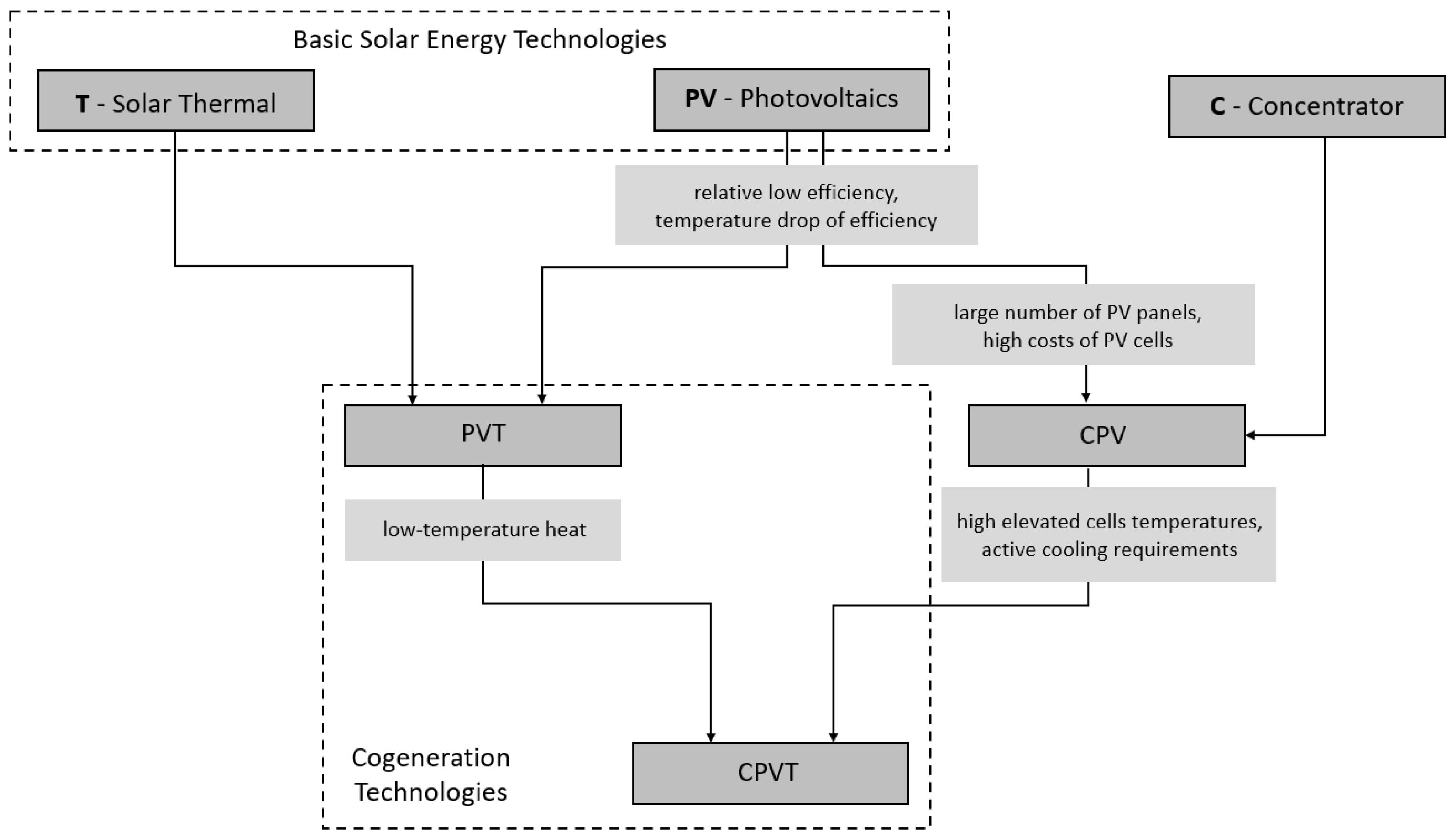
Figure 1. Evolution of basic solar energy technologies in CPVT system.
Energies 15 06123 g001
Figure 2. Energy flow in pre- and post-illumination cooling techniques.
Energies 15 06123 g002
Figure 3. The impact of high solar energy density and active cooling of PV cells on the performance of the CPVT system.
Energies 15 06123 g003
Figure 4. Applications of heat extracted from CPVT system depending on its temperature.
Energies 15 06123 g004
Figure 5. The cross-sectional view of typical rectangular-duct heat receiver.
Energies 15 06123 g005
Figure 6. The cross-sectional view of typical circular-duct heat receiver.
Energies 15 06123 g006
Figure 7. The cross-sectional view of the heat receiver tested in [83]. Dimensions in (mm). Reprinted with permission from Ref. [83]. 2019, Elsevier.
Energies 15 06123 g007
Figure 8. The cross-sectional view of the CPVT system tested in [84]. Reprinted with permission from Ref. [84]. 2011, Elsevier.
Energies 15 06123 g008
Figure 9. The cross-sectional view of CPVT system tested in [90].
Energies 15 06123 g009
Figure 10. The cross-sectional view of CHAPS receiver tested in [92]. Reprinted with permission from Ref. [92]. 2005, Elsevier.
Energies 15 06123 g010
Figure 11. Isometric view of heat receiver tested in [94]. Reprinted with permission from Ref. [94]. 2015, Elsevier.
Energies 15 06123 g011
Figure 12. The cross-sectional view of typical triangular-duct heat receiver.
Energies 15 06123 g012
Figure 13. The cross-sectional view of CPVT system tested in [95]. Reprinted with permission from Ref. [95]. 2017, Elsevier.
Energies 15 06123 g013
Figure 14. The cross-sectional view of heat receiver tested in [98].
Energies 15 06123 g014
Figure 15. The cross-sectional view of heat receiver tested in [42]. Reprinted with permission from Ref. [42]. 2018, Elsevier.
Energies 15 06123 g015
Figure 16. The cross-sectional view of typical heat receiver with internal channels.
Energies 15 06123 g016
Figure 17. The cross-sectional view of heat receiver tested in [99]. Reprinted with permission from Ref. [99]. 2019, Elsevier.
Energies 15 06123 g017
Figure 18. The cross-sectional view of the CPVT system and heat receiver tested in [101].
Energies 15 06123 g018
Figure 19. Schematics of the receiver of the CPVT-TE [15]. Reprinted with permission from Ref. [15]. 2020, Elsevier.
Energies 15 06123 g019
Figure 20. The cross-sectional view of a heat receiver with serpentine ducts—with direct and indirect connection between PV cells and cooling ducts.
Energies 15 06123 g020
Figure 21. Model of designed receiver [104]. Reprinted with permission from Ref. [104]. 2015, Elsevier.
Energies 15 06123 g021
Figure 22. Schematic view of a heat recovery coil circuit with marked PV cells [108].
Energies 15 06123 g022
Figure 23. Riser tubes in the squired-shaped receiver [109]. Reprinted with permission from Ref. [109]. 2022, Elsevier.
Energies 15 06123 g023
Figure 24. The cross-sectional view of a heat receiver with flow between two flat plates.
Energies 15 06123 g024
Figure 25. Model of designed hybrid receiver tube [111]. Reprinted with permission from Ref. [111]. 2020, Elsevier.
Energies 15 06123 g025
Figure 26. Two-dimensional sketch of the de-coupled PV/T system concept [112]. Reprinted with permission from Ref. [112]. 2015, Elsevier.
Energies 15 06123 g026
Figure 27. The cross-sectional view of a heat receiver with single-layer of microchannels.
Energies 15 06123 g027
Figure 28. A detailed schematic diagram of the microchannel heat receiver design showing two important variables in the configuration of heat sink: fin thickness (D) and fin height (H) [125]. Other symbols: W—spacing between fins, B—base thickness. Reprinted with permission from Ref. [125]. 2017, Elsevier.
Energies 15 06123 g028
Figure 29. Designs of microchannel heat receivers tested in [28]. Left: constant width of channels, right: stepwise-varying width. The direction of flow is marked with blue arrow. Reprinted with permission from Ref. [28]. 2017, Elsevier.
Energies 15 06123 g029
Figure 30. Hybrid cooling device (dimensions in mm) [67]. Reprinted with permission from Ref. [67]. 2014, Elsevier.
Energies 15 06123 g030
Figure 31. The cross-sectional view of a heat receiver with double-layer of microchannels.
Energies 15 06123 g031
Figure 32. Schematic of a CPV receiver attached to a heat sink [134]. Reprinted with permission from Ref. [134]. 2020, Elsevier.
Energies 15 06123 g032
Figure 33. Cross-section through smooth microchannel (SMC), offset ribs microchannel (OMC), and aligned ribs Microchannel (AMC) [137]. Reprinted with permission from Ref. [137]. 2018, Elsevier.
Energies 15 06123 g033
Figure 34. The studied flow fields/channel configurations for heat sinks [139]. Reprinted with permission from Ref. [139]. 2011, Elsevier.
Energies 15 06123 g034
Figure 35. Schematic diagram of the multi-layer manifold microchannel testing unit [140]. Reprinted with permission from Ref. [140]. 2015, Elsevier.
Energies 15 06123 g035
Figure 36. Pie chart showing the share of (a) HTF and (b) receiver material among papers regarding heat extraction devices with macroscale channels.
Energies 15 06123 g036
Figure 37. Pie chart showing the share of (a) HTF and (b) receiver material among papers regarding heat extraction devices with microscale channels.
Energies 15 06123 g037
Figure 38. Pie chart showing the share of individual geometry designs regarding heat extraction devices with (a) macroscale channels and (b) microscale channels.
Energies 15 06123 g038
Table 1. Advantages and disadvantages of CPVT systems.
AdvantagesDisadvantages
High thermal efficiencyNon-homogenous irradiance distribution
Medium- and high-temperature thermal outputSignificant optical losses
High electrical efficiency *Usage of only direct irradiation
Low elevated temperature of PV cellsPossibility of PV cells overheating/damage
Reduced area of PV cellsHigh complexity of the system
Lower investment costs in PV cells *Requirement for active cooling
Wide range of applicationsParasitic load connected with active cooling
Ease of integration with other devicesLimited maximum temperature of HTF
Cogeneration, trigeneration or polygeneration unit
* In the case of multi-junction solar cells.
Table 2. CPVT classification based on concentration ratio. Prepared on the basis of [4,32].
ConcentrationLowMediumHighUltra-High
CR [sun]<1010–100100–2000>2000
ConcentratorCompound Parabolic
V-trough
Linear Fresnel Reflector
Parabolic Trough
Linear Fresnel Lens
Parabolic dish
Central Receiver System
Fresnel Lens
Non-imaging dish concentrator
Parabolic dish+ Compound Parabolic
Central Receiver System+ Compound Parabolic
Fresnel Lens+ Compound Parabolic
Non-imaging dish concentrator+ Compound Parabolic
Irradiation utilizationDirect/Partially diffusiveDirectDirectDirect
Cooling requirementPassivePassive/ActivePassive/ActiveActive
TrackingNo/MaybeYesYesYes
Table 3. Advantages and disadvantages of liquid coolants used in CPVT systems. Prepared on the basis of [3,22].
Heat Transfer FluidAdvantagesDisadvantages
waterHigh heat capacity and thermal conductivity
Widely available and inexpensive
Environmentally friendly
Upper temperature limit 100 °C
Lower temperature limit 4 °C
Causes corrosion in hydraulic system Threat of Legionnaires disease
nanofluidsEnhanced thermal conductivity
Higher thermal efficiency than water
Bad performance in turbulent flows
Higher pressure drop than for water
Causes corrosion
Higher costs
diathermic oilHigh working temperatures (>100 °C)
Enhanced thermal efficiency
Significant thermal inertia
Reduced thermal conductivity
Higher pressure drop than for water
Not safe for environment
Table 4. Summary of discussed heat receivers with macro-scale channels.
Ref.ReceiverHeat Transfer FluidConcentratorPVEfficiency, %StudiesHighlights
DescriptionMaterialTypeCRElectricalThermalTotal
[8]Rectangular channel between two flat plates-1–10% Al2O3 nanoparticles
99–90% water
Parabolic dish88.3multi-crystalline silicon--45Numerical Nanofluids allow to control the temperature in a CPV receiver
[110]water--20–45Experimental, Numerical Cooling system enhances the electricalpower 2.5 times compared to a non-
concentrated PV. Inlet should be located in the upper part of receiver, outlet counter side.
[9]pipes placed under the plate, insulated at the bottom-glycol-waterFresnel lens/Parabolic dish 600–900triple-junction2067-NumericalThe outlet fluid temperature is 90C and allows one to use an AHP with
CPVT system
[10]rectangular tube, insulated at the sides and bottomaluminumWaterLinear Fresnel lenses80triple-junction34.75--NumericalSystem produced 5.1 MWh of thermal energy and 14.2 MWh of electricity
[15]parallel circular channels arrangedat equal spacing throughout the heat exchanger with common inlet andoutlet ports. TEGs between receiver and PV cells. aluminumwaterParabolic trough-monocrystalline silicon6.7647.35-Experimental, NumericalTEGs
improve the electrical efficiency by 7.46%
[21]triangular geometry receiveraluminumwaterParabolic trough14.8Back-contact monocrystalline silicon8.037.7-NumericalUpgrade of CT to CPVT required the change in receiver duct shape from circular to triangular
[42]triangular prism-shaped duct with PV panels on two sides and five cooling tubes beneath each panel, insulation on the third wallcopper70% wt. glycol 30% wt. waterlinear
Fresnel
15monocrystalline silicon12.858.071.8numericalDesigned system is able to provide heat and cool for residential building. Electrical energy has to be provided from the grid.
[75]insulated cooling plate-waterparabolic dish400triple-junction20>60>80Numerical
[76]rectangular channel from bent steel sheet under the PV cellssteelwaterV-trough-polycrystalline152035Experimental, TheoreticalDesign needs improvement in heat transfer and insulation to reduce thermal losses.
[77]Rectangular pipe-waterparabolic trough14.5Crystalline silicon10.216-experimental, numericalFurther work should be focused on geometry optimization
[78]thin-walled rectangular channel insulated at the sides and bottomaluminumwaterCompound parabolic 4Polycrystalline silicon--71Experimental, numericalElimination of multiple reflections enhances the CPVT performance
[99]rectangular channelaluminumwatercompound parabolic4Polycrystalline silicon1355-experimental, numericalThe steady-state model cannot predict the thermal performance in cases of rapid changes of solar radiation
[79]rectangular tube-WaterLinear Fresnel lenses25monocrystalline silicon1156-ExperimentalAR coatings and lamination of Fresnel lenses could improve the optical efficiency of the system.
[80]square pipe, insulated at the sides and bottomcopperwaterMiniature compound parabolic-Silicon9.5–10.631.2–37.2-Experimental, numericalminiature CPVT system has low heat losses so it could produce medium-temperature heat
[81]rectangular channel, with three wall insulationcopper0.2% Cu nanoparticles99.8% waterParabolic trough5–30Triple-junction---numericalNanofluid improves the thermal efficiency about 15% and electrical efficiency about 0.2%. Presence of insulation increases the thermal efficiency about 2%.
[82]water20---numericalTemperature gradient and hot spots lead to an average drop in thermal efficiency about 6%.
[83]insulated flat receiver with circular pipe-5% nanoparticles CuO
95% thermal oil (Syltherm 800)
Parabolic trough10Monocrystalline silicon6.646.84-numericalnanofluid leads to enhancement in thermal and electrical performance
[84]Insulated tubular ductAluminum alloywaterParabolic trough20silicon,
Supercell, GaAs cell
GaAs
9.88
Silicon 7.51
GaAs 49.84Silicon 42.4-experimentalThe electrical efficiency is the best for GaAs cell. CPVT system with silicon cells is economically viable.
[85]30.8Supercell 3.63%, GaAs 8.94%,
silicon 3.67%
Supercell 45.17%, GaAs 41.69%, silicon 34.53%-experimentalThe width of the solar cells should be adjusted to the width of focal spot to fully utilize concentrating irradiance.
[86]circular pipecopperwaterThree variants: hyperbolic trumpet,
V-trough, compound parabolic
1.94silicon18.44–18.59--numericalAll concentrators can generate almost the same electrical
power.
[87]tubecopperwaterparabolic trough90triple-junction---Experimental, numericalThe outlet fluid temperature above 80 °C allows integration of the sorption chiller.
[90]--water---6.1%69.6%-NumericalWithout the glass cover, the optical losses are reduced but the thermal losses increase.
[91]wedge receiver with angle of 20° between the two receiver copper plates.copper20% ethylene glycol
80% water
Parabolic trough2monocrystalline silicon8%59%-Experimentaldesign concept reduced the thermal stress and high radiation intensity over PV cells
[92]Circular tube with internal fins mounted under the flat plate absorber. Back and sides insulated and encased. aluminumWater
Anti-freeze additions
Parabolic trough37monocrystalline silicon115869ExperimentalInternal fins enhance the heat transfer rate. Illumination non-uniformities over the receiver surface have a significant effect on the overall electrical performance.
[93]Flat plate with circular, grooved tube on the rear sidealuminumwaterpoint-focus Fresnel lens1090triple-junction3030>60Experimental
[94]2854>80Experimental, numericalMainly the direct irradiance determines the
electrical and thermal performance of the system.
[95]equilateral triangle duct with TEG modules and PV cells on two sides and thermal insulation on the backsideironwater parabolic trough8.34monocrystalline siliconWith glass coverexperimentalPresence of glass cover increases the thermal efficiency and decreases the electrical efficiency. Non-uniform irradiation distribution through receiver decreases the electrical efficiency of PV cells.
4.8346.1650.99
Without glass cover
4.9442.3647.30
[96]---numericalOptimum reflector aperture width 1.6–2.2 m and optimum apex angle 80°–120°.
[97]Triangular duct with PV cells on two sidesaluminumwaterParabolic trough7.8Monocrystalline silicon6.4--experimentalIrradiation intensity is an essential factor determining the amount of generated energy
[98]linear triangular receiver with circular fluid channel inside-waterparabolic trough110triple-junction 20–2560–65-NumericalInsulating the top surface is recommended to increase the electrical efficiency
[100]Flat plate with eight channels with different cross-sections: ellipse, rectangle, circle, squarealuminumwatera combination of involute, circular and parabola shape-Monocrystalline silicon17.8–19.0--numericalelliptical channels
ensure the most uniform distribution of
the temperature
[102]Flat plate with parallel elliptic channels, insulated. TEGs between receiver and PV cells.-0.5% graphene
99.5% water
--silicon cell---NumericalTEGs
improve the electrical efficiency by 5–10%
[103]Rectangular tube with circular inner channel, bend in U shape to provide counter-flowaluminumwaterlow profile linearparabolic20monocrystalline silicon-64-experimental, numerical The maximal outlet temperature is limited by the U-shaped geometry of the water channel. Two separate channels may provide higher outlet temperature.
[104]U-shaped, two parallel copper tubes which are connected together with rubber tube, insulatedcopperwaterFresnel lenses-triple-junction --76experimental, numericalFlow rate allows to control thermal and electrical power. Optimum value was found to be 0.033 kg/s
[105]double tubular pipealuminumwaterParabolic trough8.5Monocrystalline silicon8.345-experimentalOperating temperature of PV cell is reduced under 60 °C. Electricity production in CPVT system is 4.7–5.2 times higher than for PV
[106]Rectangular receiver with 2, 3, 4 or 6 internal channelsaluminumwaterparabolic trough-Monocrystalline silicon8.45–9.3059.8–74.2-NumericalThe higher number of pipes, the higher total performance. Rectangular pipes reduce cell temperature by 17 °C
[107]Circular pipe in meander configurationcopperglycol-waterFresnel lens + kaleidoscope208.6triple-junction23–29--Numericalkaleidoscope allows to uniform the solar irradiance on the surface of the cell
[109]squired-shaped riser tubes surrounded by the metallic substrate and insulated upper wall-six engine oil-based nanofluidsParabolic dish-triple-junction---numericalNanofluids enhance the total efficiency and increase the pressure drop
[114]Header-riser structurecopperwaterConcentrated dish600–800triple-junction483885numericalActive cooling enhances electrical efficiency of the system and increases the total efficiency up to 85%
[111]D-shaped receiver (semi- cylindrical tube)copperwaterparabolic trough6monocrystalline silicon12.3949.48-analytical,
experimental
Cooling efficiency strongly depends on the mass flow rate of the HTF.
[112]C-shaped, HTF flows above and below the PV cell. Vacuum between PV cell and upper layer of coolantglass2% SiO2 nanoparticles98% water -40, 100, 150Monocrystalline silicon--25.5 (CR = 40), 16.7 (CR = 100) 16.2 (CR = 150)numericalNanofluids significantly enhance the heat transfer
[113]Tube bent into spiral shape. Inlet close to the edge, outlet in the middle. copperwaterFresnel lens -semi-transparent CdTe2.6–3.455–65 ExperimentalUsage of red filter above PV cell allows to increase thermal and electrical efficiencies
[115]Commercial thermal collector-waterV-trough2Monocrystalline silicon---Experimental, numerical31.5% increase in electric power due to the active cooling of PV cells in CPVT system
[116]Cylindrical receiver with M-shaped internal channelaluminumthermal oilDouble parabolic dish105----NumericalThe reduction of absorber temperature is required
[117]Roll bond plate with ductaluminumwaterparabolic trough130triple-junction10–2040–6070Experimental, numericalIt is possible to increase the operating temperature of PV cell to produce heat at medium temperature (80–90 °C)
[118]rectangular channel, insulation on the back and side wallsaluminumwaterFresnel lens and flat mirrors5Monocrystal-line silicon1056-experimental, numericalDouble optics makes the irradiation distribution over PV cells surface more uniform
[119]rectangular duct with insulation on three sidesaluminumwaterParabolic trough53-22.261.683.8Numerical Payback time is only 5.6 years
[120]Flat plat absorber with circular tubecopper4–20% TiO2
96–80% water
parabolic trough15Supercell,
GaAs
Supercell 11.67
15.55
Supercell 68.5
5.93
Supercell 79.12
6.97
Elongation of receiver tube reduces the total efficiency. Nanofluids are more effective for laminar flow.
Table 5. Summary of discussed heat receivers with micro-scale channels.
Ref.ReceiverHeat Transfer FluidConcentratorPVEfficiency, %StudiesHighlights
DescriptionMaterialTypeCRElectricalThermalTotal
[28]elongated plate-fin heat sink with microchannels of constant or stepwise-varying width configurationaluminumwaterparabolic trough14.3monocrystalline silicon64450experimentalFins with varying width significantly reduce pumping power
[30]Heat sink with pin fins: in-line cylindrical, staggered cylindrical, in-line conical, and staggered conicalAluminum/copperwaterFresnel lens500–2500Multi-junction--80numericalcylindrical-shaped pin fins are suitable for CR < 2500, whereas conical-shaped only for CR < 2000. Staggered configuration reduces pressure drop.
[67]jet impingement microchannel with varying width of channels-waterParabolic (primary optics),
Kaleidoscope (secondary optics)
537dummy---experimentalstep varying width of the microchannel
sections reduce the pressure drop and thermal resistance along the flow, resulting in a uniform
temperature distribution.
[123]Rectangular with insulated enclosurealuminumWater;
Al2O3
Water/oil
--Multi-junction---numericalThe thinner fins, the better thermal and hydraulic performance
[104]Eight designs of channel configurations: serpentine, parallel, parallel with manifolds, distributor (each type with and without transverse slots)aluminumdeionized water-40/50----numericalDistributors provide uniform flow uniformity, surface temperature distribution and low-pressure loss.
[124]Heat sink with parallel microchannels immersed in flowing water-waterFresnel Lens70, 100, 130Multi-junction/Laser Grooved Buried Contact silicon ---ExperimentalTEGs enhance the overall output power, but PV performs better when connected directly to the heat sink
[125]multiple-channel heat sink with parallel long plate fins-waterPrimary: dish concentrator, secondary: array of compound parabolic lenses1800Triple-junction31.8--numericalHigher number of fins contribute to larger heat transfer area.
It is possible to maintain cell temperature below 100°
[126]elongated plate heat sink with channels of stepwise decreasing hydraulic diameteraluminumwaterlinear-----numericalThe buoyancy in the first heat sink section has a beneficial impact on thermal performance. Enhanced eat transfer due to contraction-induced vortices.
[128]stepwise varying width microchannel with fins of different lengthAluminumwaterFresnel lens1000Multi-junction38–40--numericalHhigher flow rates and increase in number and length of fins lead to lower thermal resistance and higher pressure drop
[129]jet impingement microchannel with varying width of channels. Inlet located under the central part of the receiver.AluminumwaterFresnel lenses1000Multi-junction39.760.4-numericalLocation of inlet under the central part of the receiver provides a higher reduction in the maximum temperature
[130]tree-shaped channel -water-50Silicon---numericalTree shaped channel provides 10 °C lower temperature of PV cell than straight channel
[134]Multi-layered heat sink with parallel flowaluminumwaterprimary and secondary reflector529triple-junction9.8--experimentalHeat sink with 3-layers provided an increase in electrical power of 9.4% compared to the 1-layer
[135]Five configurations of microchannel: wide rectangular, single-layer parallel-flow, single-layer counter-flow, double-layer parallel-flow, double-layer counter-flowaluminumwaterlinear Fresnel lens20polycrystalline silicon---numericalThe best design for PV cooling: single-layer heat sink with parallel-flow.
The worst design: single-layer heat sink with counter-flow
[137]Microchannels with forward triangular ribs on sidewalls in aligned and offset distribution siliconwaterFresnel lens1000Multi-junction40--numericalForward triangular ribs installed on the sidewalls enhance the heat transfer capability
[138]Heat sink with Round Pins and Straight Finsaluminumwater-500triple-junction39.5--Experimental, nu-mericalThe heat sink with straight fins keeps the PV surface temperature lower than that of a sink with round pins
[140]Three layers: the microchannels, the manifolds, and the plenum chamber with ductscopper, steelwater-≤98silicon---experimentalMulti-layer design maximizes the contact area between the microchannels and the cell surface. A short flow path reduces pressure drop.
[141]porous channel collector with rectangular cross-sectionAluminum foamAl2O3 nanoparticles
water
Parabolic trough-Monocrystal-line silicon18.8–19.7-62–73numerical
[142]Heat sink mounted on the circular pipecopperwaterFresnel Lens784Multi-junction36.549.568.7Experimental, numericalNumerical model gives higher efficiencies than experimental tests due to the heat losses associated to experiment.
[143]Rectangular duct with aspect ratio 8, 106 parallel microchannelsaluminumwater-20polycrystalline silicon17.570.8-numericalAspect ratio eight provides maximum heat transfer coefficient for the rectangular ducts.
For CR > 3.5 cooling system is recommended.
Table 6. Comparison of heat extraction devices with micro- and macro-scale channels.
Discussed AspectMacroscale ChannelsMicroscale Channels
ShapeStraight ducts with rectangular or triangular cross-section,
Metal blocks with internal channels,
Serpentine channels arrangement,
Flow between two flat plates
Single- or multi-layered
Microchannels, constant or varying spacing between fins and fin thickness,
Various shapes of pin-fins
Heat transfer fluidUsually: Water,
Nanofluids,
Water—glycol solutions,
Rare: Thermal Oils
Usually: Water,
Nanofluids,
Rare: Thermal oils
Concentration RatioUsually low and mediumUsually high and ultrahigh
Accompanying
concentrator
V-trough, compound parabolic, linear Fresnel lensesParabolic trough, parabolic dish, Fresnel lenses, presence of secondary optics such as a kaleidoscope
Accompanying PV cell Usually crystalline Silicon cells,
but also: thin-film cells,
multi-junction cells
Usually multi-junction cells,
but also: crystalline silicon cells,
thin-film cells,
Pressure dropStrongly depends on the shape and length of the channelsVery high
ManufacturingSimple constructions based on commercially-available componentsRequires specified machines and processes
Advantages
  • simple design
  • easy to manufacture
  • lightweight
  • capable of removing high amounts of heat from a very small area
Disadvantages
  • limited heat transfer efficiency
  • some designs may be hard to manufacture at reasonable costs
  • require precise solar tracking
Publisher’s Note: MDPI stays neutral with regard to jurisdictional claims in published maps and institutional affiliations.