
DC Soft Open Points for Resilient and Reconfigurable DC Distribution Networks


Abstract
:1. Introduction
1.1. Need for DC Network Reconfiguration
1.2. Reliability Assessment of Reconfigurable DC Microgrids
- Loss of load expectation (LOLE),
- Loss of load probability (LOLP),
- Expected energy not supplied (EENS),
- System average interruption frequency index (SAIFI),
- Customer average interruption frequency index (CAIFI),
- System average interruption duration index (SAIDI),
- Customer average interruption duration index (CAIDI).
1.3. Agent-Based Control of Reconfigurable DC Microgrids
1.4. Contributions to Knowledge
2. Materials and Methods
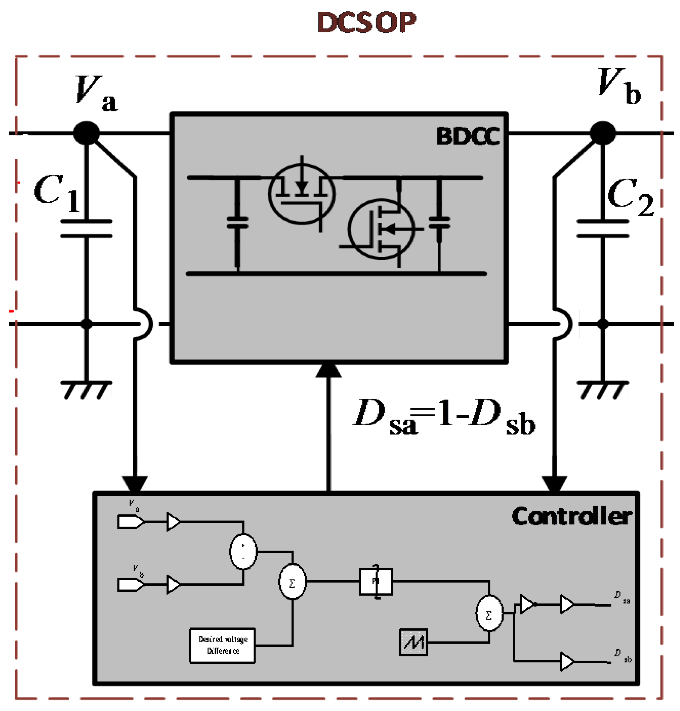
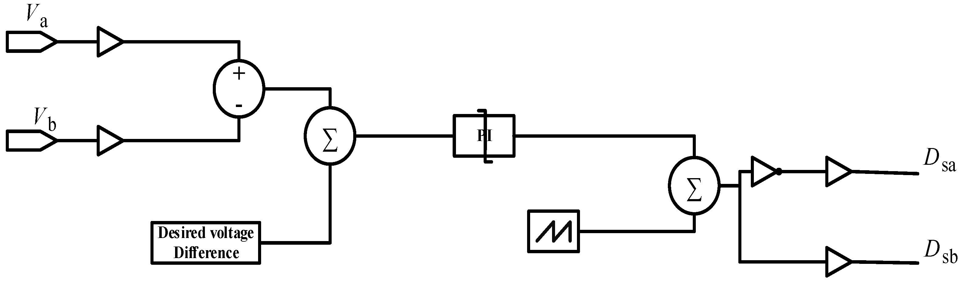
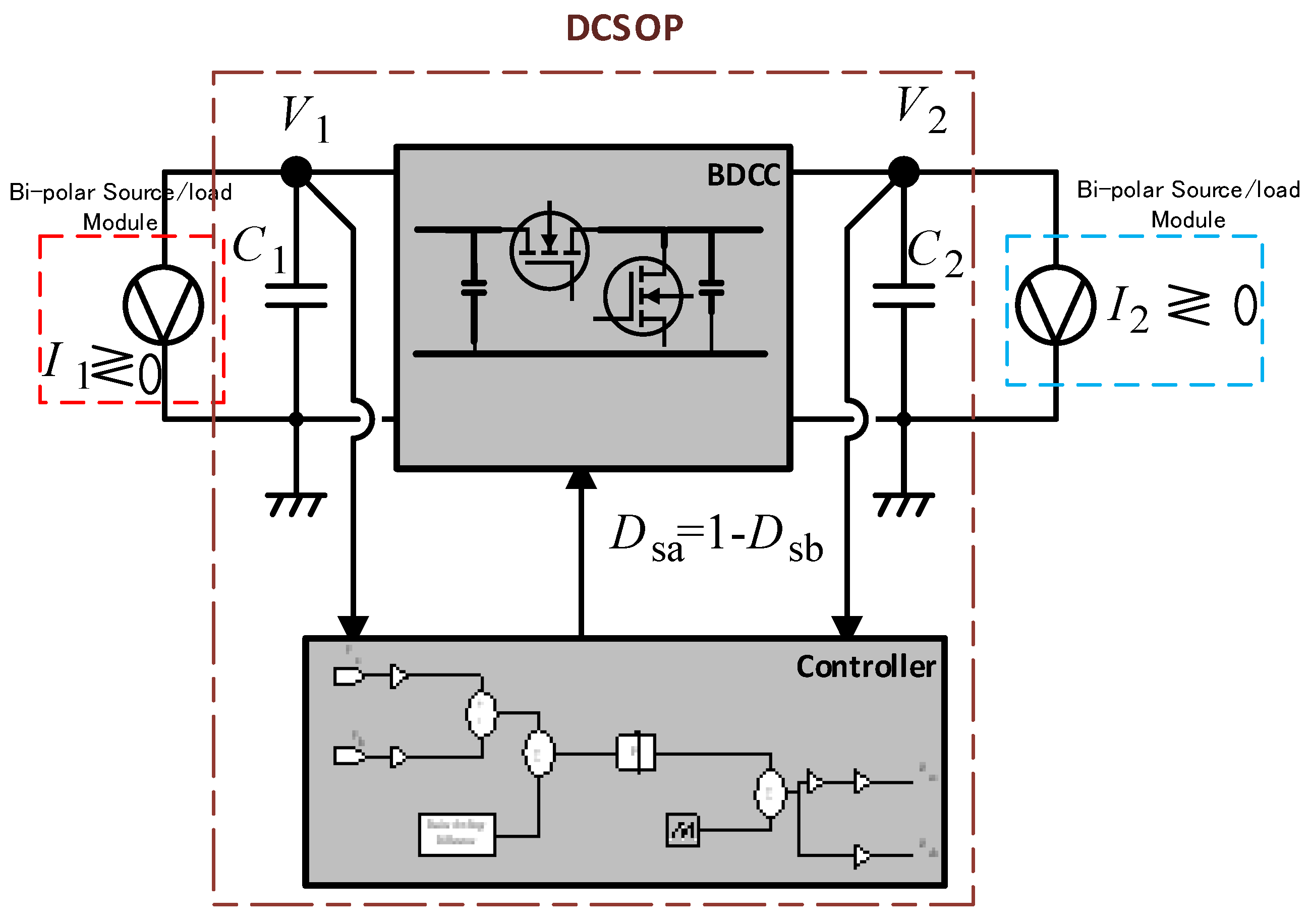
2.1. DC Soft Open Point (DCSOP)
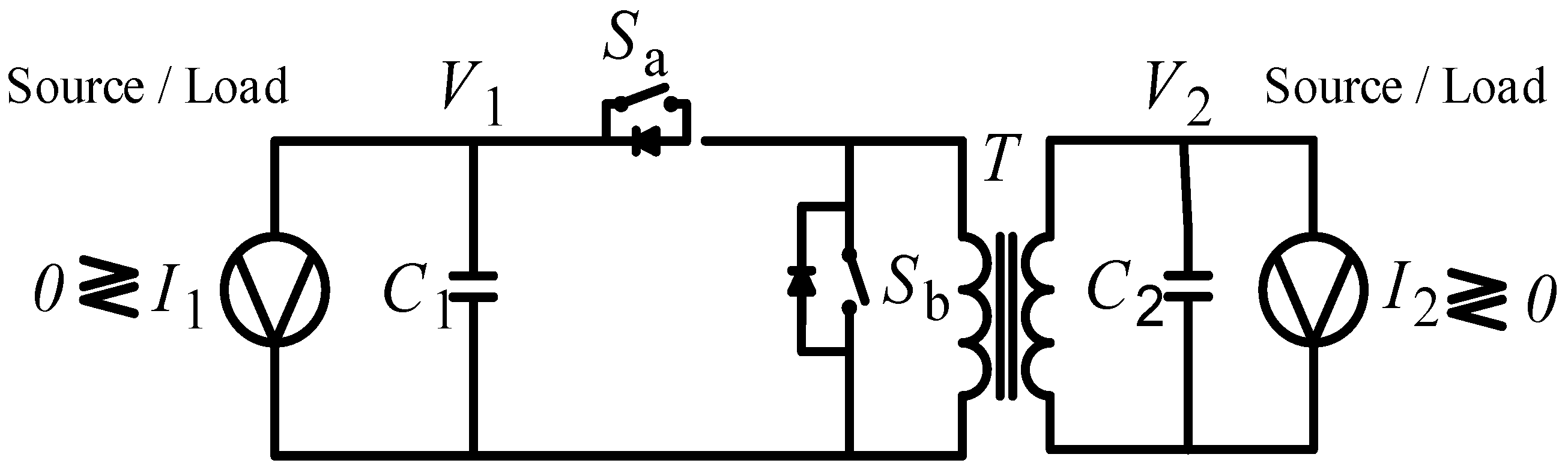
2.1.1. Implementation of the DCSOP Using a Bi-Directional DC–DC Converter
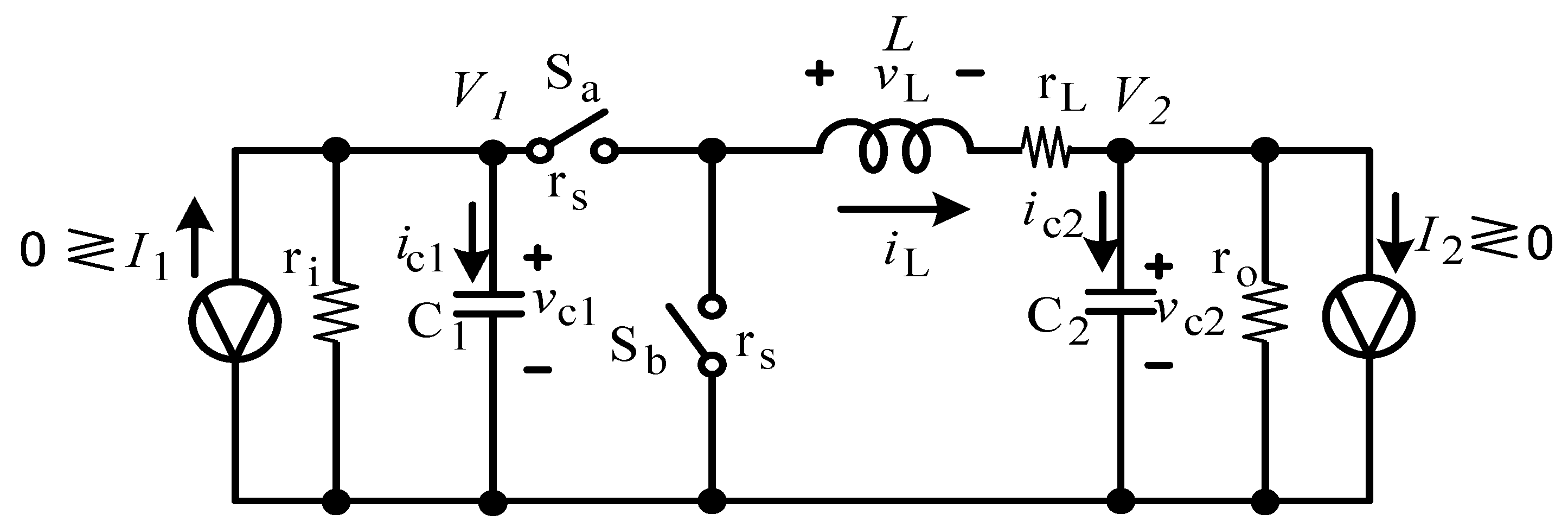
2.1.2. Seamless Averaged Model for the DCSOP
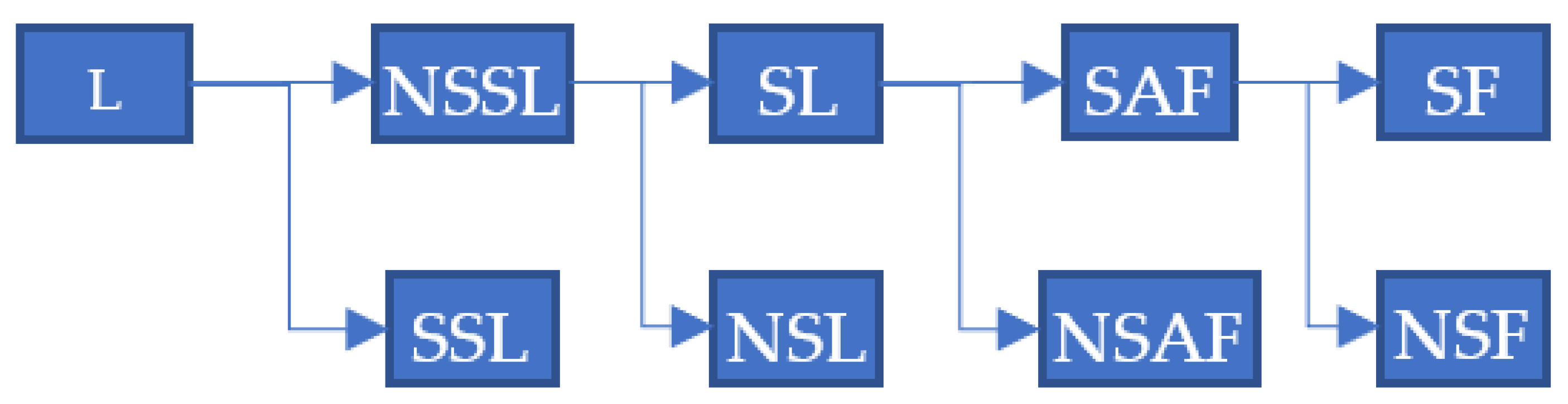
2.2. Reliability Assessment Method
2.2.1. Reliability Analysis Sets
2.2.2. Reliability Indices
- SAIDI (system average interruption period index) is the average interruption period per customer served.
- CAIDI (customer average interruption period index) is the average interruption period for those customers interrupted during a year.
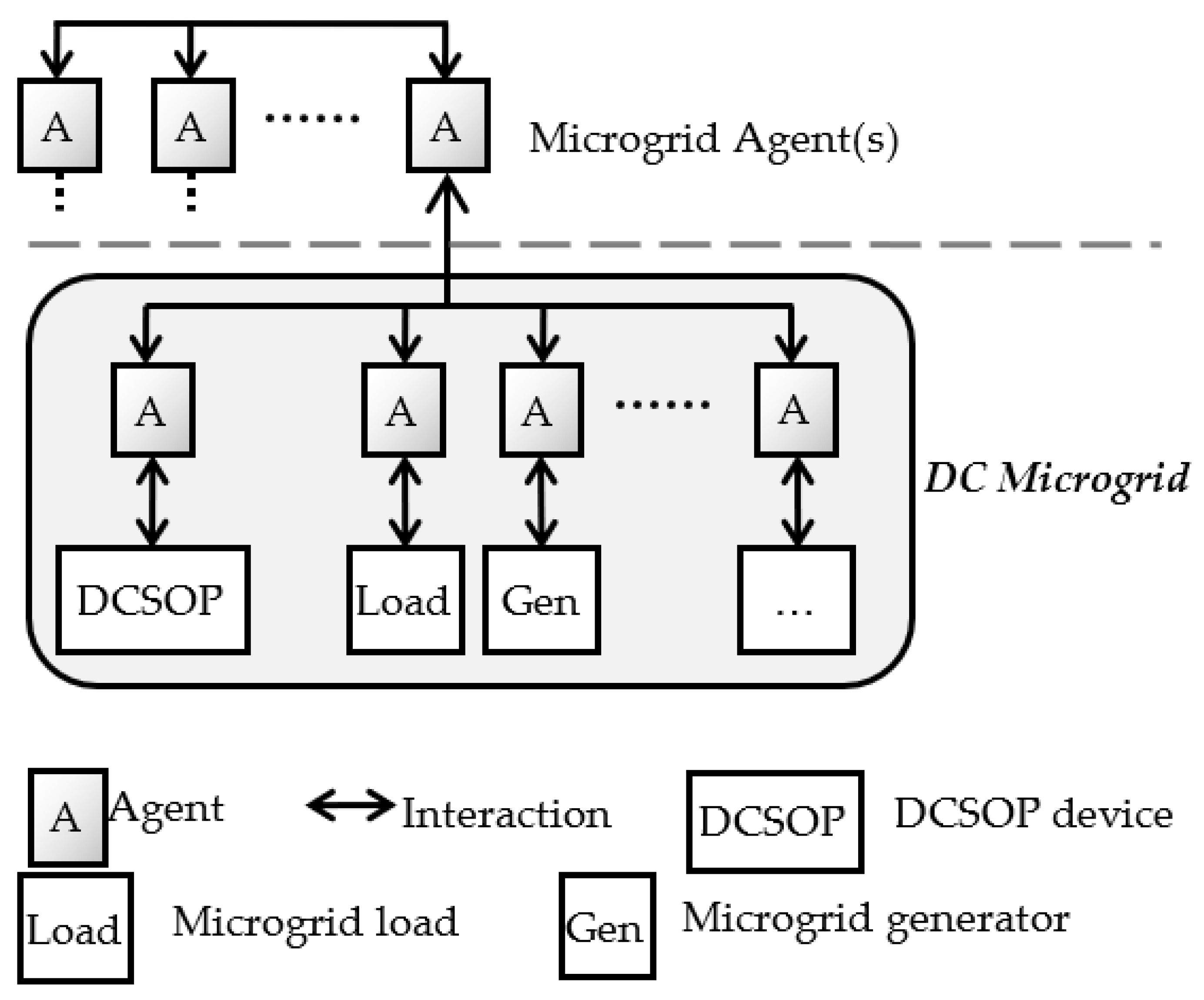
2.3. Agent-Based Model
2.3.1. Microgrid/Network Agent
- Calculate power flows and operational parameters based on the different measurement points in the microgrid/network.
- Communicate with DCSOP agents and other agents, and provide information and knowledge gained from overseeing the operation of the network.
- Send direct requests to particular equipment agents to act in specific ways.
- Communicate with other DCSOP, load, power flow or other network agents in order to establish joint decision making.
- Communicate with other, adjacent microgrid agents, in case there is any synergy that can be gained, such as load reduction to prevent load shedding.
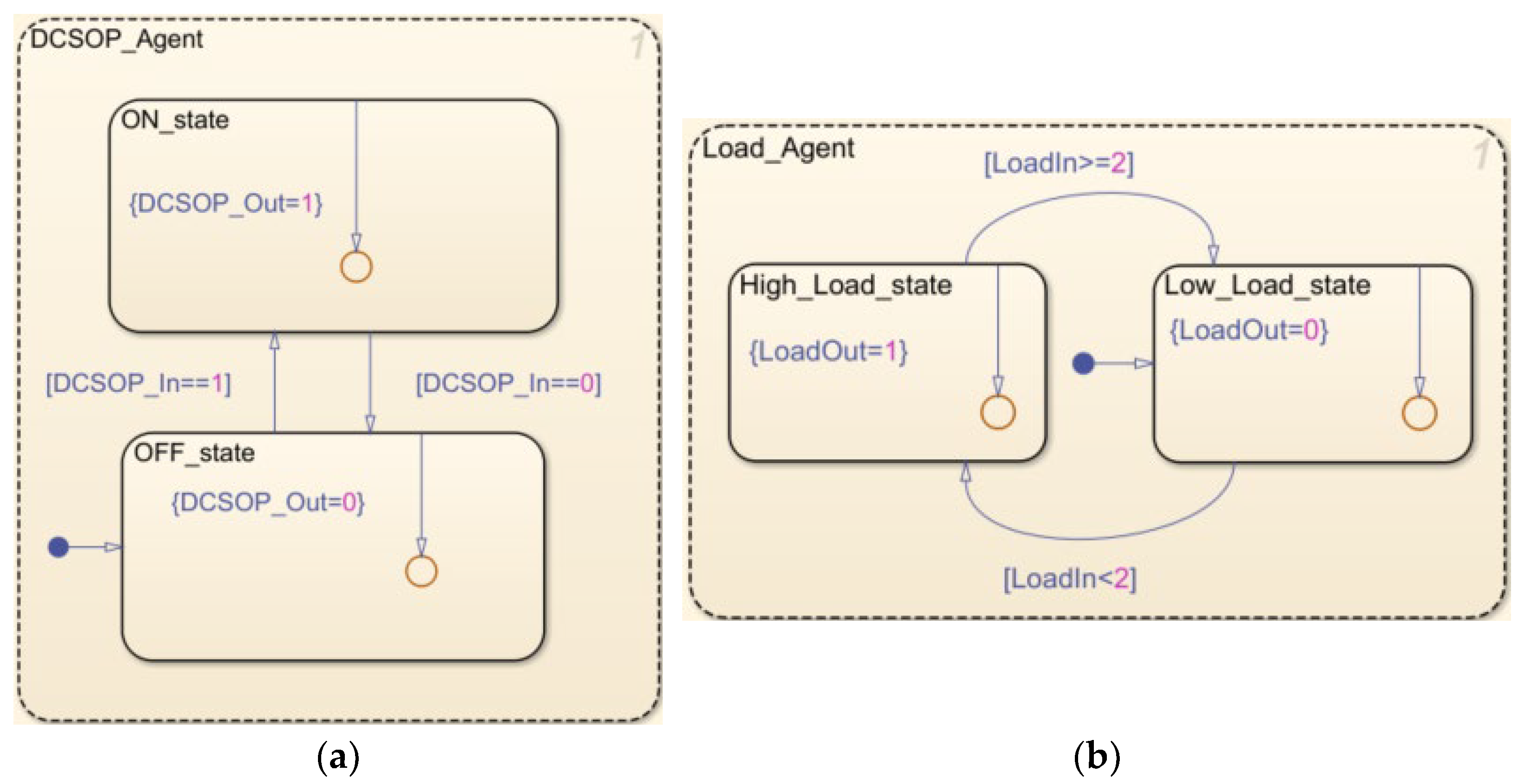
2.3.2. DCSOP Agent
- Communicates with other agents (e.g., load agents) and receives messages from them on various conditions in the network.
- Makes decisions regarding the state of the network and whether there is a need to act or not.
- Communicates with other DCSOP, load, power flow or other network agents in order to establish joint decision making.
- Sends commands to the DCSOP device, enabling it to transition from the ON to the OFF state, and vice versa.
- Receives measurements on different parameters from the DCSOP in order to check on the state of the device.
2.3.3. Generator/Load Agent
- Communicates with other agents (e.g., DCSOP or microgrid agents) and sends messages to them regarding various parameters associated with their generator or load.
- Makes decisions regarding the local state of the network and whether there is a need to act or not (e.g., generator disconnection, load shedding).
- Communicates with other DCSOP, load, power flow or other network agents in order to establish joint decision making.
2.3.4. Multi-Agent System Structure
2.3.5. Agent Implementation in MATLAB/Simulink Stateflow
3. Results and Discussion
3.1. DCSOP Characterisation Case Studies
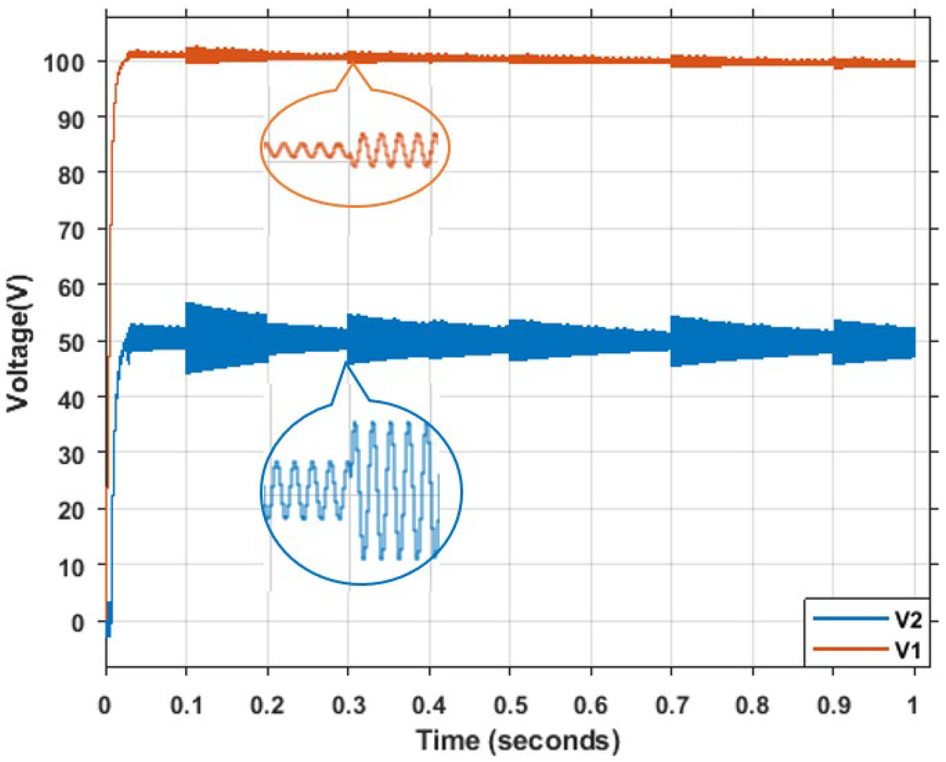
3.2. DCSOP Stress Test
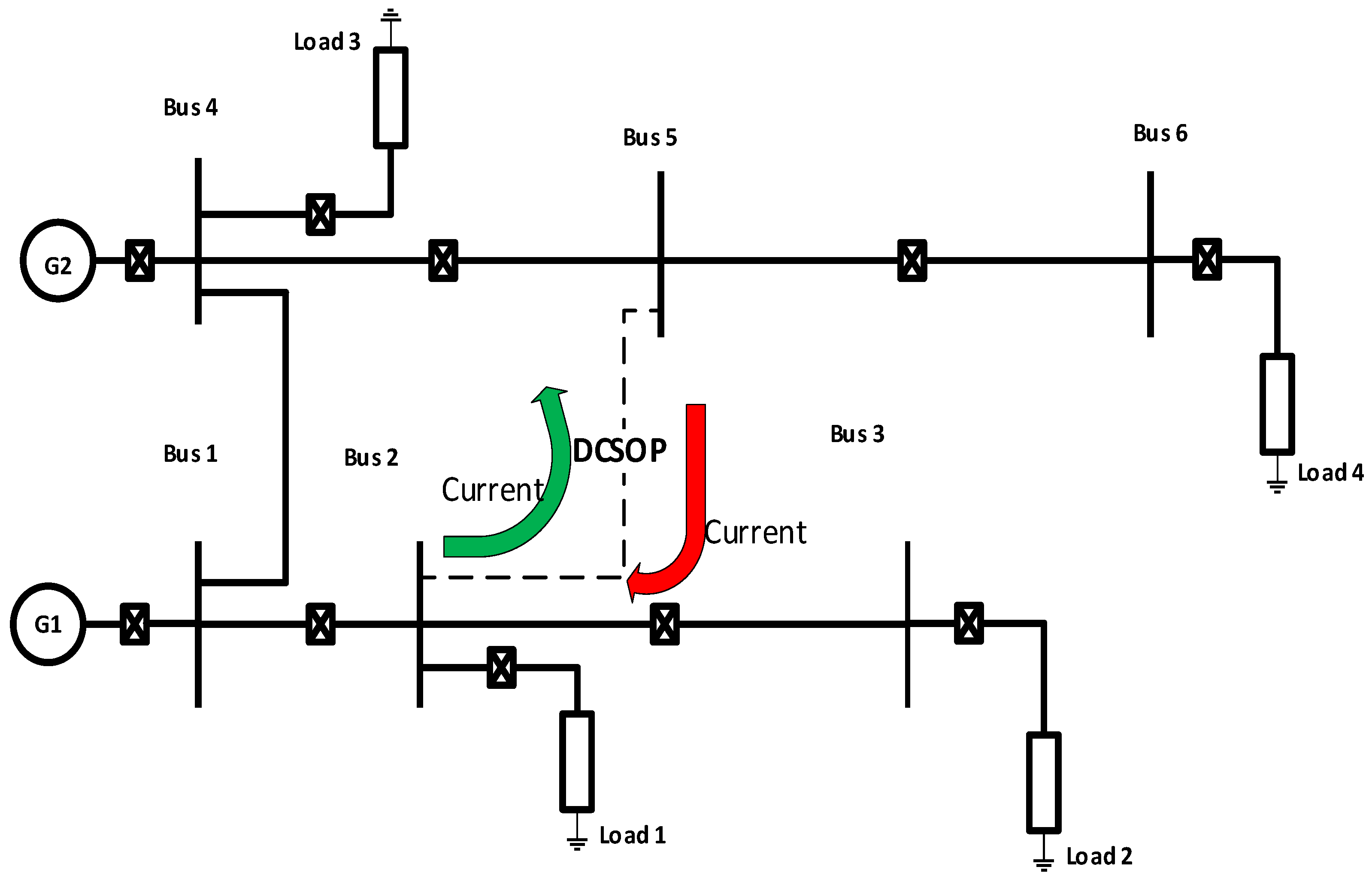
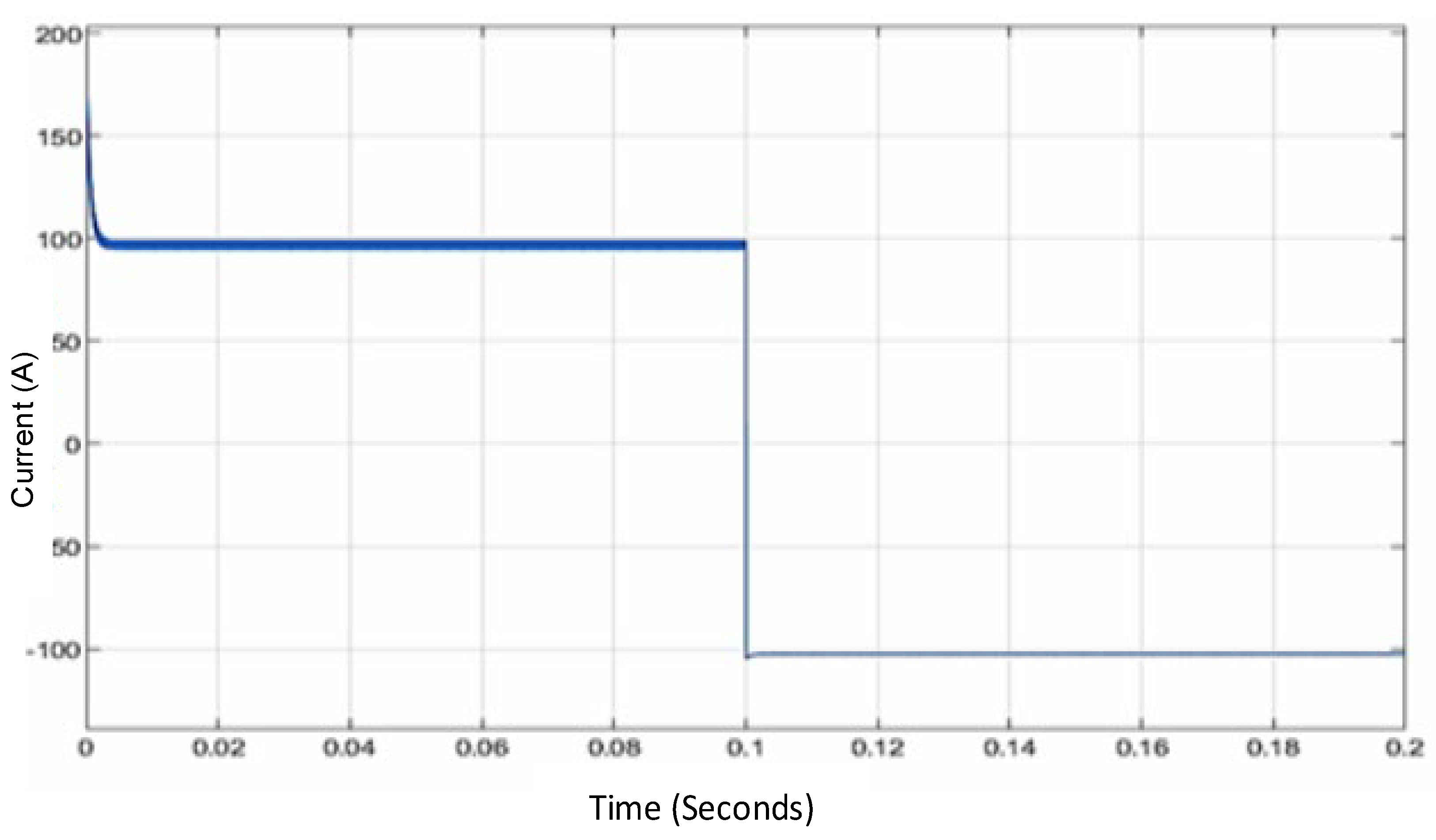
3.3. Control of Current Flow Direction
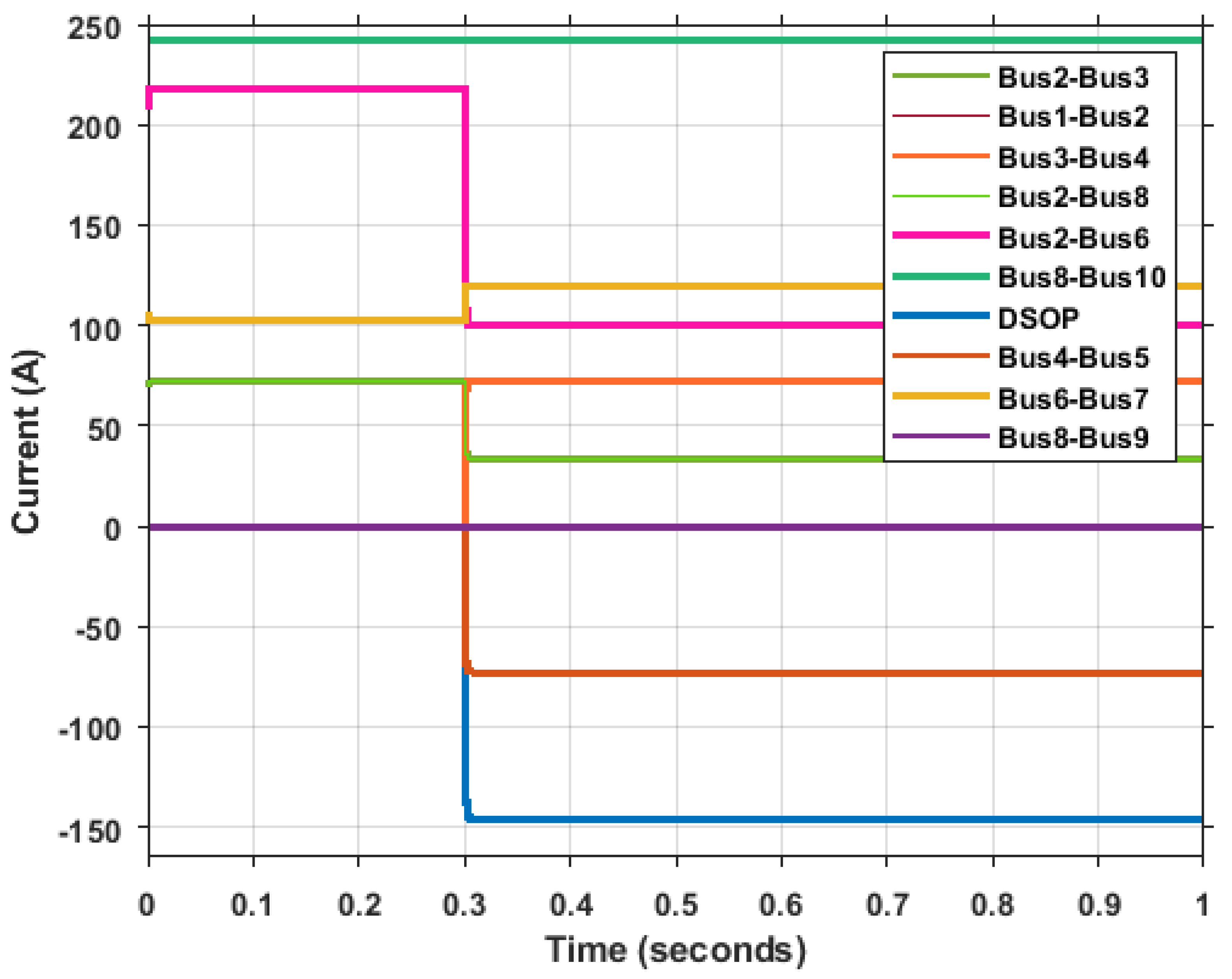
3.4. Replacing NOP with DCSOP in a DC Microgrid
3.5. Replacing NOP with a Normal Conductor in a DC Microgrid
3.6. Impact of DCSOP on Reliability of Reconfigurable DC Microgrids—Case Studies
3.6.1. Case R.1: Base Case, No DCSOP
- CAIDI: 1.269,
- SAIDI: 1.0497.
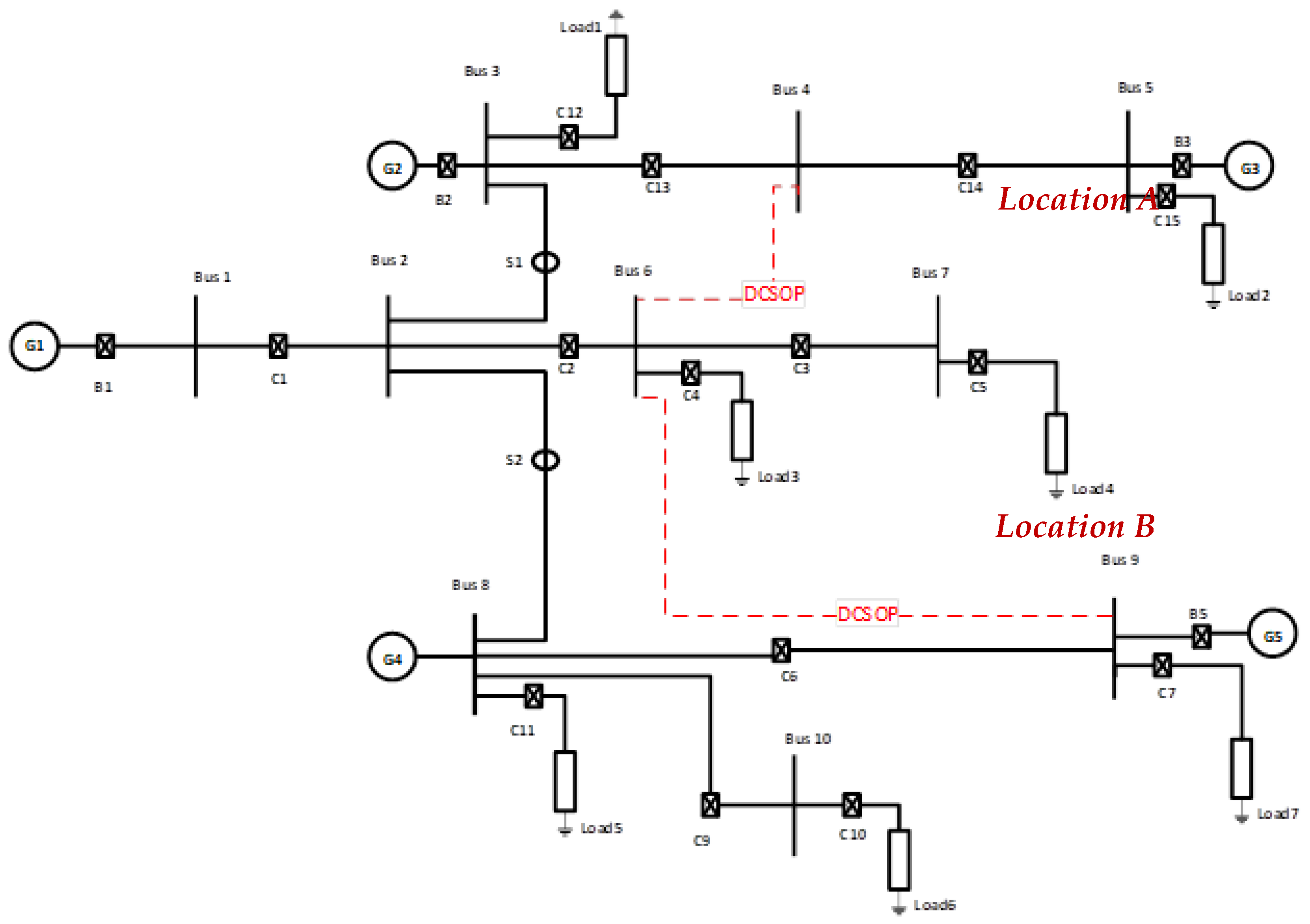
3.6.2. Case R.2: One DCSOP, Location A
- CAIDI: 0.961,
- SAIDI: 0.964.
3.6.3. Case R.3: One DCSOP, Location B
- CAIDI: 0.964,
- SAIDI: 0.7461.
3.6.4. Case R.4: Two DCSOPs, Locations A and B
- CAIDI: 0.658,
- SAIDI: 0.656.
3.6.5. Summary and Comparison of Reliability Cases
3.7. Testing of Agent-Based Control of DCSOP for DC Network Reconfiguration
4. Conclusions
- Being able to control the power flows, and
- Being able to connect two buses operating at different voltages.
Author Contributions
Funding
Institutional Review Board Statement
Informed Consent Statement
Conflicts of Interest
Appendix A

| Branches | R/Ω | Loads | Rating/KW | Generators | Rating/V |
|---|---|---|---|---|---|
| Bus 1–Bus 2 | 1.32 | Load 1 | 100 | G1 | 400 |
| Bus 2–Bus 3 | 1.32 | Load 2 | 60 | G2 | 400 |
| Bus 3–Bus 4 | 1.32 | Load 3 | 60 | G3 | 400 |
| Bus 4–Bus 5 | 1.32 | Load 4 | 60 | G4 | 400 |
| Bus 2–Bus 6 | 1.32 | Load 5 | 30 | G5 | 400 |
| Bus 6–Bus 7 | 1.32 | Load 6 | 30 | ||
| Bus 2–Bus 8 | 1.32 | Load 7 | 60 | ||
| Bus 8–Bus 9 | 1.32 | ||||
| Bus 8–Bus 10 | 1.32 |
References
- Fuad, K.S.; Hafezi, H.; Kauhaniemi, K.; Laaksonen, H. Soft Open Point in Distribution Networks. IEEE Access 2020, 8, 210550–210565. [Google Scholar] [CrossRef]
- Giannelos, S.; Konstantelos, I.; Strbac, G. Option value of Soft Open Points in distribution networks. In Proceedings of the 2015 IEEE Eindhoven PowerTech, Eindhoven, The Netherlands, 29 June–2 July 2015; 2015; pp. 1–6. [Google Scholar] [CrossRef]
- Bloemink, J.M.; Green, T.C. Increasing distributed generation penetration using soft normally-open points. In Proceedings of the IEEE PES General Meeting, Providence, RI, USA, 25–29 July 2010; pp. 1–8. [Google Scholar]
- Cao, W.; Wu, J.; Jenkins, N.; Wang, C.; Green, T. Benefits analysis of Soft Open Points for electrical distribution network operation. Appl. Energy 2016, 165, 36–47. [Google Scholar] [CrossRef]
- Li, P.; Ji, H.; Yu, H.; Zhao, J.; Wang, C.; Song, G.; Wu, J. Combined decentralized and local voltage control strategy of soft open points in active distribution networks. Appl. Energy 2019, 241, 613–624. [Google Scholar] [CrossRef]
- Ismail, M.; Hassane, E.; Hassan, E.M.; Tijani, L. Power losses minimization in distribution system using soft open point. In Proceedings of the 2020 1st International Conference on Innovative Research in Applied Science, Engineering and Technology (IRASET), Meknes, Morocco, 16–19 April 2020; pp. 1–5. [Google Scholar]
- Yang, Y.; Zhang, S.; Pei, W.; Sun, J.; Lu, Y. Network reconfiguration and operation optimisation of distribution system with flexible DC device. J. Eng. 2019, 2019, 2401–2404. [Google Scholar] [CrossRef]
- Aithal, A.; Long, C.; Cao, W.; Wu, J.; Ugalde-Loo, C.E. Impact of soft open point on feeder automation. In Proceedings of the 2016 IEEE International Energy Conference (Energycon), Leuven, Belgium, 4–8 April 2016; pp. 1–6. [Google Scholar]
- Aithal, A.; Li, G.; Wu, J.; Yu, J. Performance of an electrical distribution network with Soft Open Point during a grid side AC fault. Appl. Energy 2018, 227, 262–272. [Google Scholar] [CrossRef]
- Cao, W.; Wu, J.; Jenkins, N. Feeder load balancing in MV distribution networks using soft normally-open points. In Proceedings of the IEEE PES Innovative Smart Grid Technologies, Europe, Istanbul, Turkey, 12–15 October 2014; pp. 1–6. [Google Scholar]
- Olowookere, O.; Skarvelis-Kazakos, S.; Habtay, Y.; Woodhead, S. Fault ride through during loss of converter in a 4-VSC based HVDC transmission. In Proceedings of the IEEE PES Innovative Smart Grid Technologies Conference Europe, Istanbul, Turkey, 12–15 October 2014; pp. 1–6. [Google Scholar]
- Ji, H.; Wang, C.; Li, P.; Zhao, J.; Song, G.; Ding, F.; Wu, J. An enhanced SOCP-based method for feeder load balancing using the multi-terminal soft open point in active distribution networks. Appl. Energy 2017, 208, 986–995. [Google Scholar] [CrossRef]
- Bloemink, J. Distribution Level Power Electronics: Soft Open-Points (SOPs). Ph.D. Thesis, Imperial College, London, UK, 2013. [Google Scholar]
- Daniel, S.; Skarvelis-Kazakos, S.; Jain, P. Local smart DC networks and distributed storage for reducing and shifting peak load. In Proceedings of the 22nd International Conference on Electricity Distribution (CIRED), Stockholm, Sweden, 10–13 June 2013. [Google Scholar]
- Gopinathan, S.; Rao, V.S.; Kumaravel, S. Family of Non-Isolated Quadratic High Gain DC-DC Converters based on Extended Capacitor-Diode Network for Renewable Energy Source Integration. IEEE J. Emerg. Sel. Top. Power Electron. 2022. [Google Scholar] [CrossRef]
- Iovine, A.; Carrizosa, M.J.; De Santis, E.; Di Benedetto, M.D.; Pepe, P.; Sangiovanni-Vincentelli, A. Voltage Regulation and Current Sharing in DC Microgrids with Different Information Scenarios. IEEE Trans. Control Syst. Technol. 2021. [Google Scholar] [CrossRef]
- Heydari-doostabad, H.; O’Donnell, T. A Wide-Range High-Voltage-Gain Bidirectional DC–DC Converter for V2G and G2V Hybrid EV Charger. IEEE Trans. Ind. Electron. 2022, 69, 4718–4729. [Google Scholar] [CrossRef]
- He, P.; Khaligh, A. Comprehensive Analyses and Comparison of 1 kW Isolated DC–DC Converters for Bidirectional EV Charging Systems. IEEE Trans. Transp. Electrif. 2017, 3, 147–156. [Google Scholar] [CrossRef]
- Rahimi, R.; Habibi, S.; Ferdowsi, M.; Shamsi, P. Z-Source-Based High Step-Up DC-DC Converters for Photovoltaic Applications. IEEE J. Emerg. Sel. Top. Power Electron. 2021. [Google Scholar] [CrossRef]
- Kwasinski, A.; Onwuchekwa, C.N. Dynamic behavior and stabilization of DC microgrids with instantaneous constant-power loads. IEEE Trans. Power Electron. 2011, 26, 822–834. [Google Scholar] [CrossRef]
- Billinton, R.; Li, W. Reliability Assessment of Electric Power Systems Using Monte Carlo Methods; Plenum Press: New York, NY, USA, 1994. [Google Scholar]
- Billinton, R.; Jonnavithula, S. A test system for teaching overall power system reliability assessment. IEEE Trans. Power Syst. 1996, 11, 1670–1676. [Google Scholar] [CrossRef]
- Kjølle, G.; Jakobsen, S.H.; Baldursson, F.M.; Galant, S.; Haarla, L. State of the Art on Reliability Assessment in Power Systems Including Socio-Economic Impact. GARPUR Deliverable D1.1. 2014. Available online: https://www.sintef.no/globalassets/project/garpur/deliverables/garpur-d1.1-state-of-the-art-on-reliability-assessment-in-power-systems.pdf (accessed on 1 November 2021).
- Heylen, E.; Deconinck, G.; Hertem, D.V. Review and classification of reliability indicators for power systems with a high share of renewable energy sources. Renew. Sustain. Energy Rev. 2018, 97, 554–568. [Google Scholar] [CrossRef]
- Energy Networks Association. Engineering Recommendation; Energy Networks Association: London, UK, 2019. [Google Scholar]
- Energy Networks Association. Engineering Report 130, Application Guide for Assessing the Capacity of Networks Containing Distributed Generation; Energy Networks Association: London, UK, 2014. [Google Scholar]
- Energy Networks Association. Engineering Report 131, Analysis Package for Assessing Generation Security Capability—Users’ Guide; Energy Networks Association: London, UK, 2012. [Google Scholar]
- Strbac, G.; Kirschen, D.; Moreno, R. Reliability standards for the operation and planning of future electricity networks. Found. Trends Electr. Energy Syst. 2016, 1, 143–219. [Google Scholar] [CrossRef]
- An, W.; Mou, M.; Wei, C.Z.; Liu, K.; Deng, S.R.; Zhao, W.F. Reliability evaluation and comparison for different topologies of VSC-HVDC distribution networks using analytical and simulation methods. In Proceedings of the 12th IET International Conference on AC and DC Power Transmission (ACDC 2016), Beijing, China, 28–29 May 2016; pp. 1–6. [Google Scholar]
- Moreno, R.; Chen, Y.; Strbac, G. Evaluation of benefits of coordinated DC & AC flexible transmission systems with probabilistic security and corrective control. In Proceedings of the IET International Conference on Resilience of Transmission and Distribution Networks (RTDN), Birmingham, UK, 22–24 September 2015; pp. 1–6. [Google Scholar]
- Sabouhi, H.; Doroudi, A.; Fotuhi-Firuzabad, M.; Bashiri, M. Hybrid AC/DC microgrids flexible reliability index by using the axiomatic design concept. IET Gener. Transm. Distrib. 2020, 14, 5456–5462. [Google Scholar] [CrossRef]
- Nguyen, M.Y.; Yoon, Y.T. A Comparison of microgrid topologies considering both market operations and reliability. Electr. Power Compon. Syst. 2014, 42, 585–594. [Google Scholar] [CrossRef]
- Kaipia, T.; Peltoniemi, P.; Lassila, J.; Salonen, P.; Partanen, J. Power electronics in smartgrids—Impact on power system reliability. In Proceedings of the CIRED Seminar 2008: SmartGrids for Distribution, Frankfurt, Germany, 23–24 June 2008; pp. 1–4. [Google Scholar]
- Broadwater, R.P.; Shaalan, H.E.; Oka, A.; Lee, R.E. Distribution system reliability and restoration analysis. Electr. Power Syst. 1994, 29, 203–211. [Google Scholar] [CrossRef]
- Zhu, D. Electric Distribution Reliability Analysis Considering Time-Varying Load, Weather Conditions and Reconfiguration with Distributed Generation. Ph.D. Thesis, Virginia Polytechnic Institute and State University, Blacksburg, VA, USA, 2007. [Google Scholar]
- Khraiwish, A.S. Effect of distributed generation and feeder sectioning devices on the reliability of the electric distribution systems. Dirasat Eng. Sci. 2008, 35, 26–34. [Google Scholar]
- Rouina, A.; Aboubou, A.; Abdelaziz, A.; Elhabachi, A. A novel assessor for distribution system reliability. Courr. Du Savoir N 2012, 13, 109–115. [Google Scholar]
- Dimeas, A.L.; Hatziargyriou, N.D. Agent based control for microgrids. In Proceedings of the 2007 IEEE Power Engineering Society General Meeting, Tampa, FL, USA, 24–28 June 2007; pp. 1–5. [Google Scholar]
- McArthur, S.D.; Davidson, E.M.; Catterson, V.M.; Dimeas, A.L.; Hatziargyriou, N.D.; Ponci, F.; Funabashi, T. Multi-agent systems for power engineering applications—part I: Concepts, approaches, and technical challenges. IEEE Trans. Power Syst. 2007, 22, 1743–1752. [Google Scholar] [CrossRef]
- Kazakos, S.S.; Rikos, E.; Kolentini, E.; Cipcigan, L.M.; Jenkins, N. Implementing agent-based emissions trading for controlling virtual power plant emissions. Electr. Power Syst. Res. 2013, 102, 1–7. [Google Scholar] [CrossRef]
- Unda, I.G.; Papadopoulos, P.; Kazakos, S.S.; Cipcigan, L.M.; Jenkins, N.; Zabala, E. Management of electric vehicle battery charging in distribution networks with multi-agent systems. Electr. Power Syst. Res. 2014, 110, 172–179. [Google Scholar] [CrossRef]
- Kazakos, S.S.; Papadopoulos, P.; Unda, I.G.; Gorman, T.; Belaidi, H.; Zigan, S. Multiple energy carrier optimisation with intelligent agents. Appl. Energy 2016, 167, 323–335. [Google Scholar] [CrossRef]
- Aung, H.N.; Khambadkone, A.M.; Srinivasan, D.; Logenthiran, T. Agent-based intelligent control for real-time operation of a microgrid. In Proceedings of the 2010 Joint International Conference on Power Electronics, Drives and Energy Systems & 2010 Power, New Delhi, India, 20–23 October 2010; pp. 1–6. [Google Scholar]
- Liu, H.; Chen, X.; Yu, K.; Hou, Y. The control and analysis of self-healing urban power grid. IEEE Trans. Smart Grid 2012, 3, 1119–1129. [Google Scholar] [CrossRef]
- Amin, M. Toward self-healing energy infrastructure systems. IEEE Comput. Appl. Power 2001, 14, 20–28. [Google Scholar] [CrossRef]
- Jung, J.; Liu, C.C. Multi-agent technology for vulnerability assessment and control. In Proceedings of the 2001 Power Engineering Society Summer Meeting, Vancouver, BC, Canada, 15–19 July 2001; Volume 2, pp. 1287–1292. [Google Scholar]
- Musa, A.; Sabug, L.; Ponci, F.; Monti, A. Multi-agent based intelligent frequency control in multi-terminal dc grid-based hybrid ac/dc networks. IET Renew. Power Gener. 2018, 12, 1434–1443. [Google Scholar] [CrossRef]
- Khatibzadeh, A.; Besmi, M.; Mahabadi, A.; Haghifam, M.R. Multi-agent-based controller for voltage enhancement in AC/DC hybrid microgrid using energy storages. Energies 2017, 10, 169. [Google Scholar] [CrossRef]
- Morstyn, T.; Hredzak, B.; Agelidis, V.G. Cooperative multi-agent control of heterogeneous storage devices distributed in a DC microgrid. IEEE Trans. Power Syst. 2016, 31, 2974–2986. [Google Scholar] [CrossRef]
- Hamad, A.A.; El-Saadany, E.F. Multi-agent supervisory control for optimal economic dispatch in DC microgrids. Sustain. Cities Soc. 2016, 27, 129–136. [Google Scholar] [CrossRef]
- Yoo, C.; Choi, W.; Chung, I.; Won, D.; Hong, S.; Jang, B. Hardware-in-the-loop simulation of DC microgrid with multi-agent system for emergency demand response. In Proceedings of the 2012 IEEE Power and Energy Society General Meeting, San Diego, CA, USA, 15 December 2012; pp. 1–6. [Google Scholar]
- Zhang, R.; Hredzak, B. Distributed finite-time multiagent control for DC microgrids with time delays. IEEE Trans. Smart Grid 2019, 10, 2692–2701. [Google Scholar] [CrossRef]
- Hamad, A.A.; Farag, H.E.; El-Saadany, E.F. A novel multiagent control scheme for voltage regulation in DC distribution systems. IEEE Trans. Sustain. Energy 2015, 6, 534–545. [Google Scholar] [CrossRef]
- Ramadan, H.A.; Imamura, Y.; Yang, S.; Shoyama, M. Performance of a virtual conductor in DC power systems using a controlled bidirectional DC-DC converter. Int. J. Innov. Res. Electr. Electron. Instrum. Control. Eng. 2014, 2, 2002–2008. [Google Scholar]
- Ramadan, H.A. Modeling and Control of Bidirectional DC-DC Converters for DC Power Systems with Renewable Energy. Ph.D. Thesis, Kyushu University, Fufuoka, Japan, 2015. [Google Scholar]
- Lasseter, R.H.; Eto, J.H.; Schenkman, B.; Stevens, J.; Vollkommer, H.; Klapp, D.; Linton, E.; Hurtado, H.; Roy, J. CERTS Microgrid laboratory test bed. IEEE Trans. Power Deliv. 2011, 26, 325–332. [Google Scholar] [CrossRef]


| DCSOP Operation Case Study | Rationale |
|---|---|
| (C.1) Stress test | Evaluate controller performance |
| (C.2) Control of power flow | Assess the ability of the controller to regulate power flow |
| (C.3) DCSOP in a microgrid | Simulate the effect of a DCSOP and evaluate potential benefits such as reduced line loading |
| (C.4) Comparison between DCSOP and simple NOP | Identify differences between DCSOP functionality against a simple DC line equivalent |
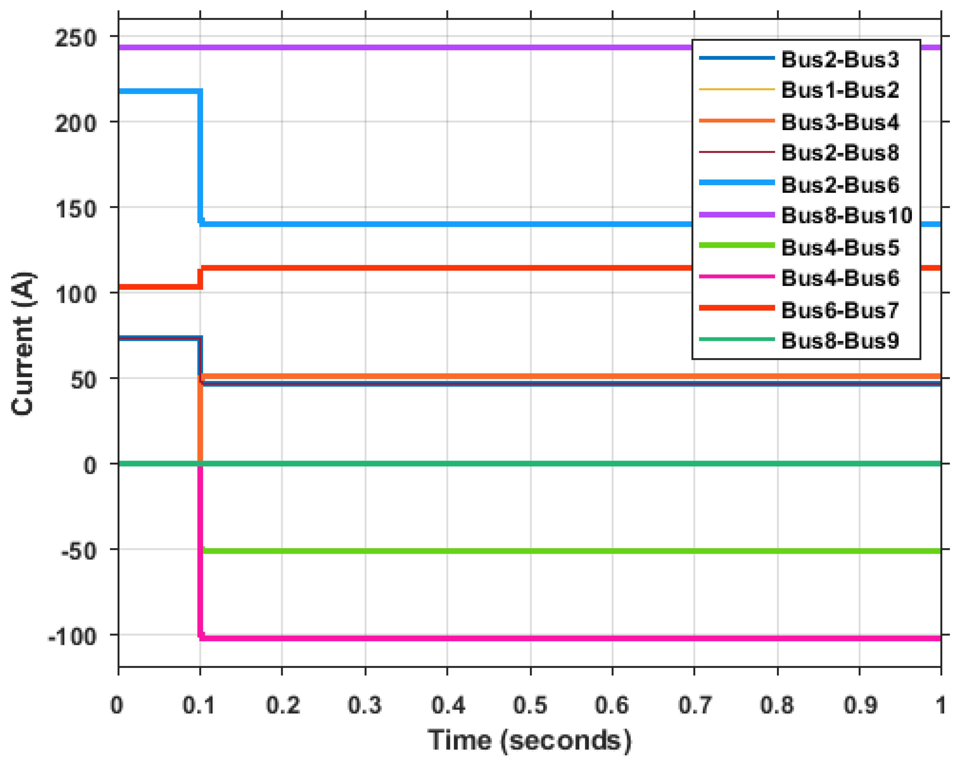
| Branches | Currents before Connecting the DCSOP, A | Currents after Connecting the DCSOP, A |
|---|---|---|
| Bus 1–Bus 2 | 72.5 | 33.3 |
| Bus 2–Bus 3 | 72.5 | 33.3 |
| Bus 3–Bus 4 | 0 | 72.8 |
| Bus 4–Bus 5 | 0 | −72.8 |
| Bus 2–Bus 6 | 217.5 | 100 |
| Bus 6–Bus 7 | 102.6 | 119.4 |
| Bus 2–Bus 8 | 72.5 | 33.3 |
| Bus 8–Bus 9 | 0 | 0 |
| Bus 8–Bus 10 | 242.3 | 242.3 |
| DCSOP | 0 | −145.6 |
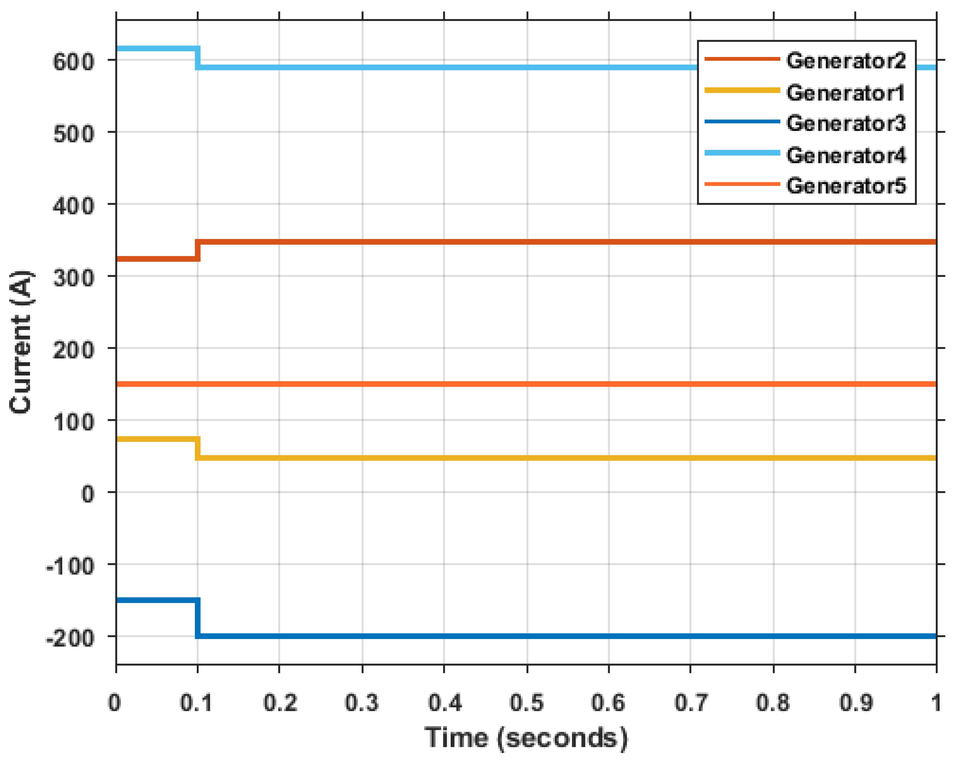
| Generators | Currents before Connecting the DCSOP, A | Currents after Connecting the DCSOP, A |
|---|---|---|
| Generator 1 | 72.5 | 33.3 |
| Generator 2 | 322.5 | 356.7 |
| Generator 3 | −149.8 | −222.6 |
| Generator 4 | 615.5 | 576.4 |
| Generator 5 | 149.8 | 149.8 |
| Branches | Currents with NOP, A | Currents with a Normal Conductor Closing the NOP, A |
|---|---|---|
| Bus 1–Bus 2 | 72.5 | 37.9 |
| Bus 2–Bus 3 | 72.5 | 37.9 |
| Bus 3–Bus 4 | 0 | 67.6 |
| Bus 4–Bus 5 | 0 | −67.6 |
| Bus 4–Bus 6 | 0 | −135.2 |
| Bus 2–Bus 6 | 217.5 | 113.8 |
| Bus 6–Bus 7 | 102.6 | 117.4 |
| Bus 2–Bus 8 | 72.5 | 37.9 |
| Bus 8–Bus 9 | 0 | 0 |
| Bus 8–Bus 10 | 242.3 | 242.3 |
| Generators | Currents with NOP, A | Currents with a Normal Conductor Closing the NOP, A |
|---|---|---|
| Generator 1 | 72.5 | 38 |
| Generator 2 | 322.5 | 355.5 |
| Generator 3 | −149.8 | −217.4 |
| Generator 4 | 615.5 | 581 |
| Generator 5 | 149.8 | 149.8 |
| CAIDI | % Improvement | SAIDI | % Improvement | |
|---|---|---|---|---|
| Case R.1 | 1.269 | - | 1.0497 | - |
| Case R.2 | 0.961 | 24.3% | 0.964 | 8.1% |
| Case R.3 | 0.964 | 24.0% | 0.7461 | 28.9% |
| Case R.4 | 0.658 | 48.1% | 0.656 | 37.5% |
Publisher’s Note: MDPI stays neutral with regard to jurisdictional claims in published maps and institutional affiliations. |
© 2022 by the authors. Licensee MDPI, Basel, Switzerland. This article is an open access article distributed under the terms and conditions of the Creative Commons Attribution (CC BY) license (https://creativecommons.org/licenses/by/4.0/).
Share and Cite
Ramadan, H.A.; Skarvelis-Kazakos, S. DC Soft Open Points for Resilient and Reconfigurable DC Distribution Networks. Energies 2022, 15, 5967. https://doi.org/10.3390/en15165967
Ramadan HA, Skarvelis-Kazakos S. DC Soft Open Points for Resilient and Reconfigurable DC Distribution Networks. Energies. 2022; 15(16):5967. https://doi.org/10.3390/en15165967
Chicago/Turabian StyleRamadan, Husam A., and Spyros Skarvelis-Kazakos. 2022. "DC Soft Open Points for Resilient and Reconfigurable DC Distribution Networks" Energies 15, no. 16: 5967. https://doi.org/10.3390/en15165967
APA StyleRamadan, H. A., & Skarvelis-Kazakos, S. (2022). DC Soft Open Points for Resilient and Reconfigurable DC Distribution Networks. Energies, 15(16), 5967. https://doi.org/10.3390/en15165967