Article

An Electromagnetic Wind Energy Harvester Based on Rotational Magnet Pole-Pairs for Autonomous IoT Applications

1
Department of Electrical and Electronic Engineering, Islamic University, Kushtia 7003, Bangladesh
2
Department of Electronic Engineering, Kwangwoon University, Seoul 01897, Korea
3
Interdisciplinary Microsystems Group, University of Florida, Gainesville, FL 32601, USA
*
Author to whom correspondence should be addressed.
Energies 2022, 15(15), 5725; https://doi.org/10.3390/en15155725
Submission received: 15 June 2022 / Revised: 27 July 2022 / Accepted: 4 August 2022 / Published: 6 August 2022
(This article belongs to the Special Issue Low-Frequency Vibration-Based Electromagnetic Energy Harvesters)

Abstract

:
In this paper, we report a wind energy harvesting system for Internet of Things (IoT)-based environment monitoring (e.g., temperature and humidity, etc.) for potential agricultural applications. A wind-driven electromagnetic energy harvester using rotational magnet pole-pairs (rotor) with a back-iron shield was designed, analyzed, fabricated, and characterized. Our analysis (via finite element method magnetic simulations) shows that a back-iron shield enhances the magnetic flux density on the front side of a rotor where the series connected coils interact and convert the captured mechanical energy (wind energy) into electrical energy by means of electromagnetic induction. A prototype energy harvester was fabricated and tested under various wind speeds. A custom power management circuit was also designed, manufactured, and successfully implemented in real-time environmental monitoring. The experimental results show that the harvester can generate a maximum average power of 1.02 mW and maximum power efficiency of 73% (with power management circuit) while operated at 4.5 m/s wind speed. The system-level demonstration shows that this wind-driven energy harvesting system is capable of powering a commercial wireless sensor that transmits temperature and humidity data to a smartphone for more than 200 min after charging its battery for only 10 min. The experimental results indicate that the proposed wind-driven energy harvesting system can potentially be implemented in energetically autonomous IoT for smart agriculture applications.

1. Introduction

With the tremendous progress of microelectronic industries over the past several decades, uses of microelectronic devices and sensors are being increasing widely used in different fields, such as wireless sensor networks (WSNs) and the Internet of Things (IoT), to collect various information and to monitor environment conditions [1,2]. Their uses in smart-farming/agriculture are also increasing day by day. Recently, the world government summit launched a report entitled ‘Agriculture 4.0—The Future of Farming Technology’ to increase the production of food (by expanding smart technologies in agriculture) by 70% by 2050 [3]. Supplying electrical power to WSNs and IoT devices in remote areas is a critical challenge for the development of smart technologies in agriculture. The required operational power for these devices ranges from a few microwatts to several watt levels which are typically powered by conventional electrochemical batteries [4]. However, these batteries have a short operational lifespan and are sometimes difficult to replace [5,6]. Additionally, the disposal of hazardous materials in most of those batteries exerts a potential threat to the environment [7]. Therefore, there is an increasing demand for alternative power sources to continuously supply clean and sustainable energy to these WSNs and IoT devices. Kinetic energy in the form of vibration/motion [8], thermal energy in the form of heat [9], solar energy in the form of light [10], etc., are promising alternatives and can be harvested to meet these needs.
Wind energy, as a kind of widespread kinetic energy, can be harvested to generate electricity for powering WSNs and IoT devices located in remote areas [11]. Complex designs, large volumes, high manufacturing and maintenance costs, and high electromagnetic interferences and drag ratios of conventional wind turbines mostly restrict their application to remotely operated WSNs and IoT devices [12]. Their turbines cannot be driven simply by smaller wind speed; however, a wind turbine that starts turning at a small wind speed (cut-in wind speed) and can produce a useful amount of power is highly desired. Therefore, many researchers are interested in miniaturizing wind-based generators for self-powered WSNs and IoT devices in practical applications.
Over the years, different wind energy harvesting methods have been reported such as fluttering, galloping, vortex-induced vibration, and wake-galloping [13,14,15,16]. Each method converts wind energy into the vibration of an elastic structure which is then converted to electrical energy via electromechanical transducers, e.g., electromagnetic, piezoelectric, and triboelectric. For instance, Quy et al. [17] reported a fluid-induced flutter-powered energy harvester by fabricating two electromagnetic micro-generators while testing in both a wind tunnel and real conditions. A theoretical model based on galloping oscillations was developed and experimentally validated with an electromagnetic energy harvester by Ali et al. [18]. Kumar et al. [19] investigated the vortex-induced vibration of a flexible cantilevered flapper placed in the wake of a rigid circular cylinder to harvest wind energy by piezoelectric means. Usman et al. [20] recently reported a reliable method of harnessing naturally available wind energy by a wake-galloping-based novel piezoelectric energy harvester. Note that the above-mentioned wind energy harvesters were based on vibration/motion; however, rotational wind energy harvesters using rotor-based transducers have also been reported [21,22,23,24,25].
Yang et al. [26] reported a rotational piezoelectric wind energy harvester by utilizing ball-impact-induced resonance in order to enhance the mechanical (in this case wind) to electrical energy transformation. A low-speed broadband rotational energy harvesting methodology using magnetically coupled piezoelectric beams and frequency up-conversion was investigated by Fu and Yeatman [27] and demonstrated a wind energy harvester with a self-adjusting function for increased air speed range [28]. Han et al. [29] developed, studied, and tested three-dimensional (3D)-printed rotational air-driven electromagnetic energy harvesters with simple structures, low construction costs, and fast prototyping. Wu and Lee [30] introduced a miniature windmill-structured electromagnetic energy harvester for the wireless monitoring of forest fires by analyzing various blade types to achieve the highest aerodynamic efficiency for this windmill-structure. Ahmed et al. [31] introduced a farm structure concept that included wind-driven triboelectric nanogenerators for large-scale energy harvesting based on the freestanding mode between two disks with patterns of micro-sized circular sectors. Recently, Wang et al. [32] developed a gravity triboelectric nanogenerator to convert wind energy into gravitational potential energy that was then transformed into steady electric energy. Besides these single-transducer-based wind energy harvesting approaches, researchers also reported multi-transducer-based approaches by hybridizing piezoelectric and electromagnetic [33], piezoelectric and triboelectric [34], electromagnetic and triboelectric [35], and even piezoelectric, electromagnetic, and triboelectric transducers [25].
Till now, most rotational wind energy harvesters have been realized based on piezoelectric and triboelectric effects. According to our knowledge, a lot of research has been reported based on vibrational electromagnetic wind energy harvesting, but no research has been reported by using rotational electromagnetic wind energy harvesting in recent years. In 2006, Weimer et al. [28] presented remote-area rotational electromagnetic wind energy harvesting for low-power autonomous sensors, with a focus on an anemometer-based solution. Recently, rotational hybridized wind energy harvesters have become of interest where an electromagnetic effect is combined with other energy harvesting effects (piezoelectric and triboelectric); however, these require complex power management electronics for practical applications [25]. Nevertheless, rotational electromagnetic energy harvesting is a promising method for wind energy harvesting because of its simple design and large output power, low maintenance cost, and the fact that it does not rely on breakthroughs of materials, generates a large harvesting current, is suitable for a large number of low-frequency vibrations, and offers stable performance for long time periods.
In this work, we demonstrated a magnetic pole-pair-based electromagnetic rotational wind energy harvester to harvest energy from the ambient environment efficiently. Here, an array of magnetic pole-pairs work as a rotor and a back-iron shield is used on one side of the rotor to increase the magnetic field density on the other side where an array of series-connected coils is placed. Finite element magnetic method (FEMM) simulations were performed to determine the magnetic fields and to optimize the design. Subsequently, a prototype device was fabricated and characterized. It generates 1.02 mW average power from 4.5 ms−2 wind speed with an optimum load resistance of 200 Ω. A custom-designed power management circuit with a power conversion efficiency of ~ 70% was manufactured and utilized for a system-level demonstration of the energy harvester. In this case, a self-powered wireless environmental (temperature and humidity) monitoring system was demonstrated for application in smart agriculture that exhibits the capability and application scenario for wind energy harvesting.

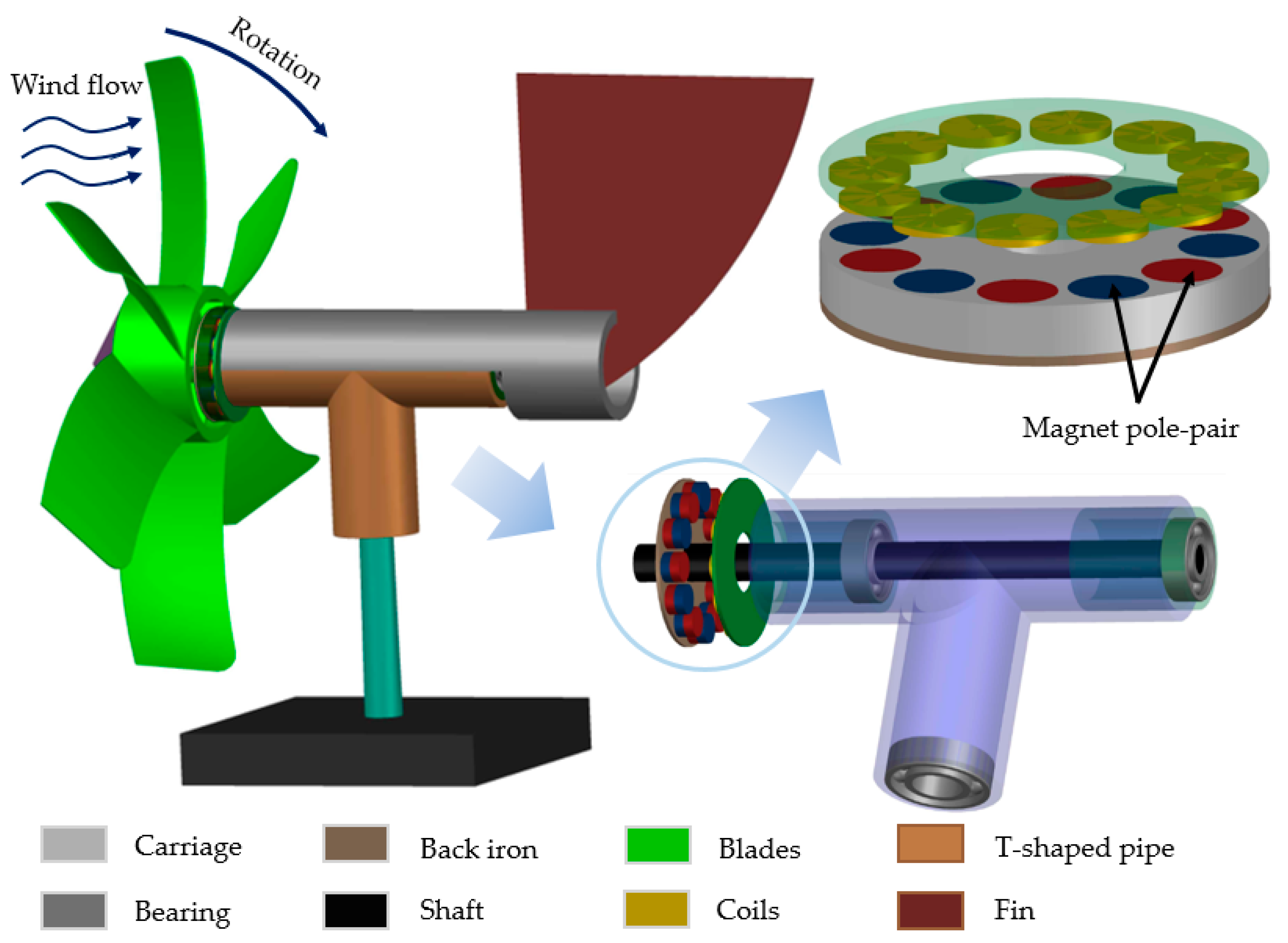
2. Harvester Structure and Its Working Principle

To convert the wind energy (mechanical energy) coupled by the wind turbine into electrical energy, an electromagnetic transducer was incorporated within the rotor. The schematic structure of the proposed electromagnetic wind energy harvester (EMWEH) using magnet pole-pairs is depicted in Figure 1. It consists of a rotating disk-based structure containing six NdFeB (N52) magnet pole-pairs with a back-iron shield and twelve series-connected copper coils fixed in the lower part of the housing by using a printed circuit board (PCB). The back-iron shield on the rotor increases the magnetic flux densities on the opposite side where the coils are placed. The harvester also contains a fin at the back of the housing structure that acts as a direction controller to keep the turbine against the direction of wind flow. The entire structure is attached to a support stand with a bearing. By the influence of external wind energy (coupled via the turbine blades), the rotor (i.e., the magnet pole-pairs) starts rotating, and the relative motion between the magnet pole-pairs and the series-connected coils creates a change in the magnetic flux densities which, in turn, generates electromotive force (emf) voltage across the coil terminals by Faraday’s law of electromagnetic induction. When a load resistance is connected, current flows through the circuit and power is delivered to the load.
The mechanical system of the proposed EMWEH represents a rotational single-degree-of-freedom (SDOF) system excited by wind energy where the rotor is aligned parallel to the wind turbine using a shaft and rotates in accordance with the wind turbine. Therefore, the rotation speed of the rotor is the same as the turbine rotation speed (both are rotating together). The aerodynamic model of the turbine/rotor under no-load electric condition is then given by [36].
J θ ¨ + c θ ˙ = P i n θ ˙
where J is the inertia of the wind turbine/rotor and c is the mechanical damping coefficient. θ ˙ and θ ¨ are the mechanical angular velocity and angular acceleration of the turbine/rotor, respectively. P i n is the input mechanical power produced by the turbine blades due to the moving air, which is given by [36].
P i n = 1 2 ρ A v 3 χ
where ρ is the density of air, A is the area swept by the turbine blades, v is the wind speed, and χ is the power coefficient of the turbine/rotor. It is to be noted that the theoretical maximum value of χ is 0.59 for high-speed, two-blade turbines, and between 0.2 and 0.4 for slow speed turbines with more blades [36]. Now, the amount of emf voltage induced in the series coils due to the relative motion between the magnet pole-pairs embedded in the rotor and the coils is:
V e m f = N d d t [   B · d A ] = N B l θ ˙
where N is the total number of coil turns,   B · d A indicates the magnetic flux through the differential element area d A of the magnet-coil assembly, B is the magnetic flux density, and l is the coil length across the magnetic flux lines. The relative angular velocity θ ˙ between the magnet pole-pairs (i.e., the rotor) and the coils can be determined by numerically solving the governing equation of the turbine/rotor motion driven by the wind, presented in (1). Finally, the amount of power delivered to a resistive load R l connected to the output ports of the EMWEH (neglecting the coil inductance as its impedance is significantly smaller at low frequencies, i.e., below 1 kHz) is:
P = 1 T 0 T ( V e m f ) 2 R l d t
In order to optimize the back-iron shield thickness to maximize the magnetic flux density of the magnet pole-pairs, we performed a 2D axis-symmetric simulation using finite element method magnetic (FEMM) software, as illustrated in Figure 2. Figure 2a shows the distribution of the magnetic flux lines of a portion of the magnet pole-pairs with no back-iron shield. In this case, the average flux density at 1 mm distance (where the coil is located) is ~0.51 T. As we see in Figure 2b, this value is increased by 15% when a 1 mm thick back-iron shield is attached behind the magnet pole-pairs. Figure 2c shows how the value of average flux density (at 1 mm distance from the magnet) changes with the change in the thickness of the back-iron shield. The plot indicates that the average flux density increases with the thickness of up to 1.1 mm and then saturates. Since the increased thickness of the back-iron shield can increase the mass of the whole prototype, therefore, a 1 mm thick back-iron shield was selected that gave a near-maximum flux density value. To maximize the flux linkage through all the layers of the coil windings, the smallest possible air gap (<1 mm) between the magnet pole-pairs and the coil array was maintained during prototype assembly (discussed in the next section).

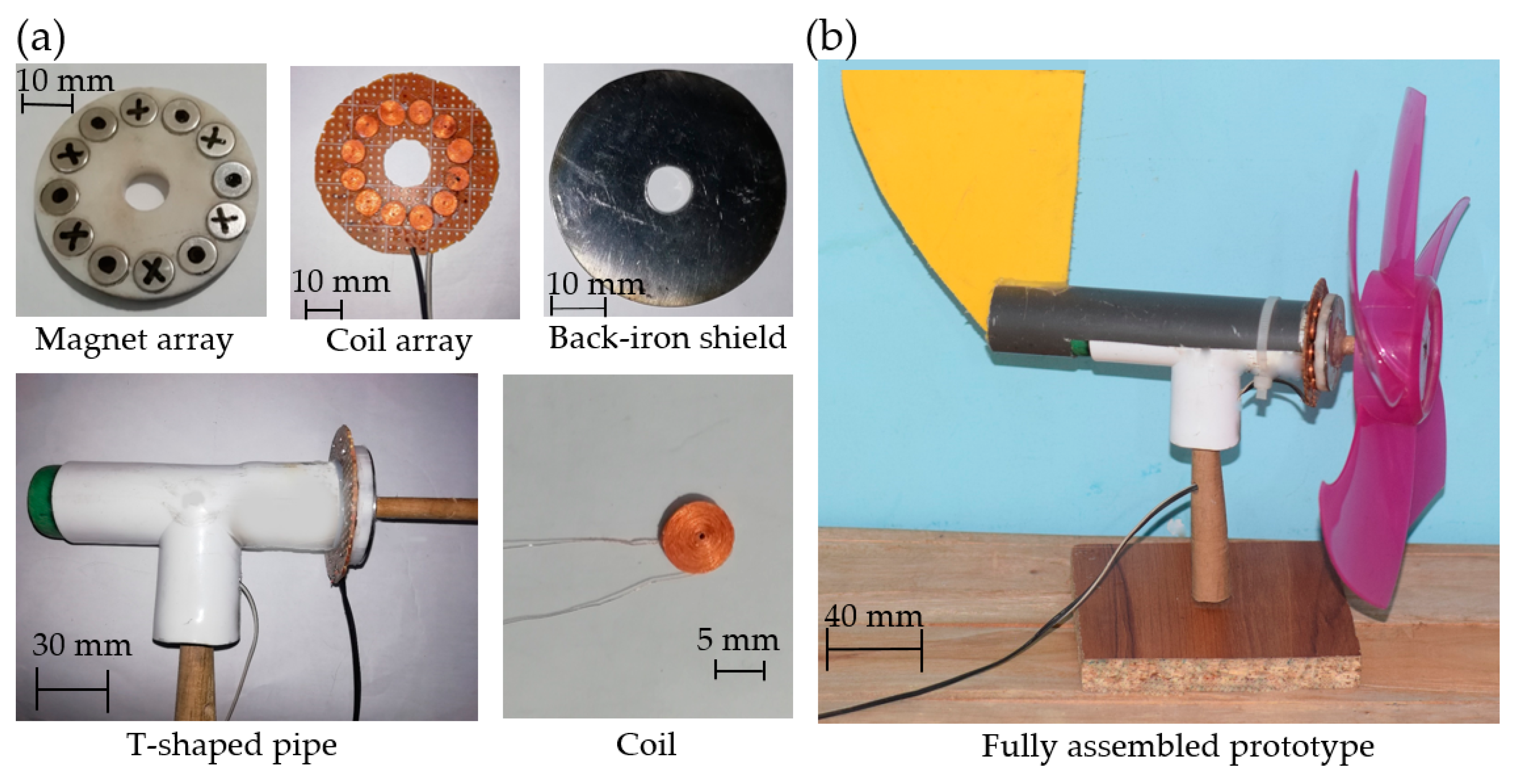
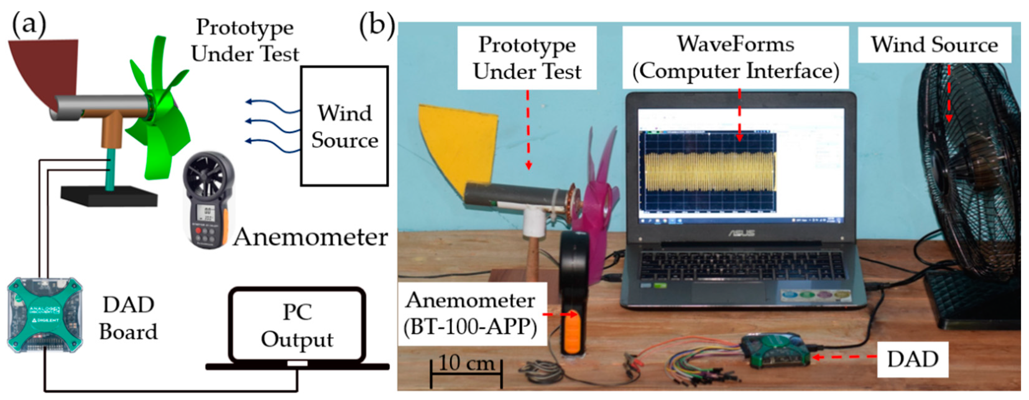
3. Prototype and Experimental Setup

We fabricated, characterized, and demonstrated a prototype of the proposed EMWEH to drive a self-powered wireless smart agriculture monitoring sensor (temperature and humidity). The best suitable magnetic structure was chosen using FEMM analysis. Figure 3a shows the components of the EMWEH before assembly. It has a rotating disk-based structure (rotor) which is composed of a 3D-printed magnet-carriage to hold six NdFeB (N52) magnet pole-pairs and a back-iron shield (made of 1010 stainless steel) glued behind the magnet pole-pairs of the rotor. The magnets were unwaveringly attached to the circular carriage. Twelve self-supported coils (350 turns each) were wound using 44 AWG laminated copper wire and connected in series with the help of a PCB interconnect that worked as the coil carriage. It is to be noted that the magnet pole-pairs placed in the rotor had an opposite polarity; that is why the adjacent coils were placed in anti-mount orientations. The coil carriage was fixed to one side of a T-shaped pipe. To maintain the rotation of the turbine smooth, a shaft made of wood (Ø8 × 150 mm) was installed using two front-facing bearings mounted inside the pipe. The magnet carriage was fixed with the shaft, perfectly aligned with the coil carriage, and the turbine was attached to the shaft-end (near the magnet carriage). As wind can flow from any direction, a fin structure was integrated at the end of the T-shape pipe (opposite side of the turbine) that acted as a direction controller in order to align the EMWEH across the wind flow direction. One more bearing was installed at the bottom leg of the T-shaped pipe to ensure the rotation of the entire device for alignment with the wind flow direction. Finally, the fabricated EMWEH was assembled on a portable base stand, as shown in Figure 3b. Focusing on practical applications, the transducer of the EMWEH was enclosed by a thin plastic frame and sealed with commercial glue to protect the device from external environmental hazards such as dust, water splashes, and strong wind. The geometric parameter of each components used to fabricate the EMWEH prototype is given in Table 1.
The fabricated and assembled EMWEH was first characterized at various wind speeds in a laboratory setup. Figure 4 shows the schematic and photograph of the experimental setup. The wind was generated and controlled by a traditional electric fan. The wind speed could be continuously varied from 0 to 4.5 m/s, and the speed was measured using a digital anemometer (BT-100-APP). To observe and record the output performance of the EMWEH, the transducer output was connected to a USB-powered Digilent Analog Discovery 2 (DAD) data acquisition system. A computer interface was used to record and store the measured data from the DAD. Later, the system-level performance of the EMWEH was demonstrated by using a custom power management circuit (PMC) and low-power sensor electronics, which is discussed in the following section.

4. Results and Discussion

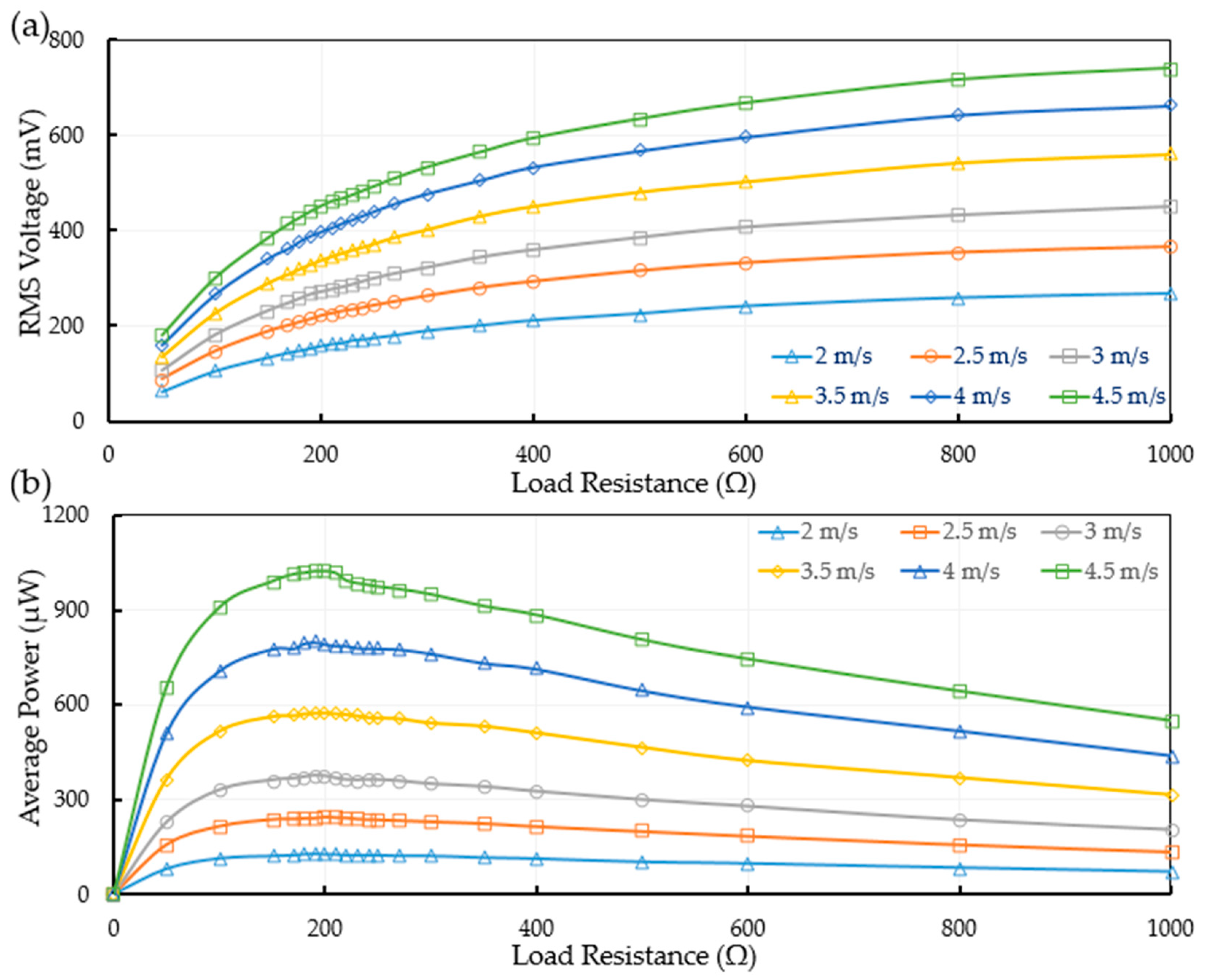
4.1. Transducer Outputs

The voltages generated by the EMWEH prototype under various input (wind speed) and load conditions were observed and recorded for further analysis. At first, we studied the variation of open-circuit voltage outputs of the harvester at different wind speeds ranging from 2 to 4.5 m/s, as shown in Figure 5a. As seen in the figure, the open-circuit voltage is proportional to the wind speed that increases (peak-to-peak voltage from 0.89 V to 2.75 V) linearly with the increase in the wind speed. Figure 5b illustrates the time histories (waveforms) of the generated voltage for wind speeds from 2 to 4.5 m/s. It is clear that the amplitude of the generated voltage increases as the relative velocity between the magnet pole-pairs and the coils (in other words, the rotational frequency) is increased at higher wind speeds. More peaks are observed as the wind speed increases which, in turn, increases the energy conversion. We determined the frequency of the generated voltage waveforms by using the First Fourier Transform (FFT). The dominant response frequency increases from 30 Hz to 87 Hz when the wind speed increases from 2 to 4.5 m/s.
To examine the optimal performance, the rms (root mean square) voltage and the average power outputs of the EMWEH prototype were measured under various load resistances swept from 50 Ω to 1000 Ω with variable wind speeds ranging from 2 to 4.5 m/s. The rms voltages across various load resistances and the corresponding average power delivered are shown in Figure 6. From the plots, the optimum load resistance is found to be 200 Ω, which closely matches the resistance of the series connected coil resistance (204 Ω) of the series-connected coils of the transducer. The average power P a v g was calculated from the experimentally obtained rms voltage V r m s and the corresponding load resistance R l by using P a v g = V r m s 2 / R l . Both the rms voltage across optimum load resistances and the corresponding power values were increased (from 153 mV to 452 mV and from 126 µW to 1.02 mW, respectively) when the wind speed was increased from 2 to 4.5 m/s.

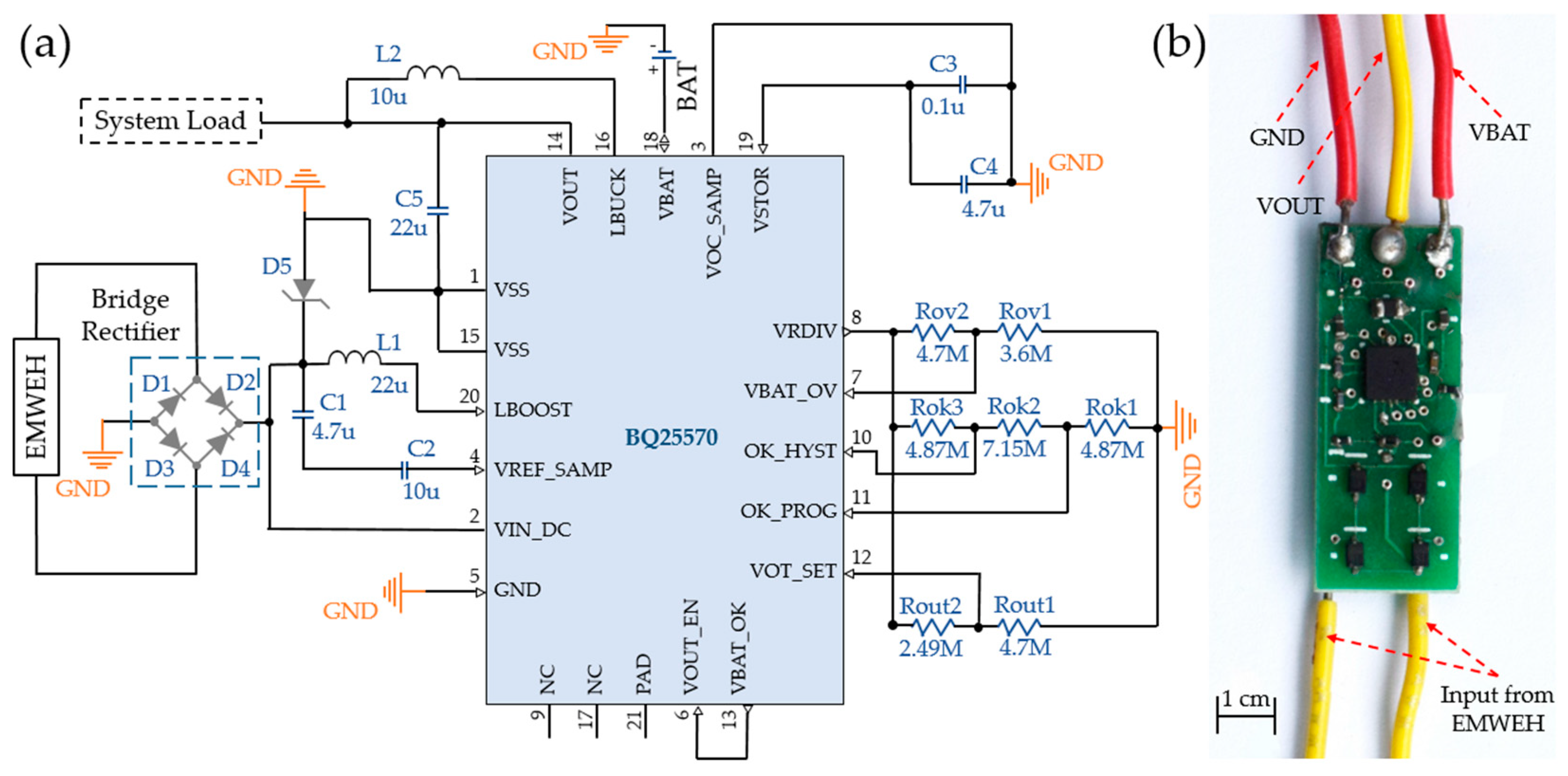
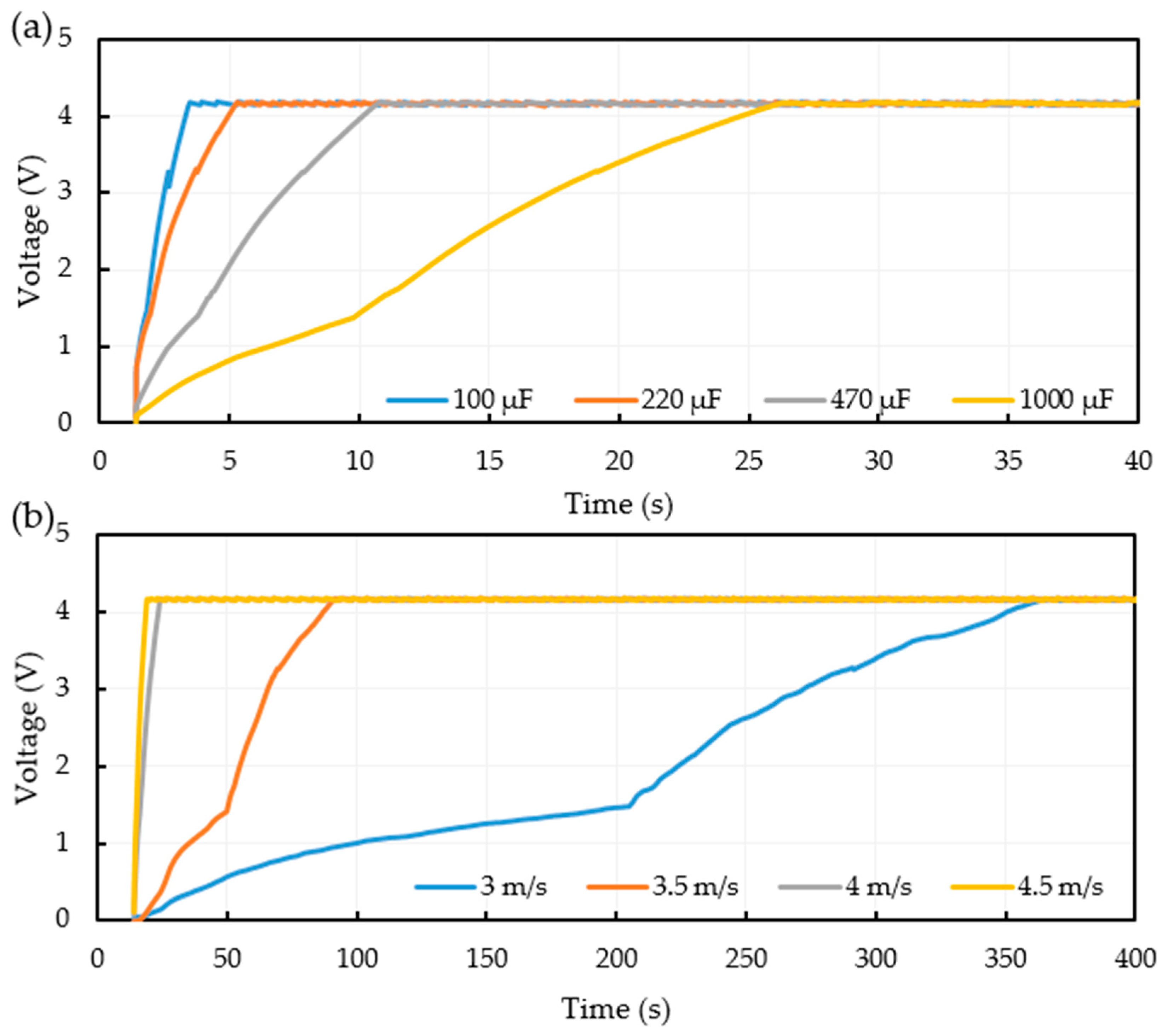
4.2. Power Management Circuit (PMC)

The EMWEH prototype generates a sinusoidal open-circuit voltage (peak to peak) on the scale of a few volts that changes with the wind speed. In order to supply a constant voltage to power any electronic load (e.g., WSN, IoT sensor, etc.), the ac output voltage waveform needs to be rectified and regulated to a stable dc voltage for direct use or to store in a secondary storage unit (e.g., a battery or super-capacitor). For that, we designed and manufactured a custom PMC on a compact two-layer printed circuit board (PCB), as shown in Figure 7. In the initial stage, a full-wave bridge rectifier with four Schottky diodes (PMEG2020AEA) converts the ac output of the EMWEH into a dc output. A BQ25570 nano-power boost charger and buck converter used in the second stage accepts the rectified dc voltage and stores the energy on an external storage element at a programmable voltage level. The buck converter of the BQ chip also regulates the voltage output to an external load. The programmed voltage for the storage unit was set to 4.2 V (standard for charging a lithium polymer (LiPo) battery [37]), and the output voltage was fixed at 3.4 V (required to operate the WSN).
The charging capability was investigated by connecting a capacitor at the battery terminals of the PMC, while the output of the EMWEH was supplied to the input of the PMC. As shown in Figure 8, the tests were performed with two different conditions: (i) vary the capacitance value by keeping the wind speed fixed at 4.5 m/s and (ii) vary the wind speed by keeping the capacitance fixed at 1000 µF. In both cases, no load was connected to the load terminals. As seen from the plots, the voltage curves across the capacitor are dependent on the performance of the BQ25570 chip. Due to the cold start process of the BQ25570 chip, initially (up to 1.5 V), the voltage curve was growing slowly. After the capacitor voltage reached 1.5 V, the voltage grew relatively faster. There was a programmed starting point of 3.3 V after which the PMC started outputting 3.4 V to the load terminals. Finally, the capacitor voltage reached 4.2 V and began cyclically charging and discharging around it.
The next characterization parameter of interest was the “efficiency” of the PMC. The efficiency η is the ratio of maximum DC power P D C measured from the PMC to the maximum average ac power P a v g the EMWEH could be delivered to its optimum load. In this case, DC voltages V D C across different resistive loads R L (swept from 1 kΩ to 60 kΩ) connected to the load terminals of the PMC were measured, while the EMWEH was operated at various wind speeds. The DC power values were then calculated by using P D C = V D C 2 / R L . Figure 9 shows the DC power versus resistive load for various wind speeds. The results show that the calculated maximum DC power values increase from 277 μW to 737 μW with the increase in the wind speed from 3 m/s to 4.5 m/s, respectively. However, the values of the optimum load resistance for various wind speeds are different and decrease with the increase in the wind speed. These numbers are in the range of tens of kΩ which are very much different to the optimum load resistance (200 Ω) of the EMWEH itself. This is not unexpected because when the wind speed increases, the current flow through the PMC also increases which changes (reduce) the internal impedance of the PMC. Now, the calculated power conversion efficiency of the PMC lies around 70% for the EMWEH operating under various wind speeds, as summarized in Table 2.

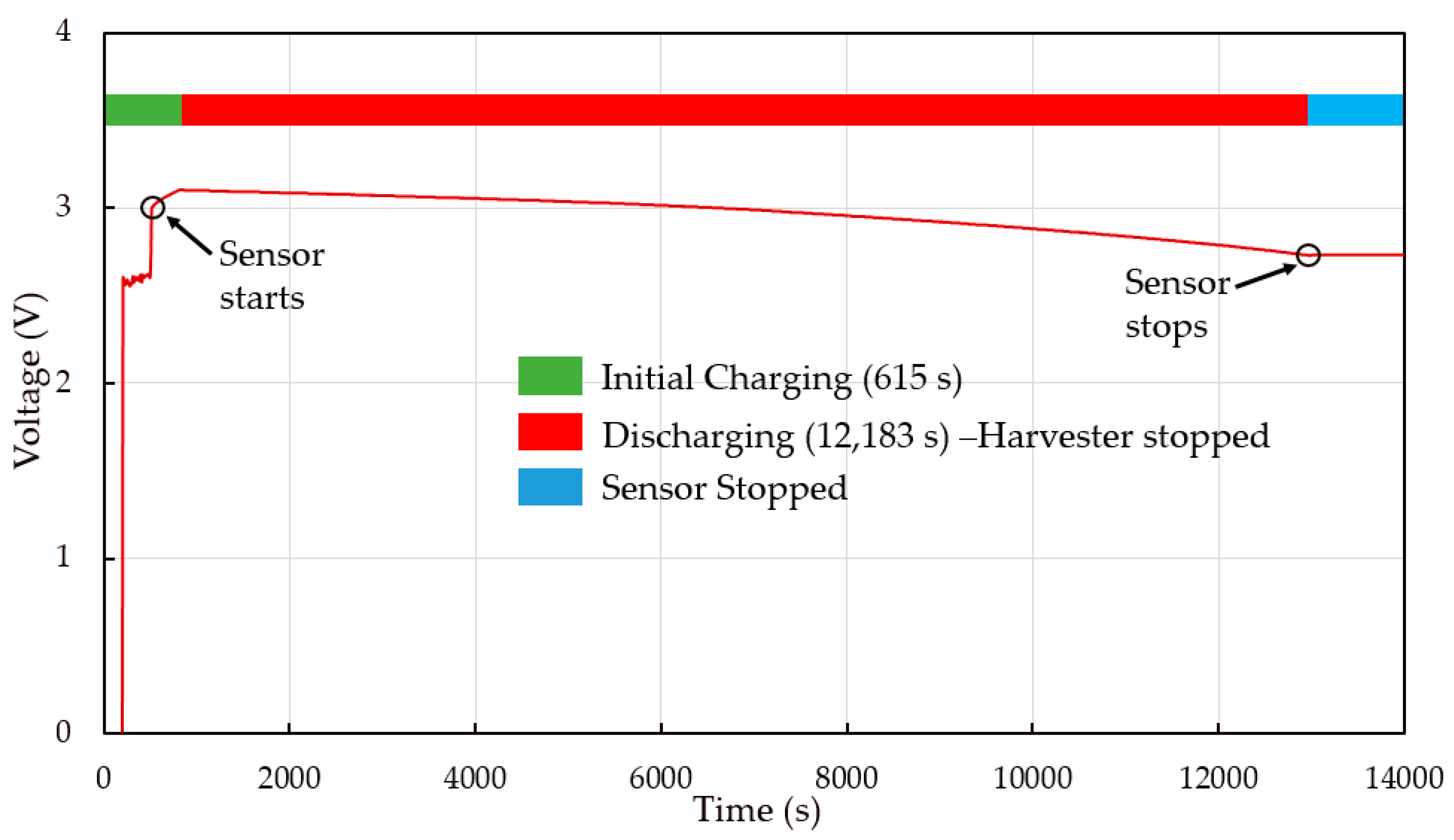
4.3. System-Level Demonstration

To demonstrate the application of the proposed EMWEH, an autonomous wireless smart-agriculture monitoring (AWSAM) system using wind energy was developed, which can transmit signals to a smartphone interface via Bluetooth. The complete architecture of the AWSAM system together with the EMWEH is presented in Figure 10a. The custom-developed PMC was used to maintain a 3.4 V DC voltage to power up a low-power wireless sensor devices (an environment sensor, a microcontroller unit, and a Bluetooth module). To monitor the environmental conditions, a commercial environmental sensor (Mi Temperature and Humidity Monitor 2) was used as a physical sensor node which can display (it has a 1.5-inch LCD display) and transmits the results to a remote device (e.g., smartphone) via Bluetooth. For better crop yielding from remote areas, smart-agriculture has become an utmost important tool. A conceptual illustration of the real-time monitoring of the environment for smart agriculture using a smartphone interface is shown in Figure 10b. The experimental setup of the AWSAM system with the EMWEH, the PMC, and the wireless sensor devices is depicted in Figure 10c. Using the PMC, the generated electrical energy from EMWEH is continuously stored in the storage element (20 mAh LiPo battery) until the power necessary to operate the wireless sensor devices (connected to the load terminal of the PMC) is obtained. Figure 11 illustrates the real-time charging and discharging characteristics of the battery during the operation of the wireless sensor devices. It was observed that the wireless sensor devices started running when the voltage level reached 3 V after charging the battery for 5.27 min and kept running as long as the EMWEH was operating under a wind speed of 4.5 m/s. When the battery was charged up to ~3.1 V in about 10 min, the EMWEH was turned off. The wireless sensor devices kept running and transmitting the data for more than 200 min when the battery voltage dropped to 2.7 V. Note that, to connect the wireless sensor devices with a smartphone via Bluetooth, it required some extra power (nearly 3.6 mW) that was supplied from the energy stored in the battery beforehand. However, once the sensor was connected to the smartphone, it consumed very low power to sense and transmit.

5. Conclusions

In this article, we designed, fabricated, and successfully demonstrated a magnetic pole-pair-based electromagnetic rotational wind energy harvester to harvest energy from the ambient environment for wireless sensor applications. The electromagnetic transducer of the harvester was optimized to maximize the magnetic flux linkage between the magnet pole-pairs and series-connected coils for higher performance. A fabricated prototype harvester was tested in the laboratory setup under controlled wind flow conditions. At 4.5 m/s wind speed, it can generate 2.75 V peak-to-peak open-circuit voltage. At the same operating condition, it is capable of delivering a maximum 1.02 mW average AC power to an optimum load resistance of 200 Ω and a maximum 737 µW DC power to a 40 kΩ resistive load via a custom-designed power management circuit. The power conversion efficiency of the power management circuit is around 70%. Combined with the PMC, the proposed wind energy harvester is capable of powering a remote smart-agricultural monitoring system. A real-time wireless environmental monitoring system enabled by the proposed wind-driven energy harvester was demonstrated that continuously transmits temperature and humidity data to a smartphone. Table 3 summarizes the performance comparison of various similar small-scale wind energy harvesters, and the proposed device offers the highest power density/normalized power density per transducer swept area. It also has a simple design and is easy to fabricate with lightweight and inexpensive materials. In addition to potential autonomous agricultural monitoring applications, the proposed energy harvesting system can be used for traffic monitoring, forest fire detection, subway tunnel monitoring, etc. However, there is room for further improvement of the harvester performance within the constrained volume by optimizing the turbine structure as well as the transducer unit (to maximize the wind coupling and power generation, respectively) which will be reported in future work.

Author Contributions

Conceptualization, S.R. and M.A.H.; methodology, S.R. and M.A.H.; software, S.R.; validation, S.R.; formal analysis, S.R.; investigation, S.R.; resources, S.R., M.A.H., M.S. and M.H.K.; data curation, S.R. and M.A.H.; writing—original draft preparation, S.R.; writing—review and editing, S.R., M.A.H., M.S. and M.H.K.; visualization, S.R.; supervision, M.A.H. and M.H.K.; project administration, M.A.H., M.S. and M.H.K.; funding acquisition, S.R., M.A.H., M.S. and M.H.K. All authors have read and agreed to the published version of the manuscript.

Funding

This work has been supported by the Ministry of Science and Technology, Bangladesh, Financial Year 2019–2020, Special Grants from Science and Technology Program, GO No. 39.00.0000.009.06.024.19/EAS-420-436, dated 12 January 2020.

Institutional Review Board Statement

Not applicable.

Informed Consent Statement

Not applicable.

Data Availability Statement

Not applicable.

Acknowledgments

Special thanks to all members of David P. Arnold’s research group and all other members of the Interdisciplinary Microsystems Group at the University of Florida.

Conflicts of Interest

The authors declare no conflict of interest.

References

  1. Hittinger, E.; Jaramillo, P. Internet of Things: Energy boon or bane. Science 2019, 364, 326–328. [Google Scholar] [CrossRef] [PubMed] [Green Version]
  2. Shaikh, F.K.; Zeadally, S. Energy harvesting in wireless sensor networks: A comprehensive review. Renew. Sustain. Energy Rev. 2016, 55, 1041–1054. [Google Scholar] [CrossRef]
  3. Clercq, M.D.; Vats, A.; Biel, A. Agriculture-4.0: The Future of Farming Technology. Available online: https://www.worldgovernmentsummit.org/api/publications/document?id=95df8ac4-e97c-6578-b2f8-ff0000a7ddb6 (accessed on 1 February 2018).
  4. Truitt, A.; Mahmoodi, S.N. A review on active wind energy harvesting designs. Int. J. Precis. Eng. Manuf. 2013, 14, 1667–1675. [Google Scholar] [CrossRef]
  5. Mateu, L.; Moll, F. Review of energy harvesting techniques and applications for microelectronics. Proc. SPIE 2005, 5837, 359–373. [Google Scholar]
  6. Liu, W.; Chen, J.; Chen, Z.; Liu, K.; Zhou, G.; Sun, Y.; Song, M.S.; Bao, Z.; Cui, Y. Stretchable Lithium-Ion Batteries Enabled by Device-Scaled Wavy Structure and Elastic-Sticky Separator. Adv. Energy Mater. 2017, 7, 1701076. [Google Scholar] [CrossRef]
  7. Mohanty, A.; Parida, S.; Behera, R.K.; Roy, T. Vibration energy harvesting: A review. J. Adv. Dielectr. 2019, 9, 1930001. [Google Scholar] [CrossRef]
  8. Kishore, R.A.; Priya, S. A review on low-grade thermal energy harvesting: Materials, methods and devices. Materials 2018, 11, 1433. [Google Scholar] [CrossRef] [Green Version]
  9. Kannan, N.; Vakeesan, D. Solar energy for future world: A review. Renew. Sustain. Energy Rev. 2016, 62, 1092–1105. [Google Scholar] [CrossRef]
  10. Wang, J.; Geng, L.; Ding, L.; Zhu, H.; Yurchenko, D. The state-of-the-art review on energy harvesting from flow-induced vibrations. Appl. Energy 2020, 267, 114902. [Google Scholar] [CrossRef]
  11. Tummala, A.; Velamati, R.K.; Sinha, D.K.; Indraja, V.; Krishna, V.H. A review on small scale wind turbines. Renew. Sustain. Energy Rev. 2016, 56, 1351–1371. [Google Scholar] [CrossRef]
  12. Bryant, M.; Wolff, E.; Garcia, E. Aeroelastic flutter energy harvester design: The sensitivity of the driving instability to system parameters. Smart Mater. Struct. 2011, 20, 125017. [Google Scholar] [CrossRef]
  13. Hu, G.; Tse, K.T.; Kwok, K.C.S.; Song, J.; Lyu, Y. Aerodynamic modification to a circular cylinder to enhance the piezoelectric wind energy harvesting. Appl. Phys. Lett. 2016, 109, 193902. [Google Scholar] [CrossRef]
  14. Dai, H.L.; Abdelkefi, A.; Yang, Y.; Wang, L. Orientation of bluff body for designing efficient energy harvesters from vortex-induced vibrations. Appl. Phys. Lett. 2016, 108, 053902. [Google Scholar] [CrossRef]
  15. Zhang, C.; Hu, G.; Yurchenko, D.; Lin, P.; Gu, S.; Song, D.; Peng, H.; Wang, J. Machine learning based prediction of piezoelectric energy harvesting from wake galloping. Mech. Syst. Signal Process. 2021, 160, 107876. [Google Scholar] [CrossRef]
  16. Quy, V.D.; Sy, N.V.; Hung, D.T.; Huy, V.Q. Wind tunnel and initial field tests of a micro generator powered by fluid-induced flutter. Energy Sustain. Dev. 2016, 33, 75–83. [Google Scholar]
  17. Ali, M.; Arafa, M.; Elaraby, M. Harvesting energy from galloping oscillations. In Proceedings of the World Congress on Engineering, WCE, London, UK, 3–5 July 2013; Volume III. [Google Scholar]
  18. Kumar, S.K.; Bose, C.; Ali, S.F.; Sarkar, S.; Gupta, S. Investigations on a vortex induced vibration based energy harvester. Appl. Phys. Lett. 2017, 111, 243903. [Google Scholar] [CrossRef]
  19. Usman, M.; Hanif, A.; Kim, I.-H.; Jung, H.-J. Experimental validation of a novel piezoelectric energy harvesting system employing wake galloping phenomenon for a broad wind spectrum. Energy 2018, 153, 882–889. [Google Scholar] [CrossRef]
  20. Howey, D.A.; Bansal, A.; Holmes, A.S. Design and performance of a centimetre-scale shrouded wind turbine for energy harvesting. Smart Mater. Struct. 2011, 20, 085021. [Google Scholar] [CrossRef] [Green Version]
  21. Weimer, M.A.; Paing, T.S.; Zane, R.A. Remote Area Wind Energy Harvesting for Low-Power Autonomous Sensors. In Proceedings of the Power Electronics Specialists Conference, Jeju, Korea, 18–22 June 2006. [Google Scholar]
  22. Silva, A.G.P.; Sobrinho, J.M.B.; Souto, C.R.; Ries, A.; Castro, A.C. Design, modelling and experimental analysis of a piezoelectric wind energy generator for low-power applications. Sens. Actuators A 2021, 317, 112462. [Google Scholar] [CrossRef]
  23. Perez, M.; Boisseau, S.; Geisler, M.; Despesse, G.; Reboud, J.L. A triboelectric wind turbine for small-scale energy harvesting. J. Phys. Conf. Ser. 2016, 773, 012118. [Google Scholar] [CrossRef]
  24. Rahman, M.T.; Salauddin, M.; Maharjan, P.; Rasel, M.S.; Cho, H.; Park, J.Y. Natural wind-driven ultra-compact and highly efficient hybridized nanogenerator for self-sustained wireless environmental monitoring system. Nano Energy 2019, 57, 256–268. [Google Scholar] [CrossRef]
  25. Yang, Y.; Shen, Q.; Jin, J.; Wang, Y.; Qian, W.; Yuan, D. Rotational piezoelectric wind energy harvesting using impact-induced resonance. Appl. Phys. Lett. 2014, 105, 053901. [Google Scholar] [CrossRef]
  26. Fu, H.; Yeatman, E.M. A methodology for low-speed broadband rotational energy harvesting using piezoelectric transduction and frequency up-conversion. Energy 2017, 125, 152–161. [Google Scholar] [CrossRef] [Green Version]
  27. Fu, H.; Yeatman, E.M. A miniaturized piezoelectric turbine with self-regulation for increased air speed range. Appl. Phys. Lett. 2015, 107, 243905. [Google Scholar] [CrossRef] [Green Version]
  28. Han, N.; Zhao, D.; Schluter, J.U.; Goh, E.S.; Zhao, H.; Jin, X. Performance evaluation of 3D printed miniature electromagnetic energy harvesters driven by air flow. Appl. Energy 2016, 178, 672–680. [Google Scholar] [CrossRef]
  29. Wu, W.; Lee, D.-W. An electromagnetic energy harvesting device based on high efficiency windmill structure for wireless forest fire monitoring application. Sens. Actuators A 2014, 219, 73–79. [Google Scholar] [CrossRef]
  30. Ahmed, A.; Hassan, I.; Hedaya, M.; El-Yazid, T.A.; Zu, J.; Wang, Z.L. Farms of triboelectric nanogenerators for harvesting wind energy: A potential approach towards green energy. Nano Energy 2017, 36, 21–29. [Google Scholar] [CrossRef]
  31. Wang, Y.; Yu, X.; Yin, M.; Wang, J.; Gao, Q.; Yu, Y.; Cheng, T.; Wang, Z.L. Gravity triboelectric nanogenerator for the steady harvesting of natural wind energy. Nano Energy 2021, 82, 105740. [Google Scholar] [CrossRef]
  32. Zhao, L.-C.; Zou, H.-X.; Yan, G.; Liu, F.-R.; Tan, T.; Zhang, W.-M.; Peng, Z.-K.; Meng, G. A water-proof magnetically coupled piezoelectric-electromagnetic hybrid wind energy harvester. Appl. Energy 2019, 239, 735–746. [Google Scholar] [CrossRef]
  33. Zhao, C.; Zhang, Q.; Zhang, W.; Du, X.; Zhang, Y.; Gong, S.; Ren, K.; Sun, Q.; Wang, Z.L. Hybrid piezo/triboelectric nanogenerator for highly efficient and stable rotation energy harvesting. Nano Energy 2019, 57, 440–449. [Google Scholar] [CrossRef]
  34. Guo, Y.; Chen, Y.; Ma, J.; Zhu, H.; Cao, X.; Wang, N.; Wang, Z.L. Harvesting wind energy: A hybridized design of pinwheel by coupling triboelectrification and electromagnetic induction effects. Nano Energy 2019, 60, 641–648. [Google Scholar] [CrossRef]
  35. Rezaei-Hosseinabadi, N.; Tabesh, A.; Dehghani, R.; Aghili, A. An efficient piezoelectric windmill topology for energy harvesting from low-speed air flows. IEEE Trans. Ind. Electron. 2015, 62, 3576–3583. [Google Scholar]
  36. Mukund, R.P. Wind and Solar Power Systems–Design, Analysis and Operation; Taylor/Francis: New York, NY, USA, 2006. [Google Scholar]
  37. Kumar, R.V.; Sarakonsri, T. Lithium-Ion Batteries. In High Energy Density Lithium Batteries: Materials, Engineering, Applications, 1st ed.; Aifantis, K.E., Hackney, S.A., Kumar, R.V., Eds.; Wiley-VCH: Hoboken, NJ, USA, 2010; pp. 70–74. [Google Scholar]
  38. Kwon, S.D. A T-shaped piezoelectric cantilever for fluid energy harvesting. Appl. Phys. Lett. 2010, 97, 164102. [Google Scholar] [CrossRef]
  39. Zhang, J.; Fang, Z.; Shu, C.; Zhang, J.; Zhang, Q.; Li, C. A rotational piezoelectric energy harvester for efficient wind energy harvesting. Sens. Actuators A 2017, 262, 123–129. [Google Scholar] [CrossRef]
  40. Iqbal, M.; Khan, F.U. Hybrid vibration and wind energy harvesting using combined piezoelectric and electromagnetic conversion for bridge health monitoring applications. Energy Convers. Manag. 2018, 172, 611–618. [Google Scholar] [CrossRef]
Figure 1. Schematic structure of the proposed electromagnetic wind energy harvester (EMWEH) using magnet pole-pairs.
Energies 15 05725 g001
Figure 2. Finite element analysis of the magnetic structures to determine the magnetic flux densities: (a) without back-iron shield, (b) with a 1 mm-thick back iron-shield, and (c) average flux density vs. metal (back-iron) thickness.
Energies 15 05725 g002
Figure 3. Photographs of the (a) harvester components before assembly and (b) a fully assembled prototype energy harvester.
Energies 15 05725 g003
Figure 4. (a) Schematic of the experimental setup and (b) photograph of the experimental characterization of the EMWEH prototype.
Energies 15 05725 g004
Figure 5. (a) Peak to peak open-circuit voltages and (b) generated voltage waveforms for various wind speeds.
Energies 15 05725 g005
Figure 6. The values of (a) RMS voltage and (b) average power versus load resistances obtained from the EMWEH prototype under various wind speeds.
Energies 15 05725 g006
Figure 7. (a) Circuit diagram and (b) a photograph of a custom power management circuit (PMC).
Energies 15 05725 g007
Figure 8. DC voltages (no load connected) over time (a) across different capacitors at 4.5 m/s wind speed and (b) across a 1000 µF capacitor at different wind speeds.
Energies 15 05725 g008
Figure 9. DC power versus resistive load while the EMWEH was operated at various wind speeds.
Energies 15 05725 g009
Figure 10. (a) Schematic of the system-level demonstration of the EMWEH, (b) conceptual illustration of real-time environmental monitoring of an agricultural field using smartphone, and (c) photograph of the experimental setup for remote environmental monitoring.
Energies 15 05725 g010
Figure 11. Real-time charging and discharging characteristics of the battery during the operation of the wireless sensor devices.
Energies 15 05725 g011
Table 1. Geometric parameter of each component of the EMWEH prototype.
ComponentParameterValue
RotorMagnet dimensionØ8 mm × 5 mm
Carriage dimensionØ44 mm × 6 mm
Back-iron thickness1 mm
CoilCoil inner diameter0.5 mm
Coil outer diameter8 mm
Coil thickness1 mm
Number of turns (each)350
Coil resistance (each)17 Ω
PCB thickness1 mm
BearingInner diameter8 mm
Outer diameter22 mm
Height7 mm
TurbineDiameter230 mm
Number of blades5
Table 2. Summary of maximum AC power, DC power, and power efficiency for different wind speeds.
Parameter3 m/s3.5 m/s4 m/s4.5 m/s
Max. AC power (µW)3755737981022
Max. DC power (µW)277432552737
Max. efficiency (%)73.875.469.272.1
Table 3. Performance comparison among various similar wind energy harvesters.
ReferenceHarvester TypeTransducer TypeWind Speed (ms−1)Transducer Swept Area (cm2)Avg. Power (µW)PD Per Swept Area (µW cm−2)NPD (µW cm−2/ms−1)
Kwon [38]TranslationalPE4.6602504.20.9
Hu [13]TranslationalPE752390.70.12
Zhang [39]RotationalPE76848001.20.17
Iqbal [40]TranslationalEM-PE611.311.410.17
Zhao [32]RotationalEM-PE71101218111.6
Howey [20]RotationalEM485671.7
This workRotationalEM215.212284
3.557237.610.7
4.5102067.114.9
Publisher’s Note: MDPI stays neutral with regard to jurisdictional claims in published maps and institutional affiliations.

