Review

Current CO2 Capture and Storage Trends in Europe in a View of Social Knowledge and Acceptance. A Short Review

by
Nikolaos Koukouzas
1,*,
Marina Christopoulou
1,2,
Panagiota P. Giannakopoulou
2,
Aikaterini Rogkala
2,
Eleni Gianni
1,
Christos Karkalis
1,
Konstantina Pyrgaki
1,
Pavlos Krassakis
1,
Petros Koutsovitis
2,
Dionisios Panagiotaras
3 and
Petros Petrounias
1,2
1
Centre for Research & Technology Hellas (CERTH), Chemical Process & Energy Resources Institute, 57001 Thermi, Greece
2
Section of Earth Materials, Department of Geology, University of Patras, 26504 Patras, Greece
3
Department of Environment, Ionian University, M. Minotou-Giannopoulou 26, Panagoula, 29100 Zakynthos, Greece
*
Author to whom correspondence should be addressed.
Energies 2022, 15(15), 5716; https://doi.org/10.3390/en15155716
Submission received: 30 June 2022 / Revised: 29 July 2022 / Accepted: 3 August 2022 / Published: 5 August 2022
(This article belongs to the Section B3: Carbon Emission and Utilization)

Abstract

:
Carbon dioxide (CO2) has reached a higher level of emissions in the last decades, and as it is widely known, CO2 is responsible for numerous environmental problems, such as climate change. Thus, there is a great need for the application of CO2 capture and storage, as well as of CO2 utilization technologies (CCUS). This review article focuses on summarizing the current CCUS state-of-the-art methods used in Europe. Special emphasis has been given to mineralization methods/technologies, especially in basalts and sandstones, which are considered to be suitable for CO2 mineralization. Furthermore, a questionnaire survey was also carried out in order to investigate how informed about CO2 issues European citizens are, as well as whether their background is relative to their positive or negative opinion about the establishment of CCUS technologies in their countries. In addition, social acceptance by the community requires contact with citizens and stakeholders, as well as ensuring mutual trust through open communication and the opportunity to participate as early as possible in the development of actions and projects related to CO2 capture and storage, at all appropriate levels of government internationally, as citizens need to understand the benefits from such new technologies, from the local to the international level.

1. State of the Art

Carbon dioxide (CO2) is considered the main greenhouse gas emission enhanced by human activities [1]. In 2019, CO2, CH4, and N2O reached higher levels than during the last 800,000 years, while CO2 measured 409.9 ppm. In particular, the highest average concentration of carbon dioxide over Europe reached 429 ppm during the last six-month period of 2021 (Figure 1).
In addition, over the past 60 million years, periods with significantly higher CO2 concentrations in comparison with the current state have been detected, with the only difference being that the increasing rate of CO2 is at least 10 times faster during 1900 to 2019 compared to any other period of the last 800,000 years [2].
The high CO2 release into the atmosphere intensifies climatic changes [3] related to other environmental problems, such as the acidification of the oceans [4]. During recent decades, almost 80% of the world’s energy consumption per year, which is more than 500 exajoules, was provided by fossil fuels [5]. Due to the economic development and growth of the world population, the global energy consumption may double in future years. Despite the decrease in the burning of fossil fuels and their substitution by renewable energies, sequestration of CO2 is mandatory for the purposes of resuming the use of fossil fuels and the avoidance of CO2 emissions in the atmosphere. Those procedures involve the capture of this gas at specific designed industrial sites, its transport, and final permanent underground storage in ideal geological formations. Potential risks, such as CO2 leakage, geological disasters, and contamination of underground water, must be taken under consideration.
CO2 capture and separation processes are considered expensive procedures. There are three main technology options to capture CO2 from fossil fuel power generation plants [6], namely: (i) post-combustion (CO2 is separated from the flue gas); (ii) oxy-fuel combustion (uses nearly pure oxygen for the combustion of fuel, and CO2 is then removed from the generated gases, formed principally from water vapor and CO2); and (iii) pre-combustion (CO2 is removed from the fuel before combustion). Unfortunately, the application of CO2 capture technologies may reduce the net efficiency of a plant by up to 14% [7]. In addition, the cost of electricity would increase by 30–70% [6,8] (depending on the fuel used, plant type, and capture technology). The main advantage of post-combustion capture is that it can be integrated into existing power plants without altering the combustion process. It can also be removed from the air after it has been emitted using a technology called direct air capture (DAC). However, with only a few operational projects worldwide, the development of DAC technology is still in its early days, and the large amount of energy required to separate CO2 from ambient air makes it costlier. Thus, researchers are focusing on the development of low-cost and low-energy-consuming CO2 separation processes. Geological CO2 storage provides the potential for permanently storing large quantities of CO2 through various options to mitigate the effects of climate change [9]. These options include deep saline aquifers [10], coal beds [11], deep ocean, deep sea sediments, abandoned coal mines [12], and depleted hydrocarbon fields [13]. Enhanced oil and/or gas recovery (CO2-EOR and CO2-EGR, respectively) are processes that combine the extraction of crude oil and/or natural gas with simultaneous CO2 storage [14]. CO2 mineralization is an additional option for CO2 storage that involves the chemical reaction of several rock types (such as basalts, sandstones, and serpentinites) with supercritical CO2, resulting in the formation of carbonate minerals and the subsequent CO2 sequestration in the formed carbonate minerals [15,16,17]. Mineralization or mineral sequestration are techniques that have gained ground due to the stability of the final created system [18]. Mineralization involves the reaction of cations (Mg2+, Ca2+) from the selected geological formation with the stored CO2, resulting in the formation of carbonates, CO32− or HCO3−. In addition to geological formations, other feedstocks, such as industrial waste materials such as steel slag or fly ash, could be used [19]. Silicate ores with MgO− and CaO− were thermally activated in order to react with CO2, but this procedure increased the cost [20]. For the maintenance of cost, the use of abundant rocks was proposed. Olivine, serpentine, wollastonite, calcium silicate, and serpentine are the most tested materials for such an application [19], as they are extensively available on enormous scales [21]. During the mineral sequestration procedure, an exothermic reaction takes place between the basic minerals and CO2 gas that is effectively stored as a carbonate [22]. This formation can exist in two phases: the solid one, which is more thermodynamically stable, and the dissolved (bi) carbonate in water.
The variety of minerals that can lead to carbonation reactions are often observed through natural processes and, at the same time, contribute to an increased storage capacity; moreover, the stability of CO2 storage in stable solids results in no CO2 being released from the storage site. Furthermore, energy in the form of heat that is released through CO2 sequestration reactions can potentially be used for power source purposes [21,23,24]. Therefore, CO2 interacts with calcium or magnesium oxides to form permanent and stable carbonate-bearing materials through the reaction: MO + CO2 → MCO3 + released heat, in which M represents the divalent metal. The quantity of heat produced depends on the type of metal, as well as on the type of metal oxide material included. The aforementioned reaction produces heat that is associated with the fact that the thermodynamic state of the mineral sequestration process is developed initially at relatively low temperature conditions and subsequently leads to calcination conditions. In this method, it is important to further promote carbonation-related processes but also to cautiously exploit heat in order not to cause any significant problems associated with the environment [25]. There are two ways to accomplish mineral carbonation. The first is the in situ methodology, which includes the injection of CO2 within a suitable geological formation to produce stable carbonate minerals that commonly include calcite (CaCO3), magnesite (MgCO3), siderite (FeCO3), as well as dolomite (Ca0.5Mg0.5CO3). The minerals developed are regarded as thermodynamically stable, and thus, sequestration through this method is considered to be permanent and safe [26]. This method proposes a different approach from common geological storage practices, and for this reason, CO2 is injected underground under special conditions in order to enhance the natural mineral carbonization process. The second is the ex situ method, where the process is carried out aboveground [27,28]. The mineral carbonation process paths have been described by Olajire et al. [25] in great detail. Most scientists prefer in situ mineralization, and this happens as no other facilities or even mining are needed, with CO2 being injected into rocks that include a relatively high pore volume, promoting subsurface reactions. Furthermore, mobilization of the reactants, although not necessary, may occur in restricted amounts. By the end of the processes, the amount of newly formed minerals produced is higher than that of minerals derived through industrial waste processing [25,29]. On the other hand, there are still many challenges concerning mineralization methodologies that include choosing appropriate rocks that contain the proper minerals and metals and also possess the necessary physicochemical properties to favor carbonation. An additional factor that scientists must consider is the released heat factor produced from these reactions [25]. An important risk factor concerns the possible lack of sufficient amounts of carbon to achieve CO2 storage [30,31,32], although the risk can be decreased through dissolving CO2 in water prior to or during injection into geological formations, since this form is generally denser than CO2 in gas or at supercritical form [33,34,35]. It should be noted that, in general, the in situ methods should be deployed in cases of high CO2 volumes [36].
Ca and Mg oxides and/or hydroxides are considered proper for mineral carbonation, and this is due to their alkalinity. Even magnesia (MgO) and lime (CaO) are amongst the most common earth metal oxides that appear in nature, which are often bonded in the form of silicates (e.g., olivine and/or serpentine) with high MgO contents [36]. Carbonation of Ca seems to be more effective; otherwise, MgO seems to be more frequent in nature [36]. Ophiolite rocks and especially basalts present as magnesium, calcium, and iron silicates [37]. Ultramafic and mafic rocks generally exhibit high MgO, CaO, and FeO concentrations, and they also display low alkali contents. Their primary minerals mainly consist of olivine, serpentine, and enstatite, as well as wollastonite [25]. Minerals such as olivine and serpentine, but also rocks such as peridotite and mafic gabbro, are commonly found in ophiolitic geotectonic zones, based on Coleman et al. [38] and Nicolas et al. [39]. Numerous studies and projects have been made of natural minerals for CO2 sequestration.
The European Union produced almost 2.54 billion metric tons of CO2 during 2020, with this value was 13% lower compared to the emissions of 2019 due to the reductions in travel, industrial activities, and power supply caused by the lockdowns of the COVID-19 pandemic period. Despite that, the levels are still high and require a critical solution. The main contributor to Europeans’ CO2 emissions is Germany, compared to other big countries, e.g., France, Poland, or Italy, due to its industrial activities and coal burning [40]. The mineralization procedure has also drawn attention in the European Union area, as CO2 emissions require a critical management. The present study aims to review CO2 mineralization procedures investigated in European Union areas. The region was specified as the geological formations have different characteristics from one area to another that directly affect CO2 mineralization. Moreover, the investigation of the temperature and pressure conditions of the region is mandatory, as the areas’ circumstances also impact the mineralization process. As sandstones and basalts were feedstocks of high importance for the creation of stable carbonates, the present study mainly focuses on such geological formations. European areas with a high interest in the exploitation of a CO2 mineralization process will be highlighted for potential further investigations in the future.
This review, by following the principles of sustainable development, attempts to discuss and highlight the most recent developments and trends in Europe regarding the crucial CO2 capture and storage issue. Europe, on the one hand, presents particularly high emissions, but on the other hand, it presents a geo-privileged position capable of safely capturing these emissions within Europe using eco-friendly technologies. Particular emphasis in the present study was placed both on the knowledge level regarding the critical issue of CO2 capture and storage and exactly how a representative sample of 300 European citizens perceive it. An additional scope of this paper was to investigate how informed European citizens are regarding CO2 issues, as well as whether they agree to CO2 capture, storage, and utilization technologies to be carried out in their countries in order to solve CO2 environmental problems. The representative sample examined was strategically selected so that it was possible to safely attribute the relevant conclusions and propose the corresponding corrective actions that will lead Europe to a better future.

2. Research Methods

This review mainly summarizes researchers’ findings regarding the current situation of CCUS processes in Europe. Emphasis was given to CO2 mineralization. We further explored the current developments in CCUS technologies in Europe and the use of pathways based on the number of published articles, their authors, keywords, affiliations, etc.
In order to investigate how informed the European citizens are about CO2 capture, storage, and utilization issues, as well as whether they agree with such solutions for reducing CO2 emissions, a number of questions were given to a variety of European citizens. For this reason, in order to obtain a representative statistical sample, 300 European citizens deriving from various European countries were chosen from 25 May to 25 June of 2022 (Figure 2). The questions were shared/given in a hotel located in Kefalonia Island, which constitutes one of the most famous European tourist destinations and now has an air connection with almost all European countries. Moreover, this hotel was chosen as it contains a geological stand where geological information is given and also because people of different educational backgrounds can be observed (Figure 2). The island of Kefalonia was strategically chosen, as in 2021, it was included in the UNESCO Geoparks, as a result of which it attracts many European citizens who visit the island to discover the natural beauty of the geopark. All the answers were statistically analyzed in order to draw important conclusions.

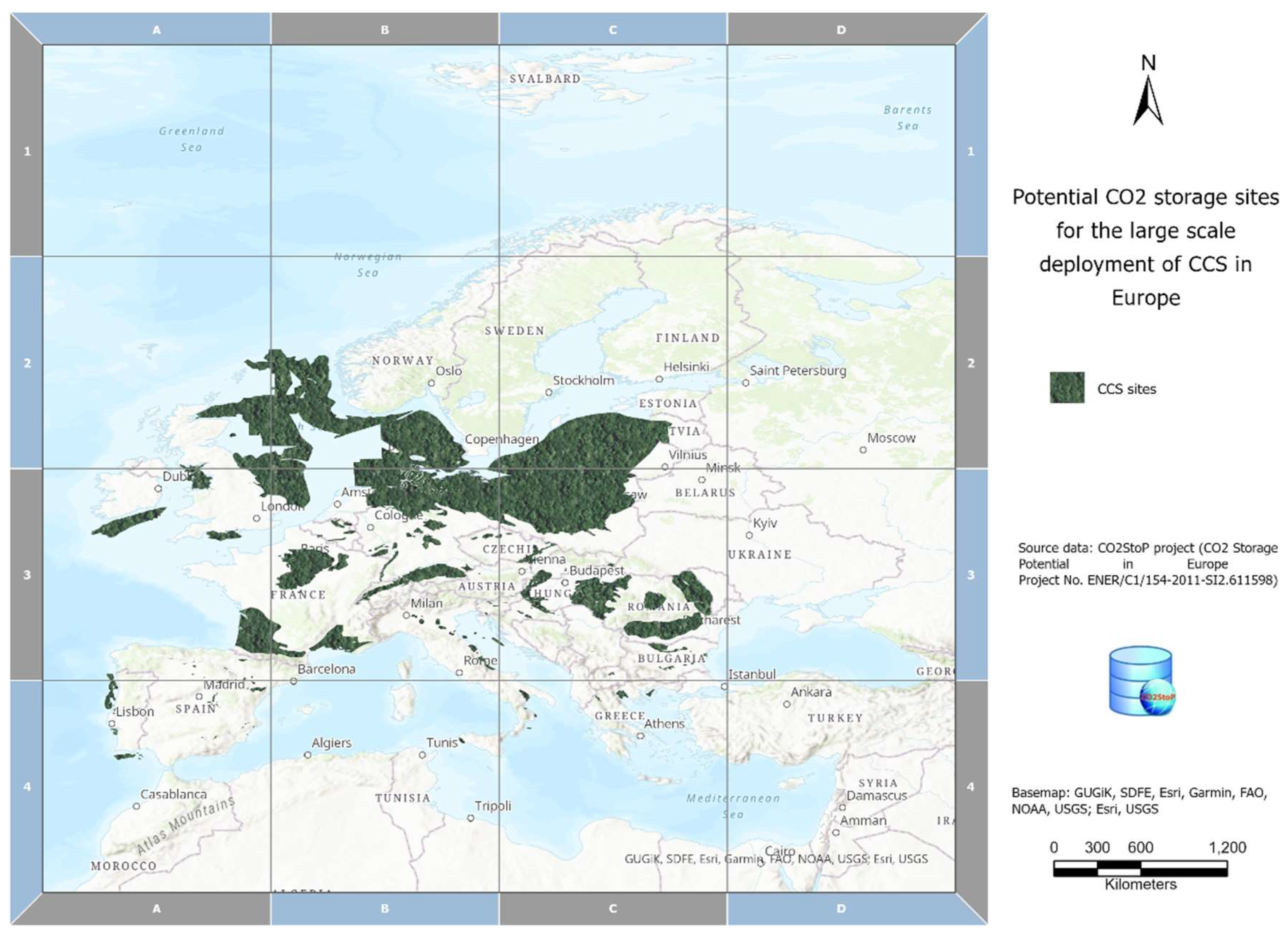
3. Strategies and Mechanisms of CO2 Storage in Europe

Contingent upon reservoir conditions, CO2 can be sufficiently stored in the form of compressed gas, liquid, or at supercritical state. The most common trapping mechanisms of CO2 storage are (1) stratigraphic/structural or hydrodynamic, (2) residual storage, (3) geologic solubility storage, and (4) mineral sequestration [41]. Once CO2 is injected, the subsurface will spread laterally while synchronously rising until it meets, by chance, a caprock that possesses a capillary entry pressure higher than the buoyancy or hydrodynamic force (buoyancy effect). This trapping, namely, structural or stratigraphic trapping, or what is often called hydrodynamic trapping, is favored because of the low permeability of the caprock. This mechanism is the most valuable because it is necessary for most storage sites, as this prevents CO2 leakage [42]. Structural and/or stratigraphic trapping is determined by the rock’s characteristics, the pore volume, and reservoir permeability.
Residual trapping happens when the injected CO2 expels formation fluid as it flows through the rock formation. As a result of the capillary force, the remaining CO2 is trapped by the expelled fluid within the pores of the rocks, so that it becomes immobile [43].
In solubility trapping, CO2 dissolves into the formation fluid. The density of the brine will slightly increase by the dissolution of the CO2. That slight density difference is enough to benefit the transmission flow, which is likewise a mechanism of CO2 trapping [44]. CO2 solubility within groundwater is influenced by temperature and salinity. When the temperature and salinity rise, then solubility decreases.
Mineral trapping is related to the formation of new stable mineral phases via geochemical reactions in the reservoir [45]. As time passes, the injected CO2 will dissolve into the brine and set up an important number of geochemical reactions, many of which could promote mineral trapping. This mechanism depends on the structure, mineralogy, and hydrology of the surrounding formations, while the reaction rate of mineral forming depends on the temperature, pressure, pH, and the contact lithotypes with the CO2 bearing brine. Natural mineral trapping is a very slow process and, without human intervention, would only be able to occur through many thousands of years.
Geological storage comprises injecting CO2 within rock formations that can safely absorb and store it for many thousands of years. Formations that have been considered as suitable for storing CO2 are found in sedimentary basins, were sediments have accumulated and gone through diagenetic processes through the geological periods. Sedimentary basins usually have an extent of thousands of kilometers [46]. According to the CO2StoP project (CO2 Storage Potential in Europe), which began in January of the year 2012 and concluded in October of 2014, by including information from 27 countries (Figure 3), a database was created as part of the project that contains the information required to evaluate potential CO2 storage locations. A data analysis system was formed to analyze the database’s complex data, as well as a Geographical Information System (GIS) capable of displaying the locations of suitable geological storage formation sites, the individual assessment units, and other subdivisions (daughter units that include hydrocarbon reservoirs or structural saline aquifer traps).
Un-mineable coal seams have been proposed as suitable for CO2 storage purposes. Lately, the possibility of storing CO2 in basalt formations is being considered. Aquifers and oil reservoirs involve storing CO2 within the pore volumes of subsurface rocks. The injected CO2 is restrained on the coal matrix as a result of adsorption into the coal seams. Carbon mineralization (i.e., a chemical reaction) is the storage mechanism in basalt. Geological storage is not possible to accomplish globally as Earth’s geology differs. Summarizing, four options appear to predominate for storing CO2 in geological formations, including saline aquifers, depleted oil reservoirs, coal seams, and silica-undersaturated basaltic rock formations. Nowadays, around the Europe Union, there are Commercial- and Pilot/Demonstration-scale CCS Facilities. These CCS Facilities, both active and those in the implantation stage, are assembled in Table 1, Figure 4.

3.1. CO2 Storage in Saline Aquifers

Saline aquifers include geological formations consisting of water-permeable rock formations that are saturated with brine. The amount of CO2 that can be stored in saline aquifers is large. Saline formation trapping mechanisms include solubility trapping, mineral trapping, structural trapping, and residual trapping. There are vital properties an aquifer must meet to be considered suitable for CO2 storage. These properties are the following: sufficient porosity, permeability, thickness, adequate depth, and an impermeable caprock [47]. Potential storage sites must be geologically stable regarding their tectonic activity, which may form pathways for CO2 to migrate from the reservoir through the caprock and even to the surface. In contrast to other types of storage sites, saline aquifers often hold vast trading and large territorial coverage. Accordingly, it is more likely to be placed close to CO2 emission sources, and therefore, the cost of transporting the CO2 decreases [48,49]. The most urgent challenge regarding CO2 sequestration within saline aquifers is potential pressure gathering and CO2 mobilization in the formation, which could possibly cause the fracture of the formation, reactivate any faults, and finally lead to CO2 leakage [50].
In the European Union, there are chiefly two commercial-scale CCS deployed projects in saline aquifers, which are the Sleipner project (country) and the Snøhvit project (country). Besides the aforementioned large-scale CCS projects, there is also a small-scale project, the Ketzin pilot site in Germany.
Considering the Sleipner Project, the injected CO2 came from its separation from methane formed at the Sleipner land at the North Sea. The injection took place at the Utsira Sand aquifer formation; from 1996 when it was initiated until 2018, an amount of 18 million tons were injected [51]. With regard to the Snøhvit project, the operation started in 2008. With knowledge from the Sleipner project, in the Snøhvit CCS project, CO2 was separated from the liquefied natural gas (LNG) project and injected within the deeper Tubåen Formation, which is in the Barents Sea. By 2012, an amount of 1600 ktons of CO2 had been injected, and it is estimated that ~23 million tons of CO2 can be safely stored based upon the project’s estimated lifetime period [52,53]. The Ketzin pilot site has been developed since 2004; by 2012, an amount of 61,400 tons of CO2 were safely stored into 630 m to 650 m deep sandstone formations (U. Triassic Stuttgart) at an anticlinal structure of the Northeast German Basin [54]. This enhances public acceptance of such pilot projects to be developed under such detailed modeling and monitoring operations.

3.2. CO2 Storage within Depleted Oil and Gas Reservoirs

Oil and natural gas reservoirs are considered optimum geologic storage sites since they have stored hydrocarbons for even millions of years, displaying properties appropriate for CO2 storage. Once oil and natural gas have been removed from an underground formation, it leaves permeable and porous volume pores that could be filled with CO2. Injecting CO2 could further enhance oil production through mobilizing fluids towards producing wells by a process called enhanced oil recovery (EOR). Moreover, oil and gas reservoirs have an abundance of existing equipment established on the surface and underground that can be reused for CO2 storage with small-scale conversions. There are many large, abandoned, and mature oil-gas offshore fields in Europe (despite their cumulative CO2 storage capacity falling below what is possible within saline aquifers). Fine examples are the onshore and offshore gas fields in N. Germany and in the Netherlands, as well as in the south parts of the North Sea. The CO2 amount that could be stored within depleted gas fields depends highly on the quantity of gas that was produced and also on the depletion grade of the field.

3.3. CO2 Storage in Coal Beds

Un-mineable coal is coal that, because of geological, technological, and economic factors, cannot be mined but could be a potential storage site for CO2. To be considered for CO2 storage, the ideal coal seam should display proper permeability and also be regarded as un-mineable. Coal seams could also store methane (CH4), which could be developed in conjunction with CO2 injection; this process is known as “enhanced coal bed methane (ECBM) recovery”. As previously mentioned, the injected CO2 is restrained on the coal matrix as a result of adsorption into the coal seams, whereas CH4 is also released and produced. This entrapment mechanism is considered everlasting. Coal beds are beneficial because of their position, which is usually nearby to an existing or planned coal-fired power plant. As a result, transportation costs may be reduced.

3.4. CO2 Storage in Deep Ocean

The CO2 could be directly injected within the deep ocean at water depths exceeding 2700 m [55,56], where liquid CO2 could sink into the seafloor; this occurs because the CO2 is denser than seawater under relatively high pressure and at low temperature conditions [56,57]. The storage capacity is very high because of the enormous volume of the ocean. On the other hand, this CCS mechanism is not easily applied since it can influence the marine environment.

3.5. CO2 Storage in Deep-Sea Sediments

The choice of injecting CO2 into deep-sea sediments combines the advantages of geologic storage as well as ocean storage, preventing many shortcomings [58,59,60,61]. To explain in more detail, there are no potential harms posed to oceanic ecosystems, and this happens because the CO2 targets deep sediments rather than the oceanic water. The storage mechanisms are similar to terrestrial sequestration mechanisms, such as dissolution trapping, residual trapping, as well as mineral trapping, which still constitute a critical factor. It should also be noted that innovative storage mechanisms, such as gravitational and hydrate trapping, are also applicable in the sequestration. Gravitational trapping is enhanced by the higher density that leads CO2 in the sea [57] to the widely mentioned negative buoyancy zone (NBZ). The optimum depth for the salinity and temperature-dependent density of seawater is exactly 2700 m [62]. Hydrate trapping acts due to CO2 hydrate development at high pressure and low temperature conditions [59]. We would like to point out that, in the first injection stage, a small number of hydrates develop at the lower parts of the hydrate formation zone (HFZ), promoting limitation of the caprock’s permeability. The area of the hydrate caprock increases with larger amounts of CO2 and, as a result, reaches the bottom of the HFZ and limits the CO2 underneath it. At the same time, CO2-saturated fluids are expected to sink downwards as a result of buoyancy-driven advection. At the end, the hydrated CO2 and also the CO2 liquid are expected to dissolve in seawater and turn into CO2 aqueous solution via diffusion and permanent storage mechanisms. Despite the large capacity and feasibility of this technology, it remains at the readiness level of formulation technology. Furthermore, CO2 storage in deep-sea sediments is much more costly than onshore methods. Additionally, it requires a great deal of time to increase the method’s acceptance by society [60,63].

CO2 Storage in Basalt Rock Formation in Europe

The physicochemical properties of basaltoid rocks, but also of other rock formations within basaltic layers, are considered proper candidates for CO2 storage. The mineralogy of basalts can allow injected CO2 to interact with Ca and Mg to develop stable and safe carbonate calcite and dolomite. This process represents a valuable tool for CCS since mineralization permanently stores carbon in a solid mineral structure, which allows CO2 to be captured within its structure. Carbon mineralization can be implemented through the following methods: (1) in situ, in which CO2-enriched fluids move through the rock pores; (2) ex situ, in which an alkalinity source is moved to a CO2 capture site at relatively high temperature and pressure conditions in a vessel reactor; (3) surficial mechanisms by which CO2 reacts with the alkalinity source above the surface [64]. Carbon mineralization costs depend on available CO2 and the alkalinity conditions of the reaction [64].
Basalts are Ca, Mg, and Fe-rich volcanic rocks that can be used for CO2 storage via mineralization purposes. CO2 mineralization in basaltic rocks is achieved through the reaction between Ca-Mg-Fe-rich minerals and carbonic acid. The latter comes from injected CO2 dissolution and the subsequent increase in water reactivity due to H+ release. Some of the most common carbonate minerals that can be formed include calcite, magnesite, dolomite, and siderite, as it is described by the following mineralogical reaction [34,65]:
(Ca,Mg,Fe)2+ + H2CO3 → (Ca,Mg,Fe)CO3 + 2H+
Selection of the appropriate basaltic types for CO2 mineralization depends on a series of physicochemical criteria that include: (a) an abundance of Ca, Mg, and Fe-rich minerals, (b) a low silica saturation of the basalt, (c) a high porosity–permeability, and (d) the alteration degree [65]. In addition, the total volume of the basaltic outcrops, as well as their proximity to water sources, are two important factors that should be considered before application of in situ CO2 mineralization. Thus, despite the wide distribution of basaltic rocks on Earth [34,66,67], only a few types can be considered for CO2 storage based on the above-mentioned criteria.
Mineralogical reactions
Basalts are predominantly composed of glass and, to a lesser extent, magmatic minerals such as olivine, clinopyroxene, orthopyroxene, spinel, and plagioclase. Hence, the efficiency of CO2 mineralization in basalts is closely linked with the carbonation rate of the distinct magmatic components (minerals and glass). Carbonation of olivine (reaction-2) is a natural process that develops slowly, which should be enhanced in large-scale storage projects [23,68,69]:
Ol + 2CO2 → 2Mgs + SiO2(s)
Results from experiments suggest that olivine dissolves at higher degrees under more acidic conditions, from 10−11 to 10−8.5 mol/m2/s for a pH range of 13 to 1.5 [34,70]. Regarding the temperature conditions, Kelemen et al. [71] suggest that olivine exhibits an optimal carbonation rate at ~185 °C.
Dissolution of clinopyroxene is controlled by the mineral (3). Experimental results suggest that, after the injection of the water-dissolved CO2, the subsequent pH decrease will lead to increasing dissolution rates of clinopyroxene-rich basalts [70]. In particular, the dissolution rate of augite ranges from 10−12 to 10−8 for mol/m2/s for a pH range between 7.3 and 2 [70]. Experimental results of the carbonation rate of diopside also indicate that alkaline conditions (increasing pH values) reduce the diopside dissolution [72].
Cpx + 4H+ → Mg2+ + Ca2+ + 2H2O + 2SiO2(aq)
Another important parameter that must be considered for the dissolution rates of diopside and glass in basalts is the carbonation coating phenomenon [73]. Experimental results reveal that carbonate coatings can decrease the dissolution rates of SiO2, CaO, and MgO in diopside and in the glass of basalts, when the liquid solution is saturated in calcite at pH: 8 and 70 °C [73], consequently affecting the cation release from the dissolved basalt to the liquid phase.
Orthopyroxene appears as an accessory mineral phase in basaltic rocks. However, its dissolution can contribute additional amounts of Mg2+ according to the mineral reaction-4:
Opx + 2H+ → Mg2+ + SiO2 + H2O
The formation of calcite during the mineral carbonation of basalts is linked with the available Ca2+ cations in the solution, which are mostly derived after dissolution of calc-silicate minerals including anorthite and clinopyroxene, as well as from the dissolution of the glass-rich groundmass. The reaction for dissolution of anorthite and precipitation of calcite [34] are given below:
An + 8H+ → Ca2+ + 2Al3+ + 4H2O + 2SiO2(aq)
Ca2+ + CO2 → CaCO3 + 2H+
The glass matrix is an important factor that substantially affects the carbonation rate of basalts during the injection of CO2. Experimental results have shown that, for a pH range of ~12 to ~6, the glass-enriched basalts are dissolved at considerably lower rates compared to clinopyroxene- and forsterite-rich basalts [74,75]. However, further pH decreases from ~7 to ~3 will lead to rapidly increasing dissolution rates of the basaltic glass [74,75].
Mineralization storage in Basalt Rock Formation Projects in Europe
CarbFix (Iceland)
CCS has been included in the EU agenda since 2007, whereas the first EU directive on CCS was published in 2009 [76]. At the current stage, only two large-scale field projects of in situ CO2 mineralization in basalts have been deployed, whereas some of the recent projects were cancelled mostly due to financial and/or regulation issues (e.g., Jänschenwalde project in Germany and Porto Tolle project in Italy [76]). The CarbFix project in Iceland (Hellisheiði Geothermal Power Plant) aimed to create a technology for the removal of CO2 from the atmosphere and its subsequent storage into basalts [77]. CarbFix was aligned with Directive 2009/31/EC for the geological storage of CO2 in basalts [77]. It was a pioneering and comprehensive scientific project, whose results give important insights and unravel key parameters for the successful implementation of CO2 storage in basalts worldwide. Estimations of the CO2 sequestration into the basalts of the CarbFix site indicate a 0.33 Gt storage capacity, whereas the estimated CO2 storage potential in the active rift zone of Iceland is 6100 Gt [78]. The CarbFix program in Iceland has now progressed from a pilot (original CarbFix) [79] to the industrial scale (CarbFix2) [80]. The project conducted detailed geological and hydrological characterization of the region, including hydrochemical modeling [77]. The following regulations were applied during the initiation of CarbFix [65]: (a) planning actions, (b) environmental impact assessment (EIA) studies including groundwater contamination, (c) health regulations, (d) safety regulations, and (e) regulations associated with greenhouse effects and radiation.
Considering the technical parameters of the project, the concept was based on two major pillars. The first was the injection of water-dissolved CO2 into basalts because of its higher density compared to common fresh water, which renders it more difficult to return to the surface [77]. The second characteristic is related to the acidic nature of the CO2-charged water, which makes it appropriate for the development of dissolution reactions that release high amounts of cations such as Ca2+ and Mg2+. The CO2 injection was based on the Manhattan Project [81], in which CO2 was injected into a pipe reaching 350 m depth, and it was released into groundwater in the form of bubbles. It should be mentioned that the CO2 that was dissolved with water is afterwards injected within the basaltic-bearing aquifers in proximity to the Hellisheidi geothermal power plant. Another critical issue that was considered was the injection depth, which is highly linked with high injection pressures [77]. Thus, CO2 was injected into local groundwater in order to achieve better dissolution of the CO2 and, consequently, better performance for mineral reactions. The monitoring of the dissolved CO2 was based on variable tracers [77,82,83]. However, significant concerns were raised during the implementation of CarbFix, which were recorded and assessed for the improvement of the method. In summary, the major issues were the following [77]: (a) problems associated with the separation of CO2 and H2S; (b) pore-clogging issues of the sparger, which were solved by re-designing and constructing the sparger; (c) problems associated with the low permeability of the injection wells due to discontinuous gas injections that caused pH changes; (d) pore-clogging of the subsurface aquifer due to the presence of Fe-oxidizing bacteria [77,84,85]; and (e) explosion issues. The evolution of CarbFix is the EU-funded CarbFix2 project, which aims to store CO2 into submarine basalts based on the advantage of inexhaustible seawater supplies [77,86]. The injection is developed in the Húsmúli re-injection region, and the project seeks to provide cost-effective and technically mature capture and storage of CO2 and H2S [87]. Following the major principles of CarbFix, the captured and dissolved CO2 and H2S react with basalts, allowing the release of cations such as Ca2+ and causing subsequent pH decrease, leading afterwards to the precipitation of carbonate and sulfide minerals [88].
Basalt that includes about 10 wt% CaO [89], as well as MgO and FeO in sufficient amounts, is highly reactive. Through this, carbonates precipitate at great depths due to carbon sourced from CO2 injection, as well as from Ca, Mg, and Fe sourced out of basalt alteration. At a pilot scale, carbonate precipitated in two years’ time with injection temperatures of 20–50 °C and only a few months between 60 and 260 °C [79,80,90]. This technique poses the advantage of carbon stored in the form of carbonate minerals, a highly robust substrate compared to supercritical CO2 being stored via other CCS techniques, and this technique allows stable storage for a prolonged period of time [79,91].
The CarbFix project focuses on CO2 crystallization within alkali basalts for permanent storage. CO2 injection within basalts provides many advantages over other methods since it can achieve fast mineralization with its large potential storage volume [67,91,92,93]. Through this method, CO2 is dissolved within water before injection into highly porous basalts [35,79,91]. Basalts are enriched with CaO, MgO, and FeO. After being dissolved, CO2 is no longer buoyant, and the acidic CO2-charged fluid promotes the release of these elements via basalt dissolution, allowing calcite, magnesite, siderite, and carbonate solid-solution formation [34,91], thus achieving CO2 storage.
The CarbFix project has been mentioned in many papers [89,90,94]. It is deployed in SW-Iceland, ~30 km eastwards of Reykjavik and ~3 km SW of the Hellisheidi geothermal power plant. This power plant annually produces ~40,000 tonnes CO2 and 12,000 tonnes of H2S as byproducts of geothermal energy production; the gases are of magmatic origin.
The Case of Orca (Iceland)
Carbfix was initiated with the injection of CO2 that was previously captured by the plant of Climeworks’ Orca (Iceland), which is the first commercial chain of direct-air capture and storage worldwide [8]. The Orca chain will combine underground CO2 storage in the form of minerals with direct-air capture at a rate of 4000 tons of CO2 per year [20]. Climeworks increases the CO2 capture per module, leading to the maximum capture and storage capabilities worldwide [27].
The Case of Grundartangi Plant (Iceland)
The Norwegian Aker Carbon Capture is collaborating with Carbfix and Elkem Iceland to reduce the produced CO2 emissions by the ferrosilicon plant of Elkem in Iceland via the implementation of CCS technologies within basalts [30].
The Case of Carbfix Coda Terminal (Iceland)
Potential geological storage “reservoirs” for mineralized CO2 also comprise sedimentary rock formations, such as sandstones. Sandstones have been suggested mainly because of their high permeability, their great geographical distribution, and their physicochemical features [95,96,97,98,99]. Sandstones possess the appropriate properties for energy storage due to their compositional (e.g., CaO- and SiO2-rich), textural, and structural features, as well as their low alteration degrees [19,100,101].
Mafic- and basalt-derived sandstones in Europe are relatively frequent occurrences. The intra-basaltic sandstones in the Faroe-Shetland Basin in the UK are a good example of such rock types [4,102,103]. Despite the fact that the mineralogical composition of basalt-derived sandstones is characterized by high Ca2+, Mg2+, and Fe2+ contents (rendering them appropriate for carbon sequestration), there are several issues that should be resolved regarding their suitability for CO2 storage, such as their storage capacity and their distance from CO2 sources [4].
Calcite- or dolomite-rich sandstones, in which carbonate minerals are cement materials (reaching up to ~11% of the rock mass), have different physicochemical and mechanical properties compared to the low-carbonate cement types; hence, the dissolution of the carbonate cement close to the injection site can lead to the formation of more acidic water solutions, rendering them more reactive in terms of mineral dissolution and leading to subsequent increases in permeability and porosity [4]. In addition, the combination of the ions results in re-precipitation phenomena and the formation of second-generation carbonates [4,104,105].
Greywackes include sand grains within fine-grained clayey matrix, in which the clay fraction is higher than 15%. The sand-sized grains usually contain rock fragments with diverse mineralogical composition (e.g., pyroxene, amphibole, quartz, and feldspars), whereas clayey parts are usually rich in chlorite and biotite [4]. Despite the suitability of their mineralogical composition for CO2 storage, the clay-rich matrix of greywackes lowers their porosity and permeability, leading to decreased injectivities [4,105].
Redbeds and glauconitic sandstones are Fe-rich sandstones that contain high hematite quantities and iron-rich micas, respectively, which can supply Fe2+ during the addition of SO2 or H2S in the injection stream [4]. Thus, hematite can lead to the formation of siderite (FeCO3) or ankerite (CaCO3, MgCO3, and FeCO3) during Fe reduction [4].
Arkosic sandstones include feldspars, and they can also be deployed for CO2 storage purposes due to their relatively high quantities of anorthite, whose carbonation is described by the following reaction [4]:
CaAlSi2O8 + H2CO3 + H2O → CaCO3 + Al2Si2O5(OH)4
The mineralogical composition of arkosic sandstones, such as those of the Klepa Nafpaktias (Greece) [97], promotes their CO2 storage capacity since K-feldspar can react with the injected supercritical CO2 according to the following reactions (8) and (9):
2KAlSi3O8 (K-feldspar) + CO2 + 2H2O → Al2(Si2O5)(OH)4 (kaolinite) + 4SiO2 + K2CO3
3KAlSi3O8 (K-feldspar) + H2O + CO2 → KAl3Si3O10(OH)2 (illite) + 6SiO2 + K2CO3
Thus, the dissolution of alkali feldspars is expected to enhance clay mineral formation and quartz crystallization. This case presents many similarities with that described for the Mesohellenic Trough (NW Greece), which investigated the potential of CO2 storage within porous sandstones that are overlaid be a less permeable caprock formation [23,96,99,106].
Based on Hangx and Spiers [107], plagioclase of basic chemistry is expected to develop both types of secondary minerals, although clay precipitation may likely precede that of carbonate. Moreover, the presence of albitic plagioclase is expected to lead to kaolinite and dawsonite crystallization, depending on the rock/water/CO2 proportions through these reactions [95,108]:
2NaAlSi3O8 (albite) + 2CO2 + 3H2O → Al2(Si2O5)(OH)4 (kaolinite)+4SiO2+2Na++2HCO−3
NaAlSi3O8 (albite) + CO2 + H2O → NaAlCO3(OH)2 (dawsonite) + 3SiO2(chalcedony)
According to Christopoulou et al. [99], the mineralogical compositions of sandstones are highly associated with successfully achieved CO2 sequestration. They suggested that specific mineral phases are considered critical in relation to the capacity of a rock to sequestrate CO2. The minerals that likely develop a positive effect on sequestration are serpentine, epidote, K-feldspar, plagioclase, and mica-group minerals. On the contrary, quartz, the matrix (given the fact that it is not composed of clay minerals), dolomite, and calcite are reported as inhibitory components. Based on the above petrographic and mineralogical indications, they proposed the following index:
PrP = (Serp + Ep + Kfs + Pl + Mica)/(Qtz + Cment + Cc + Dol),
The petrographic results of the PrP index (Potential reactive Phases) demonstrate a clear correlation per sandstones and, therefore, per lithological formation. When the index tends to the unit of “1”, the rock becomes more suitable to retain CO2 within its structure.

4. Carbon Capture and Utilization Pathways in Europe

Several technologies related to the utilization of CO2 are available, some of which include the use of CO2 in chemicals, fuels, and durable materials and the use of CO2 in mineral carbonation and construction materials, along with the use of CO2 in biological algae cultivation and enzymatic conversion, especially attracting technologies at higher levels of maturity. Among others, CO2 can be naturally converted into materials through photosynthesis, ultimately producing biomass, but it is also being used in applications such as the extraction of compounds with supercritical CO2, dry cleaning, and uses in the food industry. Europe, through projects and industrial initiatives, is making a strong contribution to science, research, and innovation in the CCU field.

4.1. CO2 in Chemicals, Fuels, and Durable Materials

CO2 can be converted into various useful chemical products and synthesized fuels that can replace current chemical feedstock in the chemical, pharmaceutical, and polymer industries. The most important applications are urea (~160 Mtyear−1), inorganic carbonates (~60 Mtyear−1), polyurethane (~18 Mtyear−1), acrylic acid and acrylates (10 Mtyear−1), polycarbonates (4 Mtyear−1), and alkylene carbonates (a few ktyear−1). Many applications that concern pharmaceuticals, agrochemicals, polymers, lubricants, coating, and catalytic reactions are another category of chemicals that can be produced from captured CO2.
Formic acid is another important chemical that could be formed through CO2 utilization. Hydrogenation of CO2 into formic acid has been gaining interest mainly due to the mild reaction conditions, the lack of formation of byproducts, the ability to store hydrogen in liquid form, and the easy decomposition of formic acid into hydrogen and CO2. CO2 hydrogenation is a promising method, as the inherent chemical energy of hydrogen carriers is used to support the CO2 conversion, even though the source of hydrogen is critical since 96% is produced out of fossil fuels, leading to higher CO2 emissions.
It should be noted that the use of CO2 in energy storage is accomplished taking into consideration power-to-fuel technology (including power-to-gas and power-to-liquid), using renewable hydrogen [109]. Methanol constitutes one of the most effective commercial-scale ways to transform CO2 nowadays. This constitutes a tool for producing several industrial chemicals that comprise formaldehyde, acetic acid, methyl tertiary-butyl ether (MTBE), and dimethyl ether (DME) [110]. Dimethyl carbonate (DMC) can also be formed from CO2 and methanol. This can be used as a solvent in transportation fuel [111]. Methane production, through the Sabatier reaction, is a crucial catalytic conversion process [112]. The methane produced in the reaction is commonly referred to as synthetic natural gas (SNG). It also enables the storage of large amounts of renewable energy in existing natural gas grid storage systems and can be directly used in most endothermic engines and other known natural gas facilities [113].
In addition to CO2 hydrogenation, another process that has attracted interest is the electrochemical transformation of CO2 [114,115,116]. The materials of electrodes and catalysts, the pressure and concentration of CO2, reaction medium, temperature, pH, buffer strength, and electrolyte solution play crucial roles in the electrochemical transformation’s products, such as formic acid and/or formate, carbon monoxide, ethylene, and ethanol. Dry re-forming of methane that acts as the intermediate product, which could be converted into added-value fuels or chemicals, through the confirmed Fischer–Tropsch process are responsible for Syngas production [117]. CO2 may react with various organic compounds (alcohols and amines) for producing useful chemicals in the pharmaceutical and agrochemical fields (open and cyclic carbonates and carbamates) [111]. Furthermore, some available pathways can also utilize CO2 as a feedstock for producing carbon-based materials, such as polymers, [118] carbon fibers, and composites, as well as fine chemicals [111,119].

4.2. CO2 for Mineral Carbonation and for Construction Materials

Mineral carbonation of CO2 constitutes a new tool for CO2 storage. There are various ways to accomplish carbon mineralization, regarding mineral ore use [64]. In situ mineral carbonation leads to CO2 injection into rocks. It circulates through subsurface porosity and reacts with different minerals, mainly calcium or magnesium silicates, which form solid precipitates [37,120]. Such alteration is thermodynamically favored despite the slow kinetics. At the surface, the concentrated CO2 is reacted with the alkalinity source on-site. On the other hand, in ex situ mineral carbonation, the process is chemically performed at industrial scale. The alkalinity source is further transported for CO2 capture; combined with CO2 at high temperatures and pressures, this leads to stable mineral carbonates, such as sodium carbonate and bicarbonate, calcium, and magnesium carbonate [29].
In order to capture one ton of CO2, an amount of three to four tons of mineral ore is needed [121]. For CO2 mineralization, slow kinetics are presented as crucial. Waste byproducts, such as cement dust and steel slag, as well as air pollution control residues and biomass waste, are presented as important alkalinity resources [25]. Even though there are numerous studies regarding CO2 in mineral carbonation, and the potential of in situ mineralization is considered critical, the discussion in the following is constrained to ex situ mineralization since in situ mineralization is a component of the CCS strategy. This type of work has been performed by Azdarpour et al. [122]. Wang et al. [123] reviewed CO2 sequestration by mineral carbonation, combining mineral carbonation and the recovery of valuable metals from ore deposits and, at the same time, decreasing the total costs by cost shares for mineral recovery. CO2 also has another construction application (building materials). Two basic technologies for the injection of CO2 into concrete material have been observed: carbon curing and carbon conditioning. In the first one, unlike the weathering carbonation that is naturally observed in hardened concrete, CO2 gas may act as a curing agent, yielding a bonding matrix by improving the CO2-based material’s performance. Zhang et al. [124], when summarizing mechanisms, processing, and material performance associated with the carbonation curing of cement-based materials, highlights that it is conducive to a more sustainable stance for the concrete industry, while at the same time, it also allows the perpetual fixation of CO2 and a closing of the CO2 circle. Carbon conditioning is the injection of CO2 into recycled aggregate; the final product is referred to as CO2 concrete [125]. Tam et al. [126] made a comparison between CO2 injection within concrete and recycled aggregate concrete, concluding that carbonation of recycled aggregate is generally quicker and easier than that of concrete. On the other hand, the use of CO2 in cement-based materials was also examined by Jang et al. [127], showing that the capacity of maximum CO2 uptake by a cement-based material is approximately 0.5 ton CO2 per ton material, even though experimental CO2 uptake capacity ranges from 0.07 to 0.24 ton CO2 per ton material. It should be noted, at this point, that CO2 can be taken directly from flue gas emissions (with a CO2 concentration higher than 10%), [128] and CO2 mineralization could be succeeded by the aqueous accelerated carbonation reaction of calcium and magnesium silicates in alkaline solid wastes [129]. This direct flue gas carbonation has also been studied by He et al. [130], where the CO2 contained within the cement kiln flue gas was used to precast concrete plants for the manufacture of building products. In this process, expensive concentration or purification steps are unnecessary, while direct flue gas carbonation is likely profitable in the short term.

4.3. CO2 in Biological Algae Cultivation as Well as Enzymatic Conversion

Various algae can be used for converting CO2 into a variety of compounds, including different hydrocarbons, lipids, and other complex oils, resulting in alternative pathways in order to produce biodiesel and other biomass derivative products [131]. Velea et al. [132] selected thirty-five various microalgal strains and examined their growth rate and potential for CO2 bio-fixation using the emissions from a typical coal-fired power plant. Most algae species contain oil ranging between 20 and 50% (dry weight of biomass); the lipid and fatty acid ingredients vary based on culture conditions. Algae biomass can efficiently absorb about 1.83 tons CO2 per ton biomass [133]. Algae cultivation is conducted in an open or closed system. This could be carried out using various methods, including open raceway ponds and photobioreactors. In addition, there are a variety of factors that may play critical roles in algae growth, including light (quantity and quality), temperature, oxygen, salinity, nutrient availability, pH, CO2, and biotic elements such as bacteria [134]. Biofuel development generally involves the processes of settling, flocculation, filtration, flotation, centrifugal sedimentation, extraction, and purification. Zhang [135] studied current demonstration projects by using flue gas in order to grow algae. The status and applications of algae biofuels were also discussed by Adeniyi et al. [136]. Mustafa et al. [117] reviewed the enzymatic conversion of CO2 by oxidoreductases, lyases, and microbes. Cyanobacteria give great potential as they are naturally convertible, require simple nutrients, exhibit rapid cell growth, and can be used for biofuel generation [117]. Enzymatic and microbial electrolyzes also have good potential and are currently under development [137,138]. Yaashikaa et al. [115] also reported a list of bio-products obtained from CO2 and microbial species, including isobutanol, isopropanol, lipids, and methyl ketone. The optimal selection of microbes, physiological parameters, and design of the bioreactor can enhance biological and biochemical processes. The use of microbes has vastly increased to transform CO2 into high-value products. Many microbial species have been found to enhance the conversion process. In addition, various microorganisms can be genetically modified while at the same time increasing the yield and efficiency [117]. In order to recycle CO2 into organic products via microbial electrosynthesis, this may be considered an attractive option, especially in the context of circular bioeconomy and biofuel production. By following Bian et al. [139], the problems of lipid extraction in algae-based processes or unstable catalysts in CO2 electro reduction to generate CO2-based products with a relatively short carbon-chain are not encountered by microbial electrosynthesis, and this mainly happens because of the long-term stability of reactors as well as the high efficiency of CO2 reduction.

5. Social Aspect and Statistical Analysis
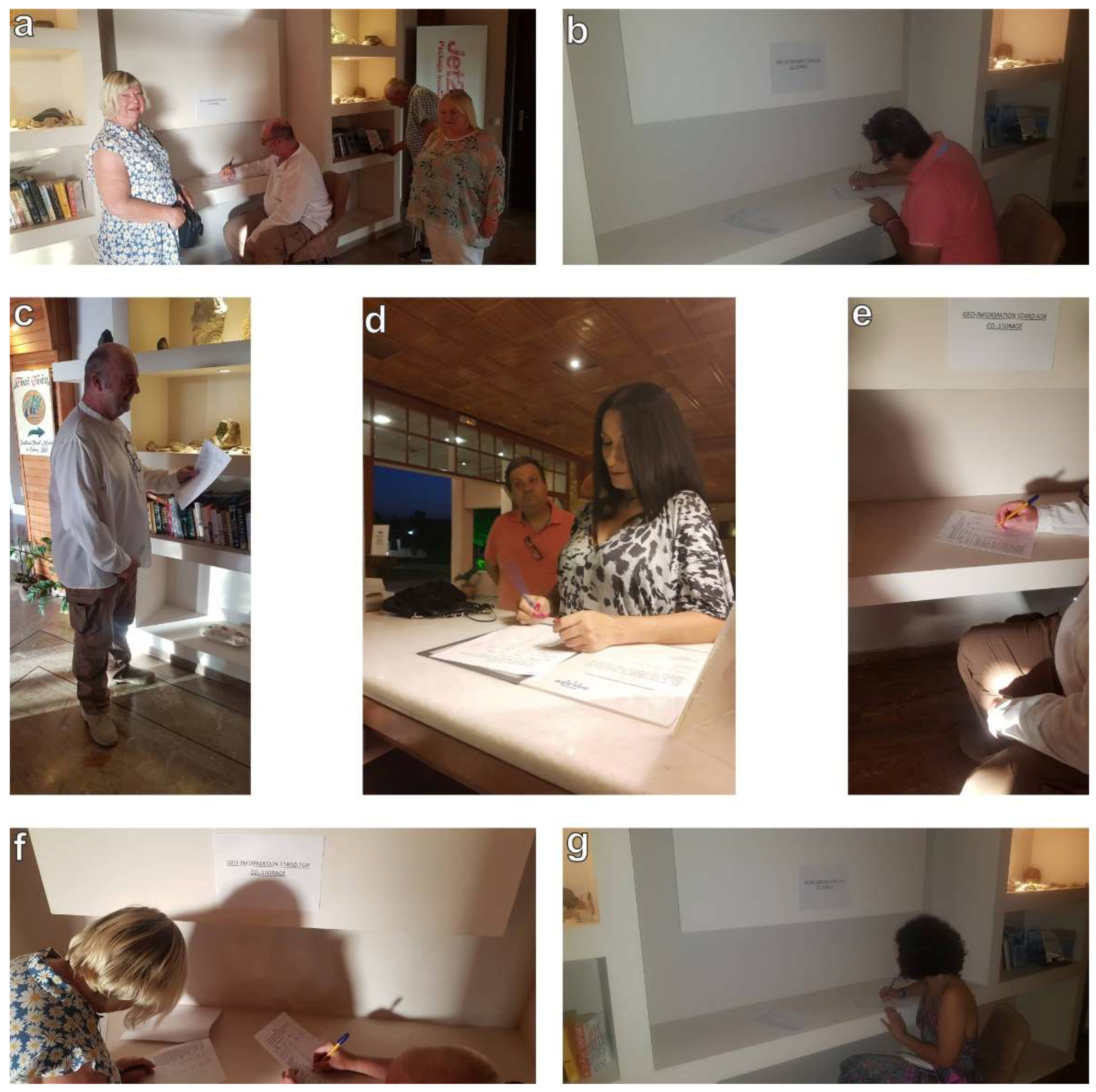
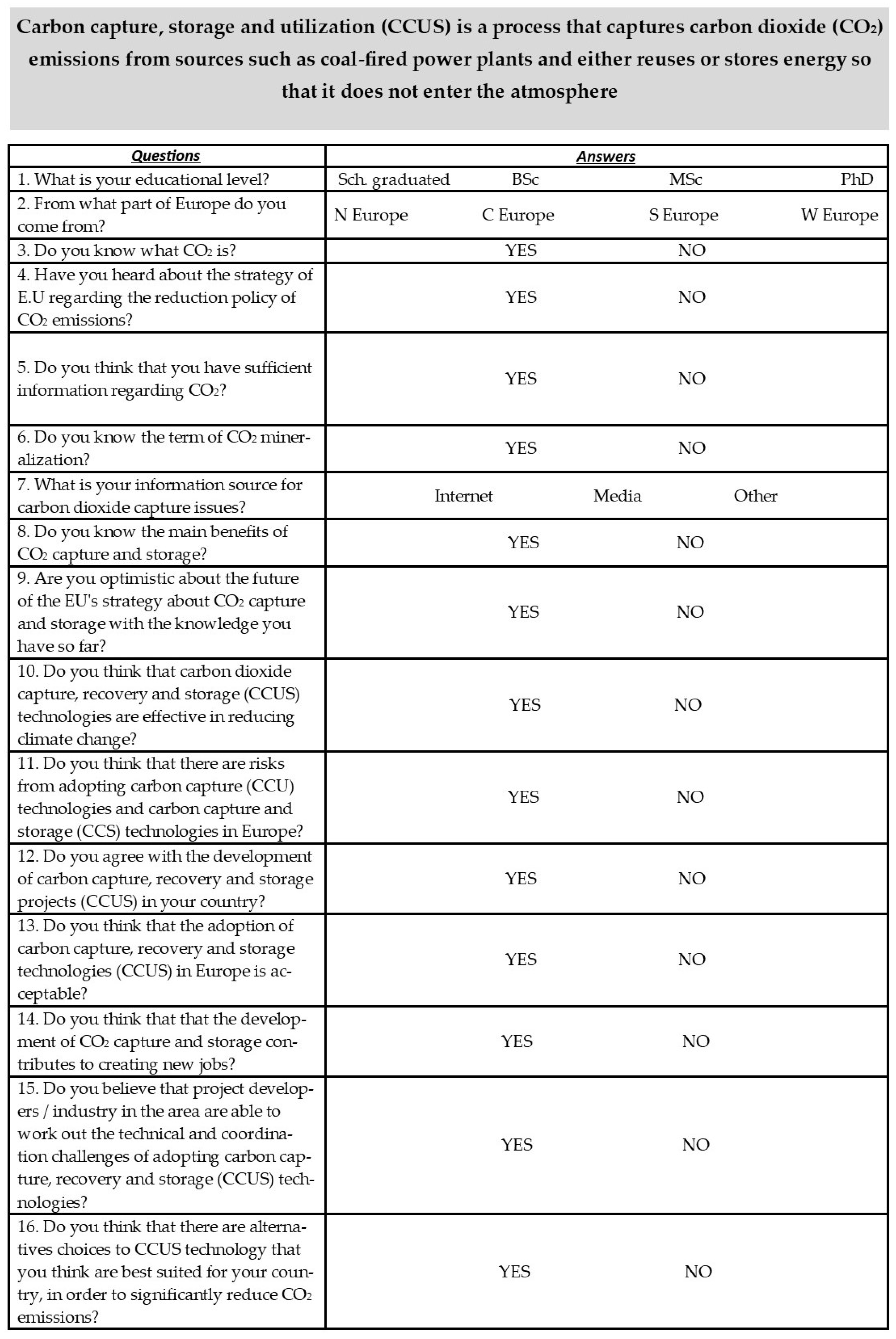
Social acceptance plays a crucial role in every conceivable implementation strategy. The introduction of CO2 storage technologies in countries such as France, Belgium, and Germany has resulted in great resistance to the concept itself among stakeholders and the public [140]. Despite the increasing research, as well as investment efforts, CCS deployment is usually followed by negative perceptions of CO2 transport and storage. Several projects regarding storage applications have been cancelled [141]. In contrast to CO2 storage, CO2 utilization seems to be more acceptable to most people. This may happen as CO2 is considered as waste recycling. Jones et al. [142] have studied public perception in the UK. They noticed limited awareness among many of the participants in the research, and they also noticed the need for further information about the issue. However, te interest has increased because of national and international legislation related to CO2 and other GHG emissions (e.g., EU ETS), leading to the innovation and development of CCU technologies as well. The important studies conducted on emerging perceptions of CO2 and product options (up to 2017) were summarized by Jones et al. [140]. Arning et al. [143] examined the social acceptance of CO2-derived foam mattresses, enhancing the lack of awareness of technical knowledge while at the same time having a positive perception of CCU. Moreover, these studies dealt with health and environmental issues regarding the use of CO2-based products (e.g., fear of allergies, soil concentration, and potential air pollution). Furthermore, Arning et al. [144] also mentioned the awareness of society concerning the sustainability and the end-of-life of CO2-based products. It was also concluded from the variety of the research that, as the sustainability of these products remains questionable, social acceptance remains limited.
The trust in stakeholders and researchers who deal with CO2 utilization constitutes a critical factor that generally influences research development. For this reason, local authorities play a significant role in informing society about CO2 storage and utilization, as well as about their opportunities [145]. In Barendrecht in the Netherlands, the local government rejected a project concerning CO2 utilization because they were aware of negative impacts on public health and environment [146]. Satisfactory efforts have been carried out [147] in some industries in order to limit the perceived risks while at the same time gaining wider acceptance of CO2 utilization methods/strategies from the community. To increase the level of trust of society in stakeholders and researchers, an information campaign regarding the opportunities of CO2 storage and utilization should be organized throughout Europe. It should be noted that there is a lack of studies concerning information on the current state of public perception and knowledge of CCS technologies. However, the results of certain studies [147] show that public awareness of CCS still remains low in various countries, such as Canada, the Netherlands, Norway, the UK, and the US. For public acceptance, the level of knowledge plays a crucial role [148]. Stakeholders interviewed by [149] in the ELEGANCY project rated public knowledge concerning CCS as rather low and believed that those CCS technologies are still not present in current public discussion due to low market penetration. The results of [150] in the context of an experiment indicate that CCS was observed more positively by those who claim to have more knowledge about CCS and that they were also likely to display a greater interest in the technology. It should also be mentioned that the evaluation of CO2 capture–storage–utilization options can change after an increase in information levels [151].

6. Questionnaire

As has already been mentioned in the methodology part, a questionnaire was given to 300 European citizens from various European countries regarding CO2 issues. The questionnaire is listed below in Figure 5, while the answers for it are presented in Figure 6 and Figure 7. As can be seen from the questionnaire, European citizens were called to answer how informed they are about CO2 issues, how optimistic they are regarding the solving of CO2 issues, as well as how much they agree to new methodologies being performed in their countries to solve CO2 environmental problems. As shown in Figure 6 and Figure 7, there was quite a low percentage of high educational level in the tested European citizens (23% had obtained an M.Sc. or Ph.D.), and the majority of them were from West and Central European countries (60%). Most of them were informed (mainly from media and internet) about CO2 and about the European strategy for solving CO2 problems, but they did not have knowledge regarding the used or proposed methods and technologies. Furthermore, they were not informed in-depth about the aforementioned technologies, not even about their advantages both for the environment and for society. They also seemed to be negative and hesitant about the adoption of these technologies in their countries.

7. Discussion and Suggestions for Future Research

In 2022, Europe is roughly halfway between the EU’s environmental policy innovation as it was established in 1980 and the EU’s 2040 vision of “prosperity within the planet”. At the heart of this vision is the recognition that Europe’s economic prosperity and well-being is inherently linked to its natural environment—from fertile soil to clean air and water. In the present study, studying the strategy of the last 40 years, the implementation of environmental and climate policies has provided significant benefits for the functioning of Europe’s ecosystems and also for the health and well-being standards of European citizens. In several regions of Europe, the local environment is reasonably good nowadays, as it has been since the beginning of industrialization, but this does not seem to happen in all of Europe. However, as shown in Figure 1 and Figure 3, although Europe presents high concentrations of CO2 in the atmosphere, it also has potential in the areas of high concentrations of CO2 where CO2 capture and storage can take place. This is a very encouraging event for the future of Europe and for the planet in general. Reducing pollution, nature’s protection, as well as better waste management have contributed to this. Environmental policies also create economic opportunities and therefore contribute to the Europe 2020 strategy, which aims to transform the EU into a smart, sustainable, and inclusive economy by 2030. Carbon-capture technology is considered as a source of hope for reducing global greenhouse gas emissions, mainly reflected in the climate plans of European countries, as well as in the respective strategies of some of the world’s largest oil and gas companies based in Europe. The issue, however, is still divisive, as researchers and environmental groups argue that carbon-capture technology is not a safe solution. However, as mentioned above, carbon capture and storage refer to a number of technologies designed to capture carbon dioxide from high-emission activities, such as power generation or industrial plants that use either fuels or biomass. European researchers who are working on the above capture and storage technologies believe that they can play a key role in achieving global energy and climate goals. The projects that appear to be currently underway in Europe as outlined above allow CO2 capture and storage or the production of clean energy from renewable sources, thus helping to achieve emission reduction targets by 2030, if implemented before that date. However, their main goal is to demonstrate the commercial potential of the selected technologies and to contribute more broadly and in the long run to a low-carbon economy after 2030, if they are applied in other parts of Europe and the world. The support of Europe’s pioneers in this field is expected to contribute to the realization of the EU’s ambition to become a leader in the development of renewable energy technologies worldwide.
The carbon sequestration and mineralization method can actually help to reduce carbon dioxide emissions and Europe’s sustainability and technological development. The effect of efficiency improvement on the emissions of CO2 from a coal-fired plant is shown in Figure 8. At 50% efficiency, a power plant will emit up to 40% less CO2 than the plant with a thermal efficiency of 30%. It should be noted here that the average global efficiency of coal-fired plants is currently 33% [152]. The addition of CCS will further reduce the emissions of CO2 by more than 85% in comparison with the reference plant without CCS. However, to achieve this reduction, the CO2 capture unit will consume up to 30% of the energy produced by the plant, which means more fuel must be burnt in order to generate the same amount of energy as the plant without CCS.
The greatest environmental risk associated with CCS relates to the long-term storage of the captured CO2. Leakage of CO2, either gradual or in a catastrophic leakage, could negate the initial environmental benefits of capturing and storing CO2 emissions and may also have harmful effects on human health. On the other hand, CCS has the long-term potential to make a substantial positive impact on the amount of CO2 emitted into the atmosphere by the stationary energy sector. Therefore, the potential risks need to be weighed against the potential benefits, as well as the possible consequences of inactivity.
Mineralization, according to the studies and research available now, promotes permanent and safe storage and could be the key to resolving the carbon dioxide crisis we face in our days. It is therefore proposed to launch new research and pilot projects across Europe so that we have more knowledge available and possibly more storage space.
At this point, it is proposed to create, in the long run, a database containing all the rocks of the European area, and mainly the basalts and sandstones that occupy a significant part of Europe. This database can be created through detailed petrographic mapping. In addition, tests should then be performed on an autoclaved carbon dioxide injection system to test the ability of the European rocks to be used for CO2 capture, storage, and further utilization.
Based on the questionnaire survey conducted in collaboration with a geo-friendly hotel in Kefalonia on a representative sample of 300 people in low-stress conditions for respondents and in a beautiful and natural environment, we identified important points that should be considered in any future research and/or pilot work that is carried out concerning the issue of CO2 capture and storage. The most important finding of the present study focuses on the fact that the majority of European citizens who participated in the survey, regardless of their educational level, have heard from some means of communication what CO2 is and what its effects are, and those who have a deeper knowledge have heard of capture methodologies; yet many consider them as unsafe methods. At this point, the greatest knowledge gap in the ordinary European citizen perhaps is observed. At this point, it seems that the European plan so far has failed, in part, as proper communication between European politics and society has not been achieved. In addition, perhaps a point that needs to be studied is the answers given to question 6, where the vast majority did not seem to have ever heard the term mineralization, which indicates that the scientific community, where it deals with the issue, should make efforts to make it well-known to a wider audience so that there is a holistic approach of science in society. The same conclusions are drawn from the answers to questions 8–11, where most of the citizens, on the one hand, do not know the benefits of such technology and, on the other hand, appeared to be pessimistic about the future of these technologies, which shows that European scientific and political strategy must still take several steps in the right direction. Exactly by following the same philosophy, the citizens answered the rest of the questions, regardless of their geographical destination. In order to ensure the desired social acceptance of the energy transition based on the experience gained in the design and implementation stages, it is proposed that all stakeholders improve the following elements: process independence, information quality and accessibility, freedom and participation diversity, clarity of arrangements, accountability and consideration of participation in decision making, transparency, and monitoring from the beginning to the completion of a project. The EU should make much greater effort to promote equal distribution and production–consumption through financial incentives, as this is the factor that has the greatest impact on the local acceptance of CO2 capture and storage, while the main goal should be to put citizens at the heart of politics and ensure that they can benefit from new technologies that need to be implemented at a much faster rate than they have been to date. In general, social acceptance by the community requires contact with citizens and stakeholders, as well as ensuring mutual trust through open communication and the opportunity to participate as early as possible in the development of actions and projects related to CO2 capture and storage, at all appropriate levels of government, from the local to the international.

8. Conclusions

The conclusions of this study seem to be double. The first one is related to the technologies used in Europe for CO2 capture and storage nowadays, while the second is related to the social acceptance of these technologies. Firstly, CO2 mineralization in various rock formations, such as basalts and sandstones, seems to be a useful, hopeful, and environmentally safe solution among other proposed solutions. The second conclusion focuses on the social acceptance by European citizens of such methods/technologies for solving CO2 issues in these days and, more specifically, the lack of information regarding the advantages of CO2 capture and storage technologies used in several countries in Europe. It should be mentioned that there should be an organized project in all countries in Europe in order to popularize and communicate the scientific knowledge to a wider European audience, with the ultimate goal being the consolidation of sustainable development in Europe.

Author Contributions

Conceptualization, N.K. and P.P.; methodology, M.C., P.P.G., A.R., E.G., C.K., K.P., P.K. (Pavlos Krassakis), D.P. and P.P.; software, M.C., P.P.G., A.R., E.G., C.K., K.P., P.K. (Pavlos Krassakis), D.P. and P.P.; formal analysis, M.C., A.R., D.P. and P.P.; investigation, M.C., P.P.G., A.R., E.G., C.K., K.P., P.K. (Pavlos Krassakis), D.P. and P.P.; resources, M.C., P.P.G., A.R., E.G., C.K., K.P., P.K. (Petros Koutsovitis), D.P. and P.P.; data curation, M.C., P.P.G., A.R., C.K., K.P., D.P. and P.P.; writing—original draft preparation, M.C., P.P.G., A.R., E.G., C.K., K.P., P.K. (Pavlos Krassakis), D.P. and P.P.; writing—review and editing, N.K., M.C., P.P.G., A.R., C.K., K.P., P.K. (Petros Koutsovitis) and P.P.; visualization, M.C., A.R., E.G., K.P., P.K. (Petros Koutsovitis), D.P. and P.P.; supervision, N.K. and P.P. All authors have read and agreed to the published version of the manuscript.

Funding

This research received no external funding.

Institutional Review Board Statement

Not applicable.

Informed Consent Statement

Not applicable.

Data Availability Statement

Not applicable.

Conflicts of Interest

The authors declare no conflict of interest.

References

  1. Tai, C.Y.; Chen, W.-R.; Shih, S.-M. Factors affecting wollastonite carbonation under CO2 supercritical conditions. AIChE J. 2006, 52, 292–299. [Google Scholar] [CrossRef]
  2. IPCC. Climate Change 2021: The Physical Science Basis; Contribution of Working Group I to the Sixth Assessment Report of the Intergovernmental Panel on Climate Change. In Proceedings of the 14th Session of Working Group I and 54th Session of the IPCC, Virtual, 26 July–6 August 2021; Cambridge University Press: Cambridge, UK, 2021. [Google Scholar]
  3. IPCC. Climate Change 2007: Synthesis Report. Contribution of Working Groups I, II and III to the Fourth Assessment Report of the Intergovernmental Panel on Climate Change; IPCC: Geneva, Switzerland, 2007. [Google Scholar]
  4. Hofmann, M.; Schellnhuber, H.J. Ocean acidification: A millennial challenge. Energy Environ. Sci. 2010, 3, 1883–1896. [Google Scholar] [CrossRef]
  5. BP. BP Statistical Review of World Energy; BP: Londok, UK, 2012. [Google Scholar]
  6. IEA. World Energy Outlook; OECD/IEA: Paris, France, 2010. [Google Scholar]
  7. Abu-Zahra, M.R.M.; Schneiders, L.H.J.; Niederer, J.P.M.; Feron, P.H.M.; Versteeg, G.F. CO2 capture from power plants. Part I. A parametric study of the technical performance based on monoethanolamine. Int. J. Greenh. Gas Control 2007, 1, 37–46. [Google Scholar] [CrossRef]
  8. IPCC. Carbon Dioxide Capture and Storage IPCC; IEA: Paris, France, 2005. [Google Scholar]
  9. Davison, J.; Freund, P.; Smith, A. Putting Carbon Back into the Ground; Climate Technology Centre and Network: Copenhagen, Denmark, 2001. [Google Scholar]
  10. Celia, M.A.; Bachu, S.; Nordbotten, J.M.; Bandilla, K.W. Status of CO2 storage in deep saline aquifers with emphasis on modeling approaches and practical simulations. Water Resour. Res. 2015, 51, 6846–6892. [Google Scholar] [CrossRef]
  11. Baran, P.; Zarębska, K.; Krzystolik, P.; Hadro, J.; Nunn, A. CO2-ECBM and CO2 Sequestration in Polish Coal Seam—Experimental Study. J. Sustain. Min. 2014, 13, 22–29. [Google Scholar] [CrossRef] [Green Version]
  12. Jalili, P.; Saydam, S.; Cinar, Y. CO2 Storage in Abandoned Coal Mines. In Proceedings of the 11th Underground Coal Operators’ Conference, University of Wollongong & the Australasian, Institute of Mining and Metallurgy, Wollogong, Australia, 10–11 February 2011; pp. 355–360. [Google Scholar]
  13. Raza, A.; Gholami, R.; Rezaee, R.; Bing, C.H.; Nagarajan, R.; Hamid, M.A. Well selection in depleted oil and gas fields for a safe CO2 storage practice: A case study from Malaysia. Petroleum 2017, 3, 167–177. [Google Scholar] [CrossRef]
  14. Györe, D.; Stuart, F.M.; Gilfillan, S.M.V.; Waldron, S. Tracing injected CO2 in the Cranfield enhanced oil recovery field (MS, USA) using He, Ne and Ar isotopes. Int. J. Greenh. Gas Control 2015, 42, 554–561. [Google Scholar] [CrossRef] [Green Version]
  15. Boschi, C.; Dini, A.; Dallai, L.; Ruggieri, G.; Gianelli, G. Enhanced CO2-mineral sequestration by cyclic hydraulic fracturing and Si-rich fluid infiltration into serpentinites at Malentrata (Tuscany, Italy). Chem. Geol. 2009, 265, 209–226. [Google Scholar] [CrossRef]
  16. García-Rios, M.; Luquot, L.; Soler, J.M.; Cama, J. Laboratory-Scale Interaction between CO2-Rich Brine and Reservoir Rocks (Limestone and Sandstone). Procedia Earth Planet. Sci. 2013, 7, 109–112. [Google Scholar] [CrossRef] [Green Version]
  17. Ragnheidardottir, E.; Sigurdardottir, H.; Kristjansdottir, H.; Harvey, W. Opportunities and challenges for CarbFix: An evaluation of capacities and costs for the pilot scale mineralization sequestration project at Hellisheidi, Iceland and beyond. Int. J. Greenh. Gas. Control. 2011, 5, 1065–1072. [Google Scholar] [CrossRef]
  18. Kodama, S.; Nishimoto, T.; Yamamoto, N.; Yogo, K.; Yamada, K. Development of a new pH-swing CO2 mineralization process with a recyclable reaction solution. Energy 2008, 33, 776–784. [Google Scholar] [CrossRef]
  19. Verduyn, M.; Geerlings, H.; Mossel, G.; Vijayakumari, S. Review of the various CO2 mineralization product forms. Energy Procedia 2011, 4, 2885–2892. [Google Scholar] [CrossRef] [Green Version]
  20. Xie, H.; Yue, H.; Zhu, J.; Liang, B.; Li, C.; Wang, Y.; Xie, L.; Zhou, X. Scientific and Engineering Progress in CO2 Mineralization Using Industrial Waste and Natural Minerals. Engineering 2015, 1, 150–157. [Google Scholar] [CrossRef] [Green Version]
  21. Lackner, K.S. A guide to CO2 sequestration. Science 2003, 300, 1677–1678. [Google Scholar] [CrossRef]
  22. Geerlings, H.; Zevenhoven, R. CO2 mineralization-bridge between storage and utilization of CO2. Annu. Rev. Chem. Biomol. Eng. 2013, 4, 103–117. [Google Scholar] [CrossRef]
  23. Koukouzas, N.; Ziogou, F.; Gemeni, V. Preliminary assessment of CO2 geological storage opportunities in Greece. Int. J. Greenh. Gas Control 2009, 3, 502–513. [Google Scholar] [CrossRef]
  24. Dichicco, M.C.; Laurita, S.; Paternoster, M.; Rizzo, G.; Sinisi, R.; Mongelli, G. Serpentinite carbonation for CO2 sequestration in the southern Apennines: Preliminary study. Energy Procedia 2015, 76, 477–486. [Google Scholar] [CrossRef] [Green Version]
  25. Olajire, A.A. A review of mineral carbonation technology in sequestration of CO2. J. Pet. Sci. Eng. 2013, 109, 364–392. [Google Scholar] [CrossRef]
  26. Huijgen, W.J.J.; Comans, R.N.J. Carbon Dioxide Sequestration by Mineral Carbonation; ECN Publications: Petten, The Netherlands, 2003. [Google Scholar]
  27. The Intergovernmental Panel on Climate Change. IPCC Special Report on Carbon Dioxide Capture and Storage: Mineral Carbonation and Industrial Uses of Carbon Dioxide; IPCC: Geneva, Switzerland, 2005; pp. 320–335. [Google Scholar]
  28. Oelkers, E.H.; Gislason, S.R.; Matter, J. Mineral Carbonation of CO2. Elements 2008, 4, 333–337. [Google Scholar] [CrossRef]
  29. Aminu, M.D.; Nabavi, S.A.; Rochelle, C.A.; Manovic, V. A review of developments in carbon dioxide storage. Appl. Energy 2017, 208, 1389–1419. [Google Scholar] [CrossRef] [Green Version]
  30. Little, M.G.; Jackson, R.B. Potential Impacts of Leakage from Deep CO2 Geosequestration on Overlying Freshwater Aquifer. Environ. Sci. Technol. 2010, 44, 9225–9232. [Google Scholar] [CrossRef] [PubMed] [Green Version]
  31. Celia, M.A.; Nordbotten, J.M.; Bachu, S.; Dobossy, M.; Court, B. Risk of Leakage versus Depth of Injection in Geological Storage. Energy Procedia 2009, 1, 2573–2580. [Google Scholar] [CrossRef] [Green Version]
  32. Zwaan, B.V.D.; Gerlagh, R. The Economics of Geological CO2 Storage and Leakage. Clim. Chang. Model. Policy 2008, 93, 285–309. [Google Scholar] [CrossRef] [Green Version]
  33. Bodnar, R.J.; Steele-MacInnis, M.; Capobianco, R.M.; Rimstidt, J.D. PVTX Properties of H2O-CO2-“salt” at PTX Conditions Applicable to Carbon Sequestration in Saline Formations. Rev. Miner. Geochem. 2013, 77, 123–152. [Google Scholar] [CrossRef]
  34. Gislason, S.R.; Broecker, W.S.; Gunnlaugsson, E.; Snæbjörnsdóttir, S.; Mesfin, K.G.; Alfredsson, H.A.; Aradottir, E.S.; Sigfusson, B.; Gunnarsson, I.; Stute, M.; et al. Rapid solubility and mineral storage of CO2 in basalt. Energy Procedia 2014, 63, 4561–4574. [Google Scholar] [CrossRef] [Green Version]
  35. Sigfusson, B.; Gislason, S.R.; Matter, J.M.; Stute, M.; Gunnlaugsson, E.; Gunnarsson, I.; Aradottir, E.S.; Sigurdardottir, H.; Mesfin, K.; Alfredsson, H.A.; et al. Solving the carbon-dioxide buoyancy challenge: The design and field testing of a dissolved CO2 injection system. Int. J. Greenh. Gas Control 2015, 37, 213–219. [Google Scholar] [CrossRef] [Green Version]
  36. O’Connor, W.K.; Rush, G.E.; Dahlin, D.C. Laboratory Studies on the Carbonation Potential of Basalt: Applications to Geological Sequestration of CO2 in the Columbia River Basalt Group. In Proceedings of the AAPG Annual Meeting, Salt Lake City, UT, USA, 11–14 May 2003. [Google Scholar]
  37. Sanna, A.; Uibu, M.; Caramanna, G.; Kuusik, R.; Maroto-Valer, M.M. A review of mineral carbonation technologies to sequester CO2. Chem. Soc. Rev. 2014, 43, 8049–8080. [Google Scholar] [CrossRef] [Green Version]
  38. Coleman, R.G. Ophiolites; Springer: Berlin/Heidelberg, Germany, 1977. [Google Scholar]
  39. Nicolas, A. Structures of Ophiolites and Dynamics of Oceanic Lithosphere; Springer: Dordrecht, The Netherlands, 1989; Volume 4. [Google Scholar]
  40. Tiseo, I. Carbon Dioxide Emissions in the European Union 1970–2020, by Selected Country; World Resources Institute: Washington, DC, USA, 2021. [Google Scholar]
  41. Shukla, R.; Ranjith, P.; Haque, A.; Choi, X. A review of studies on CO2 sequestration and caprock integrity. Fuel 2010, 89, 2651–2664. [Google Scholar] [CrossRef]
  42. Bachu, S.; Gunter, W.D.; Perkins, E.H. Aquifer disposal of CO2: Hydrodynamic and mineral trapping. Energy Convers. Manag. 1994, 35, 269–279. [Google Scholar] [CrossRef]
  43. Bradshaw, J.; Bachu, S.; Bonijoly, D.; Burruss, R.; Holloway, S.; Christensen, N.P.; Mathiassen, O.M. CO2 storage capacity estimation: Issues and development of standards. Int. J. Greenh. Gas Control 2007, 1, 62–68. [Google Scholar] [CrossRef] [Green Version]
  44. Bian, X.Q.; Xiong, W.; Kasthuriarachchi, D.T.K.; Liu, Y.B. Phase equilibrium modeling for carbon dioxide solubility in aqueous sodium chloride solutions using an association equation of state. Ind. Eng. Chem. Res. 2019, 58, 10570–10578. [Google Scholar] [CrossRef]
  45. Sundal, A.; Hellevang, H.; Miri, R.; Dypvik, H.; Nystuen, J.P.; Aagaard, P. Variations in mineralization potential for CO2 related to sedimentary facies and burial depth—A comparative study from the North Sea. Energy Procedia 2014, 63, 5063–5070. [Google Scholar] [CrossRef] [Green Version]
  46. Gunter, W.D.; Bachu, S.; Benson, S. The role of hydrogeological and geochemical trapping in sedimentary basins for secure geological storage of carbon dioxide. Geol. Soc. Lond. Spec. Publ. 2004, 233, 129–145. [Google Scholar] [CrossRef]
  47. Bentham, M.; Kirby, G. CO2 Storage in Saline Aquifers. Oil Gas Sci. Technol. 2005, 60, 559–567. [Google Scholar] [CrossRef] [Green Version]
  48. Cooper, C.A. Technical basis for carbon dioxide storage. Energy Procedia 2009, 1, 1727–1733. [Google Scholar] [CrossRef] [Green Version]
  49. Zhang, Z.; Huisingh, D. Carbon dioxide storage schemes: Technology, assessment and deployment. J. Clean. Prod. 2017, 142, 1055–1064. [Google Scholar] [CrossRef]
  50. Orlic, B. Geomechanical effects of CO2 storage in depleted gas reservoirs in the Netherlands: Inferences from feasibility studies and comparison with aquifer storage. J. Rock Mech. Geotech. Eng. 2016, 8, 846–859. [Google Scholar] [CrossRef]
  51. Williams, G.; Chadwick, A. Chimneys and channels: History matching the growing CO2 plume at the Sleipner storage site. In Proceedings of the Fifth CO2 Geological Storage Workshop, Utrecht, The Netherlands, 21–23 November 2018. [Google Scholar]
  52. Hansen, O.; Gilding, D.; Nazarian, B.; Osdal, B.; Ringrose, P.; Kristoffersen, J.B.; Eiken, O.; Hansen, H. Snøhvit: The history of injecting and storing 1 Mt CO2 in the fluvial Tubåen Fm. Energy Procedia 2013, 37, 3565–3573. [Google Scholar] [CrossRef] [Green Version]
  53. Hermanrud, C.; Eiken, O.; Hansen, O.R.; Nordgaard Bolaas, H.M.; Simmenes, T.; Teige, G.M.G.; Hansen, H.; Johansen, S. Importance of pressure management in CO2 storage. In Proceedings of the Offshore Technology Conference, Houston, TX, USA, 6–9 May 2013. [Google Scholar]
  54. Martens, S.; Liebscher, A.; Möller, F.; Henninges, J.; Kempka, T.; Lüth, S.; Norden, B.; Prevedel, B.; Szizybalski, A.; Zimmer, M.; et al. CO2 Storage at the Ketzin Pilot Site, Germany: Fourth Year of Injection, Monitoring, Modelling and Verification. Energy Procedia 2013, 37, 6434–6443. [Google Scholar] [CrossRef] [Green Version]
  55. Brewer, P.G.; Friederich, G.; Peltzer, E.T.; Orr, F.M. Direct experiments on the ocean disposal of fossil fuel CO2. Science 1999, 284, 943–945. [Google Scholar] [CrossRef] [Green Version]
  56. Fer, I.; Haugan, P.M. Dissolution from a liquid CO2 Lake disposed in the deep ocean. Limnol. Oceanogr. 2003, 48, 872–883. [Google Scholar] [CrossRef] [Green Version]
  57. Levine, J.S.; Matter, J.M.; Goldberg, D.; Cook, A.; Lackner, K.S. Gravitational trapping of carbon dioxide in deep sea sediments: Permeability, buoyancy, and geomechanical analysis. Geophy. Res. Lett. 2007, 34. [Google Scholar] [CrossRef] [Green Version]
  58. Koide, H.; Shindo, Y.; Tazaki, Y.; Iijima, M.; Ito, K.; Kimura, N.; Omata, K. Deep sub-seabed disposal of CO2—The most protective storage. Energy Convers. Manag. 1997, 38, S253–S258. [Google Scholar] [CrossRef]
  59. House, K.Z.; Schrag, D.P.; Harvey, C.F.; Lackner, K.S. Permanent carbon dioxide storage in deep-sea sediments. Proc. Natl. Acad. Sci. USA 2006, 103, 12291–12295. [Google Scholar] [CrossRef] [Green Version]
  60. Schrag, D.P. Storage of carbon dioxide in offshore sediments. Science 2009, 325, 1658–1659. [Google Scholar] [CrossRef] [Green Version]
  61. Teng, Y.; Zhang, D. Long-term viability of carbon sequestration in deep-sea sediments. Sci. Adv. 2018, 4, eaao6588. [Google Scholar] [CrossRef] [PubMed] [Green Version]
  62. Metz, B.; Davidson, O.; de Coninck, H.; Loos, M.; Meyer, L. Carbon Dioxide Capture and Storage; IPCC Special Report. New York, NY, USA. 2005. Available online: https://www.researchgate.net/publication/239877190_IPCC_Special_Report_on_Carbon_dioxide_Capture_and_Storage (accessed on 15 June 2019).
  63. Adams, E.E.; Caldeira, K. Ocean Storage of CO2. Elements 2008, 4, 319–324. [Google Scholar] [CrossRef]
  64. Kelemen, P.B.; Benson, S.M.; Pilorgé, H.; Psarras, P.; Wilcox, J. An overview of the status and challenges of CO2 storage in minerals and geological formations. Front. Clim. 2019, 1, 1–20. [Google Scholar] [CrossRef]
  65. Koukouzas, N.; Koutsovitis, P.; Tyrologou, P.; Karkalis, C.; Arvanitis, A. Potential for Mineral Carbonation of CO2 in Pleistocene Basaltic Rocks in Volos Region (Central Greece). Minerals 2019, 9, 627. [Google Scholar] [CrossRef] [Green Version]
  66. Dessert, C.; Dupré, B.; Gaillardet, J.; François, L.M.; Allegre, C.J. Basalt weathering laws and the impact of basalt weathering on the global carbon cycle. Chem. Geol. 2003, 202, 257–273. [Google Scholar] [CrossRef]
  67. McGrail, B.P.; Schaef, H.T.; Ho, A.M.; Chien, Y.J.; Dooley, J.J.; Davidson, C.L. Potential for carbon dioxide sequestration in flood basalts. J. Geophys. Res. Solid Earth 2006, 111. [Google Scholar] [CrossRef]
  68. Hähnchen, M.; Prigiobbe, V.; Storti, G.; Seward, T.M.; Mazzotti, M. Dissolution kinetics of fosteritic olivine at90–150 degrees C including effects of the presence of CO2. Geochim. Cosmochim. Acta 2006, 70, 4403–4416. [Google Scholar] [CrossRef]
  69. Teir, S.; Kuusik, R.; Fogelholm, C.-J.; Zevenhoven, R. Production of magnesium carbonates from serpentinite for long–term storage of CO2. Int. J. Miner. Process. 2007, 85, 1–15. [Google Scholar] [CrossRef]
  70. Palandri, J.L.; Kharaka, Y.K. A Compilation of Rate Parameters of Water-Mineral Interaction Kinetics for Application to Geochemical Modeling; U.S. Geological Survey Open File Report (of 2004–1068); National Energy Technology Laboratory—United States Department of Energy: Menlo Park, CA, USA, 2004; p. 71. [Google Scholar]
  71. Kelemen, P.B.; Matter, J.; Streit, L.; Rugde, J.; Curry, B.; Blusztajn, J. Annual Review of Earth and Planetary Sciences. Rates and mechanisms of mineral carbonation in peridotite: Natural processes and recipes for enhanced, in situ CO2 capture and storage. Annu. Rev. Earth Planet. Sci. 2011, 39, 545–576. [Google Scholar] [CrossRef]
  72. Knauss, K.; Nguyen, S.; Weed, H. Diopside dissolution kinetics as a function of pH, CO2, temperature, and time. Geochim. Cosmochim. Acta 1993, 57, 285–294. [Google Scholar] [CrossRef]
  73. Stockmann, G.; Wolff-Boenisch, D.; Gislason, S.; Oelkers, E. The effect of carbonate coating on the dissolution rate of basaltic glass and diopside—Implications for CO2 injection at Hellisheidi. In Proceedings of the Nordic Geological Winter Meeting, Reykjavík, Iceland, 9–12 January 2012. [Google Scholar]
  74. Pokrovsky, O.S.; Schott, J. Forsterite surface composition in aqueous solutions: A combined potentiometric, electrokinetic, and spectroscopic approach. Geochim. Cosmochim. Acta 2000, 64, 3299–3312. [Google Scholar] [CrossRef]
  75. Oelkers, E.; Gislason, S. The mechanism, rates and consequences of basaltic glass dissolution: I. An experimental study of the dissolution rates of basaltic glass as a function of aqueous Al, Si and oxalic acid concentration at 25 °C and pH = 3 and 11. Geochim. Cosmochim. Acta 2001, 65, 3671–3681. [Google Scholar] [CrossRef]
  76. Miranda-Barbosa, E.; Sigfússon, B.; Carlsson, J.; Tzimas, E. Advantages from Combining CCS with Geothermal Energy. Energy Procedia 2017, 114, 6666–6676. [Google Scholar] [CrossRef]
  77. Gíslason, S.R.; Sigurdardóttir, H.; Aradóttir, E.S.; Oelkers, E.H. A brief history of CarbFix: Challenges and victories of the project’s pilot phase. Energy Procedia 2018, 146, 103–114. [Google Scholar] [CrossRef]
  78. Callow, B.; Falcon-Suarez, I.; Ahmed, S.; Matter, J. Assessing the carbon sequestration potential of basalt using X-ray micro-CT and rock mechanics. Int. J. Greenh. Gas Control 2018, 70, 146–156. [Google Scholar] [CrossRef] [Green Version]
  79. Matter, J.M.; Stute, M.; Snæbjörnsdóttir, S.Ó.; Oelkers, E.H.; Gislason, S.; Aradottir, E.; Sigfusson, B.; Gunnarsson, I.; Sigurdardottir, H.; Gunnlaugsson, E.; et al. Rapid carbon mineralization for permanent disposal of anthropogenic carbon dioxide emissions. Science 2016, 352, 1312–1314. [Google Scholar] [CrossRef] [PubMed] [Green Version]
  80. Gunnarson, I.; Aradóttir, E.S.; Oelkers, E.H.; Clark, D.E.; Arnarson, M.Þ.; Sigfússon, B.; Snæbjörnsdóttir, S.Ó.; Matter, J.M.; Stute, M.; Júlíusson, B.M.; et al. The rapid and cost-effective capture and subsurface mineral storage of carbon and sulfur at the CarbFix2 site. Int. J. Greenh. Gas Control 2018, 79, 117–126. [Google Scholar] [CrossRef] [Green Version]
  81. Reguera, D.F.; Stute, M.; Matter, J. Laboratory experiments on CO2 dissolution in water for carbon sequestration; GC31C-0899. In Proceedings of the 2010 Fall Meeting, AGU, San Francisco, CA, USA, 13–17 December 2010. [Google Scholar]
  82. Clark, D.E.; Gunnarsson, I.; Aradóttir, E.S.P.; Arnarson, M.T.; Þorgeirsson, T.A.; Sigurðardóttir, S.S.; Sigfússon, B.; Snæbjörnsdóttir, S.Ó.; Oelkers, E.H.; Gislason, S.R. The chemistry and potential reactivity of the CO2-H2S charged injected waters at the basaltic CarbFix2 site, Iceland. Energy Procedia 2018, 146, 121–128. [Google Scholar] [CrossRef]
  83. Khalilabad, M.R.; Axelsson, G.; Gislason, S.R. Aquifer characterization with tracer test technique; permanent CO2 sequestration into basalt, SW Iceland. Mineral. Magaz. 2008, 72, 121–125. [Google Scholar] [CrossRef]
  84. Menez, B.; Campion, P.; Trias, R.E.; Aradóttir, S.P.; Gunnarsson, I.; Gislason, S.R.; Snæbjörnsdóttir, S.Ó.; Alfredsson, H.A.; Mesfin, K.G.; Gerard, E. Reactivity of deep ecosystems inhabiting basalt following CO2 (±H2S-H2) injection and associated consequences for mineral storage. In Proceedings of the International Carbon Conference, Reykjavík, Iceland, 27–28 June 2014. [Google Scholar]
  85. Trias, R.; Ménez, B.; le Campion, P.; Zivanovic, Y.; Lecourt, L.; Lecoeuvre, A.; Schmitt-Kopplin, P.; Uhl, J.; Gislason, S.R.; Alfreðsson, H.A.; et al. High reactivity of deep biota under anthropogenic CO2 injection into basalt. Nat. Commun. 2017, 8, 1063. [Google Scholar] [CrossRef]
  86. Goldberg, D.S.; Takahashi, T.; Slagle, A.L. Carbon dioxide sequestration in deep-sea basalt. Proc. Natl. Acad. Sci. USA 2008, 105, 9920–9925. [Google Scholar] [CrossRef] [Green Version]
  87. Ratouis, T.M.P.; Snæbjörnsdóttir, S.Ó.; Voigt, M.J.V.; Sigfússon, B.; Gunnarsson, G.; Aradóttir, E.S.; Hjörleifsdóttir, V. Carbfix 2: A transport model of long-term CO2 and H2S injection into basaltic rocks at Hellisheidi, SW-Iceland. Int. J. Greenh. Gas Contr. 2022, 114, 103586. [Google Scholar] [CrossRef]
  88. Clark, D.E.; Oelkers, E.H.; Gunnarsson, I.; Sigfússon, B.; Snæbjörnsdóttir, S.Ó.; Aradóttir, E.S.; Gíslason, S.R. CarbFix2: CO2 and H2S mineralization during 3.5 years of continuous injection into basaltic rocks at more than 250 °C. Geochim. Cosmochim. Acta 2020, 279, 45–66. [Google Scholar] [CrossRef]
  89. Alfredsson, H.A.; Oelkers, E.H.; Hardarsson, B.S.; Franzson, H.; Gunnlaugsson, E.; Gislason, S.R. The geology and water chemistry of the Hellisheidi, SW-Iceland carbon storage site. Int. J. Greenh. Gas Control 2013, 12, 399–418. [Google Scholar] [CrossRef] [Green Version]
  90. Snæbjörnsdóttir, S.O.; Oelkers, E.H.; Mesfin, K.; Aradóttir, E.S.; Dideriksen, K.; Gunnarsson, I.; Gunnlaugsson, E.; Matter, J.M.; Stute, M.; Gislason, S.R. The chemistry and saturation states of subsurface fluids during the in situ mineralisation of CO2 and H2S at the CarbFix site in SW-Iceland. Int. J. Greenh. Gas Control 2017, 58, 87–102. [Google Scholar] [CrossRef] [Green Version]
  91. Gislason, S.R.; Oelkers, E.H. Carbon storage in basalt. Science 2014, 344, 373–374. [Google Scholar] [CrossRef] [PubMed]
  92. Goldberg, D.; Slagle, A.L. A global assessment of deep-sea basalt sites for carbon sequestration. Energy Procedia 2009, 1, 3675–3682. [Google Scholar] [CrossRef] [Green Version]
  93. Snæbjörnsdóttir, S.Ó.; Wiese, F.; Fridriksson, T.; Ármansson, H.; Einarsson, G.M.; Gislason, S.R. CO2 storage potential of basaltic rocks in Iceland and the oceanic ridges. Energy Procedia 2014, 63, 4585–4600. [Google Scholar] [CrossRef] [Green Version]
  94. Aradóttir, E.S.P.; Sonnenthal, E.L.; Björnsson, G.; Jónsson, H. Multidimensional reactive transport modeling of CO2 mineral sequestration in basalts at the Hellisheidi geothermal field, Iceland. Int. J. Greenh. Gas Control 2012, 9, 24–40. [Google Scholar] [CrossRef] [Green Version]
  95. Jin, C.; Liu, L.; Yiman, l.; Zeng, R. Capacity assessment of CO2 storage in deep saline aquifers by mineral trapping and the implications for Songliao Basin, Northeast China. Energy Sci. Eng. 2017, 5, 81–89. [Google Scholar] [CrossRef]
  96. Koukouzas, N.; Kypritidou, Z.; Purser, G.; Rochelle, C.A.; Vasilatos, C.; Tsoukalas, N. Assessment of the impact of CO2 storage in sandstone formations by experimental studies and geochemical modeling: The case of the Mesohellenic Trough, NW Greece. Int. J. Greenh. Gas Control 2018, 71, 116–132. [Google Scholar] [CrossRef]
  97. Petrounias, P.; Giannakopoulou, P.P.; Rogkala, A.; Kalpogiannaki, M.; Koutsovitis, P.; Damoulianou, M.-E.; Koukouzas, N. Petrographic Characteristics of Sandstones as a Basis to Evaluate Their Suitability in Construction and Energy Storage Applications. A Case Study from Klepa Nafpaktias (Central Western Greece). Energies 2020, 13, 1119. [Google Scholar] [CrossRef] [Green Version]
  98. Wang, Y.; Nianmin, Z.; Xu, C.; Yingchang, C.; Guanghui, Y.; Gluyas, J.G.; Miruo, L. Geologic CO2 storage in arkosic sandstones with CaCl2-rich formation water. Chem. Geol. 2020, 558, 119867. [Google Scholar]
  99. Christopoulou, M.A.; Koutsovitis, P.; Kostoglou, N.; Paraskevopoulou, C.; Sideridis, A.; Petrounias, P.; Rogkala, A.; Stock, S.; Koukouzas, N. Evaluation of the CO2 Storage Capacity in Sandstone Formations from the Southeast Mesohellenic trough (Greece). Energies 2022, 15, 3491. [Google Scholar] [CrossRef]
  100. Allen, K.G.; von Backström, T.W.; Kröger, D.G.; Kisters, A.F.M. Rock bed storage for solar thermal power plants: Rock characteristics, suitability, and availability. Sol. Energy Mater. Sol. Cells 2014, 126, 170–183. [Google Scholar] [CrossRef]
  101. Tiskatine, R.; Eddemani, A.; Gourdo, L.; Abnay, B.; Ihlal, A.; Aharoune, A.; Bouirden, L. Experimental evaluation of thermo-mechanical performances of candidate rocks for use in high temperature thermal storage. Appl. Energy 2016, 171, 243–255. [Google Scholar] [CrossRef]
  102. Clark, S. Constraining Diagenetic Timings, Processes and Reservoir Quality in Igneous-Affected Basins. Ph.D Thesis, Durham University, Durham, UK, 2014; p. 377. [Google Scholar]
  103. Sætrea, C.; Hellevang, H.; Dennehyc, C.; Dypvika, H.; Clark, S. A diagenetic study of intrabasaltic siliciclastics sandstones from the Rosebank field. Mar. Pet. Geol. 2018, 98, 335–355. [Google Scholar] [CrossRef]
  104. Izgec, O.; Demiral, B.; Bertin, H.; Akin, S. CO2 injection into saline carbonate aquifer formations I: Laboratory investigation. Transp. Porous Media 2008, 72, 1–24. [Google Scholar] [CrossRef]
  105. Romanov, V.; Soong, Y.; Carney, C.; Gilbert, E.; Rush, G.E.; Nielsen, B.; O’Connor, W. Mineralization of Carbon Dioxide: A Literature Review. Chem. Biomol. Eng. Rev. 2015, 2, 231–256. [Google Scholar]
  106. Tassianas, A.; Koukouzas, N. CO2 Storage Capacity Estimate in the Lithology of the Mesohellenic Trough, Greece. Energy Procedia 2016, 86, 334–341. [Google Scholar] [CrossRef] [Green Version]
  107. Hangx, S.J.; Spiers, C.J. Reaction of plagioclase feldspars with CO2 under hydrothermal conditions. Chem. Geol. 2009, 265, 88–98. [Google Scholar] [CrossRef]
  108. Gaus, I. Role and impact of CO2-rock interactions during CO2 storage in sedimentary rocks. Int. J. Greenh. Gas Control 2010, 4, 73–89. [Google Scholar] [CrossRef]
  109. Koytsoumpa, E.I.; Bergins, C.; Buddenberg, T.; Wu, S.; Sigurbjörnsson, Ó.; Tran, K.C.; Kakaras, E. The Challenge of Energy Storage in Europe: Focus on Power to Fuel. J. Energy Resour. Technol. 2016, 138, 042002. [Google Scholar] [CrossRef]
  110. Pérez-Fortes, M.; Schöneberger, J.C.; Boulamanti, A.; Tzimas, E. Methanol synthesis using captured CO2 as raw material: Techno-economic and environmental assessment. Appl. Energy 2016, 161, 718–732. [Google Scholar] [CrossRef]
  111. Alper, E.; Yuksel Orhan, O. CO2 utilization: Developments in conversion processes. Petroleum 2017, 3, 109–126. [Google Scholar] [CrossRef]
  112. Su, X.; Xu, J.; Liang, B.; Duan, H.; Hou, B.; Huang, Y. Catalytic carbon dioxide hydrogenation to methane: A review of recent studies. J. Energy Chem. 2016, 25, 553–565. [Google Scholar] [CrossRef]
  113. Bareschino, P.; Mancusi, E.; Urciuolo, M.; Paulillo, A.; Chirone, R.; Pepe, F. Life cycle assessment and feasibility analysis of a combined chemical looping combustion and power-to-methane system for CO2 capture and utilization. Renew. Sustain. Energy Rev. 2020, 130, 109962. [Google Scholar] [CrossRef]
  114. Irabien, A.; Alvarez-Guerra, M.; Albo, J.; Dominguez-Ramos, A. Electrochemical conversion of CO2 to Value-Added Products. In Electrochemical Water and Wastewater Treatment; Butterworth-Heinemann: Oxford, UK, 2018; pp. 29–59. [Google Scholar]
  115. Yaashikaa, P.R.; Kumar, P.S.; Varjani, S.J.; Saravanan, A. A review on photochemical, biochemical and electrochemical transformation of CO2 into value-added products. J. CO2 Util. 2019, 33, 131–147. [Google Scholar] [CrossRef]
  116. Küngas, R. Review—Electrochemical CO2 Reduction for CO Production: Comparison of Low- and High-Temperature Electrolysis Technologies. J. Electrochem. Soc. 2020, 167, 044508. [Google Scholar] [CrossRef]
  117. Mustafa, A.; Lougou, B.G.; Shuai, Y.; Wang, Z.; Tan, H. Current technology development for CO2 utilization into solar fuels and chemicals: A review. J. Energy Chem. 2020, 49, 96–123. [Google Scholar] [CrossRef]
  118. Muthuraj, R.; Mekonnen, T. Recent progress in carbon dioxide (CO2) as feedstock for sustainable materials development: Co-polymers and polymer blends. Polymer 2018, 145, 348–373. [Google Scholar] [CrossRef]
  119. Otto, A.; Grube, T.; Schiebahn, S.; Stolten, D. Closing the loop: Captured CO2 as a feedstock in the chemical industry. Energy Environ. Sci. 2015, 8, 3283–3297. [Google Scholar] [CrossRef] [Green Version]
  120. Bocin-Dumitriu, A.; Perez, M.; Sveen, T.; Bocin-dumitriu, A. Carbon Capture and Utilisation Workshop Background and Proceedings; Publications Office of the European Union: Luxembourg, 2013.
  121. Naraharisetti, P.K.; Yeo, T.Y.; Bu, J. New classification of CO2 mineralization processes and economic evaluation. J. Renew. Sustain. Energy Rev. 2019, 99, 220–233. [Google Scholar] [CrossRef]
  122. Azdarpour, A.; Asadullah, M.; Mohammadian, E.; Hamidi, H.; Junin, R.; Karaei, M.A. A review on carbon dioxide mineral carbonation through pH-swing process. Chem. Eng. J. 2015, 279, 615–630. [Google Scholar] [CrossRef]
  123. Wang, F.; Dreisinger, D.B.; Jarvis, M.; Hitchins, T. The technology of CO2 sequestration by mineral carbonation: Current status and future prospects. Can. Metall. Q. 2018, 57, 46–58. [Google Scholar] [CrossRef] [Green Version]
  124. Zhang, A.; Ghouleh, Z.; Shao, Y. Review on carbonation curing of cement-based materials. J. CO2 Util. 2017, 21, 119–131. [Google Scholar] [CrossRef]
  125. Liang, C.; Pan, B.; Ma, Z.; He, Z.; Duan, Z. Utilization of CO2 curing to enhance the properties of recycled aggregate and prepared concrete: A review. Cem. Concr. Compos. 2020, 105, 103446. [Google Scholar] [CrossRef]
  126. Tam, V.W.Y.; Butera, A.; Le, K.N.; Li, W. Utilising CO2 technologies for recycled aggregate concrete: A critical review. Constr. Build. Mater. 2020, 250, 118903. [Google Scholar] [CrossRef]
  127. Jang, J.G.; Kim, G.M.; Kim, H.J.; Lee, H.K. Review on recent advances in CO2 utilization and sequestration technologies in cement-based materials. Constr. Build. Mater. 2016, 127, 762–773. [Google Scholar] [CrossRef]
  128. Eloneva, S.; Said, A.; Fogelholm, C.-J.; Zevenhoven, R. Preliminary assessment of a method utilizing carbon dioxide and steelmaking slags to produce precipitated calcium carbonate. Appl. Energy 2012, 90, 329–334. [Google Scholar] [CrossRef]
  129. Pan, S.Y.; Chen, Y.H.; Fan, L.S.; Kim, H.; Gao, X.; Ling, T.C.; Chiang, P.C.; Pei, S.L.; Gu, G. CO2 Mineralization and Utilization by Alkaline Solid Wastes for Potential Carbon Reduction. Nat. Sustain. 2020, 3, 399–405. [Google Scholar] [CrossRef]
  130. He, Z.; Wang, S.; Mahoutian, M.; Shao, Y. Flue gas carbonation of cement-based building products. J. CO2 Util. 2020, 37, 309–319. [Google Scholar] [CrossRef]
  131. Kassim, M.A.; Meng, T.K. Carbon dioxide (CO2) biofixation by microalgae and its potential for biorefinery and biofuel production. Sci. Total Environ. 2017, 584–585, 1121–1129. [Google Scholar] [CrossRef] [PubMed]
  132. Velea, S.; Dragos, N.; Serban, S.; Ilie, L.; Stalpeanu, D.; Nicoara, A.; Stepan, E. Biological sequestration of carbon dioxide from thermal power plant emmisions, by absorption in microalgal culture media. Rom. Biotechnol. Lett. 2009, 14, 4485–4500. [Google Scholar]
  133. Wu, W.; Lin, K.-H.; Chang, J.-S. Economic and life-cycle greenhouse gas optimization of microalgae-to-biofuels chains. Bioresour. Technol. 2018, 267, 550–559. [Google Scholar] [CrossRef]
  134. Anwar, M.N.; Fayyaz, A.; Sohail, N.F.; Khokhar, M.F.; Baqar, M.; Yasar, A.; Rasool, K.; Nazir, A.; Raja, M.U.F.; Rehan, M.; et al. CO2 utilization: Turning greenhouse gas into fuels and valuable products. J. Environ. Manag. 2020, 260, 110059. [Google Scholar] [CrossRef] [PubMed]
  135. Zhang, X. Microalgae Removal of CO2 from Flue Gas; IEA Clean Coal Centre: London, UK, 2015. [Google Scholar]
  136. Adeniyi, O.M.; Azimov, U.; Burluka, A. Algae biofuel: Current status and future applications. Renew. Sustain. Energy Rev. 2018, 90, 316–335. [Google Scholar] [CrossRef]
  137. Schlager, S.; Dibenedetto, A.; Aresta, M.; Apaydin, D.H.; Dumitru, L.M.; Neugebauer, H.; Sariciftci, N.S. Biocatalytic and Bioelectrocatalytic Approaches for the Reduction of Carbon Dioxide using Enzymes. Energy Technol. 2017, 5, 812–821. [Google Scholar] [CrossRef]
  138. Chiranjeevi, P.; Bulut, M.; Breugelmans, T.; Patil, S.A.; Pant, D. Current trends in enzymatic electrosynthesis for CO2 reduction. Curr. Opin. Green Sustain. Chem. 2019, 16, 65–70. [Google Scholar] [CrossRef]
  139. Bian, B.; Bajracharya, S.; Xu, J.; Pant, D.; Saikaly, P.E. Microbial electrosynthesis from CO2: Challenges, opportunities and perspectives in the context of circular bioeconomy. Bioresour. Technol. 2020, 302, 122863. [Google Scholar] [CrossRef] [Green Version]
  140. Jones, C.R.; Olfe-Kräutlein, B.; Naims, H.; Armstrong, K. The Social Acceptance of Carbon Dioxide Utilisation: A Review and Research Agenda. Front. Energy Res. 2017, 5, 1–13. [Google Scholar] [CrossRef] [Green Version]
  141. d’Amore, F.; Lovisotto, L.; Bezzo, F. Introducing social acceptance into the design of CCS supply chains: A case study at a European level. J. Clean. Prod. 2020, 249, 119337. [Google Scholar] [CrossRef]
  142. Jones, C.R.; Kaklamanou, D.; Stuttard, W.M.; Radford, R.L.; Burley, J. Investigating public perceptions of carbon dioxide utilisation (CDU) technology: A mixed methods study. Faraday Discuss. 2015, 183, 327–347. [Google Scholar] [CrossRef] [Green Version]
  143. Arning, K.; van Heek, J.; Ziefle, M. Acceptance profiles for a carbon-derived foam mattress. Exploring and segmenting consumer perceptions of a carbon capture and utilization product. J. Clean. Prod. 2018, 188, 171–184. [Google Scholar] [CrossRef]
  144. Arning, K.; Offermann-van Heek, J.; Linzenich, A.; Kaetelhoen, A.; Sternberg, A.; Bardow, A.; Ziefle, M. Same or different? Insights on public perception and acceptance of carbon capture and storage or utilization in Germany. Energy Policy 2019, 125, 235–249. [Google Scholar] [CrossRef]
  145. Swennenhuis, F.; Mabon, L.; Flach, T.A.; de Coninck, H. What role for CCS in delivering just transitions? An evaluation in the North Sea region. Int. J. Greenh. Gas Control 2020, 94, 102903. [Google Scholar] [CrossRef]
  146. Haug, J.K.; Stigson, P. Local acceptance and communication as crucial elements for realizing CCS in the Nordic region. Energy Procedia 2016, 86, 315–323. [Google Scholar] [CrossRef] [Green Version]
  147. Whitmarsh, L.; Xenias, D.; Jones, C.R. Framing effects on public support for carbon capture and storage. Palgrave Commun. 2019, 5, 17. [Google Scholar] [CrossRef] [Green Version]
  148. Tcvetkov, P.; Cherepovitsyn, A.; Fedoseev, S. Public perception of carbon capture and storage: A state-of-the-art overview. Heliyon 2019, 5, e02845. [Google Scholar] [CrossRef] [Green Version]
  149. Glanz, S.; Schönauer, A.-L. Towards a Low-Carbon Society via Hydrogen and Carbon Capture and Storage: Social Acceptance from a Stakeholder Perspective. J. Sustain. Dev. Energy Water Environ. Syst. 2021, 9, 9. [Google Scholar] [CrossRef]
  150. Dütschke, E.; Wohlfarth, K.; Höller, S.; Viebahn, P.; Schumann, D.; Pietzner, K. Differences in the public perception of CCS in Germany depending on CO2 source, transport option and storage location. Int. J. Greenh. Gas Control 2016, 53, 149–159. [Google Scholar] [CrossRef]
  151. Heek, J.O.-V.; Arning, K.; Sternberg, A.; Bardow, A.; Ziefle, M. Assessing public acceptance of the life cycle of CO2-based fuels: Does information make the difference? Energy Policy 2020, 143, 111586. [Google Scholar] [CrossRef]
  152. IEA. Technology Roadmap: High-Efficiency, Low-Emissions Coal-Fired Power Generation; OECD/IEA: Paris, France, 2012. [Google Scholar]
  153. Cebrucean, D.; Cebrucean, V.; Ionel, I. CO2 Capture and Storage from Fossil Fuel Power Plants. Energy Procedia 2014, 63, 18–26. [Google Scholar] [CrossRef] [Green Version]
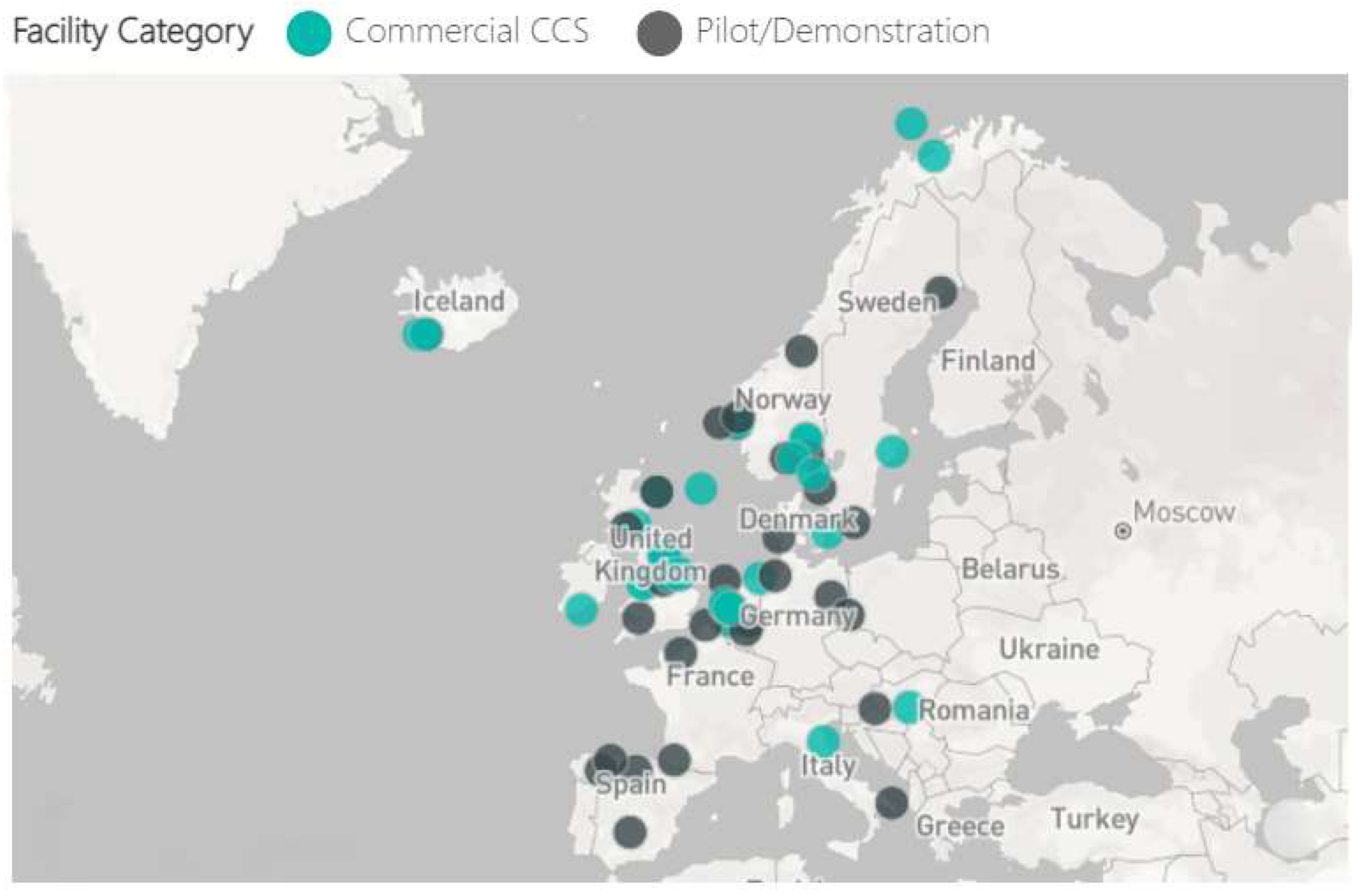
Figure 1. Visualization of the mean spatial distribution of carbon dioxide over Europe during the last period of 2021. Red and blue colors represent the highest and the lowest average values of CO2. Data were retrieved and modified from Copernicus Atmosphere Monitoring Service (CAMS).
Energies 15 05716 g001
Figure 2. (ag): European citizens completing the questionnaires regarding CO2 issues at the geological stand of the hotel.
Energies 15 05716 g002
Figure 3. Representation of potential European CCS storage sites. Green color depicts the CCS sites. Data were retrieved and modified from CO2StoP project (CO2 Storage Potential in Europe. Project No. ENER/C1/154-2011-SI2.611598).
Energies 15 05716 g003
Figure 4. Representation of the Commercial-scale CCS Facilities around Europe. Map adapted from https://co2re.co/FacilityData.
Energies 15 05716 g004
Figure 5. Questionnaire shared and completed by European citizens.
Energies 15 05716 g005
Figure 6. Excel pie charts showing the answers from the questionnaires (answers to questions 1 to 8).
Energies 15 05716 g006
Figure 7. Excel pie charts showing the answers from the questionnaires (answers to questions 9 to 16).
Energies 15 05716 g007
Figure 8. CO2 emissions vs. efficiency (y-axis: specific CO2 emissions and fuel consumption in kg/MWh). Calculation was made for a PC plant firing bituminous coal with an LHV of ~26.2 MJ/kg and carbon content of 0.64. CO2 capture rate of 90% and efficiency penalty of 10% points were assumed when CCS was added [153].
Energies 15 05716 g008
Table 1. Commercial- and Pilot/Demonstration-scale CCS Facilities around Europe. Adapted from: https://co2re.co/FacilityData.
ProjectLocationCategoryStatus/StartedOperationalFacility IndustryStorage
Hafslund Oslo Celsio-Klemetsrud Waste to Energy PlantNorwayCommercial CCS FacilityIn Construction2025Waste IncinerationYes
AcornUKCommercial CCS FacilityEarly DevelopmentMid 2020sOil RefiningYes
Acorn (Minimum Viable CCS Development)UKPilot and Demonstration CCS FacilityAdvanced Development2021–2022VariousYes
Acorn Direct Air Capture FacilityUKCommercial CCS FacilityEarly Development2026N/ANo
AcornUKCommercial CCS FacilityEarly Development2025Hydrogen ProductionYes
Adriatic Blue-ENI Hydrogen CCSItalyCommercial CCS FacilityEarly Development2026Hydrogen ProductionYes
Adriatic Blue-ENI Power CCSItalyCommercial CCS FacilityEarly Development2026Power GenerationYes
Air Liquide Refinery Rotterdam CCSThe NetherlandsCommercial CCS FacilityAdvanced Development2024Hydrogen ProductionYes
Air Products Refinery Rotterdam CCSThe NetherlandsCommercial CCS FacilityAdvanced Development2024Hydrogen ProductionYes
Antwerp@C-BASF Antwerp CCSBelgiumCommercial CCS FacilityAdvanced Development2030Chemical Production-
Antwerp@C-Borealis Antwerp CCSBelgiumCommercial CCS FacilityEarly Development2030Chemical Production-
Antwerp@C-Exxonmobil Antwerp CCSBelgiumCommercial CCS FacilityEarly Development2030Chemical Production-
Antwerp@C-Ineos Antwerp CCSBelgiumCommercial CCS FacilityEarly Development2030Chemical ProductionNo
Barents BlueNorwayCommercial CCS FacilityEarly DevelopmentMid 2020sFertilizer ProductionNo
Borg CO2NorwayPilot and Demonstration CCS FacilityEarly Development VariousYes
Caledonia Clean EnergyUKCommercial CCS FacilityEarly Development2024Power GenerationYes
Carbfix ProjectIcelandPilot and Demonstration CCS FacilityOperational2012Power GenerationYes
Cinfracap–PipelineSwedenPilot and Demonstration CCS FacilityEarly Development VariousNo
Cinfracap–Shipping PipelineSwedenPilot and Demonstration CCS FacilityEarly Development VariousNo
CIUDEN: CO2 Storage Technology Development PlantSpainPilot and Demonstration CCS FacilityOperational2015N/AYes
CODA ShippingIcelandCommercial CCS FacilityAdvanced Development2026VariousNo
CODA Terminal Onshore InfrastructureIcelandCommercial CCS FacilityAdvanced Development2026VariousNo
CODA Terminal PipelineIcelandCommercial CCS FacilityAdvanced Development2026 No
CODA Terminal StorageIcelandCommercial CCS FacilityAdvanced Development2026 Yes
Copenhill (Amager Bakker) Waste to Energy CCSDenmarkCommercial CCS FacilityAdvanced Development2025Waste IncinerationNo
DMXTM Demonstration in DunkirkFrancePilot and Demonstration CCS FacilityAdvanced Development2022Iron and Steel ProductionNo
Drax BECCS ProjectUKCommercial CCS FacilityEarly Development2027Power GenerationYes
Drax bioenergy carbon capture pilot plantUKPilot and Demonstration CCS FacilityOperational2019Power GenerationNo
Ervia Cork CCSIrelandCommercial CCS FacilityEarly Development2028Power Generation RefiningYes
ExxonMobil Benelux Refinery CCSThe NetherlandsCommercial CCS FacilityAdvanced Development2024Hydrogen ProductionYes
Fortum Oslo Varme–Shipping RouteNorwayPilot and Demonstration CCS FacilityEarly Development2025Waste IncinerationYes
Fortum Oslo Varme–Truck RouteNorwayCommercial CCS FacilityAdvanced Development2025Waste IncinerationYes
Geothermal Plant with CO2 Re-injectionCroatiaPilot and Demonstration CCS FacilityOperational2018Power GenerationYes
Humber Zero–Phillips 66 Humber Refinery CCSUKCommercial CCS FacilityAdvanced Development2028Hydrogen ProductionYes
Humber Zero–VPI Immingham Power Plant CCSUKCommercial CCS FacilityAdvanced Development2027Power GenerationYes
Hydrogen 2 Magnum (H2M)The NetherlandsCommercial CCS FacilityEarly Development2024Power GenerationNo
Hydrogen to Humber SaltendUKCommercial CCS FacilityEarly Development2026–2027Hydrogen ProductionNo
HyNet North WestUKCommercial CCS FacilityEarly DevelopmentMid 2020sHydrogen ProductionYes
HyNet North West–Hanson Cement CCSUKCommercial CCS FacilityEarly Development2026Cement ProductionYes
LEILACBelgiumPilot and Demonstration CCS FacilityIn Construction2020′sCement ProductionNo
MOL Szank field CO2 EORHungaryCommercial CCS FacilityOperational1992Natural Gas ProcessingYes
Net Zero Teesside–BP H2TeessideUKCommercial CCS FacilityEarly Development2027Hydrogen ProductionYes
Net Zero Teesside-CCGT FacilityUKCommercial CCS FacilityEarly Development2025Power GenerationYes
Net Zero Teesside-Net Power PlantUKCommercial CCS FacilityEarly DevelopmentLate 2020sPower GenerationYes
Net Zero Teesside-Suez Waste to Energy CCSUKCommercial CCS FacilityEarly Development2027Waste IncinerationYes
Norcem Brevik–Cement PlantNorwayCommercial CCS FacilityIn Construction2024Cement ProductionNo
Norcem Brevik-Shipping RouteNorwayCommercial CCS FacilityIn Construction2024Cement ProductionYes
Northern Gas Network H21 North of EnglandUKCommercial CCS FacilityEarly Development2026Hydrogen ProductionYes
Nothern Lights–PipelineNorwayPilot and Demonstration CCS FacilityEarly Development2024VariousNo
Nothern Lights–StorageNorwayPilot and Demonstration CCS FacilityEarly Development2024VariousYes
OrcaIcelandCommercial CCS FacilityOperational2021Direct Air CaptureYes
Polaris Carbon StorageNorwayCommercial CCS FacilityAdvanced Development2024Hydrogen ProductionYes
Porthos–Compressor StationThe NetherlandsCommercial CCS FacilityAdvanced Development2024VariousNo
Porthos–Offshore PipelineThe NetherlandsCommercial CCS FacilityAdvanced Development2024VariousNo
Porthos–Onshore PipelineThe NetherlandsCommercial CCS FacilityAdvanced Development2024VariousNo
Porthos–StorageThe NetherlandsCommercial CCS FacilityAdvanced Development2024VariousYes
Preem Refinery CCSSwedenCommercial CCS FacilityEarly Development2025Hydrogen ProductionNo
Shell Refinery Rotterdam CCSThe NetherlandsCommercial CCS FacilityAdvanced Development2024Hydrogen ProductionNo
Sleipner CO2 StorageNorwayCommercial CCS FacilityOperational1996Natural Gas ProcessingYes
Snohvit CO2 StorageNorwayCommercial CCS FacilityOperational2008Natural Gas ProcessingYes
STEPWISE Pilot of SEWGS Technology at Swerea/MefosSwedenPilot and Demonstration CCS FacilityOperational2017Iron and Steel ProductionNo
Stockholm Exergi BECCSSwedenCommercial CCS FacilityAdvanced Development2025Bioenergy-
Stockholm Exergi BECCS–Shipping RouteSwedenCommercial CCS FacilityAdvanced Development2025Bioenergy-
Technology Centre Mongstad (TCM)NorwayPilot and Demonstration CCS FacilityOperational2012Oil RefiningNo
UKCCSRC Pilot-scale Advanced Capture Technology (PACT)UKPilot and Demonstration CCS FacilityOperational Power GenerationNo
ZERO Carbon Humber–Keady 3 CCS Power StationUKCommercial CCS FacilityEarly Development2027Power GenerationNo
Publisher’s Note: MDPI stays neutral with regard to jurisdictional claims in published maps and institutional affiliations.

