Review

An Overview of Dynamic Inductive Charging for Electric Vehicles

1
Eaton Research Laboratories, Eaton Corporation, Golden, CO 80401, USA
2
Electrical Power and Machines Department, Faculty of Engineering, Zagazig University, Zagazig 44511, Egypt
*
Author to whom correspondence should be addressed.
Energies 2022, 15(15), 5613; https://doi.org/10.3390/en15155613
Submission received: 25 June 2022 / Revised: 22 July 2022 / Accepted: 24 July 2022 / Published: 2 August 2022
(This article belongs to the Special Issue Electric Vehicles in a Smart Grid Environment)

Abstract

:
Inductive power transfer (IPT) technology offers a promising solution for electric vehicle (EV) charging. It permits an EV to charge its energy storage system without any physical connections using magnetic coupling between inductive coils. EV inductive charging is an exemplary option due to the related merits such as: automatic operation, safety in harsh climatic conditions, interoperability, and flexibility. There are three visions to realize wireless EV charging: (i) static, in which charging occurs while EV is in long-term parking; (ii) dynamic (in-motion), which happens when EV is moving at high speed; and (iii) quasi-dynamic, which can occur when EV is at transient stops or driving at low speed. This paper introduces an extensive review for IPT systems in dynamic EV charging. It offers the state-of-the-art of transmitter design, including magnetic structure and supply arrangement. It explores and summarizes various types of compensation networks, power converters, and control techniques. In addition, the paper introduces the state-of-the-art of research and development activities that have been conducted for dynamic EV inductive charging systems, including challenges associated with the technology and opportunities to tackle these challenges. This study offers an exclusive reference to researchers and engineers who are interested in learning about the technology and highlights open questions to be addressed.

1. Introduction

Transportation systems play a very important role in our daily life. Individuals rely on transportation not only to get to work but also to shop, socialize, and access health care, among other goals. One of the most critical concerns currently is its dependency on a single energy source and a single energy carrier, where everything starts with petroleum (fossil fuels) at the top. Currently, the transportation sector consumes about 25–30% of the total energy use all over the world and over 90% of this energy cones from petroleum. This makes the transportation sector a major source of harmful emissions of greenhouse gases (GHGs) and air pollution (the first in the U.S. and the fourth worldwide) [1]. Clean transportation technologies are crucial to minimize the dependency on fossil fuels and GHG emissions. Vehicle electrification has become one of the main pillars to realize sustainable transportation and make our transportation sector more efficient, safer, and environmentally friendly. Charging electric vehicles (EVs) is one of the prime obstacles that hinders the penetration of EVs into the global market.
The first spark of wireless power transmission (WPT) started in the late 18th century by Hertz [2,3]. In 1890, radio waves are examined by Nicola Tesla to transfer power without any wires. Between 1894 and 1918, tesla built his tower which consist of a massive coil with a ball fabricated from copper on the top (Tesla tower). This tower used electromagnetic induction to transfer power wirelessly [4]. Between 2007 and 2013, a team of Massachusetts Institute of Technology (MIT) scientists reformulated Tesla’s experiments and concepts rely on electromagnetic resonance coupling. They used a coil with 60 cm diameter to transmit power of 60 W wirelessly with 40% efficiency over a distance of 200 cm [5,6]. WPT technologies can be classified into four basic categories [7]:
Near-field [8];
Far-field transfers [9];
Acoustic [10];
Mechanical force [11,12].
In near-field transfer technology, power transfers through electromagnetic fields, which stay within a short distance around the transmitter. Through this distance, the fields can be separated to transport energy over either magnetic fields by coils (inductive) [7], or electric fields by capacitors (capacitive) [13]. Among the WPT charging technologies, inductive power transfer (IPT) provides promising merits for EVs because it is noise-free, galvanically isolated, does not contain any moving parts, tolerates relatively large misalignments, and is capable of transferring high-power through a relatively large air-gap (10–40 cm) [14], which fits the ground clearance for most of the vehicles [15,16]. Table 1 shows a comparison among different WPT technologies in terms of power level, transfer distance, and operating frequency.
IPT technology provides an exemplary solution for EV charging because of the associated features characterized by: (1) safety and compatibility during harsh climatic conditions such as heavy wind, rain, and snow; (2) automation, i.e., it does not require any intervention from the driver; and (3) flexibility, as it can be implemented on the road, in public parking, private parking, at bus stops, etc. [15,16,28]. In addition, implementing dynamic inductive charging has the potential to provide unlimited driving range and zero downtime and to dramatically reduce the onboard battery size, which can help to reduce EVs’ price, size, and weight, while improving their efficiency [29].
An IPT system composes of two sides that are electrically isolated; the transmitter side contains a transmitter pad which is supplied with a high frequency (HF) AC current, compensation network, and HF inverter (10–100 kHz) controls the HF AC current, as indicated in Figure 1. IPT systems operate at a frequency ranging from 79 kHz to 90 kHz [30] (standard frequency of 85 kHz [31]) according to the SAE J2954 standard. The inverter is powered by a dc bus, which is rectified from a single- or three-phase ac supply, or a dc source, such as a photovoltaic source, can be used directly. The HF ac current generates electromagnetic fields (EMFs) that operate the receiver coil suspended in the vehicle. The coil suspended in the EV is always connected to a compensation circuit and HF AC-DC converter (rectifier) to charge the on-board battery. According to the mutual coupling between the transmitting and receiving coils, the voltage is induced in the receiver coil. Therefore, relative position between the transmitting and receiving coils performs an essential function in defining the transmission power and efficiency of overall system. The transmitter and receiver sides talk wirelessly to each other by a communication link, which is necessary for license, authentication, alignment, billing, and control [30].
There are three visions of implementing IPT technology to charge EVs:
Static or stationary charging;
In-motion, on-line. or dynamic charging;
Quasi-dynamic or opportunistic charging.
Stationary charging happens while the EV is parked for a long time, such as over-night charging and charging at workplaces, public parking, and garages [32]. In this case, the charging process starts when the transmitter and receiver coils are fully or partially aligned [33]. Dynamic charging occurs while the EV travels at high-speed, in which a transmitter coils are laid inside ground and extended for long-drawn distances. During the movement of the EV over the electrified pieces of the transmitter coils, it picks up power from these pieces to charge its storage element (battery). In In-motion charging, the transmission coils can be either single long- coil tracks or segmented-coil array that consists of sets of transmitter pad buried together [9,16,33]. In-motion charging is the most applicable process for charging EVs during driving in high-ways (long-distance and inter-city trips), because of high power requirements accompanied with restricted accessibility to stops. Quasi-dynamic charging is the process that permits an electric vehicle to charge while traveling at low speeds and during momentary pauses, such as intersections, traffic signals, and bus stops [9,34].
The “Transformer System for Electric Railways” was the first patent in 1894 that marked the beginning of the concept of electric cars being charged during movement on highways (dynamic electric vehicle) [35]. The basic configuration of the system at this time was completely similar to the IPT system, in addition to some features and improvements that were claimed in the patent, including the need to transmit high power over a large air gap distance, reduce conductive and eddy current losses, and raise the system efficiency, and it is still under research and development until now [36]. In the USA, interest in charging electric vehicles increased after the oil crisis in the 1970s, when several research teams began working on the use of vehicles that would be able to travel on highways without the need to stop to charge their batteries or fill up fuel in order to overcome the shortage of oil [35,37,38,39,40,41]. The first development of highway cars began in 1976 to confirm the technical feasibility and then to create the first model of the IPT system that transmits 8 kW of power, but this model was not fully functional [42]. Therefore, in 1979, the Santa Barbara electric bus project began, where another prototype was developed [40,41].
In 1992, the Partners for Advanced Transit and Highways (PATH) project started, in which design, laboratory and field tests were carried out for an IPT system and installed in a bus. Then, the project constructed roads and supplied power transmission systems to them and studied the potential environmental impacts. This project was able to transmit power of 60 kW over an air gap distance of 76 mm with an efficiency of 60% [43,44]. The prototype of PATH did not gain commercial popularity due to the large weight of the coils forming the power transmission system, high acoustic noise, high cost of the system construction, and high current due to low operating frequency of 400 Hz. Moreover, the distance over which the power was transmitted was small and not commensurate with the ground clearance of electric vehicles. Despite the obstacles that stopped the system from spreading, it was a good start and opened the way for researchers to develop the technology [43,44].
This paper introduces an extensive and focused review for dynamic inductive charging system, including the following:
Section 2 presents the architectures and arrangement of transmitter systems.
Section 3 presents the different compensation circuit topologies.
Power electronics converters are presented in Section 4, while the control techniques used in dynamic charging systems are introduced in Section 5, and Section 6 presents R&D and standardization activities.
Future work and challenges of dynamic wireless charging systems are presented in Section 7, then the paper is concluded in Section 8.

2. Architecture of Dynamic Inductive Pads

The dynamic inductive pad is one of the most critical parts of the system, as it is responsible for the power transmission from the source to the vehicle. A dynamic IPT (DIPT) system consists of two isolated pads: ground (transmitter) and vehicle (receiver), and each pad composed of three major components: conductors, magnetic material that acts as field concentrator, and EMFs shield. Special types of wires are used in IPT systems to reduce skin and proximity effects due to the high-frequency operation. These wires possess small ac resistance that leads to a high system quality factor and efficiency [45]. Several types of wires have been tested, demonstrated, and reported in the literature for IPT systems, such as litz wires [46,47], magneto-plate wires (LMPWs) [48,49], magneto-coated wires (LMCWs) [50,51], tubular conductors [52,53], REBCO wires [54], and Cu-clad-Al wires (CCAs) [46,55].
Flux concentrators are used to direct EMFs from the transmitter to receiver coils, which enhances the coupling performance and coefficient as well as helps to reduce leakage EMFs around the system (e.g., ferrite [56], magnetizable concrete [57], flexible magnetic [58], or nanoparticles [59]). Shields are used in IPT systems to keep leakage EMFs around the system within the safety limits identified by different international guidelines, such as the International Commission on Non-Ionizing Radiation Protection (ICNIRP). The ICNIRP 2010 has been considered for IPT systems, which recommends limits for external magnetic fields density (B) of 27 µT for humans, and 15 µT for pacemakers [60,61]. The EMF shields used in IPT systems can be passive [62], active [63], or reactive [64].

2.1. Pad Implementation of DIPT System

In most practical implementation, the charging system consists of a single transmitter pad and a single receiver pad (STSR), each connected to a compensation circuit, as shown in Figure 2a. In other applications, such as large vehicles (e.g., buses,) multiple coils are used whether on the transmitter side only, receiver side only, or both sides. Therefore, the system becomes more complex as the number of mutual coupling increases between coils [65]. The study in [16] proved that through the STSR compensation model, several compensation models can be achieved; the first is when multiple pads are connected on the transmitter side with a single pad on the receiver side. This system is called multiple transmitter–single receiver (MTSR), as depicted in Figure 2b. The second model is accessed by installing a single pad at the transmitter and multiple pads at the receiver (STMR), as shown in Figure 2c. The other model is obtained by connecting several pads on both sides and it is called multiple transmitter–multiple receiver (MTMR), as illustrated in Figure 2d.
Several pros can be gained from paralleling multiple coils, such as amelioration of the sinusoidal voltage waveform, decreasing the excessive voltage on the semiconductors, and increasing the maximum efficiency at a fixed operating frequency. A maximum transmission efficiency can be achieved through the three-coil system, in addition to achieving the rigidity of the power efficiency against load changes and a low coupling coefficient under different misalignments [66,67].

2.2. Architecture of the Transmitter Pad in DIPTs

In dynamic inductive power transfer systems (DIPTs), EVs can be charged while driving without the need to stop or wait for the charging process to complete. This technology is intended to support long-trip travel on freeways, which is one of the main obstacles for EV technology. In addition, DIPT technology has the potential to significantly increase driving range while using a smaller onboard battery [19]. Therefore, DIPTs offer a promising solution for self-driving vehicles as well as heavy-duty vehicle electrification. Dynamic charging is achieved by burying the transmitter coil into the ground and attaching the receiving coil at the bottom of the vehicle. These coils are supplied by high voltage and high frequency from an ac source. They are coupled with each other by the magnetic field when the vehicle passes over the transmitter coil to transmit the nominal power with maximum efficiency. There are some challenges that hinder the dynamic charging penetration, including the large cost of the installation, the necessity to have a separate lane for charging, which is difficult to provide in crowded cities, and the necessity for a perfect alignment to be achieved to avoid the occurrence of loss of the transported power [9]. In DIPT systems, the transmission side may have one of two types of pads: single long coil track (stretched) or segmented coil array [68].

2.2.1. Single Long Coil Track

The transmitter is a single coil with a length larger than the coil on the vehicle side. It ranges around 10 to 100 m long inside the ground track, enabling it to charge more than one vehicle at the same time [69]. The transmitter system consists of a long transmitting wire track and a transmitter station, which includes a resonant network, HF inverter, and rectifier, as shown in Figure 3. This system has several merits; for example, it is easy to control, because it is connected to one source, there is constant mutual inductance between the track coil and receiver coil when the vehicle travels over the ground path, it is simple in configuration and design, and it requires simple compensation circuits. This system was demonstrated in South Korea for public transit buses and shuttle services under the name of On-Line Electric Vehicles (OLEVs) [69,70,71,72].
On the other hand, this configuration shows some disadvantages, including the high losses and maintenance requirements [19]. Moreover, it produces redundant EMFs when the vehicle does not cover the transmitter track, and the coupling coefficient is very low, which reduces the overall transmission efficiency [73]. The transmitter track can be classified based the shape of the magnetic core into: U-type [74,75], E-type [74,75], I-type [76], S-type [36,74], ultra slim S-type [36], and X-track (cross-segmented) [77], as indicated in Figure 4. The performance of these types is summarized and compared in Table 2.
In DIPT systems, it is necessary to preserve the power from loss as well as to protect living organisms from harmful electromagnetic fields. Therefore, when using a long transmitter track on the ground side, it must be activated only when EVs pass over it, but in the event that EVs do not exist, it must be off. To meet these requirements, the long transmitter track must be divided into several sub-tracks. Each sub-track can be activated by supplying it with a high-frequency current through a switch box fed by an inverter as shown in Figure 5 [74,77]. A centralized switching track is the first type of long sectionalized track consisting of a few sub-tracks, a bundle of supply cables, and a central switching box. One of several pairs of supply cables is connected to the inverter through the switch box at a time, as shown in Figure 5a. One of the disadvantages of this configuration is that the inverter can be used to activate only one sub-track, and it requires a very large number of bundles of power cables.
The second type of long partitioned track is the distributed switching track, which consists of a few sub-tracks, a pair of common power supply cables, and several switch boxes that are connected between two sub-tracks as depicted in Figure 5b. In this type, the length of the cables is less than the centralized type, especially when using a large number of cables. Because of common power supply cables, the construction costs and conductive losses are increased. Therefore, the crossed-segmented track (X-track) was proposed, which contains auto-compensation switch boxes, segmented sub-tracks, roadway harnesses, and control signal lines, as depicted in Figure 5c. The auto-compensation switch boxes redirect current of a single pair of power cables to activate a double pairs of power cables leads. Also, the boxes can nullify the connection to obtain a silent mode, as depicted in Figure 5c [74,77]. This type has the shortest length of cables, several sub-tracks can be operated by one inverter, and the cost of cables is less than half the cost of the other two types [77]. The sub-track is made of twisted power cables, a core, and copper nets so that the electromagnetic fields under each sub-track are small and compatible with ICNIRP guidelines [61].

2.2.2. Segmented Coil Array

The segmented coil array consists of multiple coils connected to each other in series or in parallel, buried inside the ground to form the charging track, as depicted in Figure 6. As in static charging, each segmented transmitter coil is roughly the same size as the receiving coil (usually within 100 cm) [78], and has its own compensation circuit, which makes this system similar to the resonant inductive power transfer (RIPT) system [19,79]. In this type, the receiver coil is coupled with one coil from the segmented transmitter array, so only the closest transmitter to the receiver can be excited, and when the vehicle moves away from the excited transmitter coil, the excitation can be turned off. This leads to higher system efficiency and reduces the leakage magnetic field around the system. Moreover, having a compensation circuit for each segmented coil makes the design of the overall length of the track more flexible [69,80]. This system is more complicated in structure because it needs many compensation components, inverters, and transmitter coils, which leads to high material costs. To reduce this cost, the system can be designed to have a string of coils sharing the same power electronic converter.
Another challenge for this system is the horizontal distance between the transmitter coils array. The segmented transmitter coils are made in small structure and separated by a large distance in order to eliminate the self-coupling. Because of this, the magnetic field decreases at the points that are in the middle of the distance between the transmitter coils, which significantly reduces the power potentially to zero when the receiver coil is centered between two transmitter coils. This leads to power pulsation while the receiver coil is in motion. To minimize the power pulsation, the transmitter coils can be placed very close to each other, but the design of the resonant circuits will be affected by the self-coupling of coils and a large number of coils will be needed to electrify the same distance [69,73].
In [78], the value of power pulsation remains within 50% of the maximum power when the distance between the transmitter coils is about 30% of the transmitter length. A comparison between several variant configurations of the segmented coil array is presented in [81]. Although both the long coil track and segmented coil array have merits and demerits, it is better to use the segmented coil array, as the use of multiple coils is more complicated in installation and operation, but it can be technically solved easily. The simplicity of use and installation of a single long coil is followed by the harmful emissions of magnetic fields and decreases the efficiency of the system [73].
There are two main types of feeding arrangements for a dynamic charging system when using ground-based segmented coils. In the first arrangement, each segmented coil is connected to a separate HF inverter, as shown in Figure 7a [32,82]. This inverter activates and deactivates the system when the vehicle is aligned or not aligned with the corresponding segmented coil, respectively. This arrangement allows the use of low-power inverters, as well as connecting each segmented coil to an independent compensation circuit, which improves the performance and reliability of the dynamic charging system. This system is simple in construction, but it causes a significant safety risk as it operates high-power and high-voltage dc lines. In addition, it requires many inverters and sensors to operate.
The other arrangement is achieved by feeding a set of segmented coils through a common HF inverter. A switching device and an independent compensating circuit are connected to each segmented coil, as shown in Figure 7b [78,83]. The switching device activates and deactivates the system when the vehicle is aligned and misaligned with the segmented coil, respectively. This system avoids the safety risks resulting from the other arrangement, shown in Figure 7a, due to using a high frequency that achieves individual transmitter segments extended from the transmitter power station. The negative side of this system is the increase in the total length of the track by increasing the number of charging segments and thus increases to the total cost, so the practical number of charging segments is limited [84]. This arrangement is characterized by the fact that it uses one inverter, but a large number of switching and sensing devices are needed [75].
Sensor vehicle detection is a device used for several purposes, including detecting the position of the EV while entering the charging lane and detecting misalignments. Despite the difficulty of implementing detection systems in multi-lane highways, and their use increasing the cost of the dynamic charging system [85], a detection system was implemented in [86] which uses multiple coils at the transmitter and receiver. This detection system is used to detect the position of the EV where the coil is energized towards the receiver using a high frequency current which generates an induced voltage as the vehicle passes. This voltage is measured to detect the presence of an EV and thus turns the transmitter coils on and off. In [87], receiver position sensing in a DIPT system for EV charging was studied. Considering the exotic behavior for the input impedance of resonator arrays, it was used to determine the place of the receiving coil by sending a signal at a suitable frequency to the first array resonator and then measuring the output current. In [88], an alternative that does not have an EV position detection sensor (sensor-less) is tested by calculating the phase angle between voltage and current that reverses the position of the vehicle’s rim.
The use of the two above-mentioned arrangements to feed a set of segmented transmission coils leads to an increase in the complexity and cost of the DIPT system. To get rid of these obstacles, a different arrangement was proposed, which is the reflexive segmentation, as in [80]. This arrangement uses a common high-frequency inverter to feed a set of segmented transmission coils that are connected in parallel. This system does not need to use switching and sensing devices, as shown in Figure 8. In this proposed system, no resonant capacitors are used to compensate for the transmitter self-inductance, so the conjoint influence of the transmitter self-inductance and feeding operation with high frequency at uncoupled circumstances makes impedance of the coil too large. So, the current passing through the uncoupled transmission coils is small and thus the resulting field is weak. When the transmitting coil is coupled with the receiving coil, the impedance of the receiver is reflected to the transmitter coil. This impedance brings the transmitter coil into resonance at the operating frequency. Thus, the generated EMF by the transmitter increases and therefore, the transmitted power increases [75,80].
There are other types of DIPT system feeds with a segmented transmitter, and each uses a different method to control the charge of the individual segment inside the transmitter track. One of these types is shown in Figure 9a, where the power is transferred from the transmitter power station through a magnetic coupler to a specific charging segment, instead of direct connection as in the other arrangements. The activation and deactivation of a charging segment is controlled by a simple bidirectional ac switch [89,90]. Another type is introduced in [32,77], as shown in Figure 9b, which uses a two-turn transmitter path configuration where switching boxes can be used to change the direction of the current, when it passes in one of the turns, in order to activate or deactivate the magnetic field in the area around the specified transmitter segment in the path. Thus, each segment can be controlled individually and independently. The number of plugins required is small, but all the charging segments are connected in series and all switching boxes are required to be rated at the full current rating of the transmitter track.
There are three major obstacles to the above-mentioned systems which make them not exemplary for dynamic charging applications: (1) Because of the vibrations and pressures caused by the movement of trucks, buses, and vehicles, roadways are unfavorable places for the presence of electronic circuits, as there is difficulty in the process of maintaining or replacing any component, and these operations are very expensive. It is necessary for the system to continue to work even if one or more transmitter segments are found to be down. (2) Except for the system shown in Figure 9a, the remaining systems do not have any means of isolation between the power supply and the charging segments, which increases the possibility that the entire transmission track will fail if any failure occurs in a single charging segment. (3) Most dynamic charging systems are designed to operate at a frequency of 20 kHz, which is contrary to the recommendations of SAE J2954 to operate at a frequency of 85 kHz [31]. Therefore, dynamic charging models will face several hurdles to be able to operate at a frequency of 85 kHz such that the power source is required to be rated at hundreds of kVA due to the high transfer power demanded for electric cars. It is also difficult to find semiconductor switches which can operate efficiently at this power level as well as at such high frequencies: the IGBTs can handle the high-power rating only at lower frequencies while the latest MOSFETs devices can handle the higher frequency only at reduced power ratings. (4) All the aforementioned systems do not contain any kind of communication systems between the electric vehicle and the infrastructure, which may lead to an increase in the load on the electrical network during peak times or traffic congestion due to charging a large number of cars at the same time. The power is lost in the use of auxiliary devices such as entertainment and cabin heating/cooling [82].
In [82], a double-coupled system has been suggested to feed the DIPT system, which consists of a high-frequency power track buried underground and feeding an “intermediate coupler circuit” (ICC) at the specified segment, as shown in Figure 10a. An ICC includes a controlled rectifier to convert HF ac voltage to dc, which feeds an HF inverter that controls the transmitter segments, as shown in Figure 10b. The ICC allows independent control of each transmitter segment. The system is so named because the transmitted power is coupled twice, once between the power source and the ICC, and once between the ICC and the transmitter segments. This system offers significant reduction in the the losses in the transmission track, since it can operate at a low frequency, while the transmitter segment is operated at a high frequency, which improves the efficiency of the system. In addition, there is isolation between the transmitter segments and power source, and the system helps to reduce the impact of dynamic charging on an electrical network at peak times. This system faces challenges such as the high cost of power electronics and low reliability due to the use of a central power supply unit for the entire system [32].
Many researchers have conducted studies on the segmented coil array as a transmitter to realize the optimal operating conditions in terms of transmitting the maximum power at the highest possible efficiency commensurate with the ground clearance of EVs. In this type, the transmitter consists of multiple pads with configurations similar to the ones used for static charging, such as circular, rectangular, double-D (DD), DDQ, DQD, and bipolar. In [91], a method was proposed to choose the length of the transmission coil taking into account the vehicle speed, power consumption per kilometer, power loss, and charging efficiency of the system. A long transmitter coil, rectangular receiver coil, and LCC-S compensation topology were used. The transmission power and efficiency were calculated, then the minimum value of the transmission coil current was inferred from the maximum value of the charging power. Power transmission has been achieved with an efficiency higher than 85%. In [92], a DD segment transmitter array was proposed. The study explored the optimal dimensions and best horizontal separation between the transmitter pads to improve the system properties.
A double-spiral repeater was used in [93] to improve the power transmission efficiency, increase the transmission distance, and increase the variation in the linear misalignments. When optimizing the system parameters, represented by the horizontal distance between the segmented coils, transmission efficiency, number of segmented coils, and load conditions, an efficiency of about 60% was obtained at a transmission distance of 35 cm and 81% at a distance of 10 cm. In [94], the relationship between several parameters such as path length, operating efficiency, and vehicle speed were studied and analyzed. The optimum path length at which the highest possible transfer efficiency is achieved was estimated. In [82], a double-coupled system was used for the segmented transmitter dynamic charging system. An intermediate coupler circuit was used to control transmitter segments, the system was operated at a frequency of 20 kHz, and 5 kW power was transmitted with a maximum efficiency of 92.5%. In [95], the performance of segmented coils was improved and a stable charging method was identified for high-power applications. A mixture of coils was used in the track, where a rectangular coil was combined with a DD coil and then a rectangular coil side by side. These coils were excited to improve the number of active transmitters and reduce the variation of the output voltage; a 2.5 kW power transmission with 85% dc-dc efficiency was achieved.
In [96], a new transmission coil structure was proposed whereby bipolar coils are used symmetrically on adjacent unipolar transmitter coils. This leads to the natural separation between the bipolar and unipolar coils. This configuration has the potential to reduce the self-coupling between adjacent unipolar coils, thus facilitating the design of the compensation circuit. Moreover, this design shows a better stability for mutual coupling between the transmitter and receiver during the vehicle movement, which makes it suitable for dynamic charging. The power transmission was achieved with an efficiency of up to 90%, with a fluctuation of power within ±22.5%.
In [69], six side-by-side coils connected in parallel were used, and the distance between them was reduced to a very large extent to reduce the occurrence of power fluctuations. Therefore, the coil self-coupling coefficient was taken into account in the circuit. The six coils were fed at the same time from a common inverter in order to simplify the power electronic circuit. Each segmented coil at the transmitter side had an independent LCC compensation circuit. This design helped to reduce the voltage pressure on the compensation capacitors and adjust the path length. It also helped to transfer a power of 1.4 kW with a dc-dc transmission efficiency of 89.7%, and the fluctuations in the power were equal to ±2.9% of the average power. A two-segment LCC compensation circuit was built up and fed from two different inverters in [97]. The effect of using the LCC compensation and the inter-coupling on the neighbors’ coils in the transmission path was studied. A 2.34 kW power transmission with a dc-dc efficiency of 91.3% was obtained.
In [98], a multi-parallel LCC compensation circuit on the transmitter was employed so that all segmented transmitter coils were fed from one inverter. This design allows for automatic distribution of power between different segmented coils. Moreover, an attached LCC circuit was used to control the transmitter current, resulting in reduced magnetic field emissions and power losses. An improved LCC circuit which is fed from a common inverter was proposed in [99] to obtain stable and highly efficient output power under variable mutual induction conditions. A steady-state study was performed under different mutual inductance and load circumstances to determine the soft switching circumstances, required output voltage, and regular power transmission. The results showed that changing the mutual inductance by a factor equal to two leads to a reduction in the transmitted power by less than 20%. In [100], a set of circular coils connected in series were used to make the transmission track. The power of 6.6 kW was transmitted over a 16.2 cm air gap with an efficiency of 85%.
In [101], passive shielding was used where a metal plate was extended inside the ground and this plate was electrically connected to the vehicle through metal brushes. These brushes can be controlled by making them not touch the ground when the vehicle is in motion, but when passive shielding is required, it is connected to the ground plate. In [63], an active shielding coil was placed at both the transmitter and receiver side far enough from the main magnetic coupling path. This type of shielding has been tested on U-Type and W-Type magnetic cores. Three innovative methods have been applied to cancel the leakage magnetic field on the I-Type core: the independent self EMF cancel (ISEC) method, 3 dB dominant EMF cancel (3DEC) method, and linkage-free EMF cancel (LFEC) method. The leakage EMFs were decreased to a level less than the permissible safety limit.

2.3. Architecture of the Receiver Pad in DIPT

In DIPT systems, the receiver pad is expected to be the same as the one used for stationary charging for interoperability operation and reducing the in-vehicle components. The receiver side assembly may contain one or more pads, depending on the vehicle class. Figure 11 illustrates two different ways to implement the receiver pad, either a single pad, as shown in Figure 11a, which is convenient for small light-duty EVs, or multiple pads, as shown in Figure 11b, which might be needed for medium- and heavy-duty EVs to meet their power requirements. Using multiple receivers helps to scale-up the system to support different types and sizes of vehicles. For instance, a 50 kW system can transfer a maximum power of 50 kW to an EV with one receiver. Moreover, it can transfer a maximum of 100 kW to a larger vehicle with two receivers. Each receiver is compensated by a separate compensation network to achieve the maximum transmission efficiency [102].
In [103], a magnetic coupling structure with a dual receiver coil was proposed by analyzing the power supply characteristics in the process of DWPT for EVs with fluctuations of coupling factors between electrical energy coupling mechanisms, current, and voltage at the on-board receiver end and system transmission power. An experimental platform with a power level of 15 W, a 15 cm × 15 cm circular coil structure, a 3 cm air gap between the transmitter and receiver, and a resonant frequency of 85 kHz was built for the DIPT of EVs. It was verified that the dual receiver magnetic coupling mechanism can reduce the output voltage fluctuation and output power fluctuation caused by the switching of the transmitter during EV travel. In [104], the conventional circuit model-based analysis for a one-receiver system to investigate a general one-transmitter multiple-receiver system was extended. The influence of the loads and mutual inductance on the system efficiency was discussed. The optimal loads, the input impedance, and the power distribution were analyzed and used to discuss the proper system design and control methods. Finally, systems with different number of receivers were designed, fabricated, and tested to validate the proposed method. Under optimal loading conditions, an efficiency above 80% was achieved for a system with three different receivers working at 13.56 MHz. In [105], an extensive theoretical analysis is conducted on the influence of the cross coupling and its compensation in multiple-receiver WPT systems. The optimal load reactance was analytically derived and verified for both the two-receiver systems and the general multiple-receiver systems. It was shown that the reduction in the overall system efficiency because of the non-zero cross coupling can largely be recovered by having the optimal load reactance. The other important system characteristics such as the input impedance and power distribution can also be preserved.
In [106], a three-coil compensation system was studied in the case of MTSR, where S-S-S compensation was used to realize the constant voltage (CV) properties. The three-coil S-S-LCC compensation was also analyzed to enable the constant current (CC) properties. In both of these compensation cases, the zero-phase angle (ZPA) can be obtained. The authors in [107] studied the Z-source grid when connected to a three-coil MTSR system with S-S-S compensation. The Z-source grid can work over a large range of voltage where it can either buck or boost the voltage according to the type of topology. Because of its varying shoot-through cases, it can operate without the need for dead time of switches, which leads to raising the total reliability of the converter. In [108], the same previous topology (S-S-S) was used with a three-phase inverter, by inserting a capacitor in each phase. The MTSR is not only used to transfer power, but it is also used to transmit information [109], and this type can be used with the basic compensation for the dynamic charging of EVs [110,111]. In [112], two compensations were connected in series to the transmitter side, and the LC compensations were connected in parallel to the receiver side as an example of the MTSR system. The resonant frequency is tuned by adjusting the LC connection to achieve a high voltage because the parallel LC connection works as a current source at the resonant frequency. Thus, it can be said that it is appropriate for increasing the voltage.
Power can be transmitted to multiple systems at the same time by using the free positioning STMR system with a compensation topology, where the entire transmitter surface is utilized to transmit the power without any obstacles on the orientation of the receiver. In [113], the three-coil array texture was taken advantage of in the application of the free positioning style. This style gives the ability to charge 1–3 smartphones with ease of application and use [16]. The STMR system can be used in some applications such as Maglev trains with a transmitter connected as series compensated [114] and multi-level converters used in a bidirectional charging system with a three-coil LCL compensation topology [115]. An MTMR system was used to enlarge the magnetic communication range [116] and to reach a maximum efficiency at optimal power using the LCL-T compensation topology with a parallel inverter [117]. In [118], wireless power transmission while driving from several coils on both sides (MTMR) was studied using an LCL-LCL compensation circuit. Although the MTSR and STMR systems increase the size and cost of the charging system, they provide some merits such as supplying high voltage and power and improving the signals form.

3. Compensation Networks

Compensation capacitors are used in IPT system to compensate for the large leakage inductance in the system associated with the large air gap, that aids to improve the transmission power and efficiency of the system [119,120]. In addition, resonance networks help to reduce the apparent power drawn from the source by providing the reactive power requirements, achieving unity power factor (PF) process by obtaining zero phase angle (ZPA) to avoid bifurcation analysis and enables electronic devices to operate with soft switching [121], and achieving constant current or constant voltage charging, which means when the root mean square value of the input voltage is fixed, then either the output dc current or dc voltage is fixed [68].
On one hand, compensation topologies can be divided into basic (classical) resonant topologies and hybrid (composite) resonant topologies as illustrated in Figure 12. The four basic compensation topologies consist of a single capacitor connected either in series or in parallel on both sides of the system; they are series–series (SS) [122], series–parallel (SP) [123], parallel–series (PS) [124], and parallel–parallel (PP) [125]. Hybrid compensation topologies are a combination of LC circuits; they include LCC [126], CCL [127], LCL [128], LCL-P [129], S-CLC [130], LCL-LCL [131], LCCL-LCCL [30], and others.
On the other hand, compensation circuits can be classified according to the number or location of resonance elements. Considering the number of elements, when one resonant element is placed on the transmitter side or receiver side only, it is called single-element resonant (SER). When two or more elements are placed on each side, as in the basic and hybrid topologies, it is called multi-element resonant (MER) [119]. If the classification is based on the location, the resonance elements can be placed on the transmitter or receiver (one side), on both sides (double side), or placed when there is more than one transmitting or receiving coil (multi-coils) [132].

3.1. Single-Element Resonant Topologies

Single-element resonance (SER) is used as one of the compensation types for the transmitter and receiver. In SER system, one capacitor is connected in series or in parallel either to the transmitter or receiver, as illustrated in Figure 13 and highlighted in red boxes. When the system operates at the angular resonant frequency, the power transmission capacity to the secondary side and system efficiency increase. Series compensation is more appropriate in case of static coils as in stationary charging or in dynamic charging with a segmented transmitter coil, because they are high current systems. Parallel compensation enables higher voltage and lower current than series compensation [132].
In [133,134], the compensation circuits that include a capacitor in series or parallel to the primary or secondary side were studied and compared based on the power factor, current gain, and voltage gain. It was concluded that when using a capacitor in series with the primary coil, the power factor reaches a high value close to unity for any value of the quality coefficient of the secondary circuit (Q2). As for the other three compensation cases, when Q2 has a normal value, the value of the power factor is low. When the load is very heavy, the power factor value reaches the unity when a series capacitor is used towards the primary coil side. However, when using a capacitor in parallel to the secondary coil, the load must be very light to achieve unity power factor. This shows that series compensation is unable to meet the system requirements under all circumstances [119].
In [135,136], the total inductance of the primary side seen by the capacitor was reduced by placing a transformer behind the capacitor, and in [137], the secondary side capacitor was used to develop simple impedance matching techniques. Neither of the methods addressed in [135,136,137] are suitable due to the high capacitor ratings, dependency of load, and primary current, which are not acceptable in high-power applications. In [138], the authors concluded that the insertion of a series capacitor improves only the imaginary part of the primary and secondary impedances, thus improving system efficiency. However, the efficiency depends on both the imaginary and real parts of the secondary impedance and also depends on the real part only of the primary impedance according to Equation (5) mentioned in [119]. Therefore, the insertion of a capacitor in series with the primary side does not improve the efficiency. To improve and increase the efficiency of the system, a capacitor must be inserted in series with the secondary coil and its value must be chosen very carefully to compensate the secondary inductance (L2) at resonance. That said, it can be concluded that compensation by using a single capacitor in series or parallel is unable to maintain a constant transmitter current under various loading or coupling conditions.

3.2. Basic Topologies

SS, SP, PS, and PP are the basic compensation topologies in which the letter S or P represents the way the compensation capacitor is connected. The letter S stands for series connection, and the letter P stands for parallel connection. The first letter expresses the connection of the capacitor towards the transmitter, while the second letter expresses the connection towards the receiver [139]. In this topology, one capacitor is connected to the transmitter and another capacitor is connected to the receiver, as depicted in Figure 14 and highlighted in red, and therefore it is called two-element resonant topology (TERT). The motivation to develop the wireless charging system with the introduction of compensation topologies comes from a study conducted by researchers from the MIT in 2007 [6]. This study demonstrated that the power transmission efficiency and the air gap distance are greatly improved when magnetic coupling coils are used with compensation circuits operating at resonance.
The basic compensation topologies are studied in detail in [32,125,140,141]. In [140], the series compensation topology with a three-phase bipolar coil is used to transfer power of 50 kW with a dc-dc efficiency of 95% over a 150 mm air gap distance in a perfect alignment condition. In [125], two techniques, with a receiver series capacitor or receiver parallel capacitor, were studied to be used as a voltage converter with the highest efficiency and operating conditions at different frequencies. In [141], SP and SS topologies analysis was conducted to improve the efficiency of the wireless charging system when using asymmetric coils. This study was conducted on two systems: the first when the primary and secondary coils are identical (symmetrical), and the second when the primary and secondary coils are different in size (asymmetrical). It was concluded that in the case of asymmetrical coils (primary is larger than secondary), SP topology gives higher transmission efficiency than SS topology. Choosing the values of capacitance and inductance depends mainly on the quality coefficient, coupling coefficient, and transmitter and receiver topology [142]. Using a parallel capacitor on the transmitter side is rare due to complexity of calculations, reliability of the load, coupling coefficient, and large input impedance [143,144].
Expressions used to calculate transmitter capacitor (C1) at the resonant frequency ( ω ) and total impedance (ZT) of the system seen by the source are presented in Table 3. In case of SS compensation, the value of the capacitance is constant regardless of the change in load or coupling factor. It also has the ability to regulate the weak output voltage, and this is the biggest advantage of the SS [145,146]. On the contrary, the SP compensation depends on the coupling coefficient and requires a large capacitor with the transmitter to achieve high coupling coefficient [120,142]. In SS and SP compensations, the overall impedance reduces, resulting in high current fed from the source and going to the load. In compensation of PS and PP, the overall impedance raises with the misalignment, resulting in a significant reduction in fed and absorbed currents. When working at the resonant frequency, the optimum state is reached, and the nominal power is transmitted with the highest efficiency. When changing the resonant frequency while resonant capacitors are fixed, the power and transmission efficiency are negatively impacted.
In SS compensation, the value of the capacitance depends on the resonance frequency and the value of the transmitter inductance (L1), but the SP compensation depends also on each of them in addition the mutual inductance (M) [147,150]. In PS and PP compensation, the transmitter capacitance depends not only on the coupling coefficient and inductance but also on the load impedance as indicated in Table 3. This table also shows expressions of the total impedance seen by the source when there is a misalignment between the transmitter and receiver coils. In the SS and SP topologies, ZT decreases with misalignment, while in PS and PP, ZT increases with misalignment causing a rapid decline for both the supplying and absorption current. To improve the transmission efficiency in the PS and PP topologies, an additional series inductance is added to form LCC or CCL topology to improve the control of the inverter current flowing in the parallel compensation circuit. This inductance increases the converter size and thus the cost of the system is high [142]. In PS and PP topologies, the input impedance is large, which necessitates a high driving voltage to transmit a sufficient amount of power [151]. These topologies are characterized by a high power factor and efficiency at a small mutual induction and a large range of load change [95,152]. These topologies operate at a relatively large distance with the same operating frequency at low power levels [153].
The PP topology is more suitable for high-power applications [147,154]. When using parallel compensation on the secondary side, the characteristics of the current source are proportional to the battery charge, while a large current is generated in the primary side when using parallel compensation [155]. This topology requires a large primary capacitance when the coupling factor and secondary quality factor are small. High coupling factor or quality coefficient of the secondary, requires small primary capacitance [120]. The PP topology configuration has several disadvantages including a low power factor, high load voltage in the case of secondary parallel, and high source current requirement in the case of primary parallel [156,157]. In Ref. [158], a comparison was made between the four basic topologies. It was concluded that SS compensation of IPT system gives the best efficiency at the operating frequency of 1 MHz [151]. It also transmits a higher power than the SP compensation at the same operating [159]. SP compensation is slightly higher in the transmission efficiency [160].
A comparison was made between the four basic topologies in Table 4, including total impedance, sensitivity of misalignment, dependency on the coupling factor and load impedance, load independent output, efficiency, proposed power level, inverter device voltage rating, inverter device current rating, advantages, disadvantages, and proposed applications.

3.3. Hybrid Topologies

In addition to the four basic compensation topologies, there are other topologies that include combination of LC elements, which is called hybrid topologies, as indicated in Figure 15. In these topologies, more passive elements are used to realize the advantages of both series and parallel connections and avoid the drawbacks of the basic topologies. Hybrid topologies can be obtained by adding inductance in series or in parallel, or a group of capacitances and inductances connected, as in Figure 15a–e. It can also be achieved by means of a mixture of two or more capacitors connected to one side as in Figure 15f–l. System efficiency can be improved over the entire range of the loading and coupling by using compensation circuits such as LCC-LCC and LCL-LCL. The presence of additional inductances and capacitances in the hybrid compensation leads to an increase in copper losses compared to SS topology, due to the leakage resistance of the additional capacitances and inductances [162]. The LCC-LCC and LCL-LCL compensating circuits are good choice for battery charging due to their ability to operate as current source at the receiver when operated with a voltage source inverter at the transmitter side [163,164]. In [163], both sides the LCC compensation circuit were analyzed, and it was concluded that when the input voltage is constant, the output current is constant. Zero current switching can also be realized when tuning the LCC circuit. This compensation circuit (LCC-LCC) works to compensate the reactive power at the receiver in order to achieve unity power factor operation. This type of compensation is independent in terms of loading conditions and coupling coefficient [165,166].
The drawbacks of the LCC-LCC compensation topology are represented by its large size and number of passive components, which increase the overall system cost and size [163]. However, the features realized by LCC-LCC topologies in terms of high efficiency, independency of the loading characteristics, low current stress in the inverter, and insensitivity to misalignments, make it the most commonly used in IPT system [163,166,167,168]. When LCC is used at the transmitter, the receiver can be connected to either serial or parallel compensation. Parallel compensation is commonly used because of its rigidity when changing the load [165]. To increase the voltage to large values at high power levels and to ensure continuity of conduction, series compensation is used at the receiver side, which requires a large bridge rectifier capacitor [32,166]. In [165], LCC compensation was used and characterized by small rectifier losses and high system efficiency (higher than that produced by parallel compensation). Using series compensation achieves voltage stability and blocks the dc component of the input voltage by a series-connected capacitor, but the use of a large high-frequency current during series compensation generates a large voltage on the capacitor [169]. A mixture was made between series compensation and LCC compensation with the addition of two switches, one to the sender [170] and the other to the receiver [168], in order to obtain the LCC-S topology. In [171], a comparison was made between SS and LCC-LCC topologies. It was concluded that under ideal loading conditions, the LCC-LCC compensation is less sensibility to the change of coupling factor, the stresses on capacitor voltage and current are smaller, and the efficiency is higher than that of SS compensation at different misalignments.
Another type of compensation (LLC) was used to ensure high transmission efficiency and a lower VA rating, which is used at frequencies above 1 MHz at the transmitter [172]. In [173], LC-LC compensation analysis was performed and a transfer efficiency of 92% was reached. In [174], the use of S-CCL compensation was proposed, which operated at an efficiency of 93%. By comparing the S-CCL compensation with the S-SP compensation, it was found that the efficiency of the S-SP compensation is fairly stable and is not affected by the change of the mutual inductance value. In [150], SP-S compensation was studied, through which a stable output power could be obtained in cases of significant misalignment. This compensation is used in applications that allow misalignment to occur, such as charging the batteries of mobile systems. In [175,176], an S-SP compensation was proposed which gives good output stability and lower circulating losses. This compensation is suitable for applications that need high power.
In [177], a comparison was made between SS and LCCL compensation topologies, where current and voltage stresses, output power, input impedance, and voltage gains were studied and analyzed. A 2.4 kW model was used to conduct this study. It was concluded that the efficiency of SS compensation is higher in high-power applications, while the efficiency of LCCL-S is higher in low-power applications. The results also showed that the SS compensation is more sensitive to the load change and less sensitive to the secondary compensation capacitance change. In [128], a wireless charging system with double LCL compensation circuit was studied, where 7.36 kW was transmitted with an efficiency of 95.8%. Circular coils with ferrite cores were used. The use of LCL-LCL compensation led to achieving the greatest continuous excitation for the transmitter terminals and achieving the unity power factor of the receiving terminal.
In [178], a T-type compensation circuit was used which reduced the power fluctuation in the dynamic charging system. The T-type compensation keeps the power fluctuation at less than 6% of the average output power, and the dc-dc efficiency is up to 85%. In [130], a wireless charging system with the use of S-CLC compensation was studied. This compensation makes it easy to achieve zero phase angle and zero voltage switching and obtain a stable output voltage. This compensation was compared with the LCC-LCC topology, and it was found that S-CLC needs fewer components, resulting in a lower system cost, lower volume, and lower power density. In [179], SS, double-inductor -series (LCCL-S) and double-capacitor output characteristics are analyzed. The changing of voltage gain is realized in LCCL-S compensation without extra ingredients, and the system is as yet in resonant condition.
The hybrid topologies are compared in Table 5 in terms of cost, size, features, drawbacks, and proposed applications. Another comparison is shown in Table 6 between the basic and hybrid compensation topologies, considering other parameters such as frequency (f), output power (Po), coupling factor (k), efficiency (η), air gap, and coupler type.

4. Power Electronic Converters

Power electronics represent a cornerstone in the wireless charging process for electric vehicles. It is necessary to work on improving the performance of the power converters in order to maximize the efficiency of the system. Power converters depend on the type of compensation topologies and also depend on the applications of the wireless charging system. Initially, IGBT-based push–pull converters were used to complete the conversion process, but with the development of MOSFET technology when working at medium voltages from 60 volts to 1200 volts, and increasing the frequency of switching, the main dependence to complete the conversion process becomes on the full-bridge MOSFET as a power converter [189,190]. To complete the transfer of power from the network to the electric vehicle, this requires four conversion stages, as shown in Figure 1: a diode rectifier and power factor correction (PFC) and HF inverter connected to the transmitter; and a diode rectifier and a back-end converter are placed on the receiver side. Table 7 lists these conversion stages, used topologies and required control.
Power converters can be classified into two basic categories based on the location: transmitter-side and Receiver-side conversion. Transmitter-side conversion can be divided into single- or dual-stage; while the receiver-side conversion can be conducted by rectifier only or rectifier and dc-dc converter, as depicted in Figure 16.

4.1. Transmitter-Side Conversion

The converter located on the transmitter side converts the ac power with 60/50 Hz frequency coming from the network into a high-frequency ac power. Two approaches exist for this conversion stage: (1) convert low-frequency ac to HF ac power using a single ac-ac converter (single-stage) considering matrix converters; (2) convert low-frequency ac to dc, then dc to HF ac, which is called dual-stage power conversion.

4.1.1. Dual-Stage Converters

In this method, the low-frequency ac power is rectified to dc power, and then a full-bridge inverter is used to convert the dc power to a high-frequency ac power [68]. Inverters are used in wireless charging systems because they are compatible with the presence of one coil or several coils, they provide researchers with different ways to control the activation and deactivation of the power pads, and they come with different levels of implementation complexity.
The most common types of inverter arrangements used in DIPT are voltage source single-phase, three-phase, or multi-phase inverters [76,101,191,198,199,200,201], current source push–pull [202,203], and class EF structures [195] as shown in Figure 17. The full-bridge and multi-phase structures control the phase shift while the rest provide the duty ratio control for the flow of power. The inverter topologies are presented in Table 8 with the segmentation controls and the complexity of the implementation.
When the transmitter has a parallel compensation, it is better to use a current-fed converter, but if the compensation is series to the transmitter, it is better to use a voltage-fed converter. Voltage-fed converters have high reliability, great efficiency, and the dynamic response is faster. A voltage-fed converter can be converted to a current-fed converter by turning on the current controlled mode or by connecting a series inductance either on the transmitter side forming LLC compensation or connecting it with the dc link comprising the current-fed topology [119]. The power amplifier is used when the operating frequency is between 10 kHz and 10 MHz. There are many types of amplifiers, which are class A, C, D, E, and AB. Among these types, class D and E are distinguished by their ability to give high efficiency at these frequencies [207]. The use of a full-bridge converter is better than a half-bridge converter, because it is characterized by its high potential for controlling.
The researchers in [208] utilized two H-bridges converters at the receiver and an active H-bridge at the transmitter: one of the receiver H-bridges was used to control the battery charging current, while the remining H-bridge contained a dc-supply to feed active power to the load battery. Thus, 50% of the power reaching the battery was provided by the exterior dc supply (on board) and the remining power was fed by the magnetic coils. This method is complicated and requires an exterior dc supply carried by the vehicle. This will append extra cost, weight, and size to the vehicle. A step-down high frequency transformer is suggested in [100]. It achieves safety and galvanic isolation at the transmitter and enhances efficiency of the transmitter-side inverter. This enhancement is realized by considering low current and high voltage, which decreases the conduction loss of the inverter. The system contains a dual-stage converter and a high-frequency transformer in the transmitter; on the other side, there is a full-bridge diode rectifier to suit the level of battery voltage.
Figure 18 shows most of the converters used in the wireless charging system at high frequency. Compensation circuits are used to maintain a specific value of voltage and current at the load even if the coupling coefficient between the primary and secondary pads changes or when a change in the load occurs. In this case, these compensating circuits are called a power conditioner. The power conditioner consists of a dc-dc converter with a soft output filter and a diode rectifier.

4.1.2. Single Stage Converters

Some single-stage converters cannot implement full variable frequency operation despite their uncomplicated configurations. As for the dual-stage converter configurations, it requires the use of a large dc-link capacitor and a huge filter inductance in order to be able to regulate the voltage and frequency, which leads to an increase in the total cost and reduced reliability due to the use of these bulky passive components [209]. The matrix converter (MC) was developed by the authors in [210]. Since then, it has been used in various applications such as induction machines, airplane systems, photovoltaic energy systems, and others [211]. Therefore, it is preferable to use it due to its compact design, which provides energy conversion through a single stage, which leads to the dispensation of the presence of huge storage components and dc-link circuits [212]. MCs comprise a group of bidirectional semiconductor switching devices that connect the three-phase source to the load. They convert the uncontrolled low frequency ac inputs (constant voltage amplitude and frequency) into a high frequency ac output (up to 85 kHz) that can be controlled (changeable voltage amplitude and frequency) directly without any additional conversion stages.
In [213], a single-stage transformerless buck–boost inverter was proposed to directly achieve dc to ac conversion regardless of the relationships between its dc-link voltage and peak ac output voltage. The proposed inverter is an equivalent replacement of a conventional boost converter cascaded with an inverter, while the former features simpler circuit structure, lower cost, smaller volume, and straight-forward implementation. The analysis based on its state space average model indicates that the stability of the proposed inverter is dependent on the value of its duty cycle. Fortunately, this issue can be addressed by a well-designed outer voltage-loop plus inner current-loop controller. A traditional single-phase converter for WPT applications is introduced in [148]. SS and SP compensation circuits were discussed, and it was deduced that it is preferable to use SS compensation rather than PS compensation in high-power applications, despite it having larger leakage inductance at the receiver side. In [214], single-stage converter topology is presented with an active H-bridge converter is connected at the transmitter and H-bridge diode rectifier is connected at the receiver. This topology is used to operate a wireless charging system with a three-coil coupler to improve the overall efficiency at a wide loading range.
(a)
Single-Phase matrix converter (MC)
Figure 19a depicts the structure of a conventional single-phase matrix converter. This configuration consists of four bi-directional switching devices that achieve variance in amplitude and frequency at the output with a pre-computed switching angle [215]. The basic commutation strategy of a single-phase MC is that in which only one switch from each bidirectional device is modulated at high frequency, and two switches from other bidirectional devices are entirely switched on or off for commutation purposes. On a theoretical basis, the switching should be instantaneous and simultaneous in a conventional single-phase matrix converter to avoid open-circuit and short-circuit troubles. (Usually, the source part has a capacitive nature, and thus short-circuit is avoided at the input terminals. Likewise, the load end is of an inductive nature, and open-circuit is avoided to provide a commutation path for the current.) Practically, it is not possible to achieve ideal switching; because of this, switching strategies are used in matrix converters. Unlike the traditional single-phase MC which supplies only step-down amplitude with step-up operating frequency, the single-phase Z-source MC gives changeable frequency and amplitude regulation [216]. The configuration of the single-phase Z-source MC is shown in Figure 19b. The advantages of the Z-source MC attracted interest and it has been utilized in many applications [217,218,219], due to the improved reliability and ability to convert power directly in one stage [220]. It consists of an impedance grid that includes two capacitors and two inductors, five bi-directional switches, an LC filter, and a load. The boosting feature is achieved by utilizing the storage components present in the impedance network.
The general structure of a six-switch buck–boost MC is depicted in Figure 19c. In contrast to the single-phase Z-source MC which contains two capacitors and inductors and supplies changeable frequency and amplitude regulation, the six-switch buck boost MC uses a single inductor to store the energy. The six-switch buck–boost MC contains six bi-directional switches, a single inductor, and two capacitors used as the filter [221]. In [222], a high-frequency transformer (HFT)-isolated MC configuration was proposed to realize electrical isolation without using a large transformer, while generating rectified output voltages and changeable output frequency. It consists of a high-frequency transformer with four switches on the transmitter side and two switches on the other side. It also contains an LC filter on the receiving side and a blocking dc capacitor as illustrated in Figure 19d. The various types of single-phase MC topologies with main properties are summarized in Table 9.
(b)
Three-Phase matrix converter (MC)
When designing three-phase conversion systems, the rotating magnetic field is considered to obtain the possibility of transmitting power smoothly and more efficiently than the single-phase system. In addition, the use of a three-phase topology leads to a reduction in the size of the system, decreasing the ripples in the current at the network side, and the electromagnetic field emissions are significantly reduced. The utilization of the three-phase MC reduces the size of the converter, and the need for a dc-link capacitor at the transmitter is not important. Three-phase MC is divided into three main classes: direct MC, indirect MC, and Z-source MC.
The direct MC consists of nine bi-directional switches which are connected directly to the source phase and the load phase [223]. Moreover, there are no components for storing energy as depicted in Figure 20a. The structure of indirect MC is shown in Figure 20b. It contains six bi-directional switches that are considered as rectifiers and six other unidirectional switches that form a voltage-fed inverter. This topology provides good voltage and frequency regulation [224]. Indirect MC is divided into three types: MC sparse [225], very sparse MC [226], and ultra-sparse MC [227,228]. Figure 20c shows the configuration for a three-phase Z-source MC that provides step-up and step-down functions within a single stage and offers frequency regulation [229]. The different kinds of three-phase MC topologies with main properties are shown in Table 10.
In [234,235], a wireless charging system was introduced consisting of six coils on both the transmitter and receiver sides forming a three-phase system. When two pairs of coils are connected opposite each other in each phase at the transmitter and receiver, the radiation noise is damped. A three-phase voltage-fed inverter is used to control this system to convert the voltage of the dc-link into high-frequency three-phase waveforms shifted by 120°. In [236], direct three-phase MC was used to improve system reliability and efficiency, in addition to reducing cost and eliminating the need for a dc-link capacitor with a limited lifetime electrolyte. A 4-kW laboratory model was tested at an input ac voltage of 400 V and the system efficiency was found to be 88%. The researchers in [140,237], utilized the traditional power converter topology which contains a three-phase voltage-fed inverter at the transmitter and a three-phase full-bridge rectifier at the receiver with bipolar phase windings. A comparison between a single-phase H-bridge and three-phase voltage-fed inverter was conducted. It was concluded that the current ripples of the three-phase voltage-fed inverter was about 20% of single-phase one in WPT applications, which helps to decreases the size of the dc-link capacitor.

4.2. Receiver-Side Converters

It is necessary that the receiver coil be small in size, as in wireless medical devices, so the power conditioner is simple to install and consists only of the rectifier. To charge the electric vehicle battery, the high frequency ac power output at the receiver is converted into dc power using the full-bridge diode rectifier. The ac power can be converted to dc power in one of two ways, either by using synchronous rectification (though this method only improves efficiency and does not give any advantages to control) or by it resorting to using the rectifier diode; then, the secondary is controlled by an additional dc-dc converter that is placed after the rectifier [101,185,194,197,202,238,239]. These additional converters can either be buck, boost, or buck–boost when using a current-fed rectifier, for example, when using LCCL or SS compensation circuits at the receiver side, or they can be buck–boost or boost in the case of using a voltage-fed rectifier, for example, when using parallel compensation at the receiver side. Figure 21 depicts the common types of the converter used in the wireless charging system. It is possible to make several stages of rectification when the receiver side contains several coils or a double-D quadrature (DDQ) pad, but this method increases the size of the car, so it is rarely used [185,197,205].
The dc-dc boost converter that was introduced in [240] is added between the diode rectifier and the dc battery. It is connected to the diode rectifier and used to convert high frequency voltage at the receiver side to dc voltage to match the battery voltage level. In [241], a system level analysis on optimal impedance matching and a cascaded boost-buck dc-dc converter was proposed to achieve a high efficiency wireless power transfer system. This method is universal and applicable for all wireless power transfer technologies. The cascaded boost-buck dc-dc converter functions in two ways: one for optimal impedance matching for rectifiers, coils, and power amplifiers, the other for isolation of the dynamic load from the system. A 13.56 MHz wireless power transfer system was demonstrated experimentally to prove this method. At a power level of 40 Watts, the system efficiency from the source to the final load is measured over 70% for various loads including resistive loads, ultra-capacitors, and batteries. In [242], the performance of a bidirectional on-board single phase electric vehicle charger for grid-to-vehicle (G2V) and vehicle-to-grid (V2G) application was studied. A bidirectional charger is made up of a semiconductor-based buck converter and a boost converter. For charging the vehicle battery, a dc-to-dc converter works on buck mode, whereas boost mode is used for discharging the battery i.e., power feedback to the grid, here the converter works on inversion mode.

5. Control System

Converters are important devices of wireless charging systems, as they increase the frequency of the magnetic field, which leads to the transmission of power with high accuracy and efficiency. Therefore, converters must be adjusted correctly to achieve good performance without causing excessive losses. They must also be configured to give a constant current, constant voltage, or both to ensure the correct and appropriate charging of the battery. The way in which the converters work is determined by the control systems. Control techniques are divided into three main categories: transmitter-side control, receiver-side control, and dual-side control, as shown in Figure 22. The goal of these techniques is to supply the load with a constant voltage (CV), constant current (CC), or constant power (CP), which makes the system operate at resonance and reduces the losses [32].
The transmitter-side control uses a converter on the ground side, where it depends on the information and measurements that are sent by the receiver via the wireless connection link [193]. As for the receiver-side control, it conducts the procedures directly on the receiver converter without the need for wireless communication. Dual control technology is a combination of the strategies of the transmitter-side and receiver-side control together, where the full-bridge and the active rectifiers are controlled at the same time to control the power flow to the load [189].

5.1. Transmitter-Side Control

The transmitter-side control provides several advantages, including reducing the cost, weight, and complexity of the receiving side. This technology deals with the information sent from the receiver to transmitter via a wireless communication channel, which sometimes leads to the exposure of the transmitted data to misleading, delay, loss, or inaccuracy. These parameters are highly variable during the dynamic charging process, as the vehicle moves while charging [243], which affects the perfect alignment of the vehicle above the transmission coils and thus affects the charging process. In a real system, the transmitter control unit needs to deal with more than one signal at the same time due to the presence of multiple vehicles, and this poses a strong challenge in designing an efficient and accurate dynamic charging system. Thus, the presence of a wireless communication system is avoided during the dynamic charging process. When there is no wireless communication system between the receiver and the transmitter, it leads to the necessity of deducing the state of the receiver side, such as the state of battery charging, mutual inductance, and the state of constant voltage or constant current [244,245,246]. The transmitter-side control can be classified into two basic types: the first operates when connecting a dc-dc converter to the transmitter, and the second operates when connecting an inverter at the transmitter. The transmitter inverter is always used to obtain a high frequency, unlike the dc-dc converter, whose presence is optional.

5.1.1. Transmitter dc-dc Converter

When using the compensation LCC, LCL topology which is suitable to work especially in misalignment conditions, it is necessary for the inverter to keep the frequency constant; therefore, the control procedure is transferred to other parts of the system. If the control is carried out through the dc-dc converter, it will control the voltage of the transmitter inverter by regulating it to suit the required charging voltage. The lower the losses in the inverter, the higher the power transmission efficiency. If the inverter input is set to a predetermined level without using appropriate control in transporting it to the receiver side, the output power will exceed the permissible nominal value. Therefore, the battery will be charged with redundant energy, which leads to the inability to transfer the excess energy by the receiver dc-dc converter. The dc-dc converter is improved to function as a power factor corrector as depicted in Figure 23. In [167], a mixture of control methods was introduced where a one-cycle control (OCC) with proportional derivative (PD) control was used to produce the pulse width modulation (PWM) signals required by the buck transmitter converter. This control technology guarantees the rapid transient response of the WPT system. The transfer functions of the OCC, PID, and OCC-PD are obtained by using the switching flow-graph technique. Their transient responses are calculated to prove the superiorities of the OCC-PD control. The OCC-PD is suitable to be applied to the LCC-compensated WPT system. The results prove that the OCC-PD controlled buck converter transits to steady state faster than the PI (proportional integral) and OCC control, while only one peak is exhibited. In addition, the dynamics of the system was tested under operating conditions in misalignment conditions where the system was analyzed by changing the mutual inductance. The authors in [247] developed two dynamic charging systems associated with constant-voltage and constant-current charging phases. Therefore, a PI controller was used to set the duty cycle of the transmitter converter under various conditions of charging phase and mutual inductance to achieve zero voltage switching (ZVS).

5.1.2. Transmitter Inverter

When working on the transmitter inverter, three parameters can be set: the duty cycle, the frequency, and the switching mode.
In the duty cycle technique, the output voltage of the inverter is adjusted. As explained in [248], changing the duty cycle of the full-bridge inverter results in varying power levels for constant mutual induction. In order to deal with the different misalignment conditions, the charging systems that try to derive a constant voltage, current, or power for the load adapt to the voltage on the transmitting side, in order to regulate this coefficient on the receiving side. In [249], the authors present a control method based on the application of phase shifting technology to ensure the safe operation of the wireless charger. This control strategy ensures that transmission voltages and currents do not exceed predetermined limits that would damage and destroy the system. These conditions are specified for the misalignments of coils when SS compensation is used. In [250], a study is presented showing how to activate or deactivate switches for a full-bridge inverter using non-linear control. The objective of this study was to supply the load with a constant voltage even in the event of changes in the relative position of the coils. This control technique is only valid within a limited range of the coupling coefficient, i.e., it is not suitable for all misalignment situations.
In the frequency technique, the switching frequency of the inverter is another parameter that can be adjusted to instruct the system to operate under certain required conditions. The reflected impedance from the receiver to the transmitter depends mainly on the operating frequency and on the mutual inductance. Changes in mutual inductance are compensated by a change in the operating frequency to work at a constant current, voltage, or power at the receiver, and the wrong adjustment of the frequency leads to bifurcation [251]. This results in at least three frequencies with zero phase angle (ZPA). The occurrence of bifurcation should be avoided by ensuring some conditions for the quality factors of the coils. Usually, the strategy called “frequency perturbation and observation of the output” is seriously affected by the bifurcation phenomenon because it moves the operating frequency according to the output measurement, just in order to maximize the output power. Thus, it can move from a predetermined frequency to one of the bifurcation peaks [252]. In addition to this problem, working on high-level compensation circuits is more complex, so frequency tuning is not common in chargers that use the LCL or LCC compensation topology. In [252], a frequency tracing method for the SS compensation topology is presented. The frequency of the transmitter is modulated with respect to phase between the receiver current and the output voltage of the transmitter inverter. Phase-locked loop (PLL) is used in tuning to obtain an independent voltage gain for the load with acceptable efficiency, which leads to more complexity of the system. In [193], a frequency modulation and phase-shifting technique was proposed based on the SP compensation topology. This setting ensures that the required power is supplied to the battery and ensures almost zero reactive input power in the interface with the network, in addition to achieving the maximum efficiency of the system.
In the switching mode technique, the charging system can operate under a zero-voltage switch, zero-current switch, or zero-phase angle by setting the voltage and/or current during switching times. In the case of a coil misalignment, the impedance reflected from the receiver to the transmitter changes; therefore, the semiconductor devices must be set to maintain the required switching mode. The zero-voltage switch aims to reduce system losses and electromagnetic interference in power MOSFETs in particular. In [253], a proportional, integral, and derivative (PID) control technique was proposed to set the frequency of the inverter and phase shifting by means of a pulse width modulation signal. On the contrary, the zero-phase angle works to make the output voltage and current of the inverter have the same phase shift. In this way, the volt-ampere rates on the components are decreased to a minimum level, and thus the stress of the reactive power on the inverter is eliminated [254]. Figure 24 shows a general transmitter-side inverter control method. The main features of the transmitter-side control techniques are summarized in Table 11.

5.2. Receiver-Side Control

Receiver-side control needs to use an additional power electronics circuit, which increases the weight and cost of the charging system. Despite this, this technology is easy to implement and gives more accurate and powerful performance, due to the absence of communications between the receiver and the transmitter. This technology also allows the development of control with new goals such as increasing efficiency and power charging. The receiver-side control is divided into two types: a control using a receiver dc-dc converter and a control using a receiver-controlled rectifier.

5.2.1. Receiver dc-dc Converter

The dc-dc converter is used to regulate charging because it is considered the simplest option available due to its reliance on technology that has proven its efficiency on a large scale and for which the computational control demands are too small. In addition, direct connection of the receiver dc bus makes the rectifier technology too simple in the configuration where only diodes are used to achieve the desired function. This configuration is suitable for different chargers for vehicles when suitable converter and operating voltages are selected. Thus, the converter can be operated with a variable input voltage to charge batteries of different manufacture, by applying simple continuous charging strategies or other more complicated strategies such as constant voltage and constant current. A receiver dc-dc converter control method is illustrated in Figure 25. In general, controlling dc-dc converters is less complex due to the lack of constraint to operate at a signal with a frequency of 85 kHz, which is utilized to regulate either the inverter or the controlled rectifier. In addition, the signal is not desired to be synchronized with the transmitter inverter. As an example, the authors in [255] utilized a frequency of operation of 10 kHz for the dc-dc converter in a system that operates at 100 kHz. In [256], the same frequency for the converter was utilized in a system with the working frequency of 38.4 kHz.
The dc-dc conversion process can be achieved by using a variety of technologies, including the use of a boost converter, as the charging voltage of the battery is greater than the voltage of the dc bus or greater than the technologies that use a buck converter [256,257]. In [120], a boost converter was used, where the non-linear effects of rectifiers were decreased and system efficiency was improved thanks to the use of the LCL compensation topology. Both converters are adjusted by setting the switching duty cycle. A PID controller is also used, which is the simplest method of control, which uses the error between the charging current or voltage with reference values. This type of control is able to deal with misalignment conditions because it keeps track of measurements constantly. Control strategies have been proposed specifically to follow specific goals that are not related to the charging current, voltage, or power. For example, in [258], a control method for the buck converter was proposed based on the maximum transmitted power tracking. This technique determines the coupling coefficient and uses some parameters such as operating frequency, coil resistance, and input voltage to calculate the duty cycle of the converter at the maximum transmitted power. This technique is able to adapt to misalignment cases, because the coupling coefficient of the system is measured. In addition, this technology has proven strong performance as long as it works at resonance. In [255], a control system based on the maximum efficiency of a dynamic charging system was proposed. This technique relies on calculating the real-time coupling coefficient, which is essential to achieve maximum efficiency even under non-alignment conditions.

5.2.2. Receiver-Controlled Rectifier

The controlled rectifiers are converters that have a more complicated design than the uncontrolled ones as they have active controlled switches that must be worked to achieve the rectification task. This function is even more complicated in inductive systems due to the concurrence between the transmitter inverter and the receiver-controlled rectifier. When using more complicated devices than diodes, the cost will be higher, although the need for regulation functions from other components of the system is removed. The control is placed completely on the receiver side and with a single-stage converter. The controlled rectifiers have some merits over the conventional diode rectifiers: for example, (1) they regulate the dc voltage directly without needing conventional converters; (2) the voltage drops are decreased in the rectification process, and therefore the efficiency of the system is increased; (3) because of the reduced number of components, the losses are less than for the multistage receiver side;(4) the possibility of controlling the reactive power became available for the ac circuit; and (5) bi-directional charging is available [259,260]. There are various strategies of controlled rectifiers based on the configuration of switches that are actively controlled, including; (1) one-switch semi-active bridge rectifier in which the bottom diode of the conventional full-bridge diode rectifier is replaced by a single switch, (2) a symmetrical bridgeless active rectifier in which each leg contains a switch and a diode, (3) an asymmetrical bridgeless rectifier where the first leg consists of two switches and the other leg includes two diodes, and (4) a full-bridge-controlled rectifier that needs four active switches. For example, the configuration of a full-bridge active rectifier for WPT application is depicted in Figure 26.
In [261], a symmetrical bridgeless active rectifier was proposed. The basic function is controlling the receiver side charging by a single-stage converter. The control prosses of the rectifier depends on two variable parameters: the conduction angle (β) and the phase controller angle (α). These variables denote the interval of time between the ascending edge of the rectifier voltage and the descending edge of the transmitter resonant tank voltage. These values are acquired from the phase shift between the voltage and current of the receiver coil, the working frequency, the equivalent battery impedance, and the coupling factor. The output voltage is set by a PI controller. The output with the other parameters is utilized to operate the switches with suitable phase-shifting and delays. In [262,263], a control technique based on a symmetrical bridgeless active rectifier is presented where the converter works using pulse density modulation (PDM). This technique aims to provide soft switching, which is suitable for misalignments. The main features of the receiver-side control techniques are summarized in Table 12.

5.3. Dual-Side Control

Both the transmitter and receiver sides can be controlled when charging electric vehicles by the dual-side control strategy. Because of the need to control two different converters at the same time, the system that deals with dual control becomes more complicated and bulkier. Despite the complexity of the configuration of the system, the dual control allows a great flexibility and durability for the charging system, especially in misalignment cases. Therefore, the transmission efficiency and power charging can be improved and overcurrents can be eliminated because both sides are controlled. In [106], a dual control system was proposed in which a full-bridge inverter is connected to the transmitter and a controlled rectifier with a dual active bridge converter configuration at the receiver. This system was used to improve charging efficiency in the presence of large variation in the coupling coefficient and load. In [264], it was established that it is not necessary to have a wireless communication system between both sides. However, these communications remain an ideal solution to control the system as it ensures that the controller works at the transmitter side and the receiving controller follows the charging process and ensures that it follows the constant voltage or the constant current curve. The voltage is regulated by the receiving controller, while the transmitting controller uses phase-shifting technology.
In [145], a control system was proposed consisting of a buck converter and an HF half-bridge inverter on the transmitter and a passive half-wave rectifier with a boost converter connected at the receiver. By controlling the two converters at the same time, the load will be regulated; therefore, the maximum efficiency can be achieved even under a great change in load and misalignments. This control technique depends on three factors: (1) the operating frequency at which the receiver operates at resonance, (2) regulation of the input voltage by a buck converter and compensating for the voltage spiks that happens in the receiver side, and (3) the use of the boost converter in the receiver to change the battery equivalent resistance. The operating frequency is constant and does not influence the control; however, each input voltage and the battery equivalent resistance can be set to control the charging voltage of the battery. In [265], an algorithm that realizes optimal efficiency by making computations for the CV curve is presented. A benefactress version of this control technique is introduced in [266] that takes into consideration the possibility of changing the mutual inductance with misalignments. The control strategy depends on calculating the coupling factor when it finds out changes in the resistance values of the load or the output voltage and using these values to set the duty cycle of the converters. In [267], a pulse density modulated (PDM) full-bridge converter topology for the transmitter inverter was proposed. This topology mixes the merits of the PDM and ZVS strategies. Although this topology looks like the conventional full-bridge inverter, it merges a ZVS branch linked between the two output terminals of the converter to guarantee soft switching with a ZVS current. An active rectifier using the same PDM technique is used at the receiver. The mixed operation of the two converters cancels the need to utilize a dc-dc converter on the receiver, so it is likely to decrease the conversion losses and the components. This function is realized by working the converters using a maximum efficiency tracking technique.
In [268], a topology was proposed which inserts a switching voltage regulator that independently regulates the output voltage of the charger to guarantee a constant output value with misalignment. In [269], the maximum load impedance was realized by setting the output voltage of the inverter under a dual-sided control technique. The active rectifier control is dependent on a phase-locked process for the output current or voltage. In [270], a technique for semi-impedance matching under huge load changes situations was proposed. The technique is dependent on choosing half-bridge and full-bridge modes of the rectifier and inverter. The main features of the dual-side control techniques are summarized in Table 13.
Wireless charging system control is performed to regulate the battery charging power in constant current or constant voltage modes. To correctly obtain this regulation, the influence of misalignment or efficiency must be considered. The validation of the control technique relies on the converter that is connected and the measured values supplied by the communication system. A comparison between the merits and demerits of each control technique applied to each converter is summarized in Table 14.

6. R&D and Standardization Activities

In this section, the research and development that has been conducted to develop the dynamic charging system is introduced. A brief summary of the projects that contribute to the standardization of EV inductive charging technology is presented.

6.1. R&D of DIPT Systems

Researchers, vehicle manufacturers, and energy operators conducted several demonstration and pilot projects on DIPT for EVs around the world. PATH (Partners for Advanced Transit and Highways) was the first adopter of this technology. It is a program established by the University of California, Berkeley in 1986. In 1994, one of PATH’s projects focused on dynamic charging for EVs and developed the first prototype [273]. It is able to transfer 60 kW over a 76 mm air gap and achieved 60% transfer efficiency [274]. This program demonstrated the feasibility of achieving a commercial design; however, it was terminated due to its high cost at that time.
Since 2009, the Korean Institute of Advanced Technology (KAST) has been researching WPT, with their focus being on DIPT. Over the years, multiple generations of On-Line Electric Vehicle (OLEV) have been proposed. The first generation (G1) of OLEV was tested by an E-shaped magnetic structure. A 3 kW power was transmitted over an air gap distance of 100 mm with 80% efficiency at an operating frequency of 20 kHz [74]. In this generation of OLEV, the misalignment process was mechanically controlled to ensure that the maximum lateral misalignment occurred at 3 mm. G1 successfully demonstrated the arrival of the power wirelessly to the electric car, which gave a strong incentive to move forward with the development of the charging system. A U-shaped magnetic structure was used in the second generation (G2) of OLEV [75,275]. The U-shaped structure transmits high power over a larger air gap distance with less magnetic field emissions. A power of 6 kW was transmitted over a transmission distance of 170 mm at a frequency of 20 kHz with a transmission efficiency of 72%. In the third generation (G3) [276], a W-shaped magnetic structure was used, which is characterized by being lower in magnetic resistance with a factor of three when compared to U-shaped. Therefore, the coupling coefficient is very high without the need to use metal shielding, so that a power of 15 kW can be transmitted with an efficiency of 80% within an air gap distance of 200 mm.
A charging system was developed in 2010 to suit vehicles and buses, and it was known as the fourth generation (G4) of OLEV [76]. It has a width 100 mm and can transmit a power of 27 kW within 200 mm at a transmission efficiency of up to 74%, by using an I-shaped magnetic structure. This design allows the occurrence of lateral misalignment with a distance of 240 mm. This generation produces much lower EMFs than previous generations, reaching 1.5 µT at a distance of 100 cm from the middle of the transmission path due to the transmission path possessing alternating magnetic poles along the path. When using a capacitor bank indoors with an I-type transmission track, it makes the system more durable for high humidity and withstands external mechanical stress for a period of no less than 10 years according to the requirements of the system [74]. An ultra slim S-type track was used in the fifth generation (G5) of OLEV, which has an S-shaped magnetic core. In [36,277], a transmission path was provided using an S-shaped magnetic structure of 40 mm width. This track is smaller in size, has a lower weight, is easier to install, and less expensive than other designs. A power of 22 kW is transmitted over 200 mm with a transmission efficiency of 71%, and the tolerance of the misalignment of 300 mm is allowed. In this design, there is one downside, which is the increased self-inductance, which leads to a high voltage pressure [75].
In [75], the sixth generation (G6) was proposed, where a magnetic U-shaped structure was used, very similar to the one used in G3 design, but without a core plate. This system is suitable for both static and dynamic charging, its operating frequency reaches 85 kHz, and the possibility of interoperability between static and dynamic charging systems was also studied [278]. In [91], a method was proposed to choose the length of the transmission coil taking into account the vehicle speed, power consumption per kilometer, power loss, and charging efficiency. A long transmitter coil, rectangular receiver coil, and LCC-S compensation topology were used. The transmission power and efficiency were calculated, then the minimum value of the transmission coil current was inferred from the maximum value of the charging power. Power transmission was achieved with an efficiency of no less than 85%.
Additionally, demonstration and pilot projects are curial to explore challenges in this technology, identify solutions, and help in developing standard practice. Examples for these projects are FABRIC and UNPLUGGED. The FABRIC project started in 2014 and ended by the end of 2017 [279]. It demonstrated the feasibility of using the DIPT in various use cases, including high power (20 kW) and movement from stationary to 100 km/h travel speed. It also explored interoperability, electromagnetic compatibility (EMC), and the impact of EMFs on human health in the countries participating in this project [280]. It concluded that the overall efficiency of the DIPT system is a key factor in decision-making for the implementation of the system, as it is expected that an efficiency from 80% to 90% is achievable when the transmitter coil matches the vehicle pad. Road construction plays an important role in the efficiency and reliability of the system, where placing a coil on the ground side requires careful study to avoid overlapping fields.
UNPLUGGED is another project that ran from 2012 to 2015. This project tested the effect of IPT systems for EVs on clients in urban regions and the feasibility of the technology to extend the driving range [281]. To achieve these goals, UNPLUGGED examined the interoperability, practical issues, technical feasibility, and social and economic effects of inductive charging. The economical design and feasibility study for in-route dynamic charging were included. Two systems were development and implemented: 3.7 kW (tested for efficiency) and 50 kW (considering two different vehicles, with different restrictions and conditions; the charger is able to give full power to both, improving flexibility) [282]. Such projects are helpful to inform decision makers about the feasibility of dynamic inductive charging for EVs and contribute to the standardization effort.
Researchers are still working to develop a dynamic charging system so that it can be practically applied within cities. This application makes the wireless charging process easier, safer, and helps the spread of environmentally friendly electric cars, and it will facilitate the idea of creating self-driving cars. A summary of the research and development (R&D) that took place in the DIPT system is presented in Table 15 in terms of power level, frequency, efficiency, air gap, transmitter and receiver configuration, and misalignment tolerance.

6.2. Standardization Activities for WPT

As an emerging technology, stationary inductive charging systems necessitate standards that provide clear specifications and guidelines for technology development, testing, installation, and operation. Electric vehicle supply equipment companies and automotive companies who are looking to bring this technology to the market will rely on these standards to streamline development, reduce costs, accelerate adoption, and comply with interoperability objectives, safety measures, and efficiency. In addition, standardization will help to facilitate the interoperable operation for the system with different vehicles.
Several national and international entities are developing standards, guidelines, specifications, and recommended practices for stationary inductive charger for different vehicles and operation environments, such as the Society of Automotive Engineering (SAE), International Electrotechnical Commission (IEC), Japan Automobile Research Institute (JARI), International Organization for Standardization (ISO), Underwriters Laboratories (UL), and National Technical Committee of Auto Standardization (NTCAS). Some of these standards describe the system configurations for different power levels and air gaps, such as SAE J2954 and IEC 61980-1, while others provide guidelines for data communication and interface, such as IEC/TS 61980-2. A summary for most of the released standards for EV inductive stationary charging technology is presented in Table 16. The table shows the developing organization/group, a brief description, and the status, which is expressed as published, revised, stabilized, or active. These standards cover several topics related to the technology; however, there are still some challenges facing the standardization process as summarized below:
The standards consider incompatible shapes of coils such as circular/rectangular and double-D (DD), which do not work with each other efficiently [30]. This raises interoperability concerns and requires additional efforts to make the system interoperable and increases the system cost.
Many details and information are missing in the standards related to compensation topologies, power converters, control, and system operation.
These standards are developed for light-duty EVs with slow charging (up to 20 kW); however, standards that cover fast wireless charging for light-, medium-, and heavy-duty EVs do not exist.
Given the similarity between stationary and dynamic IPT systems, big part of the standardization effort of stationary wireless charging can be extended for dynamic charging as well. For instance, standards related to EMFs can be used for dynamic charging. Also, guidelines related to coils design, converter design, and controls can be leveraged.
Even though there are some ongoing discussions and thoughts within the research communities to develop standards for DIPT systems for EV charging, to the authors’ knowledge, there are no current standard projects. However, it is crucial to start developing standards and recommended practices for this technology to facilitate system development, demonstration, and operation. Such a standardization effort requires a strong collaboration among diverse stakeholders, including road authorities, governments, EVSE companies, and original equipment manufacturers (OEMs).
Here are the key topics that can to be included within a standard to help tackle challenges associated with DIPT systems:
Standards must incorporate appropriate transmitter design including coil configuration, compensation topology, power converters, coil detection, control, and data communication.
Design considerations must be presented to ensure the interoperability between static and dynamic charging systems, so an EV with a wireless pad can be charged using a static and dynamic system. Additionally, since the system will be installed and operate on public roadways, it must be applicable for different types/classes of EVs regardless of model, size, manufacture, etc.
Safety topics related to EMFs, object detection, and access control must be addressed, showing the requirements and testing procedures to ensure the compatibility of the system to these requirements.
They should include methods to integrate the transmission station (transmitter pad, compensation circuit, and converter) with the road and the impact of different road materials, such concrete and asphalt, on the system performance.
They must present details for system packaging, thermal management, and cooling processes for outdoor installation and operation.
The standards should incorporate how to integrate the system with the grid, including grid interface, impacts, and mitigation techniques.
Standards should include information about system level design and characteristics in terms of power level and roadway coverage, considering vehicle speed, vehicle efficiency, road condition, grid availability, etc.

7. Challenges and Opportunities of DIPT Technology

In addition to what has been realized in the literature, further developments and research are required to enhance the performance of the wireless charging system and to reach radical solutions to the obstacles that hinder the penetration of technology to the global market. Some of these challenges are presented with recommended guidelines.

7.1. Implementation

Road infrastructure: Road infrastructure is one of the most important factors which facilitate EVs to penetrate the universal market and to be more widespread. Good road infrastructure permits easy installation and maintenance and decreases the implementation cost of wireless charging systems. As a result, governments and commercial organizations are encouraged to set up charging stations in order to popularize the use of electric cars. Most countries do not have the suitable infrastructure; therefore, these countries are developing short-term plans to enhance the road infrastructure to help spread the wireless charging of EVs.
In Germany [303], it is expected that the road infrastructure would need to be replaced during the next twenty years in order to be able to use wireless charging on a large scale, and this would help to develop electric vehicles and access to automatic vehicles. Project Forever Open Road is developing the next generation of optimized, adaptive roads for wireless charging designs and communication systems merged with them [304]. Coils buried inside roads must meet the same regulations relating to the road incorporating them. There are two types of suitable roads for installing inductive charging pads. One of them is the traditional solid style road which is made up of a concrete section with 4 cm gradient overlaps instead of the base and binder courses which are available in the typical roads that are being constructed and developed these days. This typical road consists of a number of layers of rubble and a flexible structure consisting of a membrane, sub-layer, sub-base, main track, binding cycle, and 4 cm surface course. The transmitter coils are buried inside the main path of modern flexible road and inside the sub-base of the traditional solid road, and this ultimately affects the depth of the charging pad; in the traditional solid roads, the pad is placed at a lower depth [303]. The air gap with the buried depth of the charging pad on the transmitter side represents the distance over which the power is transported [305]. Thus, increasing the pad depth inside the concrete parts may cause problems in the power transmission process.
In [306], the author proposed the use of magnetizable concrete that acts as magnetic shielding to assist in directing and confining the magnetic field between the transmitter and receiver pads. The charging coils buried inside the ground must be able to withstand the expansion and contraction that occurs to the road surface [79], and the charging system must not be an obstacle to the periodic road maintenance that occurs every 10–12 years, such as the occurrence of resurfacing. The phenomenon of resurfacing has a great negative impact on wireless charging systems, as the average life span of these systems is about 20 years, and therefore the pad structure must be able to withstand the process of resurfacing at least once.
Interoperability: Additional efforts are needed to investigate the interoperable operation among various kinds of pad designs. How can the interoperability options be tested and estimated? Which models achieve interoperable principle with others? The effect of various implementation conditions for the transmitter pad (above-, flush-, and under-ground) on the interoperability concept of the IPT system must be explored, and the interoperability of different types of receiver pads with a static and dynamic transmitter considering the different integrations with the road must be investigated.
Durability: WPT systems will be implemented outdoor for general use, so they need to be robust enough to withstand the harsh environmental and extreme operating conditions. In addition, the method of pad integration with both the vehicle and road is an open question that requires extensive engineering effort.

7.2. Safety Concerns

There are concerns associated with the safety of the system. The first safety concern is related to EMFs; extra effort is required to investigate novel shielding designs, especially active and reactive shielding. Another safety concern is related to the heat produced in metallic objects next to the system, which requires an effective foreign metal object detection method. In addition, a living object detection method is necessary to prevent pets and animals accessing the hot region during operation. All the current foreign object detection techniques are exploring ways to detect the object and shut down the system. However, it is important to investigate what needs to be done after shutting the system down.
Wireless charging for EVs demands high electric power to transmit through a large air gap by magnetic induction. Accordingly, powerful EMFs are generated around the charging system while it is operating. These fields may exceed the maximum permissible limits established by the international standards and guidelines [60,291,307]. These magnetic fields may have the potential to induce high field strengths in human tissues and organisms located in the vicinity of the WPT charging system. This increases the important safety issues such as the heat stress on the whole body, redundant heating of localized tissues, and damage to public health [308,309]. Furthermore, these electromagnetic fields may have the potential to discontinue operation of the implantable medical devices that are found in the vicinity of the system [310]. Therefore, all precautions must be taken into account when conducting the design and manufacturing steps to guarantee electromagnetic compatibility (EMC) with global standards. In addition, EMFs must undergo mandatory testing after manufacturing and installing the charging system inside the EV to ensure EMC before being put on the market.
Many studies that provide analysis, evaluation, and assessment of the electromagnetic fields of the wireless charging system can be found in electric vehicle applications [14,311,312,313,314,315,316,317]. These studies address exposure to electromagnetic fields during the steps of design. Furthermore, all these studies are based on numerical simulation of the WPT coupler and the human body to test the fundamental limitations. Some studies that blend simulation and experimental evaluation of EMFs can be found in the literature [318,319,320]. Nevertheless, in these studies, prototypes with low power transmission capacity that do not match the requirements of electric vehicles were used. Moreover, the electric vehicle body shielding effect was considered simply with a metal plate, which does not reflect the real behavior of the entire vehicle body in EMF measurements.
To address safety issues related to EMFs, EMF shielding solutions are proposed in this section. EMF shielding is typically used in IPT systems to minimize these leakage EMFs, thus improving the coupling performance and leading to a better efficiency and quality factor [321]. Different types of shields have been reported in the literature, such as passive (magnetic, conductive, or both), active, and reactive [62]. In [322], a 100 kW IPT system with matched DD coils was laboratory tested at an 85 kHz frequency with an aluminum plate only as shielding, which showed a 25% increase in EMF emissions. The study proposed an extra magnetic loop of ferrite bars to be added around the coil for minimizing the leakage flux, which was able to reduce the emission by 60%.
In [323], an active coil, placed on the primary side only, was used for shielding of the planar coils, which resulted in a significant reduction in the leaked EMF around the system. Two active coil structures were explored and compared: a traditional active coil and an adopted active coil. The system was tested at an 85 kHz frequency and 7.7 kW output power. The impact of the two shields on the self- and mutual-inductance and coupling coefficient was studied. The adopted active coil showed a significant reduction in the leakage EMF around the system. In [64], a reactive shield was considered in an inductively charged electric bus to reduce the EMF around the system which consists of two circular pads. The impact of the shield on the self- and mutual-inductance and magnetic field was investigated. It was found that the reactive shielding was able to reduce the magnetic field by 64%, with minimal impact on the system parameters. Furthermore, the study concluded that reactive shielding is more effective and efficient than the passive conductive shielding of the same size.

7.3. Technologies

Cost: Extra efforts are needed to keep the system’s cost low by using cost-effective materials (wires, magnetic cores, and shielding materials), manufacturing, and implementation processes. DIPT can mitigate the high cost of EVs by substantially reducing the onboard battery size. The lack of a charging infrastructure is currently the main impediment to DIPT. Therefore, efforts from the private sector and also from the government are required to work on improving the infrastructure in the hope of reducing the total cost of the dynamic charging system.
Communication system: Communication is essential in DIPT to ensure that the power transfers to the battery charging system in time or else the charging system is likely to fail. Therefore, the data exchange between the transmitter and the receiver must take place in actual time [324]. In the ideal scenario, a real-time control system would be established to implement the control loop of the battery charging system. However, the control in DIPT systems gives good performance despite the delay caused by wireless communications. The wireless communication system needs to be improved to transmit data of the coupling factor between the receiver and transmitter sides for better charging, accuracy, security, and reduced delay time.
Fast Charging: There is a current need to design chargers that are able to bring the charging time down to less than 15 min. Therefore, investigating high-power wireless chargers (>200 kW) is a gap that needs to be filled. Novel pad designs with new magnetic materials, wires, and shielding are crucial so that the system can transfer high power efficiently at a reasonable cost and work at high misalignment conditions and with a larger air gap.
Sensor systems: It is necessary to achieve the development of the sensor systems and controllers that are used to detect EVs on the highways in DIPT with segmented coils to charge batteries without errors to increase total system efficiency.

8. Conclusions

This paper presented an extensive overview for the current state-of-the-art of dynamic IPT, considering various types of transmitting coils (long coil track or segmented coils), supply arrangements, power converters, compensation circuits, and control topologies. In addition, the paper summarized industrial R&D activities in dynamic IPT, including pilot and demonstration projects. Comparative analysis between the different compensation circuits in terms of features, advantages, drawbacks, and use cases was presented. The paper summarized different power converter topologies used in dynamic IPT. The control strategies on the transmitter and receiver sides were explored. Challenges and opportunities associated with dynamic IPT technology were concluded. This review provides an inclusive guide for researchers, students, and engineers who are interested in developing and demonstrating dynamic inductive charging technology.

Author Contributions

A.A.S.M.: Conceptualization, Methodology, Writing—Reviewing and Editing; A.A.S. Data curation, Writing—Original draft preparation; H.M.: Visualization, Investigation, Writing—Reviewing and Editing; S.I.S.: Supervision, Writing—Reviewing and Editing. All authors have read and agreed to the published version of the manuscript.

Funding

This research received no external funding.

Acknowledgments

The Eaton Research Labs (ERL) is the current address for the first author only. ERL did not contribute to this work.

Conflicts of Interest

The authors declare no conflict of interest.

References

  1. Morrow, W.R.; Lee, H.; Gallagher, K.S.; Collantes, G. Reducing the US Transportation Sector’s Oil Consumption and Greenhouse Gas Emissions; Harvard Kennedy School: Cambridge, MA, USA, 2010. [Google Scholar]
  2. Macharia, J. Wireless Inductive Charging for Low Power Devices. Ph.D. Thesis, Helsinki Metropolia University of Applied Sciences, Helsinki, Finland, 2017. [Google Scholar]
  3. Hertz’s Experiments. 1887. Available online: http://people.seas.harvard.edu/~jones/cscie129/nu_lectures/lecture6/hertz/Hertz_exp.html (accessed on 23 October 2019).
  4. Tesla, N. Experiments with alternate currents of high potential and high frequency. J. Inst. Electr. Eng. 1892, 21, 51–162. [Google Scholar] [CrossRef] [Green Version]
  5. Wei, X.; Wang, Z.; Dai, H. A Critical Review of Wireless Power Transfer via Strongly Coupled Magnetic Resonances. Energies 2014, 7, 4316–4341. [Google Scholar] [CrossRef] [Green Version]
  6. Kurs, A.; Karalis, A.; Moffatt, R.; Joannopoulos, J.D.; Fisher, P.; Soljačić, M. Wireless Power Transfer via Strongly Coupled Magnetic Resonances. Science 2007, 317, 83–86. [Google Scholar] [CrossRef] [PubMed] [Green Version]
  7. Mohamed, A.A.; Shaier, A.A.; Metwally, H.; Selem, S.I. A comprehensive overview of inductive pad in electric vehicles stationary charging. Appl. Energy 2020, 262, 114584. [Google Scholar] [CrossRef]
  8. Qiu, C.; Chau, K.T.; Ching, T.W.; Liu, C. Overview of Wireless Charging Technologies for Electric Vehicles. J. Asian Electr. Veh. 2014, 12, 1679–1685. [Google Scholar] [CrossRef] [Green Version]
  9. Ahmad, A.; Alam, M.S.; Chabaan, R. A Comprehensive Review of Wireless Charging Technologies for Electric Vehicles. IEEE Trans. Transp. Electrif. 2017, 4, 38–63. [Google Scholar] [CrossRef]
  10. Roes, M.G.L.; Duarte, J.L.; Hendrix, M.A.M.; Lomonova, E.A. Acoustic Energy Transfer: A Review. IEEE Trans. Ind. Electron. 2013, 60, 242–248. [Google Scholar] [CrossRef]
  11. Thakur, R.; Natale, A. High efficiency wireless power transmission at low frequency using permanent magnet coupling. Cardiol. Clin. 2009, 27, 1. [Google Scholar]
  12. Qiu, C.; Chau, K.; Liu, C.; Chan, C. Overview of wireless power transfer for electric vehicle charging. In Proceedings of the 2013 world electric vehicle symposium and exhibition (EVS27), Barcelona, Spain, 17–20 November 2013; pp. 1–9. [Google Scholar] [CrossRef]
  13. Hanazawa, M.; Ohira, T. Power transfer for a running automobile. In Proceedings of the 2011 IEEE MTT-S international microwave workshop series on innovative wireless power transmission: Technologies, systems, and applications, Kyoto, Japan, 12–13 May 2011; pp. 77–80. [Google Scholar] [CrossRef]
  14. Mohamed, A.; Mohammed, O.A. Physics-Based Co-Simulation Platform with Analytical and Experimental Verification for Bidirectional IPT System in EV Applications. IEEE Trans. Veh. Technol. 2017, 67, 275–284. [Google Scholar] [CrossRef]
  15. Budhia, M.; Covic, G.A.; Boys, J.T. Design and Optimization of Circular Magnetic Structures for Lumped Inductive Power Transfer Systems. IEEE Trans. Power Electron. 2011, 26, 3096–3108. [Google Scholar] [CrossRef]
  16. Lu, X.; Wang, P.; Niyato, D.; Kim, D.I.; Han, Z. Wireless charging technologies: Fundamentals, standards, and network applications. IEEE Commun. Surv. Tutor. 2015, 18, 1413–1452. [Google Scholar] [CrossRef] [Green Version]
  17. Covic, G.A.; Boys, J.T. Inductive power transfer. Proc. IEEE 2013, 101, 1276–1289. [Google Scholar] [CrossRef]
  18. Covic, G.A.; Boys, J.T. Modern Trends in Inductive Power Transfer for Transportation Applications. IEEE J. Emerg. Sel. Top. Power Electron. 2013, 1, 28–41. [Google Scholar] [CrossRef]
  19. Panchal, C.; Stegen, S.; Lu, J.-W. Review of static and dynamic wireless electric vehicle charging system. Eng. Sci. Technol. Int. J. 2018, 21, 922–937. [Google Scholar] [CrossRef]
  20. Liu, C.; Hu, A.P. Steady state analysis of a capacitively coupled contactless power transfer system. In Proceedings of the 2009 IEEE Energy Conversion Congress and Exposition, San Jose, CA, USA, 20–24 September 2009; pp. 3233–3238. [Google Scholar] [CrossRef]
  21. Kline, M.; Izyumin, I.; Boser, B.; Sanders, S. Capacitive power transfer for contactless charging. In Proceedings of the 2011 Twenty-Sixth Annual IEEE Applied Power Electronics Conference and Exposition (APEC), Fort Worth, TX, USA, 6–11 March 2011; pp. 1398–1404. [Google Scholar] [CrossRef] [Green Version]
  22. Liu, C. Fundamental Study on Capacitively Coupled Contactless Power Transfer Technology; University of Auckland: Auckland, New Zealand, 2011. [Google Scholar]
  23. Shinohara, N. Beam Efficiency of Wireless Power Transmission via Radio Waves from Short Range to Long Range. J. Electromagn. Eng. Sci. 2010, 10, 224–230. [Google Scholar] [CrossRef]
  24. Matsumoto, H. Research on solar power satellites and microwave power transmission in Japan. IEEE Microw. Mag. 2002, 3, 36–45. [Google Scholar] [CrossRef]
  25. Chau, K.T.; Zhang, D.; Jiang, J.Z.; Liu, C.; Zhang, Y. Design of a Magnetic-Geared Outer-Rotor Permanent-Magnet Brushless Motor for Electric Vehicles. IEEE Trans. Magn. 2007, 43, 2504–2506. [Google Scholar] [CrossRef] [Green Version]
  26. Tseng, V.F.-G.; Bedair, S.S.; Lazarus, N. Acoustic wireless power transfer with receiver array for enhanced performance. In Proceedings of the 2017 IEEE Wireless Power Transfer Conference (WPTC), Taipei, Taiwan, 10–12 May 2017; pp. 1–4. [Google Scholar] [CrossRef]
  27. Roes, M. Exploring the Potential of Acoustic Energy Transfer. Ph.D. Thesis, Technische Universiteit Eindhoven, Eindhoven, The Netherlands, 2015. [Google Scholar]
  28. Mohamed, A.A.S.; Meintz, A.; Schrafel, P.; Calabro, A. In-Vehicle Assessment of Human Exposure to EMFs from 25-kW WPT System Based on Near-Field Analysis. In Proceedings of the 2018 IEEE Vehicle Power and Propulsion Conference (VPPC), Chicago, IL, USA, 27–30 August 2018; pp. 1–6. [Google Scholar] [CrossRef]
  29. Mohamed, A.A.S.; Meintz, A.; Zhu, L. System Design and Optimization of In-Route Wireless Charging Infrastructure for Shared Automated Electric Vehicles. IEEE Access 2019, 7, 79968–79979. [Google Scholar] [CrossRef]
  30. Mohamed, A.A.; Shaier, A.A.; Metwally, H.; Selem, S.I. Interoperability of the universal WPT3 transmitter with different receivers for electric vehicle inductive charger. eTransportation 2020, 6, 100084. [Google Scholar] [CrossRef]
  31. SAE. Wireless Power Transfer for Light-Duty Plug-In/Electric Vehicles and Alignment Methodology. SAE J2954 TIR; SAE: Warrendale, PA, USA, 2017. [Google Scholar]
  32. Patil, D.; McDonough, M.K.; Miller, J.M.; Fahimi, B.; Balsara, P.T. Wireless Power Transfer for Vehicular Applications: Overview and Challenges. IEEE Trans. Transp. Electrif. 2018, 4, 3–37. [Google Scholar] [CrossRef]
  33. Wang, S.; Dorrell, D. Review of wireless charging coupler for electric vehicles. In Proceedings of the IECON 2013-39th Annual Conference of the IEEE Industrial Electronics Society, Vienna, Austria, 10–13 November 2013; pp. 7274–7279. [Google Scholar] [CrossRef]
  34. Mohamed, A.A.S.; Lashway, C.R.; Mohammed, O. Modeling and Feasibility Analysis of Quasi-Dynamic WPT System for EV Applications. IEEE Trans. Transp. Electrif. 2017, 3, 343–353. [Google Scholar] [CrossRef]
  35. Hutin, M.; Leblanc, M. Transformer System for Electric Railways. U.S. Patent US527857A, 23 October 1894. Available online: https://patents.google.com/patent/US527857A/en (accessed on 14 January 2021).
  36. Choi, S.Y.; Rim, C.T. Recent progress in developments of on-line electric vehicles. In Proceedings of the 2015 6th International Conference on Power Electronics Systems and Applications (PESA), Hong Kong, China, 15–17 December 2015; pp. 1–8. [Google Scholar] [CrossRef]
  37. Bolger, J.G. Supplying Power to Vehicles. October 1975. Available online: https://patents.google.com/patent/US3914562A/en (accessed on 24 June 2022).
  38. Bolger, J.; Kirsten, F.; Ng, L. Inductive power coupling for an electric highway system. In Proceedings of the 28th IEEE Vehicular Technology Conference, Denver, Colorado, 22–24 March 1978; pp. 137–144. [Google Scholar] [CrossRef]
  39. Zell, C.; Bolger, J. Development of an engineering prototype of a roadway powered electric transit vehicle system: A public/private sector program. In Proceedings of the 32nd IEEE Vehicular Technology Conference, San Diego, CA, USA, 23–26 March 1982; pp. 435–438. [Google Scholar] [CrossRef]
  40. Lashkari, K.; Shladover, S.E.; Lechner, E.H. Inductive power transfer to an electric vehicle. In Proceedings of the EVS-8: The Eight International Electric Vehicle Symposium, Washington, DC, USA, 20–23 October 1986. [Google Scholar]
  41. Lechner, E.; Shladover, S.E. Roadway Powered Electric Vehicle: An All-electric Hybrid System. In Proceedings of the 8th International Electric Vehicle Symposium, No. CONF-8610122, Washington, DC, USA, 20–23 October 1986. [Google Scholar]
  42. Shladover, S.E. Systems engineering of the roadway powered electric vehicle technology. In Proceedings of the 9th International Electric Vehicle Symposium, No. 88-072, Toronto, ON, Canada, 13–16 November 1988. [Google Scholar]
  43. Bolger, J. Urban electric transportation systems: The role of magnetic power transfer. In Proceedings of the WESCON’94, Anaheim, CA, USA, 27–29 September 1994. [Google Scholar]
  44. Empey, D.; Technology, I.S.C.; Transit, P. Roadway Powered Electric Vehicle Project: Track Construction and Testing Program, Phase 3D; University of California: Berkeley, CA, USA, 1994. [Google Scholar]
  45. Takanashi, H.; Sato, Y.; Kaneko, Y.; Abe, S.; Yasuda, T. A large air gap 3 kW wireless power transfer system for electric vehicles. In Proceedings of the 2012 IEEE Energy Conversion Congress and Exposition (ECCE), Raleigh, NC, USA, 15–20 September 2012; pp. 269–274. [Google Scholar] [CrossRef]
  46. Barth, D.; Klaus, B.; Leibfried, T. Litz wire design for wireless power transfer in electric vehicles. In Proceedings of the 2017 IEEE Wireless Power Transfer Conference (WPTC), Taipei, Taiwan, 10–12 May 2017; pp. 1–4. [Google Scholar] [CrossRef]
  47. Rossmanith, H.; Doebroenti, M.; Albach, M.; Exner, D. Measurement and Characterization of High Frequency Losses in Nonideal Litz Wires. IEEE Trans. Power Electron. 2011, 26, 3386–3394. [Google Scholar] [CrossRef]
  48. Mizuno, T.; Ueda, T.; Yachi, S.; Ohtomo, R.; Goto, Y. Dependence of Efficiency on Wire Type and Number of Strands of Litz Wire for Wireless Power Transfer of Magnetic Resonant Coupling. IEEJ J. Ind. Appl. 2014, 3, 35–40. [Google Scholar] [CrossRef] [Green Version]
  49. Shinagawa, H.; Suzuki, T.; Noda, M.; Shimura, Y.; Enoki, S.; Mizuno, T. Theoretical Analysis of AC Resistance in Coil Using Magnetoplated Wire. IEEE Trans. Magn. 2009, 45, 3251–3259. [Google Scholar] [CrossRef]
  50. Konno, Y.; Yamamoto, T.; Chai, Y.; Tomoya, D.; Bu, Y.; Mizuno, T. Basic Characterization of Magnetocoated Wire Fabricated Using Spray Method. IEEE Trans. Magn. 2017, 53, 1–7. [Google Scholar] [CrossRef]
  51. Yamamoto, T.; Konno, Y.; Sugimura, K.; Sato, T.; Bu, Y.; Mizuno, T. Loss Reduction of LLC Resonant Converter using Magnetocoated Wire. IEEJ J. Ind. Appl. 2019, 8, 51–56. [Google Scholar] [CrossRef]
  52. Jawad, A.M.; Nordin, R.; Gharghan, S.K.; Jawad, H.M.; Ismail, M.; Abu-AlShaeer, M.J. Single-Tube and Multi-Turn Coil Near-Field Wireless Power Transfer for Low-Power Home Appliances. Energies 2018, 11, 1969. [Google Scholar] [CrossRef] [Green Version]
  53. Pantic, Z.; Lukic, S. Computationally-Efficient, Generalized Expressions for the Proximity-Effect in Multi-Layer, Multi-Turn Tubular Coils for Wireless Power Transfer Systems. IEEE Trans. Magn. 2013, 49, 5404–5416. [Google Scholar] [CrossRef]
  54. Sekiya, N.; Monjugawa, Y. A Novel REBCO Wire Structure That Improves Coil Quality Factor in MHz Range and its Effect on Wireless Power Transfer Systems. IEEE Trans. Appl. Supercond. 2017, 27, 1–5. [Google Scholar] [CrossRef]
  55. Sullivan, C.R. Aluminum Windings and Other Strategies forHigh-Frequency Magnetics Design in anEra of High Copper and Energy Costs. IEEE Trans. Power Electron. 2008, 23, 2044–2051. [Google Scholar] [CrossRef]
  56. Jeong, S.; Song, J.; Kim, H.; Lee, S.; Kim, J.; Lee, J.; Kim, Y.; Kim, S.; Song, J. Design and analysis of wireless power transfer system using flexible coil and shielding material on smartwatch strap. In Proceedings of the 2017 IEEE Wireless Power Transfer Conference (WPTC), Taipei, Taiwan, 10–12 May 2017; pp. 1–3. [Google Scholar] [CrossRef]
  57. Esguerra, M.; Lucke, R. Application and Production of a Magnetic Product. US6696638B2, 24 February 2004. Available online: https://patents.google.com/patent/US6696638B2/en (accessed on 24 October 2019).
  58. Sun, X.; Zheng, Y.; Peng, X.; Li, X.; Zhang, H. Parylene-based 3D high performance folded multilayer inductors for wireless power transmission in implanted applications. Sens. Actuators A Phys. 2014, 208, 141–151. [Google Scholar] [CrossRef]
  59. Delgado, A.; Oliver, J.A.; Cobos, J.A.; Rodriguez, J.; Jimenez, A. Optimized Design for Wireless Coil for Electric Vehicles Based on The Use of Magnetic Nano-articles. In Proceedings of the 2019 IEEE Applied Power Electronics Conference and Exposition (APEC), Anaheim, CA, USA, 24–28 March 2019; pp. 1515–1520. [Google Scholar] [CrossRef]
  60. International Commission on Non-Ionizing Radiation Protection (ICNIRP). Guidelines for Limiting Exposure to Time-Varying Electric and Magnetic Fields (1 Hz to 100 KHz). Health Phys. 2010, 99, 818–836. [Google Scholar] [CrossRef]
  61. (ICNIRP) International Commission on Non-Ionizing Radiation Protection. Guidelines for limiting exposure to time-varying electric, magnetic, and electromagnetic fields (up to 300 GHz). Health Phys. 1998, 74, 494–522. [Google Scholar]
  62. Mohamed, A.A.S.; Shaier, A.A. Shielding Techniques of IPT System for Electric Vehicles’ Stationary Charging. In Electric Vehicle Integration in a Smart Microgrid Environment; CRC Press: Boca Raton, FL, USA, 2021; pp. 279–293. [Google Scholar] [CrossRef]
  63. Choi, S.Y.; Gu, B.W.; Lee, S.W.; Lee, W.Y.; Huh, J.; Rim, C.T. Generalized Active EMF Cancel Methods for Wireless Electric Vehicles. IEEE Trans. Power Electron. 2013, 29, 5770–5783. [Google Scholar] [CrossRef]
  64. Kim, S.; Park, H.-H.; Kim, J.; Kim, J.; Ahn, S. Design and Analysis of a Resonant Reactive Shield for a Wireless Power Electric Vehicle. IEEE Trans. Microw. Theory Tech. 2014, 62, 1057–1066. [Google Scholar] [CrossRef]
  65. Hui, S.Y.R.; Zhong, W.; Lee, C.K. A Critical Review of Recent Progress in Mid-Range Wireless Power Transfer. IEEE Trans. Power Electron. 2013, 29, 4500–4511. [Google Scholar] [CrossRef] [Green Version]
  66. Zhang, J.; Yuan, X.; Wang, C.; He, Y. Comparative Analysis of Two-Coil and Three-Coil Structures for Wireless Power Transfer. IEEE Trans. Power Electron. 2016, 32, 341–352. [Google Scholar] [CrossRef]
  67. Arakawa, T.; Goguri, S.; Krogmeier, J.V.; Kruger, A.; Love, D.J.; Mudumbai, R.; Swabey, M.A. Optimizing Wireless Power Transfer from Multiple Transmit Coils. IEEE Access 2018, 6, 23828–23838. [Google Scholar] [CrossRef]
  68. Bi, Z.; Kan, T.; Mi, C.C.; Zhang, Y.; Zhao, Z.; Keoleian, G.A. A review of wireless power transfer for electric vehicles: Prospects to enhance sustainable mobility. Appl. Energy 2016, 179, 413–425. [Google Scholar] [CrossRef] [Green Version]
  69. Lu, F.; Zhang, H.; Hofmann, H.; Mi, C.C. A Dynamic Charging System with Reduced Output Power Pulsation for Electric Vehicles. IEEE Trans. Ind. Electron. 2016, 63, 6580–6590. [Google Scholar] [CrossRef]
  70. Suh, N.; Cho, D.; Rim, C. Design of On-Line Electric Vehicle (OLEV). In Global Product Development; Springer: Berlin/Heidelberg, Germany, 2011; pp. 3–8. [Google Scholar] [CrossRef]
  71. Sun, L.; Ma, D.; Tang, H. A review of recent trends in wireless power transfer technology and its applications in electric vehicle wireless charging. Renew. Sustain. Energy Rev. 2018, 91, 490–503. [Google Scholar] [CrossRef]
  72. Ko, Y.D.; Jang, Y.J. The Optimal System Design of the Online Electric Vehicle Utilizing Wireless Power Transmission Technology. IEEE Trans. Intell. Transp. Syst. 2013, 14, 1255–1265. [Google Scholar] [CrossRef]
  73. García-Vázquez, C.A.; Llorens-Iborra, F.; Fernández-Ramírez, L.M.; Sánchez-Sainz, H.; Jurado, F. Comparative study of dynamic wireless charging of electric vehicles in motorway, highway and urban stretches. Energy 2017, 137, 42–57. [Google Scholar] [CrossRef]
  74. Choi, S.Y.; Gu, B.W.; Jeong, S.Y.; Rim, C.T. Advances in Wireless Power Transfer Systems for Roadway-Powered Electric Vehicles. IEEE J. Emerg. Sel. Top. Power Electron. 2014, 3, 18–36. [Google Scholar] [CrossRef]
  75. Mi, C.C.; Buja, G.; Choi, S.Y.; Rim, C.T. Modern Advances in Wireless Power Transfer Systems for Roadway Powered Electric Vehicles. IEEE Trans. Ind. Electron. 2016, 63, 6533–6545. [Google Scholar] [CrossRef]
  76. Huh, J.; Lee, S.W.; Lee, W.Y.; Cho, G.H.; Rim, C.T. Narrow-Width Inductive Power Transfer System for Online Electrical Vehicles. IEEE Trans. Power Electron. 2011, 26, 3666–3679. [Google Scholar] [CrossRef]
  77. Choi, S.; Huh, J.; Lee, W.Y.; Lee, S.W.; Rim, C.T. New Cross-Segmented Power Supply Rails for Roadway-Powered Electric Vehicles. IEEE Trans. Power Electron. 2013, 28, 5832–5841. [Google Scholar] [CrossRef]
  78. Miller, J.M.; Jones, P.; Li, J.-M.; Onar, O.C. ORNL Experience and Challenges Facing Dynamic Wireless Power Charging of EV’s. IEEE Circuits Syst. Mag. 2015, 15, 40–53. [Google Scholar] [CrossRef]
  79. Gil, A.; Taiber, J. A Literature Review in Dynamic Wireless Power Transfer for Electric Vehicles: Technology and Infrastructure Integration Challenges. In Sustainable Automotive Technologies; Springer: Cham, Switzerland, 2013; pp. 289–298. [Google Scholar] [CrossRef]
  80. Lee, K.; Pantic, Z.; Lukic, S. Reflexive Field Containment in Dynamic Inductive Power Transfer Systems. IEEE Trans. Power Electron. 2013, 29, 4592–4602. [Google Scholar] [CrossRef]
  81. Song, K.; Koh, K.E.; Zhu, C.; Jiang, J.; Wang, C.; Huang, X. A Review of Dynamic Wireless Power Transfer for In-Motion Electric Vehicles. In Wireless Power Transfer-Fundamentals and Technologies; BoD–Books on Demand: Norderstedt, Germany, 2016; pp. 109–128. [Google Scholar] [CrossRef] [Green Version]
  82. Chen, L.; Nagendra, G.; Boys, J.T.; Covic, G.A. Double-Coupled Systems for IPT Roadway Applications. IEEE J. Emerg. Sel. Top. Power Electron. 2014, 3, 37–49. [Google Scholar] [CrossRef]
  83. Miller, J.M.; Onar, O.C.; White, C.; Campbell, S.; Coomer, C.; Seiber, L.; Sepe, R.; Steyerl, A. Demonstrating Dynamic Wireless Charging of an Electric Vehicle: The Benefit of Electrochemical Capacitor Smoothing. IEEE Power Electron. Mag. 2014, 1, 12–24. [Google Scholar] [CrossRef]
  84. Shin, S.; Shin, J.; Kim, Y.; Lee, S.; Song, B.; Jung, G.; Jeon, S. Hybrid inverter segmentation control for Online Electric Vehicle. In Proceedings of the 2012 IEEE International Electric Vehicle Conference, Greenville, SC, USA, 4–8 March 2012; pp. 1–6. [Google Scholar] [CrossRef]
  85. Nagendra, G.; Chen, L.; Covic, G.A.; Boys, J.T. Detection of EVs on IPT Highways. IEEE J. Emerg. Sel. Top. Power Electron. 2014, 2, 584–597. [Google Scholar] [CrossRef]
  86. Jang, G.C.; Jeong, S.Y.; Kwak, H.G.; Rim, C.T. Metal object detection circuit with non-overlapped coils for wireless EV chargers. In Proceedings of the 2016 IEEE 2nd Annual Southern Power Electronics Conference (SPEC), Auckland, New Zealand, 5–8 December 2016; pp. 1–6. [Google Scholar] [CrossRef]
  87. Simonazzi, M.; Sandrolini, L.; Mariscotti, A. Receiver–Coil Location Detection in a Dynamic Wireless Power Transfer System for Electric Vehicle Charging. Sensors 2022, 22, 2317. [Google Scholar] [CrossRef]
  88. Deng, Q.; Liu, J.; Czarkowski, D.; Bojarski, M.; Chen, J.; Zhou, H.; Hu, W. Edge position detection of on-line vehicles with segmental wireless power supply. IEEE Trans. Veh. Technol. 2016, 66, 3610–3621. [Google Scholar] [CrossRef]
  89. Beh, H.Z.Z.; Covic, G.A.; Boys, J.T. Wireless Fleet Charging System for Electric Bicycles. IEEE J. Emerg. Sel. Top. Power Electron. 2014, 3, 75–86. [Google Scholar] [CrossRef]
  90. Nagendra, G.R.; Boys, J.T.; Covic, G.A.; Riar, B.S.; Sondhi, A. Design of a double coupled IPT EV highway. In Proceedings of the IECON 2013—39th Annual Conference of the IEEE Industrial Electronics Society, Vienna, Austria, 10–13 November 2013; pp. 4606–4611. [Google Scholar] [CrossRef]
  91. Tan, L.; Zhao, W.; Liu, H.; Li, J.; Huang, X. Design and Optimization of Ground-Side Power Transmitting Coil Parameters for EV Dynamic Wireless Charging System. IEEE Access 2020, 8, 74595–74604. [Google Scholar] [CrossRef]
  92. Buja, G.; Bertoluzzo, M.; Dashora, H.K. Lumped Track Layout Design for Dynamic Wireless Charging of Electric Vehicles. IEEE Trans. Ind. Electron. 2016, 63, 6631–6640. [Google Scholar] [CrossRef]
  93. Sampath, J.P.K.; Vilathgamuwa, D.M.; Alphones, A. Efficiency Enhancement for Dynamic Wireless Power Transfer System with Segmented Transmitter Array. IEEE Trans. Transp. Electrif. 2015, 2, 76–85. [Google Scholar] [CrossRef]
  94. Zhang, W.; Wong, S.-C.; Tse, C.K.; Chen, Q. An Optimized Track Length in Roadway Inductive Power Transfer Systems. IEEE J. Emerg. Sel. Top. Power Electron. 2014, 2, 598–608. [Google Scholar] [CrossRef]
  95. Wang, H.; Cheng, K. An Improved and Integrated Design of Segmented Dynamic Wireless Power Transfer for Electric Vehicles. Energies 2021, 14, 1975. [Google Scholar] [CrossRef]
  96. Li, X.; Hu, J.; Wang, H.; Dai, X.; Sun, Y. A New Coupling Structure and Position Detection Method for Segmented Control Dynamic Wireless Power Transfer Systems. IEEE Trans. Power Electron. 2020, 35, 6741–6745. [Google Scholar] [CrossRef]
  97. Zhu, Q.; Wang, L.; Guo, Y.; Liao, C.; Li, F. Applying LCC Compensation Network to Dynamic Wireless EV Charging System. IEEE Trans. Ind. Electron. 2016, 63, 6557–6567. [Google Scholar] [CrossRef]
  98. Zhou, S.; Mi, C.C. Multi-Paralleled LCC Reactive Power Compensation Networks and Their Tuning Method for Electric Vehicle Dynamic Wireless Charging. IEEE Trans. Ind. Electron. 2015, 63, 6546–6556. [Google Scholar] [CrossRef]
  99. Feng, H.; Cai, T.; Duan, S.; Zhao, J.; Zhang, X.; Chen, C. An LCC-Compensated Resonant Converter Optimized for Robust Reaction to Large Coupling Variation in Dynamic Wireless Power Transfer. IEEE Trans. Ind. Electron. 2016, 63, 6591–6601. [Google Scholar] [CrossRef]
  100. Onar, O.C.; Campbell, S.L.; Seiber, L.E.; White, C.P.; Chinthavali, M. A high-power wireless charging system development and integration for a Toyota RAV4 electric vehicle. In Proceedings of the 2016 IEEE Transportation Electrification Conference and Expo (ITEC), Dearborn, MI, USA, 27–29 June 2016; pp. 1–8. [Google Scholar] [CrossRef]
  101. Shin, J.; Shin, S.; Kim, Y.; Ahn, S.; Lee, S.; Jung, G.; Jeon, S.-J.; Cho, D.-H. Design and Implementation of Shaped Magnetic-Resonance-Based Wireless Power Transfer System for Roadway-Powered Moving Electric Vehicles. IEEE Trans. Ind. Electron. 2013, 61, 1179–1192. [Google Scholar] [CrossRef]
  102. Zaheer, A.; Covic, G.A.; Kacprzak, D. A Bipolar Pad in a 10-kHz 300-W Distributed IPT System for AGV Applications. IEEE Trans. Ind. Electron. 2013, 61, 3288–3301. [Google Scholar] [CrossRef]
  103. Li, Z.; Tang, M.; Xie, B.; Zhu, Y.; Guo, X.; Sun, H. A Study of Magnetic Coupling Characteristics of Dual Receiver Coil for Dynamic Wireless Power Transfer. IEEE Access 2022, 10, 70516–70525. [Google Scholar] [CrossRef]
  104. Fu, M.; Zhang, T.; Ma, C.; Zhu, X. Efficiency and Optimal Loads Analysis for Multiple-Receiver Wireless Power Transfer Systems. IEEE Trans. Microw. Theory Tech. 2015, 63, 801–812. [Google Scholar] [CrossRef]
  105. Fu, M.; Zhang, T.; Zhu, X.; Luk, P.C.-K.; Ma, C. Compensation of Cross Coupling in Multiple-Receiver Wireless Power Transfer Systems. IEEE Trans. Ind. Inform. 2016, 12, 474–482. [Google Scholar] [CrossRef]
  106. Diekhans, T.; De Doncker, R.W. A Dual-Side Controlled Inductive Power Transfer System Optimized for Large Coupling Factor Variations and Partial Load. IEEE Trans. Power Electron. 2015, 30, 6320–6328. [Google Scholar] [CrossRef]
  107. Pakhaliuk, B.; Husev, O.; Shevchenko, V.; Veligorskyi, O.; Kroics, K. Novel Inductive Power Transfer Approach Based on Z-Source Network with Compensation Circuit. In Proceedings of the 2018 IEEE 38th International Conference on Electronics and Nanotechnology (ELNANO), Kyiv, Ukraine, 24–26 April 2018; pp. 699–704. [Google Scholar] [CrossRef]
  108. Xia, C.; Liu, Y.; Lin, K.; Xie, G. Model and Frequency Control for Three-Phase Wireless Power Transfer System. Math. Probl. Eng. 2016, 2016, 3853146. [Google Scholar] [CrossRef] [Green Version]
  109. Khandaker, M.R.A.; Wong, K.-K.; Zhang, Y.; Zheng, Z. Probabilistically Robust SWIPT for Secrecy MISOME Systems. IEEE Trans. Inf. Forensics Secur. 2016, 12, 211–226. [Google Scholar] [CrossRef] [Green Version]
  110. Bosshard, R.; Kolar, J.W. Inductive power transfer for electric vehicle charging: Technical challenges and tradeoffs. IEEE Power Electron. Mag. 2016, 3, 22–30. [Google Scholar] [CrossRef]
  111. Rim, c. Practical Design of Wireless Electric Vehicles: Dynamic & Stationary Charging Technologies. 2017. [Google Scholar]
  112. Tomita, K.; Shinoda, R.; Kuroda, T.; Ishikuro, H. 1-W 3.3–16.3-V Boosting Wireless Power Transfer Circuits with Vector Summing Power Controller. IEEE J. Solid-State Circuits 2012, 47, 2576–2585. [Google Scholar] [CrossRef]
  113. Hui, S.; Ho, W. A New Generation of Universal Contactless Battery Charging Platform for Portable Consumer Electronic Equipment. IEEE Trans. Power Electron. 2005, 20, 620–627. [Google Scholar] [CrossRef]
  114. Song, B.-M.; Kratz, R.; Gürol, S. Contactless inductive power pickup system for Maglev applications. In Proceedings of the Conference Record of the 2002 IEEE Industry Applications Conference. 37th IAS Annual Meeting (Cat. No.02CH37344), Pittsburgh, PA, USA, 13–18 October 2002; Volume 3, pp. 1586–1591. [Google Scholar] [CrossRef]
  115. Madawala, U.K.; Thrimawithana, D.J. A Bidirectional Inductive Power Interface for Electric Vehicles in V2G Systems. IEEE Trans. Ind. Electron. 2011, 58, 4789–4796. [Google Scholar] [CrossRef]
  116. Han, H.; Mao, Z.; Zhu, Q.; Su, M.; Hu, A.P. A 3D Wireless Charging Cylinder with Stable Rotating Magnetic Field for Multi-Load Application. IEEE Access 2019, 7, 35981–35997. [Google Scholar] [CrossRef]
  117. Hao, H.; Covic, G.A.; Boys, J.T. A Parallel Topology for Inductive Power Transfer Power Supplies. IEEE Trans. Power Electron. 2013, 29, 1140–1151. [Google Scholar] [CrossRef]
  118. Vu, V.-B.; Phan, V.-T.; Dahidah, M.; Pickert, V. Multiple Output Inductive Charger for Electric Vehicles. IEEE Trans. Power Electron. 2018, 34, 7350–7368. [Google Scholar] [CrossRef] [Green Version]
  119. Mude, K.N.; Aditya, K. Comprehensive review and analysis of two-element resonant compensation topologies for wireless inductive power transfer systems. Chin. J. Electr. Eng. 2019, 5, 14–31. [Google Scholar] [CrossRef]
  120. Keeling, N.A.; Covic, G.A.; Boys, J.T. A Unity-Power-Factor IPT Pickup for High-Power Applications. IEEE Trans. Ind. Electron. 2009, 57, 744–751. [Google Scholar] [CrossRef]
  121. Wang, C.-S.; Stielau, O.; Covic, G. Design Considerations for a Contactless Electric Vehicle Battery Charger. IEEE Trans. Ind. Electron. 2005, 52, 1308–1314. [Google Scholar] [CrossRef]
  122. García, X.D.T.; Vázquez, J.; Roncero-Sánchez, P. Design, implementation issues and performance of an inductive power transfer system for electric vehicle chargers with series–series compensation. IET Power Electron. 2015, 8, 1920–1930. [Google Scholar] [CrossRef]
  123. Jegadeesan, R.; Guo, Y.-X. Topology Selection and Efficiency Improvement of Inductive Power Links. IEEE Trans. Antennas Propag. 2012, 60, 4846–4854. [Google Scholar] [CrossRef]
  124. Liu, F.; Yang, Y.; Jiang, D.; Ruan, X.; Chen, X. Modeling and Optimization of Magnetically Coupled Resonant Wireless Power Transfer System with Varying Spatial Scales. IEEE Trans. Power Electron. 2016, 32, 3240–3250. [Google Scholar] [CrossRef]
  125. Zhang, W.; Wong, S.-C.; Tse, C.K.; Chen, Q. Analysis and Comparison of Secondary Series- and Parallel-Compensated Inductive Power Transfer Systems Operating for Optimal Efficiency and Load-Independent Voltage-Transfer Ratio. IEEE Trans. Power Electron. 2013, 29, 2979–2990. [Google Scholar] [CrossRef]
  126. Lu, F.; Hofmann, H.; Deng, J.; Mi, C. Output power and efficiency sensitivity to circuit parameter variations in double-sided LCC-compensated wireless power transfer system. In Proceedings of the 2015 IEEE Applied Power Electronics Conference and Exposition (APEC), Charlotte, NC, USA, 15–19 March 2015; pp. 597–601. [Google Scholar] [CrossRef]
  127. Samanta, S.; Rathore, A.K.; Sahoo, S.K. Current-fed full-bridge and half-bridge topologies with CCL transmitter and LC receiver tanks for wireless inductive power transfer application. In Proceedings of the 2016 IEEE Region 10 Conference (TENCON), Marina Bay Sands, Singapore, 22–26 November 2016; pp. 756–761. [Google Scholar] [CrossRef]
  128. Liu, C.; Ge, S.; Guo, Y.; Li, H.; Cai, G. Double-LCL resonant compensation network for electric vehicles wireless power transfer: Experimental study and analysis. IET Power Electron. 2016, 9, 2262–2270. [Google Scholar] [CrossRef]
  129. Liu, F.; Zhang, Y.; Chen, K.; Zhao, Z.; Yuan, L. A comparative study of load characteristics of resonance types in wireless transmission systems. In Proceedings of the 2016 Asia-Pacific International Symposium on Electromagnetic Compatibility (APEMC), Shenzhen, China, 17–21 May 2016; Volume 1, pp. 203–206. [Google Scholar]
  130. Wang, Y.; Yao, Y.; Liu, X.; Xu, D. S/CLC Compensation Topology Analysis and Circular Coil Design for Wireless Power Transfer. IEEE Trans. Transp. Electrif. 2017, 3, 496–507. [Google Scholar] [CrossRef]
  131. Park, M.; Nguyen, V.T.; Yu, S.-D.; Yim, S.-W.; Park, K.; Min, B.D.; Kim, S.-D.; Cho, J.G. A study of wireless power transfer topologies for 3.3 kW and 6.6 kW electric vehicle charging infrastructure. In Proceedings of the 2016 IEEE Transportation Electrification Conference and Expo, Asia-Pacific (ITEC Asia-Pacific), Busan, Korea, 1–4 June 2016; pp. 689–692. [Google Scholar] [CrossRef]
  132. Shevchenko, V.; Husev, O.; Strzelecki, R.; Pakhaliuk, B.; Poliakov, N.; Strzelecka, N. Compensation Topologies in IPT Systems: Standards, Requirements, Classification, Analysis, Comparison and Application. IEEE Access 2019, 7, 120559–120580. [Google Scholar] [CrossRef]
  133. Khaligh, A.; Dusmez, S. Comprehensive Topological Analysis of Conductive and Inductive Charging Solutions for Plug-In Electric Vehicles. IEEE Trans. Veh. Technol. 2012, 61, 3475–3489. [Google Scholar] [CrossRef]
  134. Fernandes, R.D.; Matos, J.N.; Carvalho, N.B. Constructive combination of resonant magnetic coupling and resonant electrical coupling. In Proceedings of the 2015 IEEE Wireless Power Transfer Conference (WPTC), Boulder, CO, USA, 13–15 May 2015; pp. 1–3. [Google Scholar] [CrossRef]
  135. Zhang, Y.; Zhao, Z.; Chen, K. Frequency Decrease Analysis of Resonant Wireless Power Transfer. IEEE Trans. Power Electron. 2013, 29, 1058–1063. [Google Scholar] [CrossRef]
  136. Grajales, L.; Lee, F. Control system design and small-signal analysis of a phase-shift-controlled series-resonant inverter for induction heating. In Proceedings of the PESC ’95—Power Electronics Specialist Conference, Atlanta, GA, USA, 18–22 June 1995; Volume 1, pp. 450–456. [Google Scholar] [CrossRef]
  137. Casson, A.J.; Rodriguez-Villegas, E. A Review and Modern Approach to LC Ladder Synthesis. J. Low Power Electron. Appl. 2011, 1, 20–44. [Google Scholar] [CrossRef] [Green Version]
  138. Bertoluzzo, M.; Jha, R.K.; Buja, G. Series-series resonant IPT system analysis under frequency mismatch. In Proceedings of the IECON 2015—41st Annual Conference of the IEEE Industrial Electronics Society, Yokohama, Japan, 9–12 November 2015; pp. 000439–000444. [Google Scholar] [CrossRef]
  139. Okasili, I.; Elkhateb, A.; Littler, T. A Review of Wireless Power Transfer Systems for Electric Vehicle Battery Charging with a Focus on Inductive Coupling. Electronics 2022, 11, 1355. [Google Scholar] [CrossRef]
  140. Pries, J.; Galigekere, V.P.N.; Onar, O.C.; Su, G.-J. A 50-kW Three-Phase Wireless Power Transfer System Using Bipolar Windings and Series Resonant Networks for Rotating Magnetic Fields. IEEE Trans. Power Electron. 2019, 35, 4500–4517. [Google Scholar] [CrossRef]
  141. Rehman, M.; Nallagownden, P.; Baharudin, Z. Efficiency investigation of SS and SP compensation topologies for wireless power transfer. Int. J. Power Electron. Drive Syst. (IJPEDS) 2019, 10, 2157–2164. [Google Scholar] [CrossRef]
  142. Moradewicz, A.J.; Kazmierkowski, M.P. Contactless Energy Transfer System With FPGA-Controlled Resonant Converter. IEEE Trans. Ind. Electron. 2010, 57, 3181–3190. [Google Scholar] [CrossRef]
  143. Lee, S.-H.; Lorenz, R.D. Development and Validation of Model for 95%-Efficiency 220-W Wireless Power Transfer Over a 30-cm Air Gap. IEEE Trans. Ind. Appl. 2011, 47, 2495–2504. [Google Scholar] [CrossRef]
  144. Tsai, J.-S.; Hu, J.-S.; Chen, S.-L.; Huang, X. Directional antenna design for wireless power transfer system in electric scooters. Adv. Mech. Eng. 2016, 8, 1687814016632693. [Google Scholar] [CrossRef] [Green Version]
  145. Li, H.; Li, J.; Wang, K.; Chen, W.; Yang, X. A Maximum Efficiency Point Tracking Control Scheme for Wireless Power Transfer Systems Using Magnetic Resonant Coupling. IEEE Trans. Power Electron. 2014, 30, 3998–4008. [Google Scholar] [CrossRef]
  146. Zahid, Z.U.; Zheng, C.; Chen, R.; Faraci, W.E.; Lai, J.-S.J.; Senesky, M.; Anderson, D. Design and control of a single-stage large air-gapped transformer isolated battery charger for wide-range output voltage for EV applications. In Proceedings of the 2013 IEEE Energy Conversion Congress and Exposition, Denver, CO, USA, 15–19 September 2013; pp. 5481–5487. [Google Scholar] [CrossRef]
  147. Wang, C.-S.; Covic, G.; Stielau, O. Power Transfer Capability and Bifurcation Phenomena of Loosely Coupled Inductive Power Transfer Systems. IEEE Trans. Ind. Electron. 2004, 51, 148–157. [Google Scholar] [CrossRef]
  148. Bosshard, R.; Kolar, J.W.; Muhlethaler, J.; Stevanovic, I.; Wunsch, B.; Canales, F. Modeling and η-α-Pareto Optimization of Inductive Power Transfer Coils for Electric Vehicles. IEEE J. Emerg. Sel. Top. Power Electron. 2014, 3, 50–64. [Google Scholar] [CrossRef]
  149. Villa, J.L.; Sallan, J.; Osorio, J.F.S.; Llombart, A. High-Misalignment Tolerant Compensation Topology for ICPT Systems. IEEE Trans. Ind. Electron. 2012, 59, 945–951. [Google Scholar] [CrossRef]
  150. Xia, C.; Zhou, Y.; Zhang, J.; Li, C. Comparison of Power Transfer Characteristics between CPT and IPT System and Mutual Inductance Optimization for IPT System. J. Comput. 2012, 7, 2734–2741. [Google Scholar] [CrossRef]
  151. Fu, M.; Tang, Z.; Ma, C. Analysis and Optimized Design of Compensation Capacitors for a Megahertz WPT System Using Full-Bridge Rectifier. IEEE Trans. Ind. Inform. 2018, 15, 95–104. [Google Scholar] [CrossRef]
  152. Hong, H.; Yang, D.; Won, S. The Analysis for Selecting Compensating Capacitances of Two-Coil Resonant Wireless Power Transfer System. In Proceedings of the 2017 IEEE International Conference on Energy Internet (ICEI), Beijing, China, 15 January 2017; pp. 220–225. [Google Scholar] [CrossRef]
  153. Sallan, J.; Villa, J.L.; Llombart, A.; Sanz, J.F. Optimal Design of ICPT Systems Applied to Electric Vehicle Battery Charge. IEEE Trans. Ind. Electron. 2009, 56, 2140–2149. [Google Scholar] [CrossRef]
  154. Boys, J.; Covic, G.; Green, A. Stability and control of inductively coupled power transfer systems. IEE Proc.-Electr. Power Appl. 2000, 147, 37–43. [Google Scholar] [CrossRef]
  155. Stielau, O.; Covic, G. Design of loosely coupled inductive power transfer systems. In Proceedings of the 2000 International Conference on Power System Technology. Proceedings (Cat. No.00EX409), Perth, WA, Australia, 4–7 December 2000; Volume 1, pp. 85–90. [Google Scholar] [CrossRef]
  156. Zhang, W.; Mi, C.C. Compensation Topologies of High-Power Wireless Power Transfer Systems. IEEE Trans. Veh. Technol. 2015, 65, 4768–4778. [Google Scholar] [CrossRef]
  157. Aditya, K.; Williamson, S.S. Design considerations for loosely coupled inductive power transfer (IPT) system for electric vehicle battery charging—A comprehensive review. In Proceedings of the 2014 IEEE Transportation Electrification Conference and Expo (ITEC), Beijing, China, 31 August–3 September 2014; pp. 1–6. [Google Scholar] [CrossRef]
  158. Jamal, N.; Saat, S.; Shukor, A.Z. A study on performances of different compensation topologies for loosely coupled inductive power transfer system. In Proceedings of the 2013 IEEE International Conference on Control System, Computing and Engineering, Penang, Malaysia, 29 November–1 December 2013; pp. 173–178. [Google Scholar] [CrossRef]
  159. Aditya, K.; Williamson, S.S. Comparative study of series-series and series-parallel topology for long track EV charging application. In Proceedings of the IEEE Transportation Electrification Conference and Expo (ITEC), Dearborn, MI, USA, 15–18 June 2014; pp. 1–5. [Google Scholar]
  160. Jamal, N.; Saat, S.; Yusmarnita, Y.; Zaid, T.; Isa, A.A.M. Investigations on Capacitor Compensation Topologies Effects of Different Inductive Coupling Links Configurations. Int. J. Power Electron. Drive Syst. (IJPEDS) 2015, 6, 274. [Google Scholar] [CrossRef] [Green Version]
  161. Sohn, Y.H.; Choi, B.H.; Lee, E.S.; Lim, G.C.; Cho, G.-H.; Rim, C.T. General Unified Analyses of Two-Capacitor Inductive Power Transfer Systems: Equivalence of Current-Source SS and SP Compensations. IEEE Trans. Power Electron. 2015, 30, 6030–6045. [Google Scholar] [CrossRef]
  162. Esteban, B.; Sid-Ahmed, M.; Kar, N.C. A Comparative Study of Power Supply Architectures in Wireless EV Charging Systems. IEEE Trans. Power Electron. 2015, 30, 6408–6422. [Google Scholar] [CrossRef]
  163. Kan, T.; Nguyen, T.-D.; White, J.C.; Malhan, R.K.; Mi, C.C. A New Integration Method for an Electric Vehicle Wireless Charging System Using LCC Compensation Topology: Analysis and Design. IEEE Trans. Power Electron. 2016, 32, 1638–1650. [Google Scholar] [CrossRef]
  164. Egan, M.G.; O’Sullivan, D.L.; Hayes, J.G.; Willers, M.J.; Henze, C.P. Power-Factor-Corrected Single-Stage Inductive Charger for Electric Vehicle Batteries. IEEE Trans. Ind. Electron. 2007, 54, 1217–1226. [Google Scholar] [CrossRef]
  165. Li, S.; Li, W.; Deng, J.; Nguyen, T.D.; Mi, C.C. A Double-Sided LCC Compensation Network and Its Tuning Method for Wireless Power Transfer. IEEE Trans. Veh. Technol. 2015, 64, 2261–2273. [Google Scholar] [CrossRef]
  166. Li, W.; Zhao, H.; Li, S.; Deng, J.; Kan, T.; Mi, C.C. Integrated LCC-Compensation Topology for Wireless Charger in Electric and Plug-in Electric Vehicles. IEEE Trans. Ind. Electron. 2014, 62, 4215–4225. [Google Scholar] [CrossRef]
  167. Shi, W.; Deng, J.; Wang, Z.; Cheng, X. The Start-up Dynamic Analysis and One Cycle Control-PD Control Combined Strategy for Primary-Side Controlled Wireless Power Transfer System. IEEE Access 2018, 6, 14439–14450. [Google Scholar] [CrossRef]
  168. Li, Y.; Xu, Q.; Lin, T.; Hu, J.; He, Z.; Mai, R. Analysis and Design of Load-Independent Output Current or Output Voltage of a Three-Coil Wireless Power Transfer System. IEEE Trans. Transp. Electrif. 2018, 4, 364–375. [Google Scholar] [CrossRef]
  169. Hatchavanich, N.; Konghirun, M.; Saengswang, A. LCL-LCCL voltage source inverter with phase shift control for wireless EV charger. In Proceedings of the 2017 IEEE 12th International Conference on Power Electronics and Drive Systems (PEDS), Honolulu, HI, USA, 12–15 December 2017; pp. 297–301. [Google Scholar] [CrossRef]
  170. Zhao, H.; Shu, W.; Li, D.; Li, S. A novel wireless power charging system for electric bike application. In Proceedings of the 2015 IEEE PELS Workshop on Emerging Technologies: Wireless Power (2015 WoW), Daejeon, Korea, 1–4 January 2015; pp. 1–5. [Google Scholar] [CrossRef]
  171. Li, W.; Zhao, H.; Deng, J.; Li, S.; Mi, C.C. Comparison Study on SS and Double-Sided LCC Compensation Topologies for EV/PHEV Wireless Chargers. IEEE Trans. Veh. Technol. 2015, 65, 4429–4439. [Google Scholar] [CrossRef]
  172. Fu, D.; Lu, B.; Lee, F.C. 1MHz High Efficiency LLC Resonant Converters with Synchronous Rectifier. In Proceedings of the 2007 IEEE Power Electronics Specialists Conference, Orlando, FL, USA, 17–21 June 2007; pp. 2404–2410. [Google Scholar] [CrossRef]
  173. Yao, Y.; Liu, X.; Wang, Y.; Xu, D. LC/CL compensation topology and efficiency-based optimisation method for wireless power transfer. IET Power Electron. 2018, 11, 1029–1037. [Google Scholar] [CrossRef]
  174. Alam, M.; Mekhilef, S.; Bassi, H.; Rawa, M.J.H. Analysis of LC-LC2 Compensated Inductive Power Transfer for High Efficiency and Load Independent Voltage Gain. Energies 2018, 11, 2883. [Google Scholar] [CrossRef] [Green Version]
  175. Hou, J.; Chen, Q.; Yan, K.; Ren, X.; Wong, S.-C.; Tse, C.K. Analysis and control of S/SP compensation contactless resonant converter with constant voltage gain. In Proceedings of the 2013 IEEE Energy Conversion Congress and Exposition, Denver, CO, USA, 15–19 September 2013; pp. 2552–2558. [Google Scholar]
  176. Hou, J.; Chen, Q.; Ren, X.; Ruan, X.; Wong, S.-C.; Tse, C.K. Precise Characteristics Analysis of Series/Series-Parallel Compensated Contactless Resonant Converter. IEEE J. Emerg. Sel. Top. Power Electron. 2014, 3, 101–110. [Google Scholar] [CrossRef]
  177. Chen, Y.; Zhang, H.; Park, S.-J.; Kim, D.-H. A Comparative Study of S-S and LCCL-S Compensation Topologies in Inductive Power Transfer Systems for Electric Vehicles. Energies 2019, 12, 1913. [Google Scholar] [CrossRef] [Green Version]
  178. Li, S.; Wang, L.; Guo, Y.; Tao, C.; Ji, L. Power Stabilization with Double Transmitting Coils and T-Type Compensation Network for Dynamic Wireless Charging of EV. IEEE J. Emerg. Sel. Top. Power Electron. 2019, 8, 1801–1812. [Google Scholar] [CrossRef]
  179. Zhu, Y.; Wu, H.; Li, F.; Zhu, Y.; Pei, Y.; Liu, W. A Comparative Analysis of S-S and LCCL-S Compensation for Wireless Power Transfer with a Wide Range Load Variation. Electronics 2022, 11, 420. [Google Scholar] [CrossRef]
  180. Zhang, L.; Li, H.; Guo, Q.; Xie, S.; Yang, Y. Research on Constant Voltage/Current Output of LCC–S Envelope Modulation Wireless Power Transfer System. Energies 2022, 15, 1562. [Google Scholar] [CrossRef]
  181. Hu, F.-R.; Hu, J.-S. On the Asymptotic Behavior and Parameter Estimation of a Double-Sided LCC-Compensated Wireless Power Transfer System. Machines 2021, 9, 287. [Google Scholar] [CrossRef]
  182. Campi, T.; Cruciani, S.; Maradei, F.; Feliziani, M. Near-Field Reduction in a Wireless Power Transfer System Using LCC Compensation. IEEE Trans. Electromagn. Compat. 2017, 59, 686–694. [Google Scholar] [CrossRef]
  183. Nguyen, T.-D.; Li, S.; Li, W.; Mi, C.C. Feasibility study on bipolar pads for efficient wireless power chargers. In Proceedings of the 2014 IEEE Applied Power Electronics Conference and Exposition—APEC 2014, Fort Worth, TX, USA, 16–20 March 2014; pp. 1676–1682. [Google Scholar] [CrossRef]
  184. Deng, J.; Li, W.; Nguyen, T.D.; Li, S.; Mi, C.C. Compact and Efficient Bipolar Coupler for Wireless Power Chargers: Design and Analysis. IEEE Trans. Power Electron. 2015, 30, 6130–6140. [Google Scholar] [CrossRef]
  185. Zaheer, A.; Neath, M.; Beh, H.Z.Z.; Covic, G.A. A Dynamic EV Charging System for Slow Moving Traffic Applications. IEEE Trans. Transp. Electrif. 2016, 3, 354–369. [Google Scholar] [CrossRef]
  186. Onar, O.C.; Miller, J.M.; Campbell, S.L.; Coomer, C.; White, C.P.; Seiber, L.E. A novel wireless power transfer for in-motion EV/PHEV charging. In Proceedings of the 2013 Twenty-Eighth Annual IEEE Applied Power Electronics Conference and Exposition (APEC), Long Beach, CA, USA, 17–21 March 2013; pp. 3073–3080. [Google Scholar] [CrossRef] [Green Version]
  187. Cirimele, V.; Freschi, F.; Guglielmi, P. Wireless power transfer structure design for electric vehicle in charge while driving. In Proceedings of the 2014 International Conference on Electrical Machines (ICEM), Berlin, Germany, 2–5 September 2014; pp. 2461–2467. [Google Scholar] [CrossRef]
  188. Cirimele, V.; Pichon, L.; Freschi, F. Electromagnetic modeling and performance comparison of different pad-to-pad length ratio for dynamic inductive power transfer. In Proceedings of the IECON 2016—42nd Annual Conference of the IEEE Industrial Electronics Society, Florence, Italy, 23–26 October 2016; pp. 4499–4503. [Google Scholar] [CrossRef] [Green Version]
  189. Wu, H.H.; Gilchrist, A.; Sealy, K.D.; Bronson, D. A High Efficiency 5 kW Inductive Charger for EVs Using Dual Side Control. IEEE Trans. Ind. Inform. 2012, 8, 585–595. [Google Scholar] [CrossRef] [Green Version]
  190. Wu, H.H.; Gilchrist, A.; Sealy, K.; Israelsen, P.; Muhs, J. Design of Symmetric Voltage Cancellation Control for LCL converters in Inductive Power Transfer Systems. In Proceedings of the 2011 IEEE International Electric Machines & Drives Conference (IEMDC), Niagara Falls, ON, Canada, 15–18 May 2011; pp. 866–871. [Google Scholar] [CrossRef]
  191. Park, C.; Lee, S.; Jeong, S.Y.; Cho, G.-H.; Rim, C.T. Uniform Power I-Type Inductive Power Transfer System With DQ-Power Supply Rails for On-Line Electric Vehicles. IEEE Trans. Power Electron. 2015, 30, 6446–6455. [Google Scholar] [CrossRef]
  192. Lima, G.D.F.; Godoy, R.B. Modeling and Prototype of a Dynamic Wireless Charging System Using LSPS Compensation Topology. IEEE Trans. Ind. Appl. 2018, 55, 786–793. [Google Scholar] [CrossRef]
  193. Miller, J.M.; Onar, O.C.; Chinthavali, M. Primary-Side Power Flow Control of Wireless Power Transfer for Electric Vehicle Charging. IEEE J. Emerg. Sel. Top. Power Electron. 2014, 3, 147–162. [Google Scholar] [CrossRef]
  194. Vu, V.-B.; Dahidah, M.; Pickert, V.; Phan, V.-T. A High-Power Multiphase Wireless Dynamic Charging System with Low Output Power Pulsation for Electric Vehicles. IEEE J. Emerg. Sel. Top. Power Electron. 2019, 8, 3592–3608. [Google Scholar] [CrossRef] [Green Version]
  195. Arteaga, J.M.; Aldhaher, S.; Kkelis, G.; Yates, D.C.; Mitcheson, P.D. Multi-MHz IPT Systems for Variable Coupling. IEEE Trans. Power Electron. 2017, 33, 7744–7758. [Google Scholar] [CrossRef] [Green Version]
  196. Azad, A.N.; Echols, A.; Kulyukin, V.A.; Zane, R.; Pantic, Z. Analysis, Optimization, and Demonstration of a Vehicular Detection System Intended for Dynamic Wireless Charging Applications. IEEE Trans. Transp. Electrif. 2018, 5, 147–161. [Google Scholar] [CrossRef]
  197. Huang, Y.; Liu, C.; Zhou, Y.; Xiao, Y.; Liu, S. Power Allocation for Dynamic Dual-Pickup Wireless Charging System of Electric Vehicle. IEEE Trans. Magn. 2019, 55, 1–6. [Google Scholar] [CrossRef]
  198. Xiang, L.; Li, X.; Tian, J.; Tian, Y. A Crossed DD Geometry and Its Double-Coil Excitation Method for Electric Vehicle Dynamic Wireless Charging Systems. IEEE Access 2018, 6, 45120–45128. [Google Scholar] [CrossRef]
  199. Ge, X.-J.; Sun, Y.; Wang, Z.-H.; Tang, C.-S. Dual-Independent-Output Inverter for Dynamic Wireless Power Transfer System. IEEE Access 2019, 7, 107320–107333. [Google Scholar] [CrossRef]
  200. Farajizadeh, F.; Vilathgamuwa, D.M.; Jovanovic, D.; Jayathurathnage, P.; Ledwich, G.; Madawala, U. Expandable N-Legged Converter to Drive Closely Spaced Multitransmitter Wireless Power Transfer Systems for Dynamic Charging. IEEE Trans. Power Electron. 2019, 35, 3794–3806. [Google Scholar] [CrossRef] [Green Version]
  201. Dai, X.; Jiang, J.-C.; Wu, J.-Q. Charging Area Determining and Power Enhancement Method for Multiexcitation Unit Configuration of Wirelessly Dynamic Charging EV System. IEEE Trans. Ind. Electron. 2018, 66, 4086–4096. [Google Scholar] [CrossRef]
  202. Kamineni, A.; Neath, M.J.; Covic, G.A.; Boys, J.T. A Mistuning-Tolerant and Controllable Power Supply for Roadway Wireless Power Systems. IEEE Trans. Power Electron. 2016, 32, 6689–6699. [Google Scholar] [CrossRef]
  203. Kamineni, A.; Covic, G.A.; Boys, J.T. Self-Tuning Power Supply for Inductive Charging. IEEE Trans. Power Electron. 2016, 32, 3467–3479. [Google Scholar] [CrossRef]
  204. Jeong, S.Y.; Park, J.H.; Hong, G.P.; Rim, C.T. Autotuning Control System by Variation of Self-Inductance for Dynamic Wireless EV Charging with Small Air Gap. IEEE Trans. Power Electron. 2018, 34, 5165–5174. [Google Scholar] [CrossRef]
  205. Li, Y.; Hu, J.; Lin, T.; Li, X.; Chen, F.; He, Z.; Mai, R. A New Coil Structure and Its Optimization Design with Constant Output Voltage and Constant Output Current for Electric Vehicle Dynamic Wireless Charging. IEEE Trans. Ind. Informatics 2019, 15, 5244–5256. [Google Scholar] [CrossRef]
  206. Covic, G.A.; Boys, J.T.; Kissin, M.L.G.; Lu, H.G. A Three-Phase Inductive Power Transfer System for Roadway-Powered Vehicles. IEEE Trans. Ind. Electron. 2007, 54, 3370–3378. [Google Scholar] [CrossRef]
  207. Kesler, M. Highly Resonant Wireless Power Transfer: Safe, Efficient, and Over Distance; Witricity Corporation: Watertown, MA, USA, 2013; pp. 1–32. [Google Scholar]
  208. Shi, B.; Yang, F.; Wang, S.; Ouyang, M. Efficiency Improvement of Wireless Charging System Based on Active Power Source in Receiver. IEEE Access 2019, 7, 98136–98143. [Google Scholar] [CrossRef]
  209. Kolar, J.W.; Friedli, T.; Rodriguez, J.; Wheeler, P.W. Review of Three-Phase PWM AC–AC Converter Topologies. IEEE Trans. Ind. Electron. 2011, 58, 4988–5006. [Google Scholar] [CrossRef]
  210. Gyugyi, L.; Pelly, B.R. Static Power Frequency Changers: Theory, Performance, and Application; John Wiley & Sons: Hoboken, NJ, USA, 1976. [Google Scholar]
  211. Empringham, L.; Kolar, J.W.; Rodriguez, J.; Wheeler, P.W.; Clare, J.C. Technological Issues and Industrial Application of Matrix Converters: A Review. IEEE Trans. Ind. Electron. 2013, 60, 4260–4271. [Google Scholar] [CrossRef]
  212. Wheeler, P.W.; Rodriguez, J.; Clare, J.C.; Empringham, L.; Weinstein, A. Matrix converters: A technology review. IEEE Trans. Ind. Electron. 2002, 49, 276–288. [Google Scholar] [CrossRef]
  213. Wang, L.; Liu, C.; Fang, J. Design of a Single-Stage Transformerless Buck–Boost Inverter for Electric Vehicle Chargers. Appl. Sci. 2022, 12, 6705. [Google Scholar] [CrossRef]
  214. Darvish, P.; Mekhilef, S.; Bin Illias, H.A. A Novel S–S–LCLCC Compensation for Three-Coil WPT to Improve Misalignment and Energy Efficiency Stiffness of Wireless Charging System. IEEE Trans. Power Electron. 2020, 36, 1341–1355. [Google Scholar] [CrossRef]
  215. Zuckerberger, A.; Weinstock, D.; Alexandrovitz, A. Single-phase matrix converter. IEEE Proc.-Electr. Power Appl. 1997, 144, 235–240. [Google Scholar] [CrossRef]
  216. Nguyen, M.-K.; Jung, Y.-G.; Lim, Y.-C.; Kim, Y.-M. A Single-Phase Z-Source Buck–Boost Matrix Converter. IEEE Trans. Power Electron. 2009, 25, 453–462. [Google Scholar] [CrossRef]
  217. Aleem, Z.; Shin, D.; Cha, H.; Lee, J.-P.; Yoo, D.-W.; Peng, F.Z. Parallel operation of inverter using trans-Z-source network. IET Power Electron. 2015, 8, 2176–2183. [Google Scholar] [CrossRef]
  218. Aleem, Z.; Winberg, S.L.; Iqbal, A.; Al-Hitmi, M.A.E.; Hanif, M. Single-Phase Transformer-based HF-Isolated Impedance Source Inverters with Voltage Clamping Techniques. IEEE Trans. Ind. Electron. 2019, 66, 8434–8444. [Google Scholar] [CrossRef]
  219. Aleem, Z.; Hanif, M. Single-phase transformer based Z-source AC-AC converters. In Proceedings of the 2016 IEEE 2nd Annual Southern Power Electronics Conference (SPEC), Auckland, New Zealand, 5–8 December 2016; pp. 1–6. [Google Scholar] [CrossRef]
  220. Peng, F.Z. Z-source inverter. IEEE Trans. Ind. Appl. 2003, 39, 504–510. [Google Scholar] [CrossRef]
  221. Ahmed, H.F.; Cha, H.; Khan, A.A.; Kim, J.; Cho, J. A Single-Phase Buck–Boost Matrix Converter with Only Six Switches and Without Commutation Problem. IEEE Trans. Power Electron. 2016, 32, 1232–1244. [Google Scholar] [CrossRef]
  222. Ahmed, H.F.; Cha, H.; Khan, A.A. A Single-Phase Buck Matrix Converter with High-Frequency Transformer Isolation and Reduced Switch Count. IEEE Trans. Ind. Electron. 2017, 64, 6979–6988. [Google Scholar] [CrossRef]
  223. Gupta, R.K.; Mohapatra, K.K.; Somani, A.; Mohan, N. Direct-Matrix-Converter-Based Drive for a Three-Phase Open-End-Winding AC Machine with Advanced Features. IEEE Trans. Ind. Electron. 2010, 57, 4032–4042. [Google Scholar] [CrossRef]
  224. Sun, Y.; Li, X.; Su, M.; Wang, H.; Dan, H.; Xiong, W. Indirect Matrix Converter-Based Topology and Modulation Schemes for Enhancing Input Reactive Power Capability. IEEE Trans. Power Electron. 2014, 30, 4669–4681. [Google Scholar] [CrossRef]
  225. Kolar, J.W.; Schafmeister, F.; Round, S.D.; Ertl, H. Novel Three-Phase AC–AC Sparse Matrix Converters. IEEE Trans. Power Electron. 2007, 22, 1649–1661. [Google Scholar] [CrossRef]
  226. Round, S.; Schafmeister, F.; Heldwein, M.; Pereira, E.; Serpa, L.; Kolar, J. Comparison of Performance and Realization Effort of a Very Sparse Matrix Converter to a Voltage DC Link PWM Inverter with Active Front End. IEEJ Trans. Ind. Appl. 2006, 126, 578–588. [Google Scholar] [CrossRef] [Green Version]
  227. Schonberger, J.; Friedli, T.; Round, S.D.; Kolar, J.W. An Ultra Sparse Matrix Converter with a Novel Active Clamp Circuit. In Proceedings of the 2007 Power Conversion Conference-Nagoya, Nagoya, Japan, 2–5 April 2007; pp. 784–791. [Google Scholar] [CrossRef]
  228. Bozorgi, A.M.; Farasat, M. An In-Depth Investigation of a Z-Source Ultrasparse Matrix Converter in Buck and Boost Modes of Operation. IEEE Trans. Ind. Electron. 2017, 65, 5177–5187. [Google Scholar] [CrossRef]
  229. Ge, B.; Lei, Q.; Qian, W.; Peng, F.Z. A Family of Z-Source Matrix Converters. IEEE Trans. Ind. Electron. 2011, 59, 35–46. [Google Scholar] [CrossRef]
  230. Control and applications of direct matrix converters: A review. Chin. J. Electr. Eng. 2018, 4, 18–27. [CrossRef]
  231. Vijayagopal, M.; Zanchetta, P.; Empringham, L.; de Lillo, L.; Tarisciotti, L.; Wheeler, P. Control of a Direct Matrix Converter with Modulated Model-Predictive Control. IEEE Trans. Ind. Appl. 2017, 53, 2342–2349. [Google Scholar] [CrossRef]
  232. Kolar, J.; Baumann, M.; Schafmeister, F.; Ertl, H. Novel three-phase AC-DC-AC sparse matrix converter. In Proceedings of the APEC Seventeenth Annual IEEE Applied Power Electronics Conference and Exposition (Cat. No.02CH37335), Dallas, TX, USA, 10–14 March 2002; Volume 2, pp. 777–791. [Google Scholar] [CrossRef]
  233. Tarisciotti, L.; Lei, J.; Formentini, A.; Trentin, A.; Zanchetta, P.; Wheeler, P.; Rivera, M. Modulated Predictive Control for Indirect Matrix Converter. IEEE Trans. Ind. Appl. 2017, 53, 4644–4654. [Google Scholar] [CrossRef]
  234. Kusaka, K.; Furukawa, K.; Itoh, J.-I. Development of Three-Phase Wireless Power Transfer System with Reduced Radiation Noise. IEEJ J. Ind. Appl. 2019, 8, 600–607. [Google Scholar] [CrossRef] [Green Version]
  235. Kusaka, K.; Kusui, R.; Itoh, J.-I.; Sato, D.; Obayashi, S.; Ishida, M. A 22 kW-85 kHz Three-phase Wireless Power Transfer System with 12 coils. In Proceedings of the 2019 IEEE Energy Conversion Congress and Exposition (ECCE), Baltimore, MD, USA, 29 September–3 October 2019; pp. 3340–3347. [Google Scholar] [CrossRef]
  236. Itoh, J.-I.; Yamanokuchi, K.; Takuma, S.; Kusaka, K. Three-phase Wireless Power Supply System Using Matrix Converter. In Proceedings of the 2019 21st European Conference on Power Electronics and Applications (EPE ’19 ECCE Europe), Genova, Italy, 2–5 September 2019. [Google Scholar] [CrossRef]
  237. Su, G.-J.; Onar, O.C.; Pries, J.; Galigekere, V.P. Variable Duty Control of Three-Phase Voltage Source Inverter for Wireless Power Transfer Systems. In Proceedings of the 2019 IEEE Energy Conversion Congress and Exposition (ECCE), Baltimore, MD, USA, 29 September–3 October 2019; pp. 2118–2124. [Google Scholar] [CrossRef]
  238. Tavakoli, R.; Pantic, Z. Analysis, Design, and Demonstration of a 25-kW Dynamic Wireless Charging System for Roadway Electric Vehicles. IEEE J. Emerg. Sel. Top. Power Electron. 2017, 6, 1378–1393. [Google Scholar] [CrossRef]
  239. Babaki, A.; Vaez-Zadeh, S.; Zakerian, A. Performance Optimization of Dynamic Wireless EV Charger Under Varying Driving Conditions Without Resonant Information. IEEE Trans. Veh. Technol. 2019, 68, 10429–10438. [Google Scholar] [CrossRef]
  240. Li, S.; Mi, C.C. Wireless Power Transfer for Electric Vehicle Applications. IEEE J. Emerg. Sel. Top. Power Electron. 2014, 3, 4–17. [Google Scholar] [CrossRef]
  241. Fu, M.; Ma, C.; Zhu, X. A Cascaded Boost–Buck Converter for High-Efficiency Wireless Power Transfer Systems. IEEE Trans. Ind. Inform. 2013, 10, 1972–1980. [Google Scholar] [CrossRef]
  242. Tripathi, P.; Kumar, S.V.; Bhaskar, D.R. Bidirectional charger for A Single-Phase Electric Vehicle using Buck Boost Converter (G2V & V2G Application). Tech. Int. J. Eng. Res. 2022, 9, 112–116. [Google Scholar]
  243. Bronzi, W.; Derrmann, T.; Castignani, G.; Engel, T. Towards characterizing Bluetooth discovery in a vehicular context. In Proceedings of the 2016 IEEE Vehicular Networking Conference (VNC), Columbus, OH, USA, 8–10 December 2016; pp. 1–4. [Google Scholar] [CrossRef]
  244. Mohamed, A.A.S.; Mohammed, O.A. Bilayer Predictive Power Flow Controller for Bidirectional Operation of Wirelessly Connected Electric Vehicles. IEEE Trans. Ind. Appl. 2019, 55, 4258–4267. [Google Scholar] [CrossRef]
  245. Gonzalez-Gonzalez, J.M.; Trivino-Cabrera, A.; Aguado, J.A. Model Predictive Control to Maximize the Efficiency in EV Wireless Chargers. IEEE Trans. Ind. Electron. 2021, 69, 1244–1253. [Google Scholar] [CrossRef]
  246. Yang, D.; Won, S.; Tian, J.; Cheng, Z.; Kim, J. A Method of Estimating Mutual Inductance and Load Resistance Using Harmonic Components in Wireless Power Transfer System. Energies 2019, 12, 2728. [Google Scholar] [CrossRef] [Green Version]
  247. Chen, C.; Zhou, H.; Deng, Q.; Hu, W.; Yu, Y.; Lu, X.; Lai, J. Modeling and Decoupled Control of Inductive Power Transfer to Implement Constant Current/Voltage Charging and ZVS Operating for Electric Vehicles. IEEE Access 2018, 6, 59917–59928. [Google Scholar] [CrossRef]
  248. Sis, S.A.; Akca, H. Maximizing the efficiency of wireless power transfer systems with an optimal duty cycle operation. AEU-Int. J. Electron. Commun. 2020, 116, 153081. [Google Scholar] [CrossRef]
  249. González-González, J.M.; Triviño-Cabrera, A.; Aguado, J.A. Design and Validation of a Control Algorithm for a SAE J2954-Compliant Wireless Charger to Guarantee the Operational Electrical Constraints. Energies 2018, 11, 604. [Google Scholar] [CrossRef] [Green Version]
  250. Joseph, P.K.; Elangovan, D.; Arunkumar, G. Linear control of wireless charging for electric bicycles. Appl. Energy 2019, 255, 113898. [Google Scholar] [CrossRef]
  251. Kuo, N.-C.; Zhao, B.; Niknejad, A.M. Bifurcation Analysis in Weakly-Coupled Inductive Power Transfer Systems. IEEE Trans. Circuits Syst. I: Regul. Pap. 2016, 63, 727–738. [Google Scholar] [CrossRef]
  252. Gati, E.; Kampitsis, G.; Manias, S. Variable Frequency Controller for Inductive Power Transfer in Dynamic Conditions. IEEE Trans. Power Electron. 2016, 32, 1684–1696. [Google Scholar] [CrossRef]
  253. Jiang, Y.; Wang, L.; Wang, Y.; Liu, J.; Li, X.; Ning, G. Analysis, Design, and Implementation of Accurate ZVS Angle Control for EV Battery Charging in Wireless High-Power Transfer. IEEE Trans. Ind. Electron. 2018, 66, 4075–4085. [Google Scholar] [CrossRef]
  254. Chen, Y.; Kou, Z.; Zhang, Y.; He, Z.; Mai, R.; Cao, G. Hybrid Topology with Configurable Charge Current and Charge Voltage Output-Based WPT Charger for Massive Electric Bicycles. IEEE J. Emerg. Sel. Top. Power Electron. 2017, 6, 1581–1594. [Google Scholar] [CrossRef]
  255. Kobayashi, D.; Imura, T.; Hori, Y. Real-time coupling coefficient estimation and maximum efficiency control on dynamic wireless power transfer for electric vehicles. In Proceedings of the 2015 IEEE PELS Workshop on Emerging Technologies: Wireless Power (2015 WoW), Nanjing, China, 5 June 2015; pp. 1–6. [Google Scholar] [CrossRef]
  256. Chen, C.-I.; Covic, G.A.; Boys, J.T. Regulator capacitor selection for series compensated IPT pickups. In Proceedings of the 2008 34th Annual Conference of IEEE Industrial Electronics, Orlando, FL, USA, 10–13 November 2008; pp. 932–937. [Google Scholar] [CrossRef]
  257. Jiwariyavej, V.; Imura, T.; Hori, Y. Coupling Coefficients Estimation of Wireless Power Transfer System via Magnetic Resonance Coupling Using Information from Either Side of the System. IEEE J. Emerg. Sel. Top. Power Electron. 2014, 3, 191–200. [Google Scholar] [CrossRef]
  258. Dai, X.; Li, X.; Li, Y.; Deng, P.; Tang, C. A Maximum Power Transfer Tracking Method for WPT Systems with Coupling Coefficient Identification Considering Two-Value Problem. Energies 2017, 10, 1665. [Google Scholar] [CrossRef] [Green Version]
  259. Kikuchi, J.; Manjrekar, M.; Lipo, T. Performance improvement of half controlled three phase PWM boost rectifier. In Proceedings of the 30th Annual IEEE Power Electronics Specialists Conference. Record. (Cat. No.99CH36321), Charleston, SC, USA, 27 June–1 July 1999. [Google Scholar] [CrossRef]
  260. Lin, B.-R.; Hung, Z.-L. A single-phase bidirectional rectifier with power factor correction. In Proceedings of the IEEE Region 10 International Conference on Electrical and Electronic Technology. TENCON 2001 (Cat. No.01CH37239), Singapore, 19–22 August 2001. [Google Scholar] [CrossRef]
  261. Colak, K.; Asa, E.; Bojarski, M.; Czarkowski, D.; Onar, O.C. A Novel Phase-Shift Control of Semibridgeless Active Rectifier for Wireless Power Transfer. IEEE Trans. Power Electron. 2015, 30, 6288–6297. [Google Scholar] [CrossRef]
  262. Lee, J.H.; Son, W.-J.; Ann, S.; Byun, J.; Lee, B.K. Improved Pulse Density Modulation with a Distribution Algorithm for Semi-Bridgeless Rectifier of Inductive Power Transfer System in Electric Vehicles. In Proceedings of the 2019 10th International Conference on Power Electronics and ECCE Asia (ICPE 2019—ECCE Asia), Busan, Korea, 27–31 May 2019. [Google Scholar] [CrossRef]
  263. Fan, M.; Shi, L.; Yin, Z.; Li, Y. A novel pulse density modulation with semi-bridgeless active rectifier in inductive power transfer system for rail vehicle. CES Trans. Electr. Mach. Syst. 2017, 1, 397–404. [Google Scholar] [CrossRef]
  264. Zhong, W.; Hui, S.Y.R. Charging Time Control of Wireless Power Transfer Systems Without Using Mutual Coupling Information and Wireless Communication System. IEEE Trans. Ind. Electron. 2016, 64, 228–235. [Google Scholar] [CrossRef]
  265. Zhong, W.X.; Hui, S.Y.R. Maximum Energy Efficiency Tracking for Wireless Power Transfer Systems. IEEE Trans. Power Electron. 2014, 30, 4025–4034. [Google Scholar] [CrossRef] [Green Version]
  266. Dai, X.; Li, X.; Li, Y.; Hu, A.P. Maximum Efficiency Tracking for Wireless Power Transfer Systems with Dynamic Coupling Coefficient Estimation. IEEE Trans. Power Electron. 2017, 33, 5005–5015. [Google Scholar] [CrossRef]
  267. Li, H.; Wang, K.; Fang, J.; Tang, Y. Pulse Density Modulated ZVS Full-Bridge Converters for Wireless Power Transfer Systems. IEEE Trans. Power Electron. 2018, 34, 369–377. [Google Scholar] [CrossRef]
  268. Narusue, Y.; Kawahara, Y.; Asami, T. Maximum efficiency point tracking by input control for a wireless power transfer system with a switching voltage regulator. In Proceedings of the 2015 IEEE Wireless Power Transfer Conference (WPTC), Boulder, CO, USA, 13–15 May 2015; pp. 1–4. [Google Scholar] [CrossRef]
  269. Wu, M.; Yang, X.; Chen, W.; Wang, L.; Jiang, Y.; Zhao, C.; Yan, Z. A Dual-Sided Control Strategy Based on Mode Switching for Efficiency Optimization in Wireless Power Transfer System. IEEE Trans. Power Electron. 2021, 36, 8835–8848. [Google Scholar] [CrossRef]
  270. Chen, S.; Chen, Y.; Li, H.; Dung, N.A.; Mai, R.; Tang, Y.; Lai, J.-S. An Operation Mode Selection Method of Dual-Side Bridge Converters for Efficiency Optimization in Inductive Power Transfer. IEEE Trans. Power Electron. 2020, 35, 9992–9997. [Google Scholar] [CrossRef]
  271. Nagendra, G.R.; Covic, G.A.; Boys, J.T. Sizing of Inductive Power Pads for Dynamic Charging of EVs on IPT Highways. IEEE Trans. Transp. Electrif. 2017, 3, 405–417. [Google Scholar] [CrossRef]
  272. Lee, W.Y.; Huh, J.; Choi, S.Y.; Thai, X.V.; Kim, J.H.; Al-Ammar, E.A.; El-Kady, M.A.; Rim, C.T. Finite-Width Magnetic Mirror Models of Mono and Dual Coils for Wireless Electric Vehicles. IEEE Trans. Power Electron. 2012, 28, 1413–1428. [Google Scholar] [CrossRef]
  273. Shladover, S.E. PATH at 20—History and Major Milestones. IEEE Trans. Intell. Transp. Syst. 2007, 8, 584–592. [Google Scholar] [CrossRef]
  274. Machura, P.; Li, Q. A critical review on wireless charging for electric vehicles. Renew. Sustain. Energy Rev. 2019, 104, 209–234. [Google Scholar] [CrossRef] [Green Version]
  275. Rim, C.T.; Mi, C. Wireless Power Transfer for Electric Vehicles and Mobile Devices; John Wiley & Sons: Hoboken, NJ, USA, 2017. [Google Scholar] [CrossRef]
  276. Lee, S.; Huh, J.; Park, C.; Choi, N.-S.; Cho, G.-H.; Rim, C.-T. On-Line Electric Vehicle using inductive power transfer system. In Proceedings of the 2010 IEEE Energy Conversion Congress and Exposition, Atlanta, GA, USA, 12–16 September 2010; pp. 1598–1601. [Google Scholar] [CrossRef]
  277. Choi, S.Y.; Jeong, S.Y.; Gu, B.W.; Lim, G.C.; Rim, C.T. Ultraslim S-Type Power Supply Rails for Roadway-Powered Electric Vehicles. IEEE Trans. Power Electron. 2015, 30, 6456–6468. [Google Scholar] [CrossRef]
  278. Thai, V.X.; Choi, S.Y.; Choi, B.H.; Kim, J.H.; Rim, C.T. Coreless power supply rails compatible with both stationary and dynamic charging of electric vehicles. In Proceedings of the 2015 IEEE 2nd International Future Energy Electronics Conference (IFEEC), Taipei, Taiwan, 1–4 November 2015; pp. 1–5. [Google Scholar] [CrossRef]
  279. Wireless Power Transfer–Task 26 Final Report.pdf. Available online: http://www.ieahev.org/assets/1/7/Task_26_Final_Report_v1.7_(FINAL2).pdf (accessed on 20 July 2020).
  280. Benders, B.; Vermaat, P.; Bludszuweit, H.B.; Theodoropoulos, T. Interoperability Considerations. Available online: http://www.fabric-project.eu/www.fabric-project.eu/images/Deliverables/FABRIC_D33.3_Interoperability_considerations_2017_update.pdf (accessed on 20 July 2020).
  281. Wireless Charging for Electic Vehicles|UNPLUGGED Project|FP7|CORDIS|European Commission. Available online: https://cordis.europa.eu/project/id/314126 (accessed on 22 February 2021).
  282. Final Report Summary—UNPLUGGED (Wireless Charging for Electic Vehicles)|Report Summary|UNPLUGGED|FP7|CORDIS|European Commission. Available online: https://cordis.europa.eu/project/id/314126/reporting (accessed on 22 February 2021).
  283. Systems Control Technology, Inc. Roadway Powered Electric Vehicle Project Track Construction and Testing Program Phase 3D; Systems Control Technology, Inc.: Palo Alto, CA, USA, 1994. [Google Scholar]
  284. Miller, J.M.; Scudiere, M.B.; McKeever, J.W.; White, C. Wireless power transfer. In Proceedings of the Oak Ridge National Laboratery’s Power Electronics Symposium; 2011. [Google Scholar]
  285. Covic, G.A.; Elliott, G.A.J.; Stielau, O.; Green, R.M.; Boys, J. The design of a contact-less energy transfer system for a people mover system. In Proceedings of the PowerCon 2000. 2000 International Conference on Power System Technology (Cat. No.00EX409), Perth, WA, Australia, 4–7 December 2000; Volume 1, pp. 79–84. [Google Scholar] [CrossRef]
  286. Throngnumchai, K.; Hanamura, A.; Naruse, Y.; Takeda, K. Design and Evaluation of a Wireless Power Transfer System with Road Embedded Transmitter Coils for Dynamic Charging of Electric Vehicles. World Electr. Veh. J. 2013, 6, 848–857. [Google Scholar] [CrossRef]
  287. Lukic, S.; Pantic, Z. Cutting the Cord: Static and Dynamic Inductive Wireless Charging of Electric Vehicles. IEEE Electrif. Mag. 2013, 1, 57–64. [Google Scholar] [CrossRef]
  288. Wave|Wireless Advanced Vehicle Electrification|Inductive Charging, Wave. Available online: https://waveipt.com/ (accessed on 28 January 2021).
  289. Coca, E. Wireless Power Transfer: Fundamentals and Technologies; BoD–Books on Demand: Norderstedt, Germany, 2016. [Google Scholar]
  290. Primove, Bombardier Transportation. Available online: https://localhost:4503/content/bbd-transport/en.html (accessed on 28 January 2021).
  291. Khan, A.A.Z.A.; SaadAlam, M.; Rafat, Y.; Khan, A.A.; Deshpande, A.A.; Chabaan, R.C. Analytical Review of xEVs Standards. IEEE Trans. Transport. Electrif. 2016, 29. [Google Scholar]
  292. J1773A: SAE Electric Vehicle Inductively Coupled Charging—SAE International. Available online: https://www.sae.org/standards/content/j1773_201406/ (accessed on 25 October 2019).
  293. J2847/6A: Communication for Wireless Power Transfer Between Light-Duty Plug-In Electric Vehicles and Wireless EV Charging Stations—SAE International. Available online: https://www.sae.org/standards/content/j2847/6_202009/ (accessed on 6 December 2021).
  294. J2836/6A: Use Cases for Wireless Charging Communication for Plug-In Electric Vehicles—SAE International. Available online: https://www.sae.org/standards/content/j2836/6_202104/ (accessed on 6 December 2021).
  295. IEC 61980-1: Electric Vehicle Wireless Power Transfer (WPT) Systems—Part 1: General Requirements. Available online: https://global.ihs.com/doc_detail.cfm?document_name=IEC%2061980%2D1&item_s_key=00656450 (accessed on 6 December 2021).
  296. IEC 61980-1:2015|IEC Webstore. Available online: https://webstore.iec.ch/publication/22951 (accessed on 25 October 2019).
  297. IEC/TS 61980-2: Electric Vehicle Wireless Power Transfer (Wpt) Systems—Part 2: Specific Requirements for Communication between Electric Road Vehicle (EV) and Infrastructure. Available online: https://global.ihs.com/doc_detail.cfm?document_name=IEC%2FTS%2061980%2D2&item_s_key=00786994#product-details-list (accessed on 6 December 2021).
  298. IEC/TS 61980-3: Electric Vehicle Wireless Power Transfer (WPT) Systems—Part 3: Specific Requirements for the Magnetic Field Wireless Power Transfer Systems. Available online: https://global.ihs.com/doc_detail.cfm?&document_name=IEC%2FTS%2061980%2D3&item_s_key=00786995&item_key_date=800631& (accessed on 6 December 2021).
  299. Alam, M.S.; Ahmad, A.; Khan, Z.A.; Rafat, Y.; Chabaan, R.C.; Khan, I.; Bharadwaj, A.; Al-Shariff, S.M. A Bibliographical Review of Electrical Vehicles (xEVs) Standards. SAE Int. J. Altern. Powertrains 2018, 7, 63–98. [Google Scholar] [CrossRef]
  300. Leskarac, D.; Panchal, C.; Stegen, S.; Lu, J. PEV Charging Technologies and V2G on Distributed Systems and Utility Interfaces. Veh. Grid: Link. Electr. Veh. Smart Grid 2015, 79, 157–222. [Google Scholar] [CrossRef]
  301. UL Outline|UL 9741. Available online: https://standardscatalog.ul.com/ProductDetail.aspx?productId=UL9741 (accessed on 6 December 2021).
  302. UL—SUBJECT 9741—UL Outline of Investigation for Electric Vehicle Power Export Equipment (EVPE)|Engineering360. Available online: https://standards.globalspec.com/std/14386115/subject-9741 (accessed on 6 December 2021).
  303. Hutchinson, L.; Waterson, B.; Anvari, B.; Naberezhnykh, D. Potential of wireless power transfer for dynamic charging of electric vehicles. IET Intell. Transp. Syst. 2018, 13, 3–12. [Google Scholar] [CrossRef] [Green Version]
  304. Lamb, M.; Collis, R.; Deix, S.; Krieger, B.; Hautiere, N.; Ifsttar, F. The forever open road: Defining the next generation road. In Proceedings of the AIPCR World Congress, Mexico City, Mexico, 26–30 September 2011. [Google Scholar]
  305. Chen, F.; Birgisson, B.; Kringos, N. Electrification of Roads: Infrastructural Aspect; National Academy of Sciences: Washington, DC, USA, 2015. [Google Scholar]
  306. Esguerra, M. Magnetizable concretes as a competitive and road integrable solution to increase the efficiency and/or coil distance for DWPT. In Proceedings of the FABRIC: Wireless Dynamic Charging for FEVs: Challenges and Concepts, Brussels, Belgium, 2 February 2016. [Google Scholar]
  307. IEC 61980-1:2015/COR1:2017|IEC Webstore. 2019. Available online: https://webstore.iec.ch/publication/59640. (accessed on 25 October 2019).
  308. Zhang, W.; White, J.C.; Abraham, A.M.; Mi, C.C. Loosely Coupled Transformer Structure and Interoperability Study for EV Wireless Charging Systems. IEEE Trans. Power Electron. 2015, 30, 6356–6367. [Google Scholar] [CrossRef]
  309. Jiang, H.; Brazis, P.; Tabaddor, M.; Bablo, J. Safety considerations of wireless charger for electric vehicles A review paper. In Proceedings of the 2012 IEEE Symposium on Product Compliance Engineering Proceedings, Portland, OR, USA, 5–7 November 2012; pp. 1–6. [Google Scholar] [CrossRef]
  310. Hikage, T.; Yamagishi, M.; Shindo, K.; Nojima, T. Active implantable medical device EMI estimation for EV-charging WPT system based on 3D full-wave analysis. In Proceedings of the 2017 Asia-Pacific International Symposium on Electromagnetic Compatibility (APEMC), Seoul, Korea, 20–23 June 2017; pp. 87–89. [Google Scholar] [CrossRef]
  311. Mariscotti, A. Assessment of Human Exposure (Including Interference to Implantable Devices) to Low-Frequency Electromagnetic Field in Modern Microgrids, Power Systems and Electric Transports. Energies 2021, 14, 6789. [Google Scholar] [CrossRef]
  312. Campi, T.; Cruciani, S.; Maradei, F.; Feliziani, M. Magnetic Field during Wireless Charging in an Electric Vehicle According to Standard SAE J2954. Energies 2019, 12, 1795. [Google Scholar] [CrossRef] [Green Version]
  313. Christ, A.; Douglas, M.; Nadakuduti, J.; Kuster, N. Assessing Human Exposure to Electromagnetic Fields From Wireless Power Transmission Systems. Proc. IEEE 2013, 101, 1482–1493. [Google Scholar] [CrossRef]
  314. Cirimele, V.; Freschi, F.; Giaccone, L.; Pichon, L.; Repetto, M. Human Exposure Assessment in Dynamic Inductive Power Transfer for Automotive Applications. IEEE Trans. Magn. 2017, 53, 1–4. [Google Scholar] [CrossRef]
  315. Joseph, P.K.; Elangovan, D.; Arunkumar, G.; Zekry, A.A. Overview of Different WPT Standards and a Simple Method to Measure EM Radiation of an Electric Vehicle Wireless Charger. In Proceedings of the 2019 IEEE MTT-S International Microwave and RF Conference (IMARC), IIT Bombay, Mumbai, India, 13–15 December 2019; pp. 1–8. [Google Scholar] [CrossRef]
  316. Park, S. Evaluation of Electromagnetic Exposure During 85 kHz Wireless Power Transfer for Electric Vehicles. IEEE Trans. Magn. 2017, 54, 1–8. [Google Scholar] [CrossRef]
  317. Yavolovskaya, E.; Chiqovani, G.; Gabriadze, G.; Iosava, S.; Svanidze, L.; Willmann, B.; Jobava, R. Simulation of human exposure to electromagnetic fields of inductive wireless power transfer systems in the frequency range from 1 Hz to 30 MHz. In Proceedings of the 2016 International Symposium on Electromagnetic Compatibility—EMC EUROPE, Wroclaw, Poland, 5–9 September 2016; pp. 491–496. [Google Scholar] [CrossRef]
  318. Chakarothai, J.; Wake, K.; Arima, T.; Watanabe, S.; Uno, T. Exposure Evaluation of an Actual Wireless Power Transfer System for an Electric Vehicle with Near-Field Measurement. IEEE Trans. Microw. Theory Tech. 2017, 66, 1543–1552. [Google Scholar] [CrossRef]
  319. Pinto, R.; Bertoluzzo, M.; Lopresto, V.; Mancini, S.; Merla, C.; Pede, G. Exposure assessment of stray electromagnetic fields generated by a wireless power transfer system. In Proceedings of the 2015 9th European Conference on Antennas and Propagation (EuCAP), Lisbon, Portugal, 12–17 April 2015; pp. 1–4. [Google Scholar]
  320. Son, S.; Woo, S.; Kim, H.; Ahn, J.; Huh, S.; Lee, S.; Ahn, S. Shielding Sensor Coil to Reduce the Leakage Magnetic Field and Detect the Receiver Position in Wireless Power Transfer System for Electric Vehicle. Energies 2022, 15, 2493. [Google Scholar] [CrossRef]
  321. Zhou, J.; Gao, Y.; Zhou, C.; Ma, J.; Huang, X.; Fang, Y. Optimal power transfer with aluminum shielding for wireless power transfer systems. In Proceedings of the 2017 20th International Conference on Electrical Machines and Systems (ICEMS), Sydney, Australia, 11–14 August 2017; pp. 1–4. [Google Scholar] [CrossRef]
  322. Mohammad, M.; Pries, J.; Onar, O.; Galigekere, V.P.; Su, G.-J.; Anwar, S.; Wilkins, J.; Kavimandan, U.D.; Patil, D. Design of an EMF Suppressing Magnetic Shield for a 100-kW DD-Coil Wireless Charging System for Electric Vehicles. In Proceedings of the 2019 IEEE Applied Power Electronics Conference and Exposition (APEC), Anaheim, CA, USA, 17–21 March 2019; pp. 1521–1527. [Google Scholar] [CrossRef]
  323. Campi, T.; Cruciani, S.; Maradei, F.; Feliziani, M. Active Coil System for Magnetic Field Reduction in an Automotive Wireless Power Transfer System. In Proceedings of the 2019 IEEE International Symposium on Electromagnetic Compatibility, Signal & Power Integrity (EMC+SIPI), New Orleans, LA, USA, 22–26 July 2019; pp. 189–192. [Google Scholar] [CrossRef]
  324. Gil, A.; Sauras-Perez, P.; Taiber, J. Communication requirements for Dynamic Wireless Power Transfer for battery electric vehicles. In Proceedings of the 2014 IEEE International Electric Vehicle Conference (IEVC), Florence, Italy, 17–19 December 2014; pp. 1–7. [Google Scholar] [CrossRef]
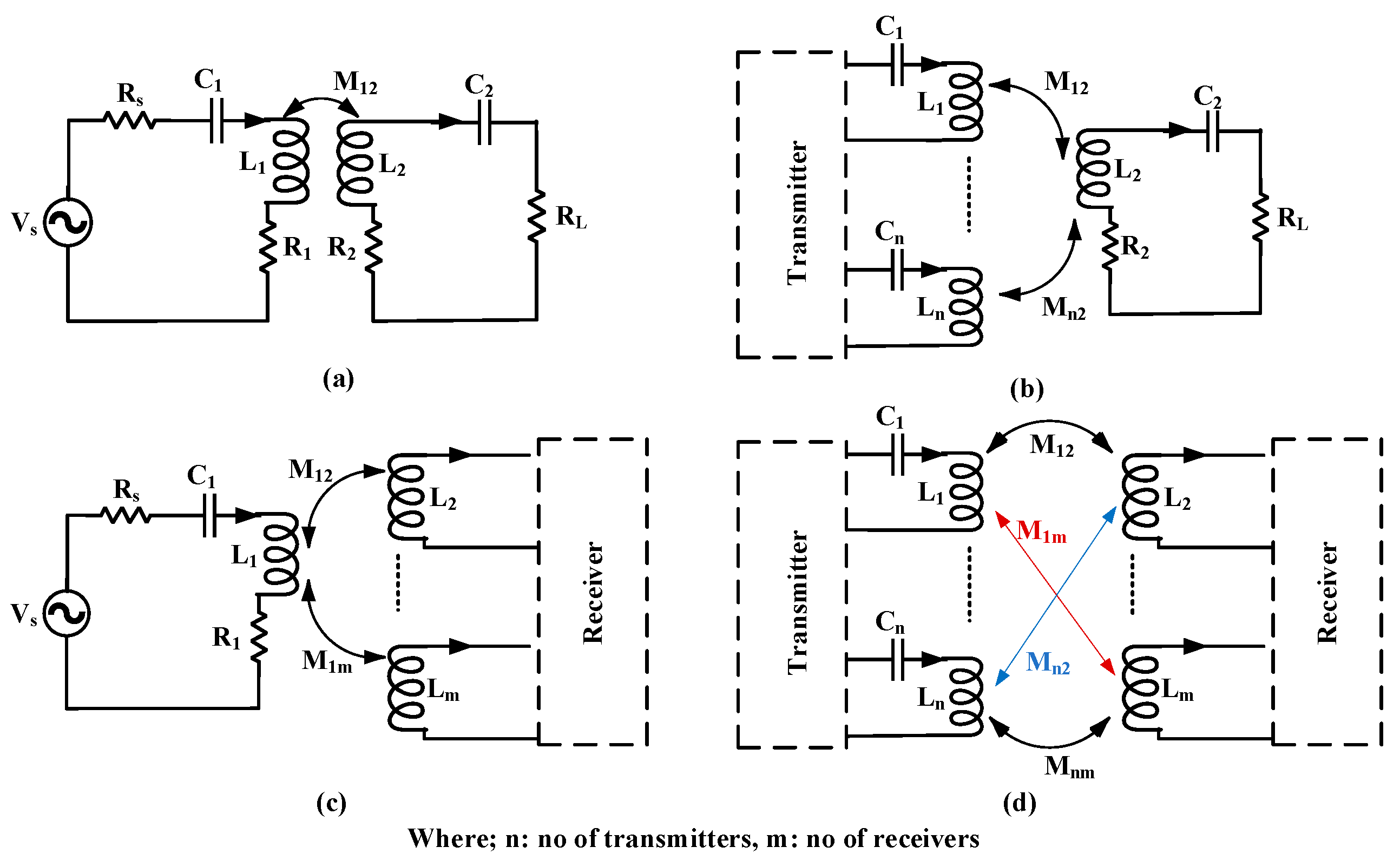
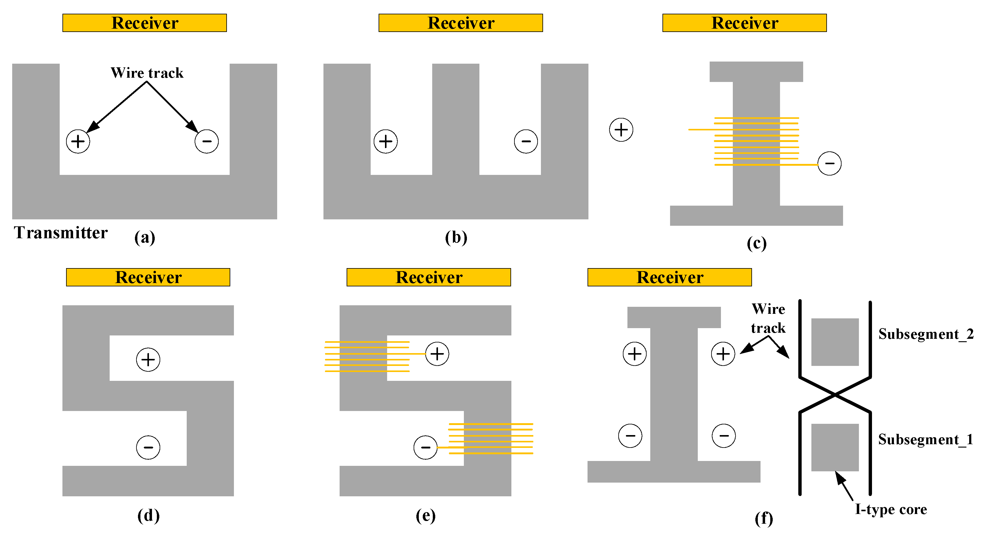
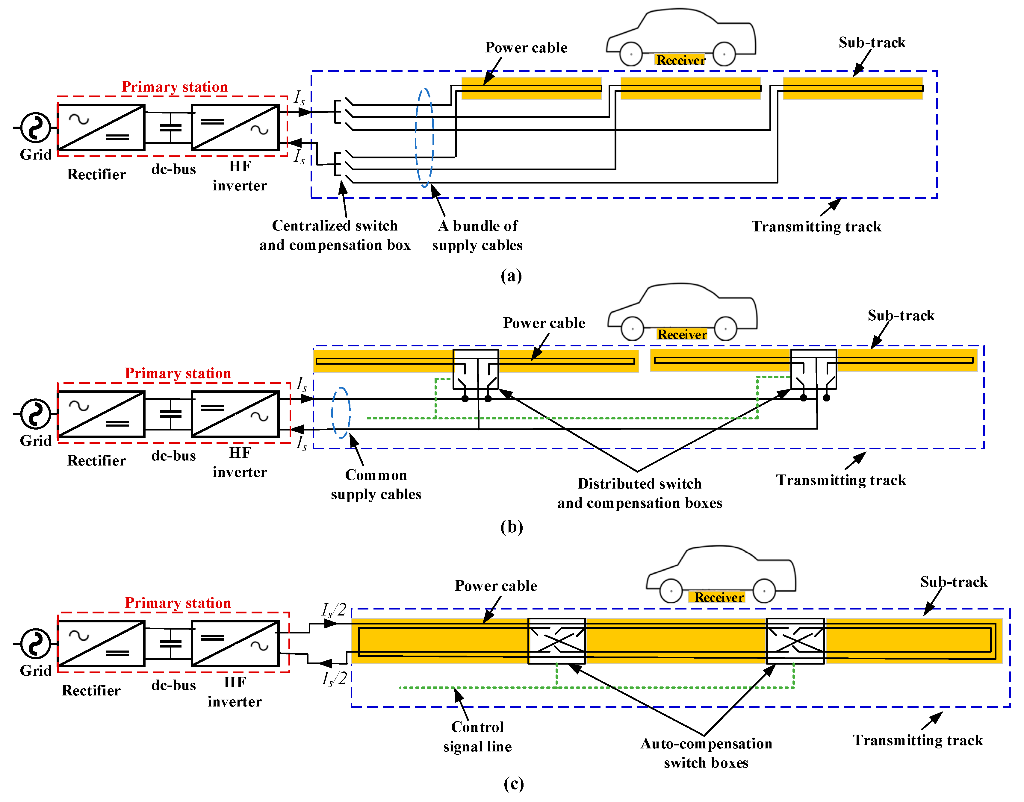
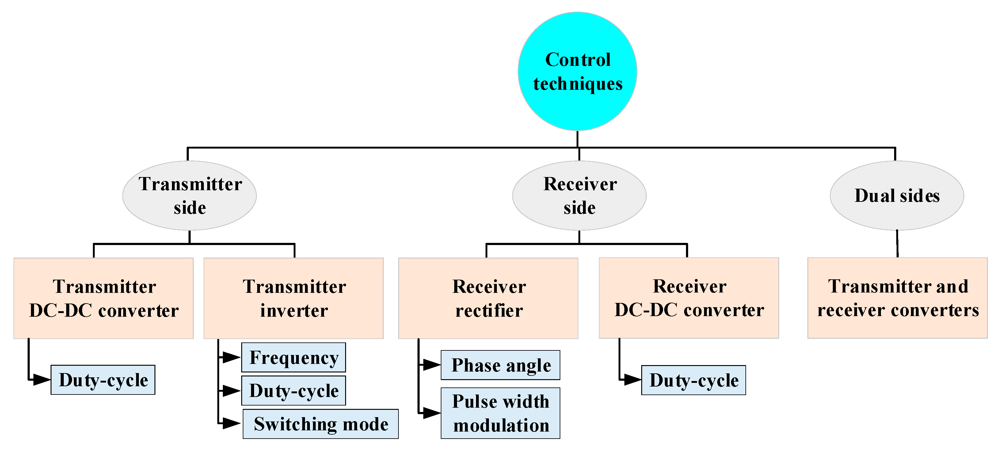
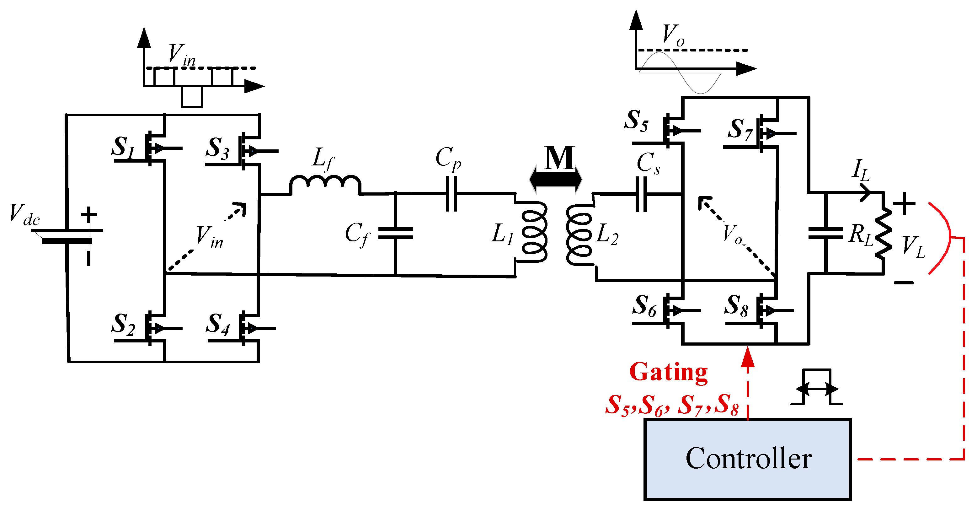
Figure 1. Simplified block diagram of an exemplary IPT system.
Energies 15 05613 g001
Figure 2. Various cases of pad implementation in DIPT system: (a) STSR, (b) MTSR, (c) STMR, and (d) MTMR.
Energies 15 05613 g002
Figure 3. Components of DIPT system with single long coil track.
Energies 15 05613 g003
Figure 4. Single transmitting wire track used in DIPT system: (a) U-type, (b) E-type, (c) I-type, (d) S-type, (e) ultra slim S-type, and (f) cross-segmented track (X-type).
Energies 15 05613 g004
Figure 5. Types of sectionalized long transmitting track: (a) centralized switching, (b) distributed switching, and (c) crossed-segmented switching.
Energies 15 05613 g005
Figure 6. Simple configuration of segmented transmitter coil track for DIPT system.
Energies 15 05613 g006
Figure 7. Supply arrangements for segmented transmitter of DIPT system (a) using a common dc-bus and (b) using a common HF ac-bus.
Energies 15 05613 g007
Figure 8. Arrangement of reflexive segmentation.
Energies 15 05613 g008
Figure 9. Additional supply arrangements for segmented transmitter of DIPT system that allow control of individual charging segments (a) using a common HF inverter with long magnetic path and (b) using a common HF inverter with series connection of transmitter segments.
Energies 15 05613 g009
Figure 10. Schematics of (a) doubled coupled system and (b) intermediate coupler circuit (ICC).
Energies 15 05613 g010
Figure 11. Implementation of receiver pad in DIPT system: (a) single pad and (b) multiple pads.
Energies 15 05613 g011
Figure 12. Classification of compensation topologies.
Energies 15 05613 g012
Figure 13. Single-element resonant topologies: (a) transmitter series, (b) transmitter parallel, (c) receiver series, and (d) receiver parallel.
Energies 15 05613 g013
Figure 14. Basic compensation topologies: (a) series–series (SS), (b) series–parallel (SP), (c) parallel–series (PS), and (d) parallel–parallel (PP).
Energies 15 05613 g014
Figure 15. Hybrid compensation topologies: (a) LCC-LCC, (b) CCL-LC, (c) LC-LC, (d) LCL-LCCL, (e) I LCL-LCL, (f) LCC-S, (g) P-PS, (h) S-SP, (i) SP-S, (j) S-LCL, (k) CCL-S, and (l) S-CLC.
Energies 15 05613 g015
Figure 16. Categorization of converter topologies for DIPT.
Energies 15 05613 g016
Figure 17. Inverter configuration for DIPT: (a) single-phase inverter driving single coil, (b) single-phase inverter driving multiple series coils, (c) single-phase inverter driving multiple parallel coils, and (d) multi-phase inverter.
Energies 15 05613 g017
Figure 18. Types of transmitter-side converter: (a) current-fed full-bridge converter, (b) voltage-fed full-bridge converter, (c) voltage-fed half-bridge converter, (d) voltage-fed LCL converter, (e) voltage-fed class D amplifier, and (f) current-fed class E RF amplifier.
Energies 15 05613 g018
Figure 19. Types of single-phase matrix converter (MC): (a) conventional single-phase MC, (b) single-phase Z-source MC, (c) six-switch buck–boost MC, and (d) high-frequency transformer (HFT)-isolated MC.
Energies 15 05613 g019
Figure 20. Types of three-phase matrix converter (MC): (a) direct MC, (b) indirect MC, and (c) three-phase Z-source MC.
Energies 15 05613 g020
Figure 21. Types of receiver-side converter: (a) buck converter for series compensated receiver and (b) boost converter for parallel compensated receiver.
Energies 15 05613 g021
Figure 22. Various control techniques for a wireless power transfer system.
Energies 15 05613 g022
Figure 23. Transmitter-side dc-link voltage control for a WPT system.
Energies 15 05613 g023
Figure 24. Transmitter-side inverter control for a WPT system.
Energies 15 05613 g024
Figure 25. Receiver-side dc-dc converter control for a WPT system.
Energies 15 05613 g025
Figure 26. Receiver side full-bridge active rectifier control for a WPT system.
Energies 15 05613 g026
Table 1. Comparison of various WPT technologies.
TechnologyPowerDistance FrequencyReferences
InductiveWatts to a few hundred kWUp to 400 mm3 kHz–1 MHz[16,17,18,19]
Magnetic resonantWatts to a few kWA few centimeters to 2 m100 kHz–10 MHz[9,11,19]
CapacitivemWatts to a few kWA few centimetersSeveral MHz[20,21,22]
Far-fieldA few kW to MWTens of meters up to several kilometers300 MHz–300 GHz[16,23,24]
Magnetic gearTens of watts to a few kW100–150 mm150 Hz–300 Hz[12,15,19,25]
AcousticMicrowatts to tens of watts70–300 mm0.5–3 MHz[10,26,27]
Table 2. Performance comparison of different single transmitting wire track used in DIPT system.
ParametersU-TypeE-TypeI-TypeS-TypeUltra Slim S-TypeX-Track
Leakage EMFHighLowMediumSmallVery lowVery low
Air gapMediumLowLargeLargeLargeLarge
Track widthVery largeMediumSmallSmallSmallSmall
EfficiencyLowHighHighLowLowHigh
Output powerSmallSmallHighHighHighHigh
Lateral misalignmentLargeSmallLargeLargeVery largeLarge
Studies[74,75][74,75][76,77][36,74][36,75][76,77]
Table 3. Transmitter capacitor C1 and total impedance ZT for the four basic topologies [9,147,148,149].
TopologyTransmitter Capacitor (C1)Total Impedance (ZT)
SS C 1 = 1 L 1 ω 2 Z T = ( R 1 + j ( L 1 ω 1 C 1 ω ) ) + M 2 ω 2 ( R 2 + R L + j ( L 2 ω 1 C 2 ω ) )
SP C 1 = 1 ( L 1 M 2 L 2 )   ω 2 Z T = ( R 1 + j ( L 1 ω 1 C 1 ω ) ) + M 2 ω 2 ( R 2 + j L 2 ω + R L 1 + j R L C 2 ω )
PS C 1 = L 1 ( M 2   ω 2   R ) 2 + ω 2   L 1 2 Z T = 1 R 1 + j L 1 ω + M 2 ω 2 ( R 2 + R L + j ( L 2 ω 1 C 2 ω ) ) + j C 1 ω
PP C 1 = L 1 M 2 L 2 ( M 2   R   L 2 2 ) 2 + ω 2   ( L 1 M 2 L 2 ) 2 Z T = 1 1 R 1 + j L 1 ω + M 2 ω 2 ( 1 + j R L C 2 ω ) ( R L + ( R 2 + j L 2 ω ) ( 1 + R L C 2 ω ) ) + j C 1 ω
Table 4. Comparison of four basic topologies [32,119,132,149,153,156,158,161].
ParameterTopologies
SSSPPSPP
Total impedanceReduces with misalignment.Reduces with misalignment.Increases with misalignment.Increases with misalignment.
Sensitivity of misalignmentLowSlightly higher than SS.HighHigh
Total copper mass at 200 kWLess copper mass than others.4.6% more than SS.30% more than SS.24% more than SS.
Independence on coupling factor and load impedanceTransmitterYesYesNoNo
ReceiverYesNoYesNo
Zero coupling allowanceNot allowedAllowedAllowedAllowed
EfficiencyVery highLowLowHigh
Output powerHighHighLowLow
Load independent outputVoltage and currentVoltage and currentOnly voltageOnly current
Proposed power levelPreferred for high power level.Low or medium power level.High power level.High power level.
Inverter device voltage ratingLower dc link voltage is required (higher than SP).Lower dc link voltage.Higher voltage is needed compared to SS and SP.Higher voltage is needed compared to SS and SP.
Inverter device current ratingTransmitter coil current.Transmitter coil current.Active component of the transmitter coil current.Active component of the transmitter coil current.
Other features
  • Load-independent output current.
  • Higher power and efficiency than SP at a frequency greater than 1 MHz.
  • Smaller receiver self-inductance than SS.
  • A stable current due to parallel compensation in receiver.
High efficiency and PF at relatively low mutual inductance and a relatively large range of load variation.Used for high-power current source driven cables that run over a long distance.
Other drawbacks
  • Load dependent on the voltage ratio transmitted at partial load conditions.
  • Requires secondary self-inductance greater than SP.
  • A higher capacitor voltage due to high frequency current.
Lacks dc component blocking.
  • Requires a current input source to avoid any instantaneous changes in voltage.
  • Large input resistance requires a high driving voltage to transfer a sufficient amount of power.
  • Low PF.
  • Large current source requirements and high load voltage of the parallel primary.
Proposed applicationWPT system (static and dynamic charging) for electric cars.
  • In biomedical applications.
  • Low-power applications.
High-power applications, electric vehicles, and buses. High-power applications, electric vehicles, and buses.
Table 5. Comparison of hybrid topologies [128,131,149,163,168,175,176,180,181].
ParameterTopologies
LCL and Its ModificationsLCC and Its ModificationsSP-SS-SP
Cost and sizeHigh Less size and cost than LCL topology.Not highNot high
Additional element on the sideTwo inductances.One capacitor, one inductance.One capacitor.One capacitor.
Features
  • Reduces the VA rating.
  • High efficiency at low quality factor.
  • Lower losses in the rectifier pickup winding.
  • Maintains high efficiency during the full range of coupling and loading.
  • Can zero current switching and zero phase angle operation at the same time.
  • Load and coupling factor independent.
  • Reduces the current stress in the inverter.
  • Compensates reactive power on the receiver side.
  • High misalignment tolerance.
  • Achieves voltage stability and blocks the dc component of the input voltage by a series-connected capacitor.
  • Constant output power for high misalignment.
  • Gives good output stability and lower circulating losses.
  • The output voltage gain is not sensitive to the parameter change around the gain intersection point.
DrawbacksThe impedance transferred to the transmitter contains both imaginary and real parts of the load.More complex in control.Large voltage on the capacitor due to high-frequency current during series compensation.Not detected.
Proposed applicationCharger of wireless power transfer for electric vehicles.
  • Charger of wireless power transfer for electric vehicles.
  • High frequency application.
Mobile system battery charge.High-power application.
Table 6. Different WPT systems based on compensation topology.
Topologyf (kHz)Po (kW)kηAir Gap (mm)CouplerStudies
SS and LCC-LCC8510.13595% for SS
93% for LCC
200Core: Circular–Circular[182]
797.70.188–0.31196% for LCC200Core: DD–DD[171,183]
SS and LCL-LCL853.30.193.1% for SS
89.5% for LCL
100Coreless: Rectangle–Rectangle[131]
LCC-LCC797.70.18–0.3296%200Core: Rectangle–Rectangle[165]
955.60.14–0.395.36%150Core: DD–DD[184]
853.30.15392.6%150Coreless: Circular–Circular[125]
8530.187795.5%150Core: DD–DD[163]
851.40.1389.78%150Core: Rectangle–Rectangle[69]
LCL-S and LCC-S14010.18–0.3293% similar LCC 100Core: Circular–Circular[99]
LCL8550.37–0.54-240Core: DD–DDCore: Bipolar–Bipolar[185]
SP232-92%100Core: Circular–Circular[186]
SS85200.480%100Coreless: Rectangle–Rectangle[187]
85--97.6%200Core: Rectangle–Rectangle[188]
Table 7. Conversion stages for DIPT with associated topologies and control handles.
Converter Stage Transmitter RectifierInverter Receiver RectifierBack-End Converter
TopologiesRectifier/ PFC.
-
Single-phase
-
Multi-phase.
-
Class EF.
-
Full-bridge diode rectifier.
-
Full-bridge synchronous rectifier.
-
Buck converter.
-
Boost converter.
-
Buck–boost converter.
Control handlesDuty ratio of PFC.
-
Duty ratio of switches.
-
Phase-shift among half-bridge.
-
Switching frequency.
No controls.Duty ratio.
Studies[101,191,192] [193,194,195][191,192][196,197]
Table 8. Inverter topologies with control contribution and complexity.
TopologySingle-phase inverter, driving single coil
-
Voltage-source full-bridge.
-
Current-source push–pull.
Single-phase full-bridge inverter, driving multiple coils
-
Parallel coils.
-
Series coils.
Multi-phase bridge inverter, driving multiple coils
System complexitySimple in implementation, but demands a lot of devices and communication between inverters.It has a smaller number of inverter and device than the single coil drive arrangement, but the control complexity is high.It is more complex for realizing soft-switch, but the device count and communication do not rely on them too much.
Segmentation controlsOpen or closed loops segmentation control is used to make the detection.
-
When segmentation control is automatic, parallel compensation is used with coils.
-
Open or closed-loop detection system is required with other structures.
According to the position of the coil, the phase switching occurs.
Studies[97,193,203] [80,98,204,205][101,197,200,206]
Table 9. Various types of single-phase MC topologies.
Single-Phase MC TopologiesConventionalZ-SourceSix-Switch Buck–BoostHFT-Isolated
Semiconductor devices4 bi-directional switches.5 bi-directional switches.6 unidirectional current flowing bi-directional voltage blocking switches.6 active switches.
Energy storage elementsNone.Two capacitors and two inductors.One inductor.
-
One dc blocking capacitor.
-
One level shift capacitor.
-
One HFT.
Merits
-
Rectification and conversion.
-
Step-up frequency.
-
Step-down voltage.
-
Buck–boost ability.
-
Step-changed frequency.
-
Safe commutation strategy required.
-
Buck–boost ability.
-
Step changed frequency.
-
No commutation problem.
-
Fast MOSFETs can be used.
-
Electrical isolation.
-
Step-changed frequency.
-
Various type of output.
-
Voltages (in or out-phase, rectified).
-
Step-changed output voltage.
Challenges
-
Limited voltage.
-
Conversion ratio.
-
Commutation problem.
-
Stored energy component.
-
Increased size.
-
Cost and losses.
Stored energy component losses.
-
Commutation problem.
-
Only buck operation.
-
Magnetic component losses.
Studies[215][216][221][222]
Table 10. Various types of single-phase MC topologies.
Three-Phase MC TopologiesDirectSparseVery SparseUltra-SparseZ-Source
Semiconductor devices9 bi-directional switches.15 IGBTs and three diodes.12 IGBTs and 18 diodes.9 IGBTs and 9 diodes.21 IGBTs.
Energy storage elementsNone.None.None.None.3 inductors and 3 capacitors.
Merits
-
High voltage transfer ratio (86%).
-
Changeable frequency.
-
Unity power factor.
-
Lesser number of IGBTs.
-
Changeable frequency.
-
High voltage transfer ratio (86%).
-
Unity power factor.
-
Lesser number of IGBTs and diodes.
-
Lower switching and conduction losses.
-
Buck–boost ability.
-
Changeable frequency.
Challenges
-
Limited voltage.
-
Commutation problem.
-
Design of input filter.
-
Conversion ratio.
-
Commutation problem.
High conduction loss.Unidirectional power flow.Higher size cost and losses.
Studies[223,230] [225,231][226,232][227,228,233][218,229]
Table 11. Various transmitter-side control techniques.
Controlled ComponentControlled ParameterKind of ControlApplicationsStudies
ConverterInverter frequency and dc-dc converter duty cycleCC and CVStationary charging[247]
InverterInverter frequency and duty cycleMaximum efficiency CCStationary charging[253]
InverterInverter frequency and duty cycleMaximum efficiencyStationary charging[193]
InverterInverter phase-shiftMaximum efficiencyStationary charging[248]
InverterInverter phase-shiftCPStationary charging[249]
InverterInverter duty cycleCVStationary and dynamic charging[250]
InverterInverter frequencyCP with ZPAStationary and dynamic charging[252]
Table 12. Various receiver-side control techniques.
Controlled ComponentControlled ParameterKind of ControlApplicationsStudies
Receiver dc-dc converterDuty cycleMaximum power transferStatic[258]
Receiver rectifierPhase controller angle (α)
and conduction angle (β)
CVStatic[261]
Receiver rectifierPulse density modulation (PDM)CV with soft switchingStatic[262]
Receiver dc-dc converterDuty cycleMaximum efficiencyDynamic[255]
Receiver rectifierPulse density modulation (PDM)CV with ZVS and ZCSDynamic[263]
ZCS: Zero current switching.
Table 13. Various dual-side control techniques.
Controlled ComponentControlled ParameterKind of ControlApplicationsStudies
Transmitter inverter and receiver rectifierTransmitter and receiver pulse width CC-CVStatic[105]
Transmitter inverter and receiver charging protection circuitTransmitter inverter phase-shift
and receiver hysteresis control
CC-CVStatic[264]
Transmitter and receiver dc-dc convertersTransmitter voltage, charging voltage, and efficiencyMaximum efficiencyStatic[145]
Transmitter and receiver dc-dc convertersTransmitter voltage, charging voltage, and efficiencyMaximum efficiencyStatic[265]
Transmitter and receiver dc-dc convertersTransmitter voltage, charging voltage, and efficiencyMaximum efficiencyStatic[266]
Transmitter inverter and receiver rectifierTransmitter voltage, charging voltage, and efficiencyMaximum efficiencyStatic[271]
Transmitter PFC, transmitter inverter, and receiver rectifierPFC duty cycle, inverter mode switching, rectifier duty cycle, and phase angleMaximum efficiencyStatic[114]
Transmitter inverter and receiver rectifierEfficiencyMaximum efficiency CC/CV with ZVSStatic[272]
Table 14. Comparison between merits and demerits of each control technique.
Control Type ConverterMeritsDemerits
Transmitter-sidedc-dc converter
-
The operating frequencies varies with the inductive link.
-
The grid rectifier efficiency increased when operating as PFC.
-
Communications are required in control in case of misalignment.
-
Maximum efficiency strategies cannot be implemented.
Inverter
-
Easy to control the output voltage.
-
The dc-dc converter is not required.
-
Possibility to set the frequency to enhance the resonance.
-
Communications are required in control in case of misalignment.
-
Maximum efficiency strategies cannot be implemented.
Receiver-sidedc-dc converter
-
Communications are not required in petty control techniques, even in case of misalignment.
-
Operating frequency is different from inductive link.
The inability to control charging power and efficiency at the same time.
Controlled rectifier
-
Communications are not required in petty control techniques, even in case of misalignment.
-
The dc-dc converter is not required.
Synchronization between the ac signal and the controller is required.
Dual-side-
-
Improved maximum efficiency techniques can be provided.
-
Charging power is almost constant under misalignments without exceeding component limits.
In most strategies communications are needed.
Table 15. Summary of R&D for DIPT system.
ParameterPower (kW)FrequencyAir GapEfficiencyTransmitterReceiverMisalignmentStudies
KAISTG1320 kHz10 mm88%E-typeE-type~3 mm[74,283]
G2620 kHz170 mm72%U-typeFlat-type~230 mm[74,75]
G31560 kHz120 mm80%W-typeDD coil[74]
G427200 mm74%I-typeDD coil240 mm[36,68]
G522200 mm71%S-typeDD coil300 mm[36,74]
G63.385 kHz100–300 mm83%W-type with ferrite plateRectangular700 mm[278]
ORNL1.523 kHz100 mm75%Circular with ferrite barsCircular with ferrite bars[186]
2022 kHz162 mm93%Rectangular with ferrite coreRectangular with ferrite bars150 mm[284]
UoA20–3012.9 kHz50 mm85%50 mm[18,32,285]
USU2520 kHz86%Circular with ferrite barsCircular with ferrite bars150 mm[238]
CW12015–20 kHz40 mm90%E-typeF-type[32]
NRC190 kHz100 mm>90%RectangularCircular with ferrite core[286]
NCSU0.3100 kHz170 mm77–90%CircularCircular with ferrite plate~30 mm[79,287]
WAVE5020 kHz152–254 mm90%~254 mm[32,288]
JRTRI5010 kHz7.5 mmBipolarDD coil[289]
Bombardier20020 kHz60 mm90%A few mm[32,290]
FDIAU8020 kHz100 mm88–90%[19]
PATH60 76 mm60%[273]
RNL = Oak Ridge National Laboratory, UoA = University of Auckland, USU = Utah State University, CW = Conductix-Wampfler, NRC = Nissan Research Centre, NCSU = North Carolina State University, JRTRI = Japan Railway Technical Research Institute, FDIAU = Flanders Drive with industries and universities.
Table 16. Summary for the different standards of EV inductive stationary charging.
DeveloperNameDescriptionStatusDateReferences
SAEJ2954Introduces guidelines which determine acceptable criteria for interoperability principle, EMFs compatibility, minimum performance, safety degree, and testing for wireless charging of light duty and plug-in EVs. This version considers unidirectional charging operation, from grid to vehicle (G2V).Published2020[31,291]
J1773Defines the minimum accepted limits of interface requirements for EVs, in addition to inductive charging in areas of the same geographical nature. It is recommended to transmit power at higher frequencies than power line frequencies.Stabilized2014[292]
J2847/6_202009Defines the accepted limits for communication between an EV and an inductive battery charging system for WPT.Revised2020[293]
J2836/6_201305Defines the communication cases that are used for EVs and the wireless EV supply equipment (EVSE) for wireless power transmission as defined in SAE J2954. It provides the communication requirements between the on-board charging system and wireless EVSE to support WEVSE detection, charging operation, and charging operation monitoring.Revised2021[294]
IECIEC 61980-1Universal requirements. It introduces recommendations that apply to equipment to transmit power wirelessly using the inductive charging concept, to supply power to storage devices such as insulating batteries or to supply the power to the grid when needed. The areas presented in this issue are the characteristics for the desired safety limit of a supply device, communications between the EV and transmitter device to enable and control the WPT system, and specific EMFs compatibility requirements for a supply device.Active, most current2020[295,296]
IEC/TS 61980-2Presents particular conditions for communication between EVs and infrastructure in order to facilitate the charging in a WPT system. Work has also been done to reach the communication requirements for charging vehicles with two and three wheels, and communication requirements during bidirectional charging. This release does not address safety requirements during maintenance or for trolley buses and trucks designed for off-road use.Active, most current2019[297]
IEC/TS 61980-3Specifies special requirements for the magnetic field wireless power transfer (MF-WPT) generated in the wireless charging system. Work has also been done to reach the communications requirements for required safety by a MF-WPT system, the requirements to assure efficient and safe MF-WPT power transfer, and specific EMFs compatibility requirements for MF-WPT systems.Active, most current2019[298]
JARIG106:2000Provides the general requirements to provide inductive charging for EVs.Published2000[299]
G108:2001Provides the software interface for the inductive charging system of EVs.2021
G109:2001Describes the use of the IPT system to transfer power wirelessly. It also defines universal requirements for the wireless charging process.2001[291,300]
ULUL9741Provides universal requirements for the interchange charging operation considering the bidirectional charging process to supply the power to the grid and feed traditional loads.Active2017[9,301]
UL-SUBJECT 9741Defines the requirements for each unidirectional and bidirectional operation for electric vehicles. Unidirectional operation supplies power from the utility grid to charge the electric vehicle battery. Bidirectional operation serves the same function but additionally provides power to the utility grid from the electric vehicle.Active2021[302]
Publisher’s Note: MDPI stays neutral with regard to jurisdictional claims in published maps and institutional affiliations.

