1. Introduction
An electro-mechanical transmission belongs to a transmission form of power-split hybrid electric vehicles. It has two power transmission paths, i.e., electric power and mechanical power, which can not only realize the efficient operation of the engine, but also make full use of the advantages of the mechanical power path, so it can greatly improve the fuel economy and power performance of the vehicle. For heavy vehicles such as engineering vehicles, due to the complexity of operating conditions and the need for an external power output, such as loader shovel dug devices, it is not realistic to use the battery electric vehicle at the present stage. Therefore, an electro-mechanical transmission is the optimum transmission form of heavy vehicles.
Due to the limitation of the motor power and speed regulation range, a single-mode hybrid electric transmission scheme cannot meet the power demand of heavy vehicles. The research of multi-mode electro-mechanical transmissions is mostly the theoretical research of transmission characteristics [
1,
2,
3,
4,
5] and control strategies [
6,
7,
8,
9,
10,
11,
12]. Zou et al. [
13] studied the modeling and fuel management of a powertrain split on HEVs. Furthermore, there is more research on the characteristics of multi-mode electro-mechanical compound transmissions [
14]. Du et al. [
15] proposed the idea of modularization to solve the graph theory expression of the computer recognition configuration, and the reverse search algorithm and forward backtrack algorithm were used to solve the problem of the configuration dynamic parameter calculation. Based on the analysis of the characteristics of multi-mode electro-mechanical compound transmissions, several methods of multi-mode compound transmission schemes have been proposed [
16,
17,
18,
19,
20,
21]. Gao et al. [
22] proposed a new graph theory expression method which can simplify the dynamic and static analysis. Based on this graph theory expression method, the configuration synthesis method of an electric drive tracked vehicle was proposed. Ho et al. [
23,
24] constructed an atlas of generalized kinematic chains according to the topological characteristics of existing hybrid transmissions and obtained feasible kinematic chains by applying the specified design requirements and constraints, and then designed working modes based on the lever analogy to obtain the atlas of multi-mode hybrid transmission. Liu et al. [
25], based on the lever analogy method, designed a dual-mode powertrain by adding PG and the DOF of configuration based on the compound split mode, and designed three-mode powertrains by adding an input split or compound split mode on the basis of the dual-mode powertrain. Most of the above research is carried out for configuration generation, characteristic analysis and parameter optimization, rather than the forward design of multi-mode electro-mechanical transmission schemes from the perspective of mode jointing characteristics.
In this paper, by analyzing the distribution of mechanical points and the speed continuous condition of mode switching, the combination law of dual-mode electro-mechanical transmission is obtained. Based on the combination law, a scheme design method of the dual-mode electro-mechanical transmission is proposed. Through a computer aided design, the transmission scheme can be generated and screened quickly.
2. Mechanical and Electrical Hybrid Transmission Scheme Graph Theory
2.1. Planetary Mechanism
Based on the layered thought, the planetary-gear is divided into ring gear, carrier and sun gear. The single planetary-gear can be expressed as the lever model shown in
Figure 1.
For the multiple planetary-gear mechanism, each planetary-gear has 2-DOF. For each additional internal connection between the components of different planetary-gears, the mechanism will reduce one DOF. The freedom can be calculated as:
where
F represents the freedom,
P represents the planetary-gear, and
C represents the fixed number of connections.
According to scheme (1), the two planetary-gear can be divided into 2-DOF (two fixed connections) and 3-DOF (a fixed connection).
As shown in
Figure 2a, according to the Lever Analogy Method, a compound lever model can be established by two DOFs mechanisms and the compound level model is a four nodes lever. The 3-DOF mechanism cannot be compounded into a lever, represented by the
Figure 2b model.
2.2. External Force Components
For the 2-DOF planetary set, external force components include one engine, two motors, and one output shaft. According to the connection of external force components, an electro-mechanical transmission can be divided into the input split, compound split and output split. As shown in
Figure 3, rectangles MA, IN, OUT and MB represent motors A, engine, output, and motors B, respectively.
For 3-DOF mechanism, the external force component brake also needs to be added. The difference with the 2-DOF scheme is that the brake limits the rotation speed of a component of one planetary-gear to zero. The relationship between the other two components of the planetary-gear can be simplified to a fixed transmission ratio. At this point, the 3-DOF transmission mechanism can be simplified into the lever model shown in
Figure 4.
The simplified lever model is the three nodes lever, which is essentially a single planetary-gear. As the compound split speed transmission requires four nodes for positioning power components, the 3-DOF transmission scheme has only two transmission forms: the output split 3-DOF transmission scheme (
Figure 4a) and the input split (
Figure 4b) two transmission scheme.
3. Mode Combination Law
3.1. Mechanical Point Distribution of Single-Mode Scheme
When the speed of the motor is zero, the ratio of the output speed to input speed is defined as the mechanical point. The values of mechanical points can be divided into: (1) (−∞, 0); (2) 0; (3) (0, 1); (4) (1, +∞). For the 2-DOF scheme: The scheme of the input split and compound split have two mechanical points, with a total of
distributions, as shown in
Table 1 (scheme type 1 to scheme type 9). The scheme of output split has only one mechanical point and has three distributions, as shown in
Table 1 (scheme type 10 to scheme type 12). The 3-DOF scheme is derived from the 2-DOF scheme, and the distribution of the mechanical points can be obtained by adjusting the corresponding scheme type in
Table 1.
In order to fully utilize the motor performance of the multi-mode scheme, mode switching should be carried out at the mechanical points. If the mechanical point is located on the negative half axis, the travel interval between the two mechanical points is negative, so the efficiency of the motor is wasted, and then scheme types 3, 7, 8, 9 and 10 can be eliminated. If both mechanical points are distributed in the (0, 1) or (1, +∞) interval, the speed range is too narrow to match the motor, so scheme types 3, 5, 6, 8 and 9 can be eliminated.
Therefore, the speed regulation ranges of scheme types 1, 2 and 4 are ideal and can be used as the preferred scheme. One mechanical point of scheme types 1 and 2 is 0, that is, the output speed starts from 0, which should be used as the first mode. In scheme 4, both mechanical points are greater than 0, which should be used as the second mode.
3.2. The Conditions of Speed Continuity
In order to ensure the smoothness and continuity of mode switching, the mode combination should ensure the continuity of the speed of each power component and meet the following conditions: (1) the adjacent mechanical points of two adjacent modes are equal and (2) the two motors at the mechanical point have the same speed, expressed by the formula:
where
nA1,
nA2,
nB1 and
nB2 represent the speed of motor A first mode, motor A second mode, motor B first mode and motor B second mode.
MPA1 and
MPA2 represent the positions of the mechanical point of motor A and motor B.
3.3. Mode Jointing Law Analysis
The scheme type 1 and type 4 combinations are shown in
Table 2. The mechanical point of the 2-DOF scheme of scheme type 1 for mode jointing is behind
ni. In scheme type 2, the mechanical point used for mode jointing is
ni, which does not meet the continuous speed condition, so mode jointing cannot be carried out. In the 3-DOF scheme of scheme type 1, there is a fixed transmission ratio k between the output shaft and the planetary-gear components, which can change the position of the mechanical point, meet the conditions of continuous speed, and carry out mode jointing.
The combination of the scheme types 2 and 4 are shown in
Table 3. Although the 2-DOF scheme of type 2 and scheme type 4 are in the same interval, the speed of motor B at the mechanical point is one less than
ni and one is greater than
ni, which does not meet the continuous speed condition, meaning that mode jointing cannot be carried out. In the 3-DOF scheme of type 2, there is a fixed transmission ratio
k between motor B and the planetary-gear components which can change the speed slope of motor B, as shown in the
Table 2. If the speed continuous condition is met, the mode jointing can be carried out.
According to the above analysis, the mode jointing rule can be summarized in the following ways: (1) at least one of the two modes is a 3-DOF scheme, and (2) for the two-planetary-gear electro-mechanical transmission, the first mode can only select the 3-DOF scheme of the input split, and the second mode can only select the 2-DOF scheme of compound split.
4. Dual-Mode Electro-Mechanical Transmission Scheme Generation
4.1. Single-Mode Scheme Generation
In
Table 2, the three schemes are classified according to the values of mechanical points:
- (1)
2-DOF scheme: one mechanical point between 0 and ni, another mechanical point is more than ni.
- (2)
3-DOF scheme: one mechanical point is equal to 0, and the other mechanical point is between 0 and ni.
By using this as a screening condition, the single-mode scheme of the mode combination can be obtained. The specific implementation process is shown as follows:
The speed relation formula can be obtained from the speed characteristics of the planetary-gear:
These are obtained by the connection relationship:
where the subscripts
i,
j,
k,
l, m and
n represent the components’ name or components’ label connected to the other end.
The two mechanical points obtained from Formulas (3) and (4) are:
In an engineering application, the values of key characteristic parameters and
k2 are in the range of 1.5–4, and the mechanical point value of each scheme can be determined to judge whether the scheme meets the requirements. The number of optimized single-mode schemes is calculated as shown in
Table 4.
4.2. Dual-Mode Scheme Generation
By pairing the two types of schemes in
Table 3, 144 × 92 = 13,248 cases can be obtained. The continuous speed condition for each case must be judged and then the equation group in Formula (2) can be solved. There are several cases which can solve the equation group, as follows:
- (1)
If it has no concern with k1 and k2, the equation is always true, and such schemes are reasonably matched;
- (2)
If k1 and k2 satisfy a certain relationship and the equation holds, the scheme matching is reasonable;
- (3)
If k1 and k2 take certain values and the equation holds, the scheme matching is reasonable;
- (4)
Regardless of the values of k1 and k2, the equation is not tenable and the scheme matching is unreasonable.
4.3. Scheme Optimization
- (1)
Reasonable judgment of mode switching control
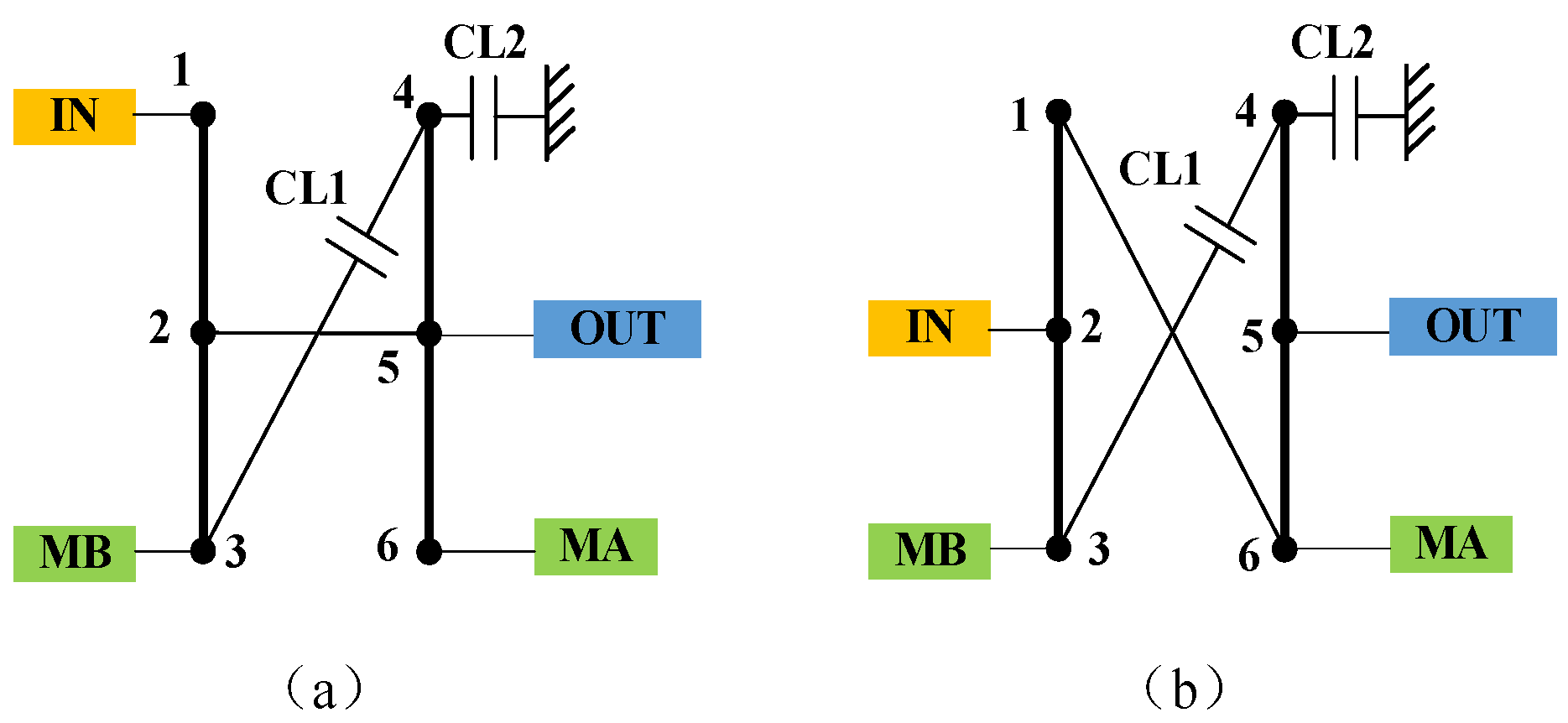
From the perspective of engineering applications, it is most reasonable to replace only one control component during mode switching so that there is only one connection between two adjacent modes. As shown in
Figure 5, the connection set of mode (a) is {{7,2},{8,6},{9,3},{10,5},{11,4},{1,6}}, and the connection set of mode (b) is {{7,2},{8,6},{9,3},{10,5},{3,4},{1,6}}. The different set operation was performed between them and the operation result is {{11,4}}. It contains only one element, so switching between the two modes (a) and (b) can ensure reasonable manipulation, as shown in
Figure 5c.
- (2)
The scheme of isomorphism judgment
The external force components are, respectively, connected to the two ends of the fixed connecting edge to form isomorphism. As shown in
Figure 6, component 8 is connected to components 1 and 6, respectively, while components 1 and 6 are fixed connections and belong to the same component as a whole. Therefore, schemes (a) and (b) are isomorphic. The connection sets of the two schemes do the different set operations on each other to get {8,6} and {8,1}, which is the second pair of connections in
Table 5, and take the union set to get {8,1,6}. This shows that the fixed connection {1,6} is a subset of the set {8,1,6} and proves that the two schemes are isomorphic.
4.4. Result of Scheme Being Optimized
After the above optimization, the dual-mode scheme is obtained, as shown in
Figure 7. Among them, scheme (a) has been applied to the dual-mode of the General Motors Company system.
5. Characteristic Analysis of Optimized Transmission Scheme
Kinematic and dynamic characteristics of the optimized scheme are analyzed to verify the rationality of the scheme. Assuming that the electric power is balanced and the power loss is zero, the engine and the input power output to the transmission mechanism meet the following formula:
where
Pin represents engine power,
Pout represents the power output to the transmission mechanism.
The speed ratio
is can be defined:
where
Tin and
Tout represent Engine input torque and the torque output to the transmission mechanism.
5.1. Speed Characteristic Analysis
Taking scheme (b) in
Figure 7 as an example, the speed characteristics of the planetary-gear can be obtained:
According to the connection, the first mode can be written as:
The second mode can be calculated as:
From Formulas (7)–(10), the relative speed expressions of two mode motors A and B can be solved, respectively, as shown:
According to Formulas (11) and (12), the relative speed curves of motors A and B in the full output range can be obtained. Similarly, the speed characteristics of another scheme can be obtained. The speed characteristics of the two preferred schemes are shown in
Figure 8.
5.2. Analysis of Torque Characteristics
From the torque characteristics of the planetary-gear itself:
Obtained by the connection relationship:
The first mode can be expressed as:
The second mode can be expressed as:
Then the relative torques of motors A and B in the two modes can be obtained from Formulas (7) and (13)–(15), respectively:
where
T1,
T2,
T3,
T4,
T5,
T6,
TA,
TB,
Tin and
Tout represent the torque of components 1, 2, 3, 4, 5, 6 and the torque of Motor A, Motor B, the engine and the output, respectively.
k1 and
k2 represent the planetary-gear characteristic parameters.
According to Formulas (16) and (17), the relative torque curves of motors A and B in the full output range can be obtained. Similarly, the torque characteristics of another scheme can be obtained, as shown in
Figure 9. Through mode combination, the demand for motor torque can be reduced, so a smaller motor can be selected. When the speed ratio is small, the relative torque of motor B is large because the engine torque is small and the torque of the motor is actually very small.
5.3. Analysis of Power Split Characteristics
The ratio of the electrical power to the mechanical power is called the power split ratio. The larger the power split ratio, the less power is directly output through the transmission mechanism, and the lower the efficiency of the transmission system. Therefore, the power split ratio can be used to characterize the transmission efficiency of the transmission system. The power split ratio can be represented as:
According to the expressions of speed and torque in
Section 4.1,
Section 4.2 and Formula (18), the power split ratio curves of motors A and B can be obtained. As shown in
Figure 10, the power split ratio curves of the two schemes have the same trend. Within the full output range, the power split ratio of the two motors always maintains one positive and the other negative. Moreover, one motor acts as a motor and the other motor acts as a generator to ensure the balance of electric power. The working range of the two modes is the interval with a low split ratio [
2], so the overall efficiency is improved compared with the single-mode scheme, which proves that the optimization of the dual-mode scheme is reasonable and feasible.
6. Conclusions
In the first and second parts, the single-mode electro-mechanical transmission scheme is analyzed through the distribution of mechanical points. Taking the continuous speed as the condition for the mode connection, the mode jointing scheme of two-mode electro-mechanical transmission is obtained, that is the 3-DOF input split scheme and the 2-DOF compound split scheme. At least one of the two modes is a 3-DOF scheme.
The third part proposes a two-mode electro-mechanical transmission scheme design method based on articulation characteristics, which is combined from a single-mode scheme into a dual-mode scheme. The scheme is designed based on the configuration of two planetary row mechanisms and, after screening, two optimal schemes are obtained. After the above optimization, a dual-mode scheme is obtained, one of which has been applied to the dual-mode system of General Motors.
The fourth part analyzes the speed, torque and power split characteristics of the optimized scheme, respectively. The results show that the optimized scheme is reasonable and feasible, and the accuracy of the proposed design method is proved.
Author Contributions
Conceptualization, X.L. and S.Y.; methodology, X.L.; software, X.K.; validation, X.L., X.B. and Z.P.; formal analysis, X.K.; data curation, Z.Z.; writing—original draft preparation, X.B.; writing—review and editing, Z.Z.; supervision, S.Y.; project administration, Z.P.; funding acquisition, X.L. All authors have read and agreed to the published version of the manuscript.
Funding
This research was funded by the National Natural Science Foundation of China, grant number 52102429.
Institutional Review Board Statement
Not applicable.
Informed Consent Statement
Informed consent was obtained from all subjects involved in the study.
Data Availability Statement
Not applicable.
Conflicts of Interest
The authors declare no conflict of interest.
References
- Wu, X.; Fu, J.; Sun, Z. Research on Parameter Matching of Powertrain of Single Axis Parallel Hybrid Electric Vehicle. Automob. Appl. Technol. 2021, 22, 88–91. [Google Scholar]
- Hu, J.; He, R.; Peng, Z. An Analysis on the Characteristics of Electromechanical Transmission with Multi-planetary Gearing. Automot. Eng. 2014, 36, 1085–1092. [Google Scholar]
- Wang, W.; Song, R.; Guo, M. Analysis on compound-split configuration of power-split hybrid electric vehicle. Mech. Mach. Theory 2014, 78, 272–288. [Google Scholar] [CrossRef]
- Wróblewski, P.; Kupiec, J.; Drozdz, W.; Lewicki, W.; Jaworski, J. The Economic Aspect of Using Different Plug-In Hybrid Driving Techniques in Urban Conditions. Energies 2021, 14, 3543. [Google Scholar] [CrossRef]
- Wang, W.; Song, R.; Liu, S. An Analysis on the Configuration of Dual-mode Power-split Hybrid Powertrain System. Automot. Eng. 2015, 37, 648–654, 724. [Google Scholar]
- Zhang, F.; Hu, X.; Langari, R.; Cao, D. Energy management strategies of connected HEVs and PHEVs: Recent progress and outlook. Prog. Energy Combust. Sci. 2019, 73, 235–256. [Google Scholar] [CrossRef]
- Xiang, C.; Wu, Y.; Wang, W. Electric power coordinated control strategy of dual-mode electro-mechanical transmission system. J. Harbin Inst. Technol. 2017, 49, 120–125. [Google Scholar]
- Liu, Y.; Xiao, Y.; Yu, F. Study on Energy Management Strategy and Analysis of Power Split Hybrid Electric Vehicle. Drive Syst. Tech. 2019, 33, 3–13. [Google Scholar]
- Mounica, V.; Obulesu, Y.P. Hybrid Power Management Strategy with Fuel Cell, Battery, and Supercapacitor for Fuel Economy in Hybrid Electric Vehicle Application. Energies 2022, 15, 4185. [Google Scholar] [CrossRef]
- Kommuri, N.K.; McGordon, A.; Allen, A.; Truong, D.Q. A Novel Adaptive Equivalence Fuel Consumption Minimisation Strategy for a Hybrid Electric Two-Wheeler. Energies 2022, 15, 3192. [Google Scholar] [CrossRef]
- Donatantonio, F.; Ferrara, A.; Polverino, P.; Arsie, I.; Pianese, C. Novel Approaches for Energy Management Strategies of Hybrid Electric Vehicles and Comparison with Conventional Solutions. Energies 2022, 15, 1972. [Google Scholar] [CrossRef]
- Kommuri, N.K.; McGordon, A.; Allen, A.; Truong, D.Q. Evaluation of a Modified Equivalent Fuel-Consumption Minimization Strategy Considering Engine Start Frequency and Battery Parameters for a Plugin Hybrid Two-Wheeler. Energies 2020, 13, 3122. [Google Scholar] [CrossRef]
- Zou, Y.; Huang, R.; Wu, X.; Zhang, B.; Zhang, Q.; Wang, N.; Qin, T. Modeling and energy management strategy research of a power-split hybrid electric vehicle. Adv. Mech. Eng. 2020, 12, 12. [Google Scholar] [CrossRef]
- Pinto, S.D.; Mantriota, G. A simple model for compound split transmissions. Proc. Inst. Mech. Eng. Part D J. Automob. Eng. 2014, 228, 549–564. [Google Scholar] [CrossRef]
- Du, M.; Yang, L. A basis for the computer-aided design of the topological structure of planetary gear trains. Mech. Mach. Theory 2020, 145, 103690. [Google Scholar] [CrossRef]
- Cammalleri, M.; Castellano, A. Analysis of hybrid vehicle transmissions with any number of modes and planetary gearing: Kinematics, power flows, mechanical power losses. Mech. Mach. Theory 2021, 162, 104350. [Google Scholar] [CrossRef]
- Jiang, X.; Hu, J.; Peng, H. A Design Methodology for Hybrid Electric Vehicle Powertrain Configurations with Planetary Gear Sets. J. Mech. Des. 2021, 143, 083402. [Google Scholar] [CrossRef]
- Xu, X.; Sun, H.; Liu, Y. Automatic Enumeration of Feasible Configuration for the Dedicated Hybrid Transmission with Multi-Degree-of-Freedom and Multiplanetary Gear Set. J. Mech. Des. 2019, 141, 093301. [Google Scholar] [CrossRef]
- Zhuang, W.; Zhang, X.; Peng, H. Rapid Configuration Design of Multiple-Planetary-Gear Power-Split Hybrid Powertrain via Mode Combination. IEEE/ASME Trans. Mechatron. 2016, 21, 2924–2934. [Google Scholar] [CrossRef]
- Zhuang, W.; Zhang, X.; Zhao, D. Optimal design of three-planetary-gear power-split hybrid powertrains. Int. J. Automot. Technol. 2016, 17, 299–309. [Google Scholar] [CrossRef] [Green Version]
- Ngo, H.; Yan, H. Configuration synthesis of parallel hybrid transmissions. Mech. Mach. Theory 2016, 97, 51–71. [Google Scholar] [CrossRef]
- Gao, M.; Hu, J.; Peng, Z. Configuration synthesis of electric-drive transmissions for tracked vehicles. Adv. Mech. Eng. 2018, 10, 1687814017749665. [Google Scholar] [CrossRef]
- Ho, T.T.; Hwang, S.J. Configuration synthesis of two-mode hybrid transmission systems with nine-link mechanisms. Mech. Mach. Theory 2019, 142, 103615. [Google Scholar] [CrossRef]
- Ho, T.T.; Hwang, S.J. Configuration Synthesis of Novel Hybrid Transmission Systems Using a Combination of a Ravigneaux Gear Train and a Simple Planetary Gear Train. Energies 2020, 13, 2333. [Google Scholar] [CrossRef]
- Liu, C.; Hu, J.; Peng, Z.; Yang, S. Analysis on Three-Mode Configurations of Power-Split Hybrid Electric Vehicle. In Proceedings of the ASME International Design Engineering Technical Conferences & Computers & Information in Engineering Conference (IDETC/CIE 2015), Boston, MA, USA, 2–5 August 2015. Paper No. DETC2015-46754. [Google Scholar]
| Publisher’s Note: MDPI stays neutral with regard to jurisdictional claims in published maps and institutional affiliations. |
© 2022 by the authors. Licensee MDPI, Basel, Switzerland. This article is an open access article distributed under the terms and conditions of the Creative Commons Attribution (CC BY) license (https://creativecommons.org/licenses/by/4.0/).


