
A Numerical Study on the Performance Evaluation of a Semi-Type Floating Offshore Wind Turbine System According to the Direction of the Incoming Waves


Abstract
:1. Introduction
2. Numerical Setup
2.1. Target Model
2.2. Validation of the FAST Numerical Model
2.3. Environmental Conditions
3. Results and Discussion
3.1. Platform’s Motion and Loads
3.2. Platform’s Yaw Motion of a Large Floating Offshore Wind Turbines System
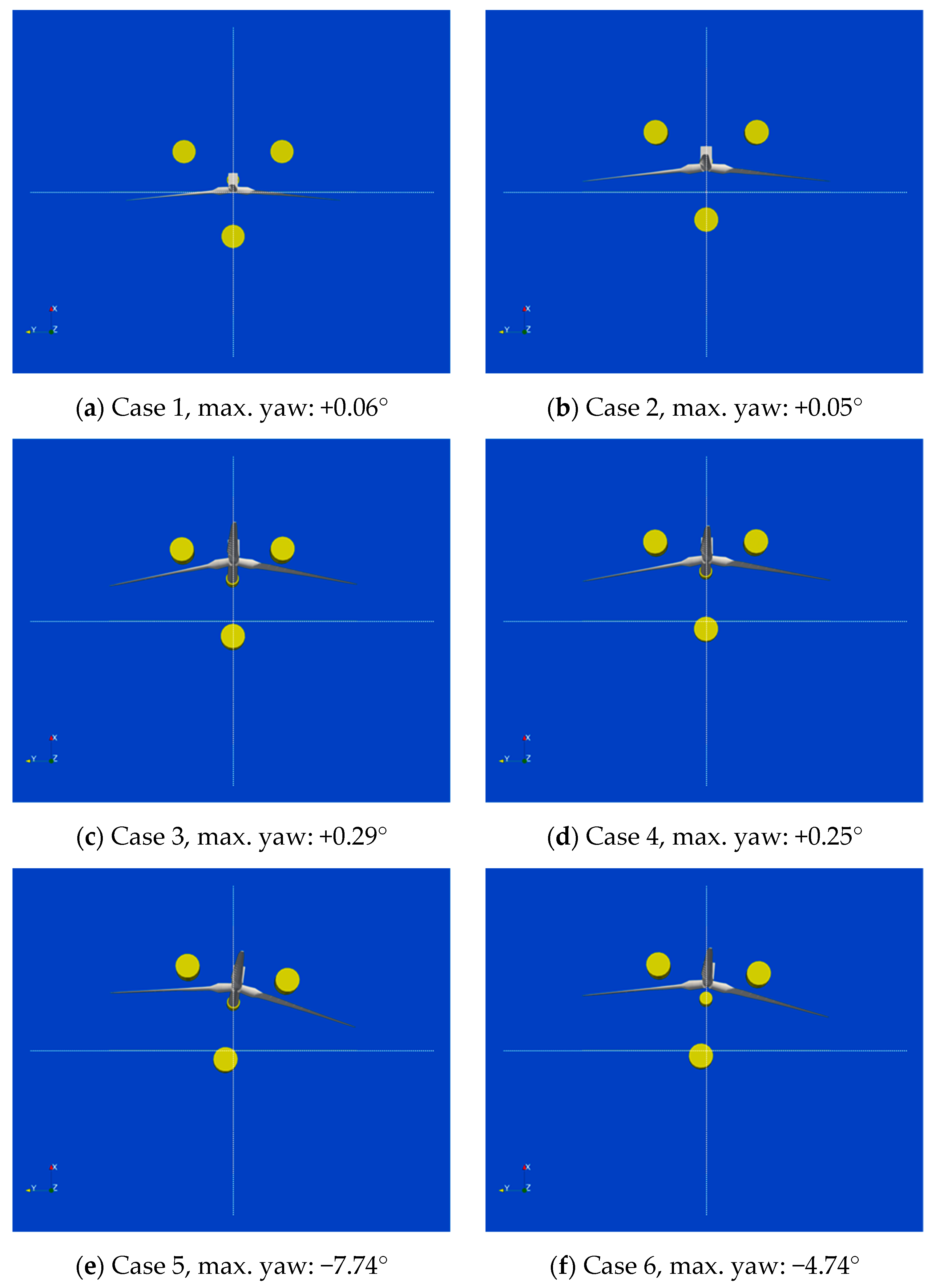
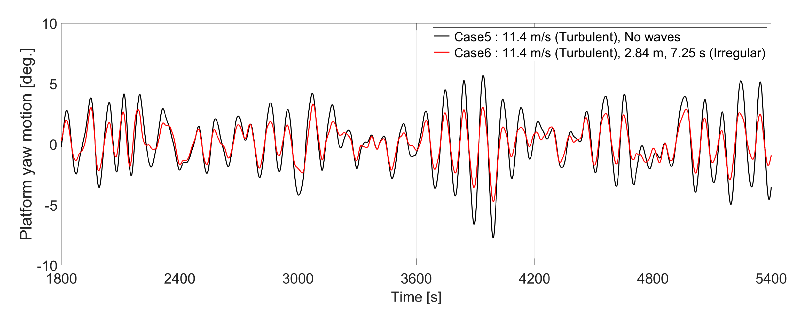
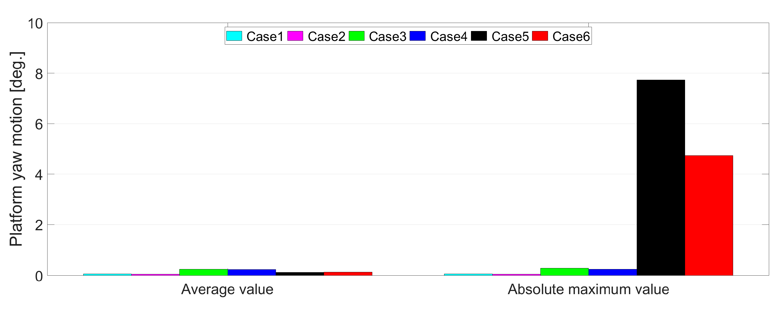
3.2.1. Causes of the Platform’s Yaw Motion
3.2.2. Influence of the Platform Yaw’s Motion
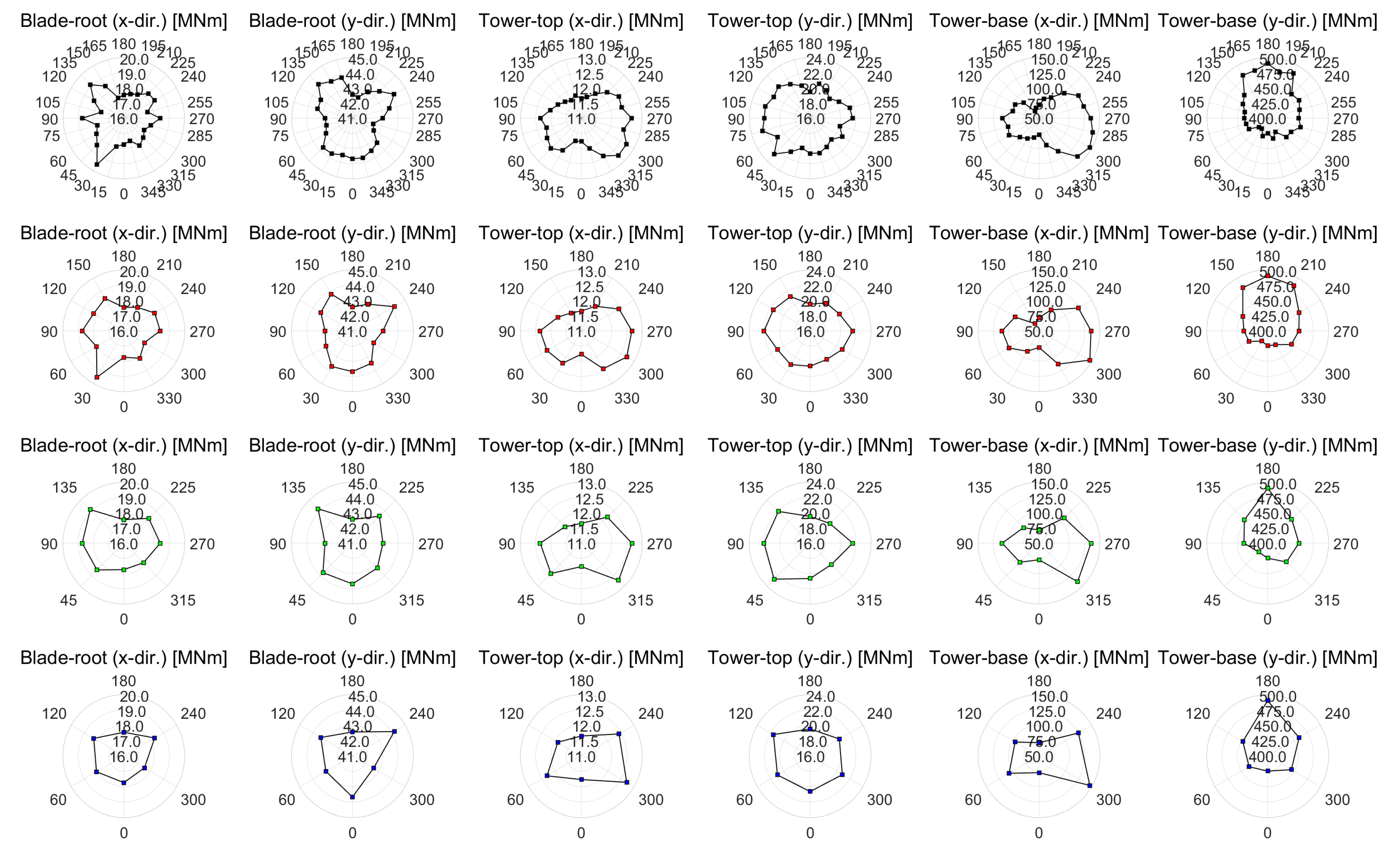
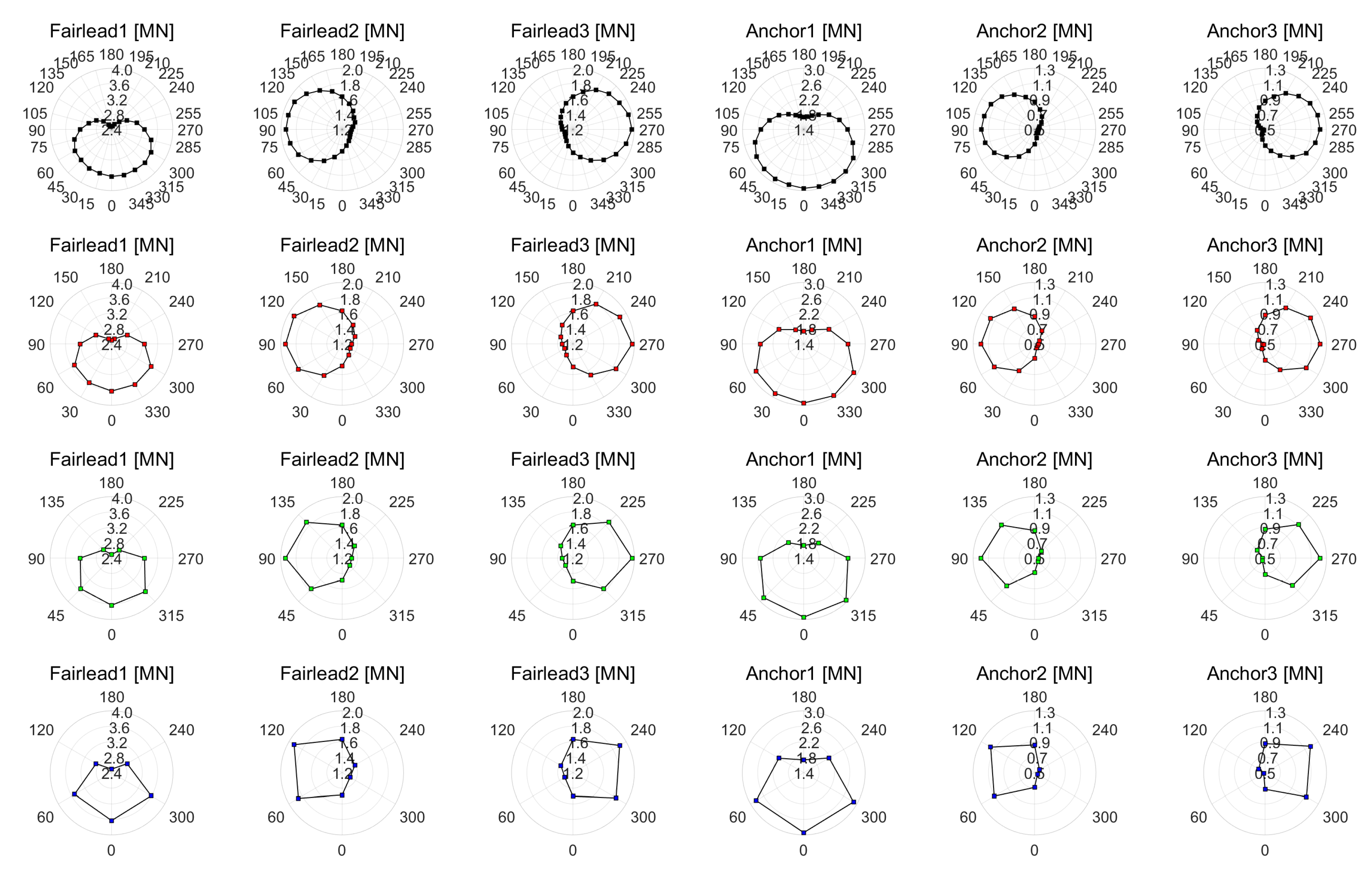
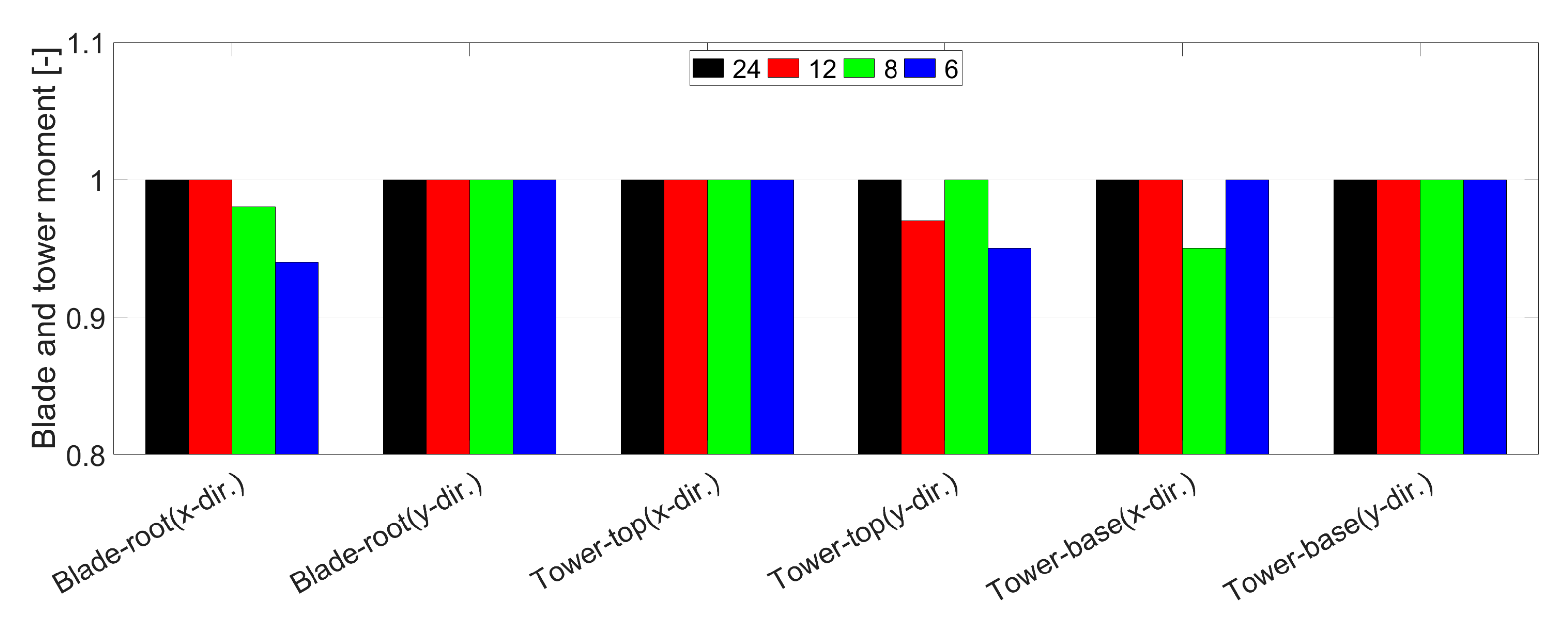
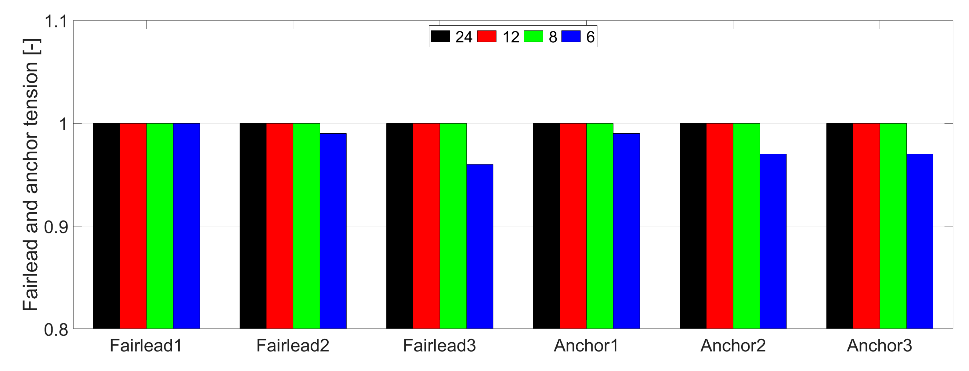
3.3. Interval Angle of Incidence of Wind and Waves
4. Conclusions and Future Work
4.1. Conclusions
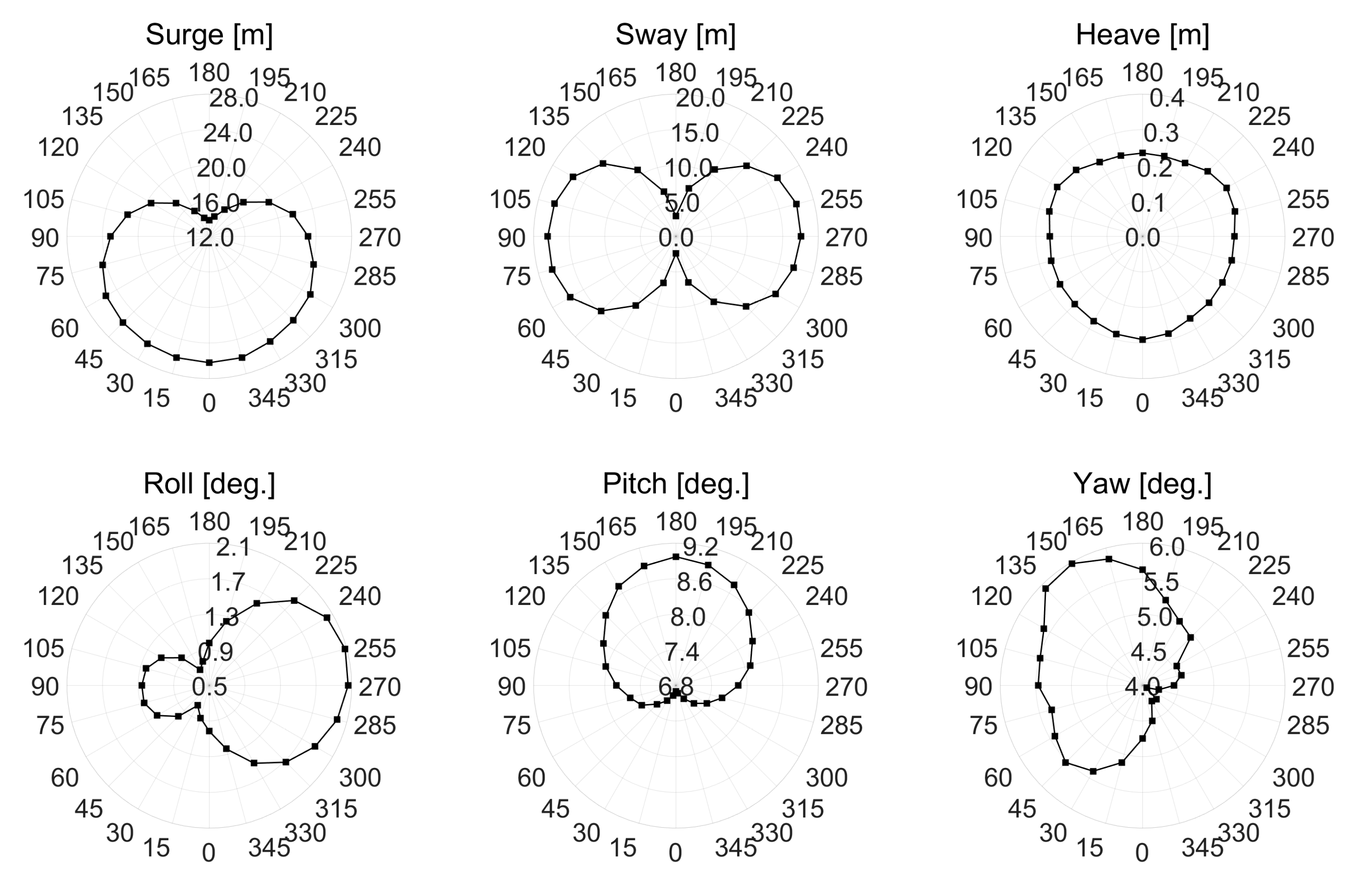
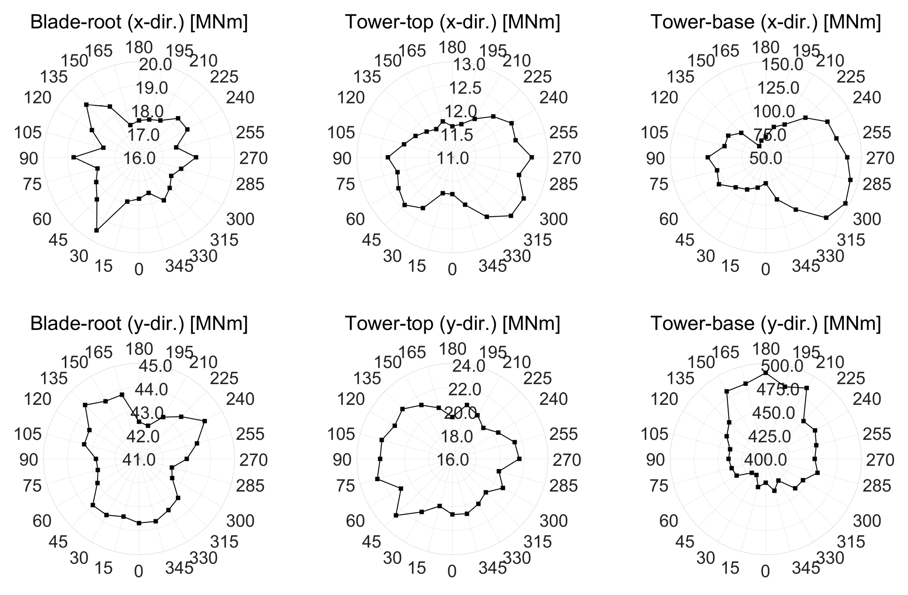
- In the results of the platform’s motion, the platform’s motion occurred asymmetrically, and in particular, it could be seen that the platform’s yaw motion occurred at more than 4 degrees even when the wind and waves acted in the forward direction due to the gyroscope phenomenon and the aerodynamic instability due to the turbulent wind. Since this can be larger in a larger turbine, it is necessary to confirm the load though a numerical simulation. In the results of the blade and tower’s moments, is the results were very asymmetrical depending on the direction of the incoming wind and waves. Since the platform was submerged in water, but since the blade and tower directly faced the wind, it appeared more asymmetrical compared to the platform’s motion.
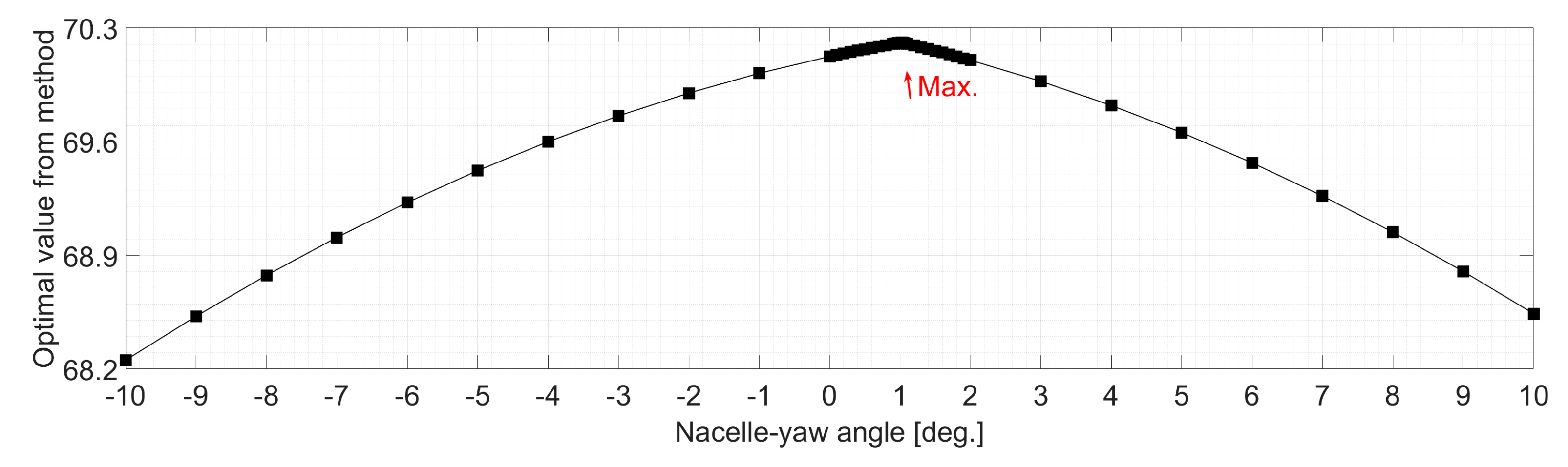
- In a large floating offshore wind turbine system, a certain platform’s yaw motion occurred even when the wind and waves acted in the forward direction due to the gyroscope phenomenon and the aerodynamic instability due to the turbulent wind. In order to alleviate this phenomenon, some adjustment of the nacelle–yaw angle could be made, which could maximize the power as well as minimize the platform’s yaw motion, tower top’s yaw moment and tower base’s yaw moment. In this study, a multiobjective optimization function was used to find the optimal value of the nacelle–yaw angle, and it was found that the optimal value of the nacelle–yaw angle was 1.02 degrees.
- In the results of the interval angle of incidence of the wind and waves, even the 30-degree interval angle of incidence of the wind and waves suggested by Barj et al. and IEC61400-3-2 was sufficient to confirm the maximum value of each parameter. However, the load diagrams plots of the blade and tower’s moments were very asymmetrical and spiky. This means that the maximum value may not be predictable at an interval of 30 degrees. In fact, the tower top’s moment (y-dir.) in this study did not predict the maximum value at an interval of 30 degrees.
4.2. Future Work
Author Contributions
Funding
Institutional Review Board Statement
Informed Consent Statement
Data Availability Statement
Acknowledgments
Conflicts of Interest
References
- Bachynski, E.E.; Kvittem, M.I.; Luan, C.; Moan, T. Wind-wave misalignment effects on floating wind turbines: Motions and tower load effects. J. Offshore Mech. Arct. Eng. 2014, 136, 4. [Google Scholar] [CrossRef]
- Jonkman, J. Definition of the Floating System for Phase IV of OC3; National Renewable Energy Lab. (NREL): Golden, CO, USA, 2010.
- Robertson, A.; Jonkman, J.; Masciola, M.; Song, H.; Goupee, A.; Coulling, A.; Luan, C. Definition of the Semisubmersible Floating System for Phase II of OC4; National Renewable Energy Lab. (NREL): Golden, CO, USA, 2014.
- Barj, L.; Jonkman, J.M.; Robertson, A.; Stewart, G.M.; Lackner, M.A.; Haid, L.; Matha, D.; Stewart, S.W. Wind/wave misalignment in the loads analysis of a floating offshore wind turbine. In Proceedings of the 32nd ASME Wind Energy Symposium, Prince George’s County, MD, USA, 13–17 January 2014. [Google Scholar]
- Stewart, G.M. Design load analysis of two floating offshore wind turbine concepts. Ph.D. Thesis, University of Massachusetts, Amherst, MA, USA, 2016. [Google Scholar]
- International Electrotechnical Commission. Wind Energy Generation Systems-Part 3–2: Design Requirements for Floating Offshore Wind Turbines; IEC TS: Geneva, Switzerland, 2019; pp. 61400–61403. [Google Scholar]
- Oh, S.; Iwashita, T.; Suzuki, H. Numerical modelling and validation of a semisubmersible floating offshore wind turbine under wind and wave misalignment. J. Phys. Conf. Ser. 2018, 1104, 012010. [Google Scholar] [CrossRef]
- Lyu, G.; Zhang, H.; Li, J. Effects of incident wind/wave directions on dynamic response of a SPAR-type floating offshore wind turbine system. Acta Mech. Sin. 2019, 35, 954–963. [Google Scholar] [CrossRef] [Green Version]
- Jonkman, J.; Butterfield, S.; Musial, W.; Scott, G. Definition of a 5-MW Reference Wind Turbine for Offshore System Development (No. NREL/TP-500-38060); National Renewable Energy Lab. (NREL): Golden, CO, USA, 2009.
- Li, X.; Zhu, C.; Fan, Z.; Chen, X.; Tan, J. Effects of the yaw error and the wind-wave misalignment on the dynamic characteristics of the floating offshore wind turbine. Ocean. Eng. 2020, 199, 106960. [Google Scholar] [CrossRef]
- Özinan, U.; Kretschmer, M.; Lemmer, F.; Cheng, P.W. Effects of yaw misalignment on platform motions and fairlead tensions of the OO-Star Wind Floater Semi 10MW floating wind turbine. J. Phys. Conf. Ser. 2020, 1618, 052081. [Google Scholar] [CrossRef]
- Jonkman, J.M.; Buhl, M.L. FAST user’s guide. Gold. CO Natl. Renew. Energy Lab. 2005, 365, 366. [Google Scholar]
- Borg, M.; Mirzaei, M.; Brendmose, H. D1. 2 Wind Turbine Models for the Design; DTU, Public LIFES50 D; DTU: Roskilde, Denmark, 2015; p. 1. [Google Scholar]
- Pegalajar-Jurado, A.; Bredmose, H.; Borg, M.; Straume, J.G.; Landbø, T.; Andersen, H.S.; Yu, W.; Müller, K.; Lemmer, F. State-of-the-art model for the LIFES50+ OO-Star Wind Floater Semi 10MW floating wind turbine. J. Phys. Conf. Ser. 2018, 1104, 012024. [Google Scholar] [CrossRef] [Green Version]
- Yu, W.; Müller, K.; Lemmer, F.; Bredmose, H.; Borg, M.; Sanchez, G.; Landbo, T. Public Definition of the Two LIFES50+ 10MW Floater Concepts; LIFES50+ Deliverable: Stuttgart, Germany, 2017. [Google Scholar]
- Jonkman, B.J. TurbSim User’s Guide; National Renewable Energy Lab.(NREL): Golden, CO, USA, 2006.
- Blusseau, P.; Patel, M.H. Gyroscopic effects on a large vertical axis wind turbine mounted on a floating structure. Renew. Energy 2012, 46, 31–42. [Google Scholar] [CrossRef]
- Philippe, M.; Babarit, A.; Ferrant, P. Modes of response of an offshore wind turbine with directional wind and waves. Renew. Energy 2013, 49, 151–155. [Google Scholar] [CrossRef] [Green Version]


| Parameter | Unit | Value |
|---|---|---|
| Rotor orientation | (-) | Clockwise, upwind |
| Rated power | (MW) | 10.0 |
| Rotor diameter | (m) | 178.3 |
| Hub height | (m) | 119.0 |
| Cut-in, rated, cut-out wind speed | (m/s) | 4.0, 11.4, 25.0 |
| Minimum, maximum rotor speed | (rpm) | 6.0, 9.6 |
| Rotor mass | (kg) | 228,000 |
| Nacelle mass | (kg) | 446,000 |
| Parameter | Unit | Value |
|---|---|---|
| Overall substructure mass (excl. tower, mooring) | (kg) | 21,709,000 |
| Centre of mass (CM) below MSL | (m) | 15.255 |
| Substructure roll inertia about CM | (kgm2) | 9,430,000,000 |
| Substructure pitch inertia about CM | (kgm2) | 9,430,000,000 |
| Substructure yaw inertia about CM | (kgm2) | 16,300,000,000 |
| Tower base interface above MSL | (m) | 11.0 |
| Draft at equilibrium position with mooring (no thrust) | (m) | 22.0 |
| Displaced water volume | (m3) | 23,509 |
| Centre of buoyancy below MSL | (m) | 14.236 |
| Parameter | Unit | Value |
|---|---|---|
| Number of lines | (-) | 3 |
| Angle between adjacent lines | (deg.) | 120 |
| Vertical position of fairleads above MSL | (m) | 9.5 |
| Radius to anchors from platform centerline | (m) | 691 |
| Radius to fairleads from platform centerline | (m) | 44 |
| Pretension | (N) | 1,670,000 |
| Case # | Wind | Wave | Control | |
|---|---|---|---|---|
| Rotor Speed | Blade Pitch Angle | |||
| Case 1 | - | - | 9.6 rpm (fixed) | 0° (fixed) |
| Case 2 | - | HS 2.84 m, TP 7.25 s | ||
| Case 3 | 11.4 m/s (Steady) | 9.4~9.8 rpm (Variable) | 0~1° (Variable) | |
| Case 4 | HS 2.84 m, TP 7.25 s | |||
| Case 5 | 11.4 m/s (Turbulent) | |||
| Case 6 | HS 2.84 m, TP 7.25 s | |||
| Number of Bins | Interval Angle (°) | Angles between the Wind and Waves (°) |
|---|---|---|
| 24 | 15 | 0, 15, 30, …, 315, 330, 345 |
| 12 | 30 | 0, 30, 60, 90, 120, 150, 180, 210, 240, 270, 300, 330 |
| 8 | 45 | 0, 45, 90, 135, 180, 225, 270, 315 |
| 6 | 60 | 0, 60, 120, 180, 240, 300 |
Publisher’s Note: MDPI stays neutral with regard to jurisdictional claims in published maps and institutional affiliations. |
© 2022 by the authors. Licensee MDPI, Basel, Switzerland. This article is an open access article distributed under the terms and conditions of the Creative Commons Attribution (CC BY) license (https://creativecommons.org/licenses/by/4.0/).
Share and Cite
Ahn, H.; Ha, Y.-J.; Cho, S.-g.; Lim, C.-H.; Kim, K.-H. A Numerical Study on the Performance Evaluation of a Semi-Type Floating Offshore Wind Turbine System According to the Direction of the Incoming Waves. Energies 2022, 15, 5485. https://doi.org/10.3390/en15155485
Ahn H, Ha Y-J, Cho S-g, Lim C-H, Kim K-H. A Numerical Study on the Performance Evaluation of a Semi-Type Floating Offshore Wind Turbine System According to the Direction of the Incoming Waves. Energies. 2022; 15(15):5485. https://doi.org/10.3390/en15155485
Chicago/Turabian StyleAhn, Hyeonjeong, Yoon-Jin Ha, Su-gil Cho, Chang-Hyuck Lim, and Kyong-Hwan Kim. 2022. "A Numerical Study on the Performance Evaluation of a Semi-Type Floating Offshore Wind Turbine System According to the Direction of the Incoming Waves" Energies 15, no. 15: 5485. https://doi.org/10.3390/en15155485
APA StyleAhn, H., Ha, Y.-J., Cho, S.-g., Lim, C.-H., & Kim, K.-H. (2022). A Numerical Study on the Performance Evaluation of a Semi-Type Floating Offshore Wind Turbine System According to the Direction of the Incoming Waves. Energies, 15(15), 5485. https://doi.org/10.3390/en15155485