Article

Electromagnetic Design and Analysis of Permanent Magnet Linear Synchronous Motor

1
Key Laboratory of CNC Equipment Reliability, Ministry of Education, Jilin University, Changchun 130022, China
2
College of Mechanical and Aerospace Engineering, Jilin University, Changchun 130022, China
*
Author to whom correspondence should be addressed.
Energies 2022, 15(15), 5441; https://doi.org/10.3390/en15155441
Submission received: 7 June 2022 / Revised: 5 July 2022 / Accepted: 21 July 2022 / Published: 27 July 2022
(This article belongs to the Section F: Electrical Engineering)

Abstract

:
Since permanent magnet linear synchronous motors are widely used in fatigue testing, in this paper, the thrust of a permanent magnet linear synchronous motor (PMLSM) is amplified more than 10 times by the method of resonance. Firstly, the air gap magnetic field is analyzed by the equivalent magnetization current method (EMC), the electromagnetic thrust is calculated, and the expression is given by the Maxwell tensor method. The vibration analysis of the whole machine is used to obtain the conditions under which the motor resonates. The dynamic and static characteristics of the motor are analyzed through finite element simulation, the results of the motor design are judged to be reasonable, and the theoretical calculation results are compared with the simulation results to verify the accuracy of the theoretical calculation. The accuracy of the simulation results is verified by static force experiments. Finally, the rated thrust of the motor was enlarged more than 10 times by resonance experiments.

1. Introductions

In recent years, with the development of permanent magnet materials, the development and application of linear motors is very rapid. Compared with rotating motors, linear motors have the advantages of simple structure, high precision, high speed, and long life, and are widely used in industrial, civil, military, and other linear motion occasions. The structure of linear motors is diverse, among which permanent magnet linear synchronous motors are widely used due to their high thrust and high efficiency [1,2,3,4,5]. Whether there is an iron core in the permanent magnet synchronous linear motor has a great impact on the dynamic and static characteristics of the motor, compared with the iron-free linear motor, the iron core linear motor has a large thrust and high rigidity, suitable for high load, and the heat dissipation effect is good, the cost is low.
The research on linear motors at home and abroad focuses on magnetic field analysis, thrust and thrust fluctuation optimization, temperature field simulation, etc. The literature [6] analyzes the magnetic field distribution of a permanent magnet linear synchronous motor with a double air gap structure. The literature [7] uses a new method of spatial harmonic fields to analyze magnetic fields instead of the equivalent magnetization current method. The literature [7,8,9] uses the equivalent magnetization current method and the equivalent magnetization strength method to analyze the magnetic field of the motor. The magnetic field is calculated using the subdomain method, which takes into account the end effect of the motor and calculates the thrust in [10,11]. The electromagnetic thrust is calculated using the Maxwell tensor method in [12,13]. In The literature [14] a 3D finite element modeling of a unilateral non-ferrous core hybrid magnetized PMLSM and the analysis and calculation of the magnetic flux density and thrust characteristics of the no-load air gap are calculated. The literature [15] committed to the study of a high-thrust PMLSM, analyzing the effect of motor size on motor thrust and normal force and verifying it through finite elements. A new optimization method is proposed to analyze thrust and compare it with experimental results in [16]. Literature [17] designed a fault-tolerant permanent magnet linear synchronous motor and designed electromagnetic parameters and analyzed motor performance. The literature [18] performs electromagnetic design of bilateral permanent magnet linear synchronous motors and compared with the single-sided linear motor, the linear motor with the bilateral structure is verified to have better performance. A new type of high-temperature superconducting flux modulated linear motor is proposed in [19], compared with the traditional linear motor, the motor has a larger thrust and smaller thrust fluctuations, and finally, the motor structure parameters are optimized by finite element analysis and genetic algorithms. The transverse flux linear oscillation motor with a moving stator is taken as the research object, and the vibration characteristics of the motor are analyzed and calculated in [20]. The electromagnetic and vibration characteristics of transverse flux linear oscillatory motors with different magnetization methods are compared and analyzed in [21].
To obtain the large thrust of the motor, this paper proposes a resonant method to amplify the thrust, therefore this paper takes the electromagnetic thrust as the design goal of the unilateral PMLSM electromagnetic design. Through the theoretical analysis of magnetic field and thrust and the comparison of finite element results and performance, the rationality of the motor design is verified, as well as static force experiments to verify the accuracy of simulation results. Through the vibration analysis of the whole machine, it is concluded that the output thrust can be amplified when the input frequency is consistent with the vibration frequency of the whole machine. Finally, the output thrust of the motor is amplified more than 10 times by resonance experiments. This article is divided into 6 sections in total. The structure and parameters of PMLSM are given in Section 2. In Section 3, magnetic field analysis of the motor is performed using the equivalent magnetization current method and thrust analysis calculations are performed using the Maxwell tensor method. In Section 4, finite element analysis of motor no-load and load results is performed by electromagnetic field simulation. In Section 5, the static force experiment is performed on the motor, and the rationality of the motor design is further verified by calculating the thrust constant of the motor. Finally, the full text is summarized in Section 6.

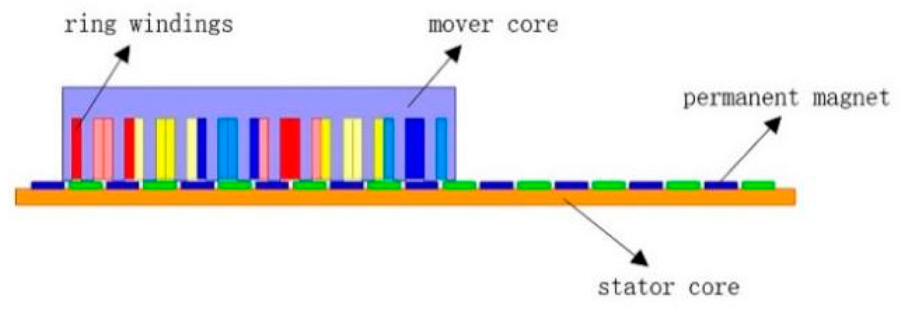
2. PMLSM Structure and Parameters

According to the actual motor according to a certain proportion of the motor structure design, the motor model is shown in Figure 1. The motor is composed of a primary and secondary, and the primary is composed of a mover core and windings, which is the moving element part, the windings are wound around the mover’s teeth, the potential star diagram of the tank, and the winding order are shown in Figure 2. The secondary stage is composed of a stator core and a permanent magnet, which is the stator part, permanent magnets are arranged at a certain distance on the stator core, the permanent magnet is magnetized in the direction of radial magnetization and adjacent permanent magnets have opposite polarity, the slot poles selected by PMLSM are 12 slots and 10 poles. The primary core material is DW465_50, the secondary core material is steel_1010, the permanent magnet material is NdFe35, and the coil winding material is copper, the parameters of PMLSM are shown in Table 1.

3. PMLSM Theoretical Analysis

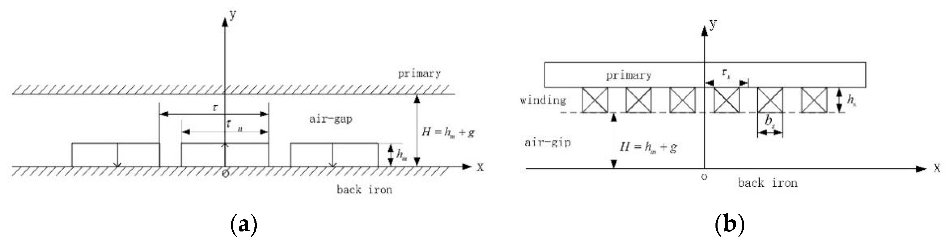
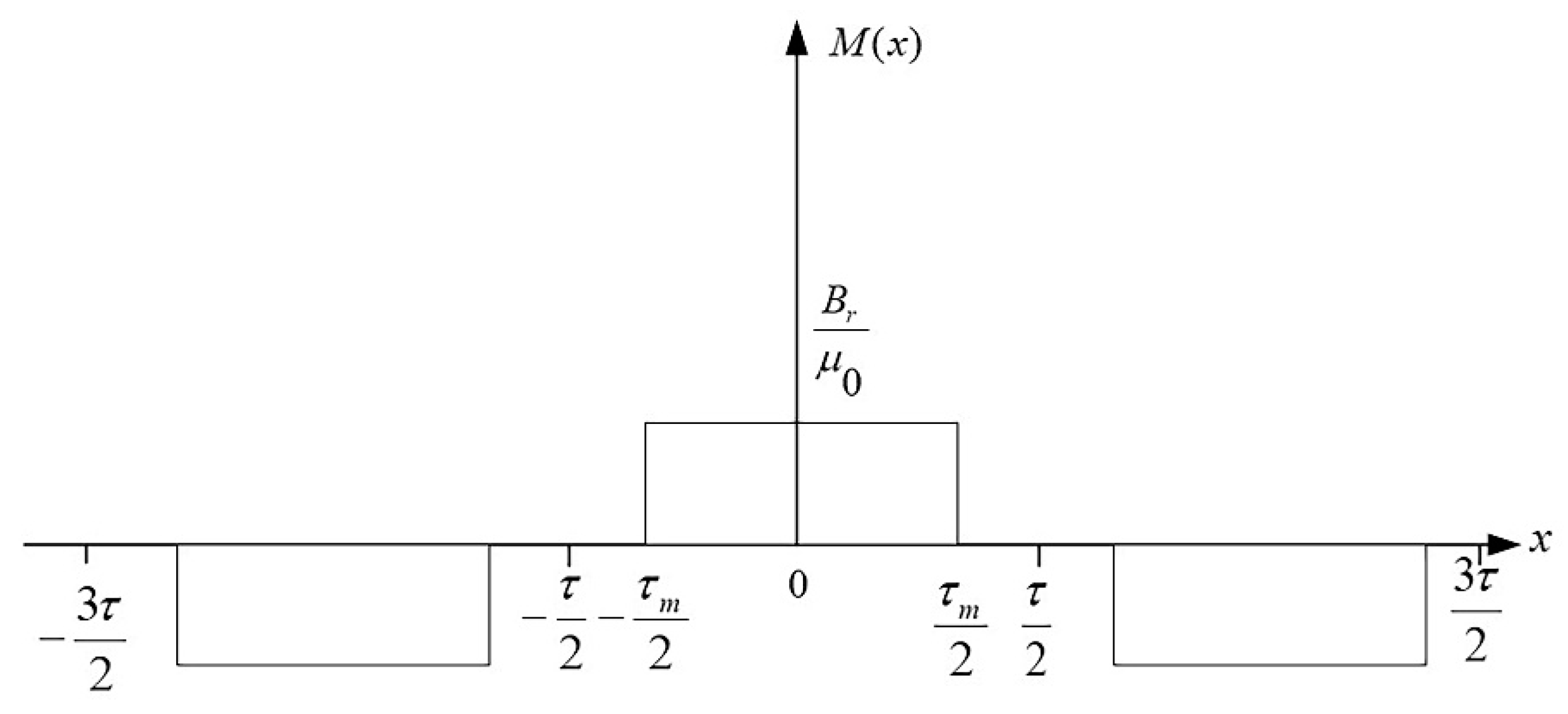
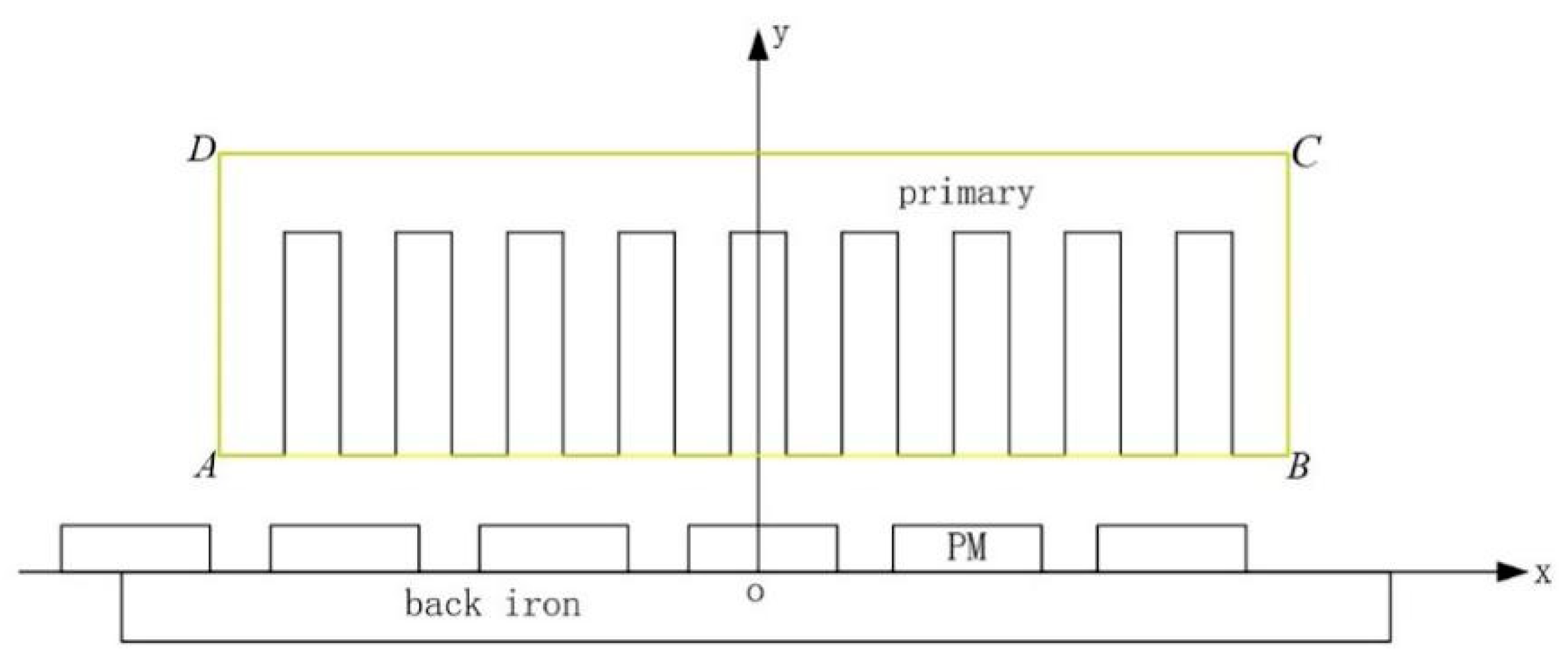
3.1. Magnetic Field Analysis

In this paper, the equivalent magnetization current method is used to analyze and calculate the magnetic field of the motor. The PMLSM magnetic field analysis model is shown in Figure 3 and proposes the following assumptions [22]:
(1) The magnetic field changes in the z-axis direction, ignoring the transverse edge effect;
(2) The permeability of primary and secondary cores is infinite;
(3) The demagnetization curve of the permanent magnet basically coincides with the recovery line;
(4) The demagnetization curve of the permanent magnet material is straight, and the permanent magnet is magnetized relatively uniformly.
The model of the magnet magnetization intensity is shown in Figure 4:
According to the above assumptions, the magnetization intensity is expanded into each harmonic according to the Fourier series:
M ( x ) = 4 B r π μ 0 n = 1 ( 1 ) n + 1 1 2 n 1 sin ( 2 n 1 ) π τ m 2 τ cos ( 2 n 1 ) π x τ
where μ 0 is the vacuum permeability, B r is the permanent magnet residual magnet, τ is the polar distance, and τ m is the permanent magnet width.
The equivalent magnetization current density of the permanent magnet is:
J m ( x ) = 4 B r τ μ 0 n = 1 ( 1 ) n + 1 sin ( 2 n 1 ) π τ m 2 τ sin ( 2 n 1 ) π x τ
When permanent magnets act alone, the following magnetic field equations can be established according to Maxwell’s equations:
In the air gap area:
2 A m 1 x 2 + 2 A m 1 y 2 = 0
In the permanent magnet area:
2 A m 2 x 2 + 2 A m 2 y 2 = μ 0 J m
The separation variable method is used to obtain a general solution:
{ A m 1 = [ A 1 c h k n y + B 1 s h k n y ] · [ M 1 cos k n x + N 1 sin k n x ]   A m 2 = [ A 2 c h k n y + B 2 s h k n y ] · [ M 2 cos k n x + N 2 sin k n x ]   4 B r τ π 2 n = 1 ( 1 ) n + 1 1 ( 2 n 1 ) 2 sin ( 2 n 1 ) π τ m 2 τ sin ( 2 n 1 ) π x 2 τ
Equation (6) can be obtained according to the boundary condition:
{ B 1 = F n · s h k n h m   A 1 = F n · c h k n H s h k n H · s h k n h m A 2 = F n [ c h k n h m c h k n H s h k n H · s h k n h m ] = F n s h k n H · s h k n ( H h m )
In the above equation: k n = ( 2 n 1 ) π τ , F n = 4 B r τ π 2 n = 1 ( 1 ) n + 1 1 ( 2 n 1 ) 2 sin ( 2 n 1 ) π τ m 2 τ .
The vector magnetic potential and magnetic induction intensity of the air gap magnetic field region can be obtained, respectively:
{ A m 1 = F n s h k n ( H h m ) s h k n H · sin k n x · c h k n y F n sin k n x   B m 1 x = A 1 y = F n k n s h k n ( H h m ) s h k n H · sin k n x · s h k n y   B m 1 y = A 1 x = F n k n s h k n ( H h m ) s h k n H · cos k n x · c h k n y + F n k n cos k n x
The vector magnetic potential and magnetic induction intensity of the permanent magnet region are, respectively:
{ A m 2 = F n s h k n h m s h k n H · sin k n x · c h k n ( H y ) B m 2 x = A 2 y = F n k n s h k n h m s h k n H · sin k n x · s h k n ( H y ) B m 2 y = A 2 x = F n k n s h k n h m s h k n H · cos k n x · c h k n ( H y )
The equivalent magnetization current of the armature winding is:
J s ( x ) = 2 n π n = 1 [ cos n π ( 3 + k ) 6 cos n π ( 3 k ) 6 ] · { J a sin [ n π 3 τ s ( x + τ s ) ] + J b sin [ n π 3 τ s x ] + J c sin [ n π 3 τ s ( x τ s ) ] }
In the above equation: J a ,   J b ,     J c is the current density of the windings, the expression is as follows:
{ J a = N 1 i a b s h s J b = N 1 i b b s h s J c = N 1 i b b s h s
{ i a = I sin ( ω t + φ )   i b = I sin ( ω t + φ 2 π 3 ) i c = I sin ( ω t + φ + 2 π 3 )
In the above equation: N 1 is the number of coil turns; I is the amplitude of the current; ω is the motor angular frequency; φ is the phase angle.
For armature windings acting alone, the following magnetic field equations can be established according to Maxwell’s equations:
In the air gap area:
2 A s 1 x 2 + 2 A s 1 y 2 = 0
In the armature winding area:
2 A s 2 x 2 + 2 A s 2 y 2 = μ 0 J s
By using the method of separating variables, a general solution can be obtained:
{ A s 1 = [ a 1 c h p n y + b 1 s h p n y ] · [ m 1 cos p n x + n 1 sin p n x ] A s 2 = [ a 2 c h p n y + b 2 s h p n y ] · [ m 2 cos p n x + n 2 sin p n x ] + 18 τ s 2 μ 0 n 3 π 3 n = 1 [ cos n π ( 3 k ) 6 cos n π ( 3 + k ) 6 ] · { J a cos [ n π 3 τ s ( x + τ s ) ] + J b cos ( n π 3 τ s x ) + J c cos [ n π 3 τ s ( x τ s ) ] }
Equation (15) can be obtained according to the boundary condition as:
{ a 1 = G n s h p n h s s h p n ( h s + H ) e ( p n H ) 2 a 2 = G n c h p n ( h s + H ) s h p n H s h p n ( h s + H ) e ( p n H ) 2 b 2 = G n s h p n H e ( p n H ) 2
In the above equation: p n = n π 3 τ s ,     G n = 18 τ s 2 μ 0 n 3 π 3 n = 1 [ cos n π ( 3 + k ) 6 cos n π ( 3 k ) 6 ] , k = b s τ s .
The vector magnetic potential and magnetic flux density in the air gap region are, respectively, as follows:
{ A s 1 = G n s h p n h s s h p n ( h s + H ) e ( p n H ) 2 c h p n y · { J a sin [ p n ( x + τ s ) ] + J b sin ( p n x ) + J c sin [ p n ( x τ s ) ] } B s 1 x = G n p n s h p n h s s h p n ( h s + H ) e ( p n H ) 2 s h p n y · { J a sin [ p n ( x + τ s ) ] + J b sin ( p n x ) + J c sin [ p n ( x τ s ) ] } B s 1 y = G n p n s h p n h s s h p n ( h s + H ) e ( p n H ) 2 c h p n y · { J a cos [ p n ( x + τ s ) ] + J b cos ( p n x ) + J c cos [ p n ( x τ s ) ] }
The vector magnetic potentials and magnetic flux densities of the armature winding region are as follows:
{ A s 2 = G n [ s h p n H e ( p n H ) 2 s h p n ( h s + H ) c h p n ( h s + H y ) 1 ] · { J a sin [ p n ( x + τ s ) ] + J b sin ( p n x ) + J c sin [ p n ( x τ s ) ] } B s 2 x = G n [ s h p n H e ( p n H ) 2 s h p n ( h s + H ) s h p n ( h s + H y ) 1 ] · { J a sin [ p n ( x + τ s ) ] + J b sin ( p n x ) + J c sin [ p n ( x τ s ) ] } B s 2 y = G n [ s h p n H e ( p n H ) 2 s h p n ( h s + H ) s h p n ( h s + H y ) 1 ] · { J a cos [ p n ( x + τ s ) ] + J b cos ( p n x ) + J c cos [ p n ( x τ s ) ] }

3.2. Electromagnetic Thrust Calculation

Based on the analysis of the magnetic field, the Maxwell tensor method is used to analyze and calculate the horizontal electromagnetic thrust of PMLSM. The method is to equate the volumetric electromagnetic force received by any region of the stressed object to the tension on the surface outside the area of the object, and then obtain the sum of the electromagnetic forces by integrating the equal density of the magnetic field tension tensor. The integral path for calculating the electromagnetic thrust by this method only contains a primary iron core, and the integral path selected in this paper is A-B-C-D, the PMLSM integration path is shown in Figure 5. Using Maxwell’s method to calculate the electromagnetic force in the two-dimensional magnetic field, the total electromagnetic thrust of the surface can be obtained as follows:
F = D μ 0 s [ B ( B · n ) 1 2 B 2 n ] d s
D Is the length of the motor in the z-axis direction,   μ 0 = 4 π × 10 7 the n and B expressions are as follows:
{ n = n x a x + n y a y B = B x a x + B y a y
a x and a y are unit vectors in the x and y directions, respectively.   n x and n y are projections of the normal vectors of the surface in the x and y directions, respectively.
The horizontal and normal electromagnetic force magnitude of the motor can be found as follows:
{ F x = D 2 μ 0 s [ ( B x 2 B y 2 ) n x + 2 B x B y n y ] d s F y = D 2 μ 0 s [ ( B y 2 B x 2 ) n y + 2 B x B y n x ] d s
where B x and B y are tangential and normal magnetic flux density, respectively, and s is the integral path, this article focuses on the horizontal electromagnetic thrust.

3.3. Vibration Analysis

The linear motor mechanical loading model is shown in Figure 6.
Replace the mass of the mover part with mass block m , replace the elastic element and related components and dampers with springs with a stiffness k and damping c , respectively, and use F ( t ) to represent the electromagnetic force generated by the motor. This dynamic model can be regarded as a single-degree-of-freedom forced vibration system according to vibration theory, so the alternating load test applied to the specimen by this actuator is fully in line with its vibration theory method. The external excitation of the motor is as follows:
F ( t ) = A 0 cos ω t = k A cos ω
where A 0 is the incentive amplitude,   A is an order with displacement, and   ω is the frequency of excitation. For this mechanical loading model, according to the vibration analysis theory, the equation of motion of the second-order system is:
m x ¨ ( t ) + c x ˙ ( t ) + k x ( t ) = F ( t )
k m = ω n 2 , c m = 2 ξ . ω n is the natural frequency of the system, and ξ is the viscous damping factor. Bring the above expression into the above formula:
x ¨ ( t ) + 2 ξ ω n x ˙ ( t ) + ω n 2 x ( t ) = A ω n 2 cos ω t
Solving Equation (25) can be obtained:
x ( t ) = X cos ( ω t ϕ )
X = A [ 1 ( ω ω n ) 2 ] 2 + ( 2 ξ ω ω n ) 2
ϕ = tan 1 2 ξ ω ω n 1 ( ω ω n ) 2
The derivative of Equation (28) is zero, and its pole position can be derived, that is, the peak point position of the amplitude of the response force with respect to the driving frequency ω :
ω = ω n 1 2 ξ 2
Let β be the magnification factor, the value of which is:
β = 1 [ 1 ( ω ω n ) 2 ] 2 + ( 2 ξ ω ω n ) 2
When driving frequency ω is associated with the natural frequency of the system ω n , the output thrust of the linear motor actuator will be infinitely amplified.

4. Finite Element Analysis

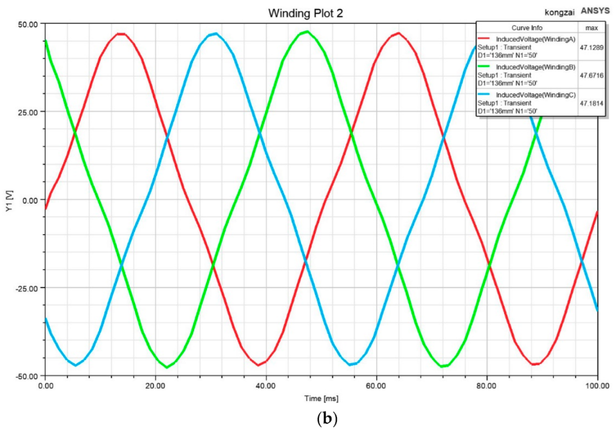
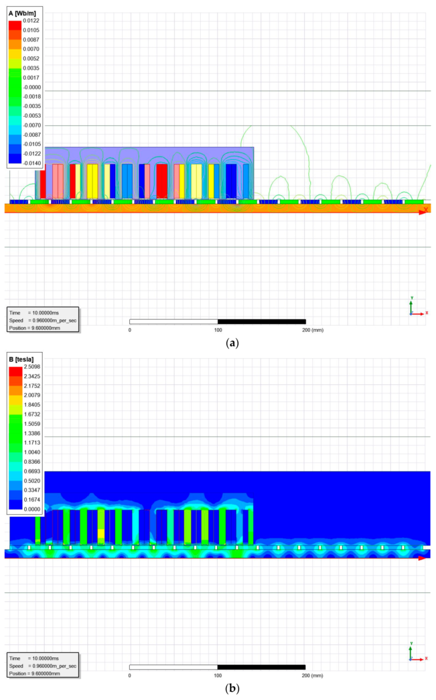
4.1. Analysis of No-Load Simulation Results

No-load is the state in which the coil windings of the motor are not current. The PMLSM flux waveform diagram and the back EMF waveform diagram are shown in Figure 7. It can be seen from the Figure that the sinusoidal rate of the flux waveform is relatively good, reflecting the high performance of the motor, and also confirms that the air gap magnetic flux density is also sinusoidal distribution, and the amplitude of the flux is 0.34 Wb. The back EMF waveform is relatively poorly sinusoidal, and there are mutations in the peaks and troughs, this is not only closely related to the magnetic flux density of the no-load air gap but also has a certain impact on the thrust fluctuations of the motor. In addition, the amplitude of the back EMF is 47 V.
Due to the structural characteristics such as the disconnection and slotting of the primary core, horizontal detent force and normal detent force are generated during operation, and the detent force produces thrust fluctuations during operation, which greatly reduces the performance of the motor. In this paper, the detent force is reduced by optimizing the primary length to suppress the longitudinal end effect. PMLSM horizontal detent force and normal detent force are shown in Figure 8, the horizontal detent force amplitude fluctuates between −74 N and 105 N, the detent force fluctuation amplitude is 179 N, and the average normal detent force is 6.6 KN.
Figure 9 is the result of solving the air gap normal magnetic flux density by the equivalent magnetization current method and finite element method. It can be seen from the figure that both waveforms are positively linear and have a period of twice the polarity of 48 mm. As a result of the finite element solution, the wave has a depression at the cogging groove due to the effect of the cogging effect. As a result of the EMC solution, the waveform is smoother and has the characteristics of a flat top wave. From the figure, it can be obtained that the maximum value of EMC to solve the air gap magnetic density is 1 T, and the finite element method to solve the maximum value of the air gap magnetic density is 1.11 T, and the solution results of the two are basically the same. EMC simplifies the motor model to two dimensions and idealizes some boundary conditions, this method of solving the magnetic flux density of the air gap is relatively simple and is the basis for other solution methods. Furthermore, the finite element analysis solution takes into account the cogging effect, so the solution result is relatively more accurate.
Figure 10 shows the Fourier analysis of the air gap magnetic flux density, the result includes the first 10 harmonic components, the air gap magnetic density fundamental wave amplitude is 0.9647 T, accounting for 86.5% of the maximum air gap magnetic flux density, indicates that the fundamental wave is consistent with the total waveform. Among them, the third and fifth harmonious components are relatively large. Through the above analysis, it can be concluded that the air gap magnetic density waveform is good, all of which are sinusoidal distributions, which not only verifies the accuracy of theoretical calculations but also verifies the design results of the motor are reasonable. In addition, the air gap magnetic density fundamental wave amplitude is relatively large, which can provide a large enough thrust to the motor to meet the design goal of the motor’s electromagnetic thrust.

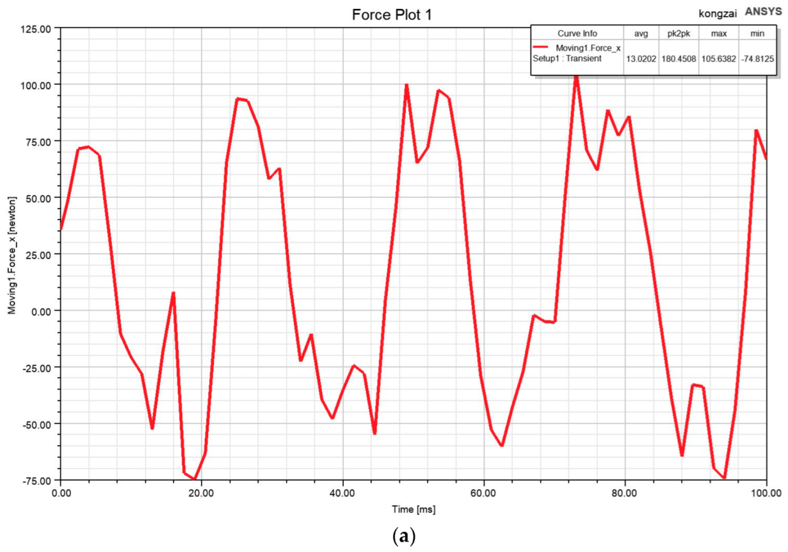
4.2. Analysis of Load Simulation Results

The magnetic field line and magnetic flux density distribution cloud diagram of PMLSM running 0.01 s at a speed of 0.96 m/s are shown in Figure 11. This can be seen in the magnetic field line distribution cloud map, most magnetic field lines travel through a loop of permanent magnets, air gaps, and amateur windings, a small number of magnetic field lines are the components of the permanent magnet in the horizontal direction. Furthermore, it can be seen from the magnetic flux density distribution cloud diagram that the maximum magnetic flux density of the tooth part is 2.3 T, and the maximum magnetic flux density of the primary yoke is 1.6 T, there is some magnetic saturation.
Figure 12 is the result of solving the horizontal electromagnetic thrust of the motor by finite element analysis (FEA) and Maxwell tensor method, respectively. It can be seen from the figure that the average electromagnetic thrust of Maxwell’s tensor solution is 987 N, and the average electromagnetic thrust of the finite element solution is 948 N, the results of the two are basically the same, and the accuracy of the theoretical analysis was verified.

5. Experimental Analysis

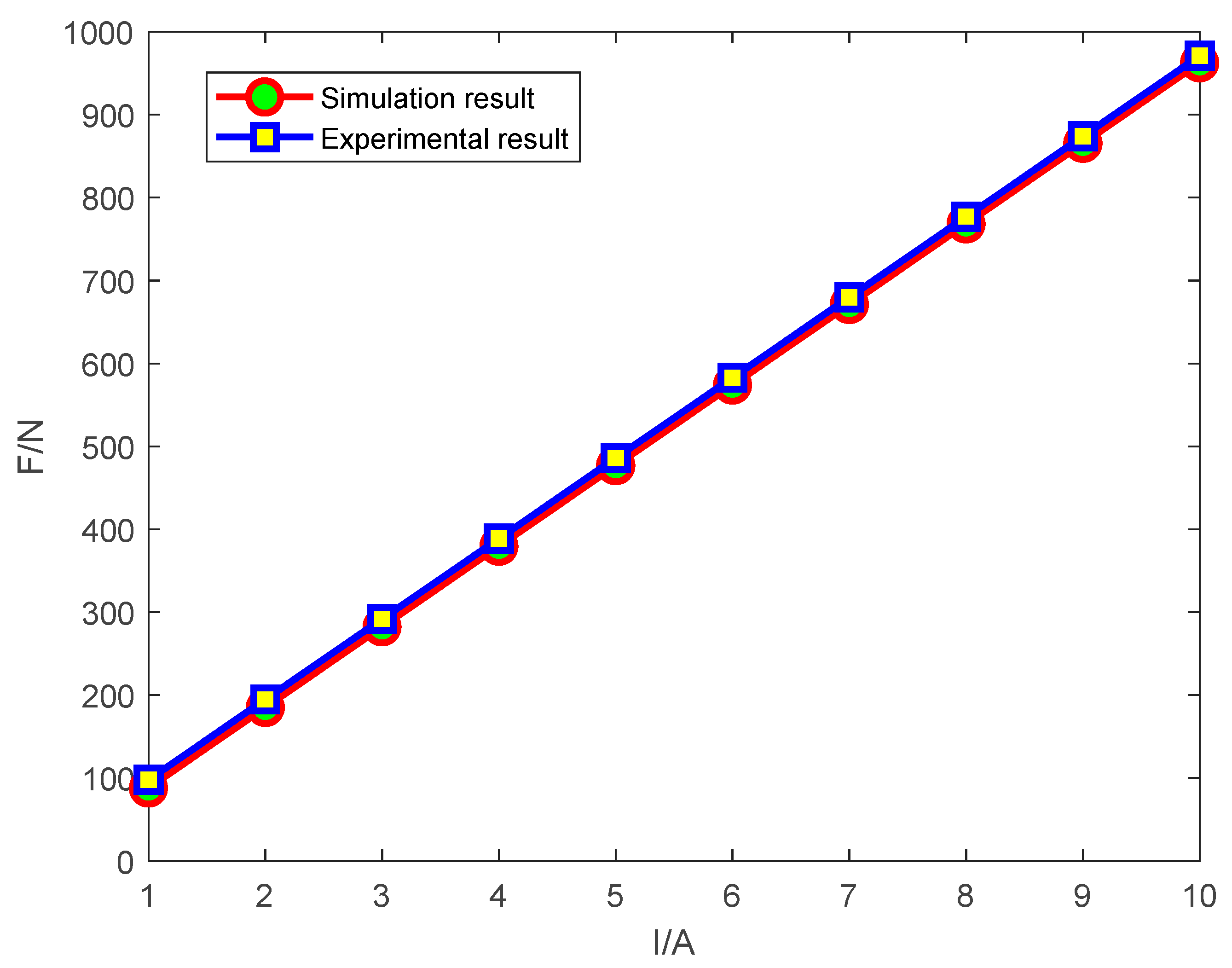
5.1. Thrust Constant Test

The PMLSM experimental platform is shown in Figure 13, which is composed of a whole machine part and a servo drive, of which the whole machine part is composed of a motor body, a pressure sensor, and a force measuring ring.
In this paper, the static force loading test of the unilateral PMLSM is carried out, and the performance of the motor is checked by testing the thrust constant of the motor, and the expression of the thrust constant is as follows:
C F = F I
Simulation and experimental output thrust and thrust constants under different currents are shown in Table 2, in the case of the motor-rated thrust constant of 93 N/A, the simulated thrust constant can be calculated as 97.29 N/A, the error is 4.6%, and the experimental thrust constant is 96.53 N/A, the error is 3.79%, and the error is less than 5%, which verifies that the motor performance is good. The data of motor simulation and experimental output thrust are fitted by the least-squares method as shown in Figure 14, and it can be seen from the figure that the simulation and experimental output thrust curves meet the linear regression equation, and the motor design results are more reasonable. However, as the current increases, the motor is affected by the amateur reaction and temperature, causing the thrust constant decreases gradually.

5.2. Resonance Experiments

In this paper, the resonance amplification experiment of PMLSM is carried out to achieve thrust amplification at the condition of the motor movement speed is 5mm/s, the amplitude of the current is 15 A, the voltage is 230 V, and the running time is 1s at each frequency. First of all, by finding the frequency range when the system is in approximate resonance to determine the resonance point of the system, the input waveform of the actuator is set to a sine wave, the input frequency is within the range of 1–200 Hz, and the frequency corresponding to the output thrust is the resonance point of the system. The fitting curve is shown in Figure 15, the frequency range when the system reaches resonance is about 128 Hz to 132 Hz. By comparing the thrust output at these frequencies, it can be concluded that the resonant frequency of the linear motor actuator is 130 Hz, and the actuator output load is 11.5 KN. The output of the maximum continuous thrust of 950 N relative to the linear motor is approximately 12.1 times the output thrust in the resonant state. Usually, the natural frequency of the component is several thousand HZ, which is much bigger than the system’s natural frequency, so the motor will not be destroyed.

6. Conclusions

In this paper, the electromagnetic design of the unilateral PMLSM is carried out and the structural parameters are given. Furthermore, the magnetic field and electromagnetic thrust of the motor are theoretically analyzed, and mathematical expressions are given by EMC and Maxwell tensor method. Through the vibration analysis of the whole machine, the conditions for the resonance of the motor are obtained. In the case of no-load, the magnetic chain and back EMF are positive linear, the detent force is reasonable, the air gap magnetic flux density waveforms positive linearity, and the theory is consistent with the simulation solution results. In the case of load, most of the magnetic field lines form a closed loop, but there is a certain magnetic saturation in the core part, and the theoretical analysis of electromagnetic thrust is consistent with the simulation results. Through the PMLSM static force test, the thrust constant under the experiment is basically consistent with the simulation solution results, and the errors of both are less than 5%. Through the above analysis, it can be concluded that the motor design results are more reasonable. Finally, through resonance experiments, the thrust was amplified by 12.1 times under the condition that the rated thrust of the motor was 950 N.

Author Contributions

Conceptualization, L.Y., S.C. and J.H. (Jialong He); Data curation, S.C.; Formal analysis, S.C.; Funding acquisition, L.Y.; Investigation, S.C. and H.S.; Methodology, S.C. and J.H. (Jialong He); Project administration, L.Y., J.H. (Jialong He), H.S., J.H. (Jie Huang) and H.T.; Resources, L.Y.; Software, S.C.; Supervision, L.Y.; Validation, S.C., J.H. (Jialong He), H.S. and H.T.; Visualization, S.C.; Writing—original draft, S.C., H.S. and J.H. (Jie Huang); Writing—review & editing, S.C. All authors have read and agreed to the published version of the manuscript.

Funding

This work was supported by the Science and Technology Development Program of Jilin Province (20210201040GX): Research on Electronic High-Frequency Linear Actuator for Accelerated Fatigue Test of Automobile Parts.

Institutional Review Board Statement

Not applicable.

Informed Consent Statement

Not applicable.

Data Availability Statement

Not applicable.

Conflicts of Interest

The authors declare no conflict of interest.

References

  1. Huang, X.Z.; Li, J.; Zhang, C.; Qian, Z.Y.; Li, L.; Gerada, D. Electromagnetic and Thrust Characteristics of Double-sided Permanent Magnet Linear Synchronous Motor Adopting Staggering Primaries Structure. IEEE Trans. Ind. Electron. 2019, 66, 4826–4836. [Google Scholar] [CrossRef]
  2. Huang, X.Z.; Yu, H.C.; Zhou, B.; Li, L.Y.; Gerada, D.; Gerada, C.; Qian, Z.Y. Detent-Force Minimization of Double-Sided Permanent Magnet Linear Synchronous Motor by Shifting One of the Primary Components. IEEE Trans. Ind. Electron. 2020, 67, 180–191. [Google Scholar] [CrossRef]
  3. Shen, Y.; Lu, Q.; Li, H.; Cai, J.; Huang, X.; Fang, Y. Analysis of a Novel Double-Sided Yokeless Multitooth Linear Switched-Flux PM Motor. IEEE Trans. Ind. Electron. 2018, 65, 1837–1845. [Google Scholar] [CrossRef]
  4. Luu, P.T.; Lee, J.-Y.; Kim, J.-W.; Chung, S.-U.; Kwon, S.-M. Magnetic Sensor Design for a Permanent Magnet Linear Motor Considering Edge-Effect. IEEE Trans. Ind. Electron. 2020, 67, 5768–5777. [Google Scholar] [CrossRef]
  5. Tan, Q.; Huang, X.Z.; Li, L.; Wang, M. Magnetic Field Analysis and Flux Barrier Design for Modular Permanent Magnet Linear Synchronous Motor. IEEE Trans. Ind. Electron. 2020, 67, 3891–3900. [Google Scholar] [CrossRef]
  6. Cui, F.; Sun, Z.; Xu, W.; Zhou, W.; Liu, Y. Comparative analysis of bilateral permanent magnet linear synchronous motors with different structures. CES Trans. Electr. Mach. Syst. 2020, 4, 142–150. [Google Scholar] [CrossRef]
  7. Kang, G.-H.; Hong, J.-P.; Kim, G.-T. A novel design of an air-core type permanent magnet linear brushless motor by space harmonics field analysis. IEEE Trans. Magn. 2001, 37, 3732–3736. [Google Scholar] [CrossRef]
  8. Kim, J.; Joo, S.; Hahn, S.; Hong, J.; Kang, D.; Koo, D. Static Characteristics of Linear BLDC Motor Using Equivalent Magnetic Circuit and Finite Element Method. IEEE Trans. Magn. 2004, 40, 742–745. [Google Scholar] [CrossRef]
  9. Liu, X.; Gao, J.; Huang, S.; Lu, K. Magnetic Field and Thrust Analysis of the U-Channel Air-Core Permanent Magnet Linear Synchronous Motor. IEEE Trans. Magn. 2017, 53, 8201504. [Google Scholar] [CrossRef]
  10. Hu, H.; Zhao, J.; Liu, X.; Guo, Y. Magnetic Field and Force Calculation in Linear Permanent-Magnet Synchronous Machines Accounting for Longitudinal End Effect. IEEE Trans. Ind. Electron. 2016, 63, 7632–7643. [Google Scholar] [CrossRef] [Green Version]
  11. Zhu, Z.Q.; Wu, L.J.; Xia, Z.P. An Accurate Subdomain Model for Magnetic Field Computation in Slotted Surface-Mounted Permanent-Magnet Machines. IEEE Trans. Magn. 2010, 46, 1100–1115. [Google Scholar] [CrossRef]
  12. Virtic, P.; Stumberger, B. Analytical Analysis of Magnetic Field and Force Calculation in a Slotless-Type Permanent Magnet Linear Synchronous Machine; Verification with Numerical Analysis. In Proceedings of the 2007 IEEE International Electric Machines & Drives Conference, Cracow, Poland, 6–8 September 2007; pp. 963–968. [Google Scholar]
  13. Bao-Quan, K.; Hong-Xing, W.; Li-Yi, L.; Liang-Liang, Z.; Zhe, Z.; Hai-Chuan, C. The Thrust Characteristics Investigation of Double-Side Plate Permanent Magnet Linear Synchronous Motor for EML. IEEE Trans. Magn. 2009, 45, 501–505. [Google Scholar] [CrossRef]
  14. Zhang, Z.; Shi, L.; Wang, K.; Li, Y. Characteristics investigation of single-sided ironless pmlsm based on Halbach array for medium-speed Maglev train. CES Trans. Electr. Mach. Syst. 2017, 1, 375–382. [Google Scholar] [CrossRef]
  15. Li, C.; Kou, B. Research on Electromagnetic Force of Large Thrust Force PMLSM Used in Space Electromagnetic Launcher. IEEE Trans. Plasma Sci. 2013, 41, 1209–1213. [Google Scholar]
  16. Song, J.; Dong, F.; Zhao, J.; Lu, S.; Li, L.; Pan, Z. A New Design Optimization Method for Permanent Magnet Synchronous Linear Motors. Energies 2016, 9, 992. [Google Scholar] [CrossRef] [Green Version]
  17. Zhao, W.; Cheng, M.; Ji, J.; Cao, R.; Du, Y.; Li, F. Design and Analysis of a New Fault-Tolerant Linear Permanent-Magnet Motor for Maglev Transportation Applications. IEEE Trans. Appl. Supercond. 2012, 22, 5200204. [Google Scholar] [CrossRef]
  18. Zhang, X.M.; Cheng, C.Y.; Lu, Q.F.; Ye, Y.Y.; Tao, X.S. Design and Electromagnetic Analysis of a Double-Sided Permanent Magnet Linear Synchronous Motor. Appl. Mech. Mater. 2013, 416–417, 270–275. [Google Scholar] [CrossRef]
  19. Li, L.; Zhu, G.; Liu, X.; Chen, H.; Jiang, W.; Xue, M. Design and Optimization of a Novel HTS Flux-Modulated Linear Motor Using Halbach Permanent Magnet Arrays. IEEE Trans. Appl. Supercond. 2021, 31, 5203104. [Google Scholar] [CrossRef]
  20. Yue, F.; Sun, Z.; Xu, W.; Li, X. Calculation and analysis of electromagnetic vibration of transverse flux linear oscillation motor with moving stator. In Proceedings of the 13th International Symposium on Linear Drives for Industry Applications (LDIA), Wuhan, China, 1–3 July 2021; pp. 1–4. [Google Scholar] [CrossRef]
  21. Yue, F.; Sun, Z.; Xu, W.; Yang, X. Structure Optimization Design and Analysis of Transverse Flux Linear Oscillation Motor with Moving Stator. In Proceedings of the 13th International Symposium on Linear Drives for Industry Applications (LDIA), Wuhan, China, 1–3 July 2021; pp. 1–5. [Google Scholar] [CrossRef]
  22. Mao, Y.; Sun, Z.; Zhou, W.; Zhuang, Z.; Qian, H. Electromagnetic Design of Toroidal Permanent Magnet Linear Synchronous Motor. IEEE Access 2021, 9, 98005–98012. [Google Scholar] [CrossRef]
Figure 1. PMLSM structure.
Energies 15 05441 g001
Figure 2. Winding arrangement order: (a) Electrical potential star chart of slot; (b) Winding arrangement order.
Energies 15 05441 g002
Figure 3. PMLSM magnetic field analysis model: (a) Permanent magnet magnetic field analysis model; (b) Magnetic field analysis model of armature windings.
Energies 15 05441 g003
Figure 4. Distribution map of magnetization intensity of permanent magnets.
Energies 15 05441 g004
Figure 5. PMLSM integration path.
Energies 15 05441 g005
Figure 6. Linear motor mechanical loading model.
Energies 15 05441 g006
Figure 7. PMLSM flux and back–EMF waveform diagram: (a) Motor flux waveform diagram; (b) Motor back EMF waveform diagram.
Energies 15 05441 g007aEnergies 15 05441 g007b
Figure 8. PMLSM horizontal detent force and normal detent force: (a) PMLSM horizontal detent force; (b) PMLSM normal detent force.
Energies 15 05441 g008aEnergies 15 05441 g008b
Figure 9. No-load air gap magnetic flux density distribution curve: (a) No-load method calculates the solution results for magnetic flux density theory; (b) The result of the no-load method is to solve the finite element of magnetic flux density.
Energies 15 05441 g009aEnergies 15 05441 g009b
Figure 10. Air gap magnetic density Fourier analysis.
Energies 15 05441 g010
Figure 11. PMLSM magnetic field lines and magnetic flux density distribution cloud map: (a) Magnetic field line distribution; (b) Magnetic flux density distribution.
Energies 15 05441 g011
Figure 12. Maxwell stress tensor method and finite element method solution for the horizontal electromagnetic thrust of the motor: (a) Finite element solves for the horizontal electromagnetic thrust of the motor; (b) Maxwell stress tensor method solves for the horizontal electromagnetic thrust of the motor.
Energies 15 05441 g012
Figure 13. PMLSM experimental platform: (a) Motor overall and force measuring device; (b) drive.
Energies 15 05441 g013
Figure 14. Simulation and experimental output thrust curves.
Energies 15 05441 g014
Figure 15. Thrust-frequency fitting curve.
Energies 15 05441 g015
Table 1. PMLSM parameters.
ParameterSymbolValueUnit
Slot width b s 12mm
Slot depth h s 40mm
Tooth width b t 8mm
The length of the mover core L 252mm
The thickness of the mover yoke h 2 20mm
Permanent magnet width τ m 21mm
Permanent magnet height h m 4.4mm
Air gap height g 1mm
Stator core length L 1 500mm
Stator iron yoke thickness h 1 10mm
Polar pitch τ 24mm
Number of coil turns 50
Number of permanent magnets 20
Number of slots 12
Table 2. Comparison of simulation and experimental output thrust at different currents.
Current RMS
A
Simulate Output Thrust
N
Simulation Thrust Constant
N/A
Experimental Output Thrust
N
Experimental Thrust Constant
N/A
199998989
2205102.519698
329598.329197
439097.539298
54859748997.8
657996.558998.1
767496.267696.5
876595.677296.5
986095.588197.8
1094894.896696.6
Publisher’s Note: MDPI stays neutral with regard to jurisdictional claims in published maps and institutional affiliations.

