1. Introduction
The fractured-vuggy carbonate reservoir takes up a large proportion of reserves around the world and thus demonstrates great potential and broad prospects [
1]. It has characteristics of low porosity, low permeability, deep burial depth, and strong heterogeneity [
2]. Particularly, carbonate reservoirs contain numerous irregular cavities, which are different from conventional reservoirs. Reservoir development practices have confirmed that the oil/gas is mainly distributed in caves [
3]. Therefore, how to connect caves is the key issue to successful reservoir development. Typically, fracturing and acidification are used to connect the well and natural caves by forming highly conductive hydraulic fractures. The extension trajectory of hydraulic fractures is affected by natural fractures and karst caves, making the fracture propagation mechanism extremely complicated. The classical fracture propagation theory is no longer applicable, and it is still unclear how hydraulic fracture and a naturally occurring karst cave interact.
In recent years, hydraulic fracture propagation is increasingly gaining popularity. Some most commonly used analytical models, e.g., KGD model [
4,
5], PKN model [
6,
7], UFM model [
8,
9], and the planar 3D model [
10] provide a simple method to predict hydraulic fractures geometry. However, the hypothesis of these analytical models does not satisfy the real reservoirs. Therefore, the analysis of complicated fracture extension relies heavily on numerical simulation techniques. So far, to simulate hydraulic fracture extension in complex media, a variety of methods have been proposed by industrial and academic communities, which can be divided into two major categories of methods, simulation methods based on continuous media and simulation methods based on discontinuous media. For simulation methods based on continuous media, the Extended finite element technique (XFEM) was utilized by Dahi-Taleghani et al. to study complex fracture extension problems [
11]. When the hydraulic fracture’s tip encounters enough tensile stress, the natural fracture opens before it intersects the hydraulic fracture, causing the hydraulic fracture to deflect in both directions along the natural fracture. By introducing a correction factor, Olson et al. [
12] investigated the impact of fracture height on width using the displacement discontinuity approach and developed a multi-cluster fracture extension model with constant fracture height. However, the model assumed that the fluid pressure in the fracture would remain constant. For simulation methods based on discontinuous media, Utilizing the two-dimensional particle discrete element approach, Zhao et al.’s study [
13] employed the PFC software platform to examine how hydraulic fractures interact with natural fractures. Ben et al. [
14] first used the discontinuous deformation analysis method to model hydraulic fracture propagation. By merging the finite element approach with the discrete element method, Zou et al. [
15] developed a comprehensive hydraulic fracture propagation model of shale. They then carefully examined the natural fracture activation conditions and the primary governing elements of net-work fracture development in shale reservoirs.
When studying the propagation of fractures in fractured-vuggy carbonate reservoirs, numerous researchers have simplified the characterization of the reservoir containing caves through a planar elastic circular hole model. Li et al. [
16] modeled hydraulic fracture extension in a fracture-vuggy reservoir based on damage mechanics. The level set function was utilized by Cheng et al. [
17] to describe the karst cave area. On the basis of the extended finite element method (XEFM), it was determined how the horizontal stress difference and cave position affect the interaction pattern between cave and fracture. The findings demonstrated the location of the cave is the key determinant of whether hydraulic fracture can successfully connect with the karst cave reservoir. Based on the element partition approach, Wang et al. [
18] studied the path of fracture propagation and how it interacts with the cave. It demonstrated that the primary factor driving hydraulic fracture extension is the horizontal stress difference. Using the phase-field approach, Liu et al. [
19] studied the impact of cavities on hydraulic fracture extension. They found that the Young modulus of the cave area also plays a profound impact on the fracture extension trajectory. A finite element method was proposed by Pan to study the fracture propagation pattern of fractured-vuggy carbonate reservoir considering the effect of fluid-solid coupling, based on damage mechanics [
20]. A novel seepage-mechanical mathematical model coupling free flow was developed by Luo et al. [
21] to investigate the effect of fluid pressure in the cave on the fracture expansion path. In order to predict how injection pressure and fluid pressure in the cave affect hydraulic fracture expansion trajectory in a fracture-vuggy reservoir, Ye et al. [
22] employed the Finite Element-Meshfree Method.
In most of the above studies, the rock and caves are assumed to be homogeneous material and empty holes that do not fill with any material, respectively. Besides, few of them consider the influence of pore water pressure on rock fracture patterns. The interaction among the stress field, seepage field, and damage evolution will be dynamic continuously during the fracturing process as the hydraulic fracture propagates. The area near the hydraulic fracture will generate new damage units due to the combined action of induced stress and pore water pressure. The rock permeability and stiffness coefficient can change dramatically as a result of damage. The distribution of the local stress field will be also influenced by the increase of permeability and degradation of rock stiffness, which in turn influences the hydraulic fracture propagation path. In this paper, a coupled seepage-stress-damage model for a vuggy carbonate reservoir will be established, according to statistical damage mechanics theory and the finite element method. Through numerical modeling, we will investigate how hydraulic fracture interacts with the cave, considering the influence of pore water pressure, as well as the regularities in how the hydraulic fracture connects with the cave and their controllable factors.
2. Seepage-Stress-Damage Coupling Mathematical Model
In this study, based on Biot theory and modified Terzaghi effective stress principle, the finite element approach is used to build a two-dimensional vuggy reservoir fracture propagation model coupled with seepage-stress-damage. The fracture propagation process is numerically simulated using the RFPA-Flow program. The RFPA-Flow (realistic failure process analysis) program was created by Tang et al. in 2002 [
23] to handle the progressive collapse of heterogeneous, porous rock. Previous studies have confirmed the reliability of this coupled seepage-stress-damage model in RFPA-Flow software [
24,
25,
26,
27,
28,
29,
30,
31,
32,
33]. In this study, the RFPA-Flow software has two major advantages compared to other numerical simulation software [
34]: (1) The RFPA-Flow software considers that the macroscopic nonlinearity is caused by the heterogeneity of the material, and utilizes statistical methods to suggest material homogeneity parameters to convert the complicated macroscopic nonlinearity problem into a straightforward mesoscale linear problem. However, other mechanics software that adopts the assumption of homogeneity simply attributes this complex nonlinear deformation to plastic deformation. (2) When damage occurs when the unit stress reaches the criterion of damage, the RFPA software performs stiffness degradation of the damaged unit. Therefore, the problem of physically nonlinear media can be treated with a continuum media mechanics approach, which can make the hydromechanical field well simulated.
In addition, some assumptions are as follows:
The rock medium is conceptualized as an elastically brittle, inhomogeneous material with residual strength, and the elastic damage theory is used to explain how the rock behaves mechanically when loaded and unloaded [
35].
The calculated model unit’s properties, including elastic modulus and strength, follow certain statistical distributions, such as normal, Weber, uniform, etc. The Weber distribution is chosen for this investigation [
36].
The fluid-solid coupling process in the rock material is governed by the Biot solidification theory [
37].
2.1. Seepage Equation
The seepage equation is governed by Darcy’s law, which is as follows:
where
α is the pore water pressure coefficient,
k is the permeability coefficient,
p is pore fluid pressure, Q is Biot’s constant,
εv is volumetric strain,
k0 is the initial permeability coefficient,
β is the coupling coefficient,
ξ (
ξ > 1) is a parameter that reflects the increase in the multiplicity of element permeability before and after the damage.
2.2. Rock Deformation Equation
The rock medium is considered to be an elastically brittle material with residual strength, and it is also expected that during loading and unloading, the rock medium will behave mechanically in line with the theory of elastic damage mechanics. The equilibrium equation and geometric equation can be expressed by:
where
σ is stress; ρ is density;
u is displacement;
X is a component of body force;
ε is strain.
The Constitutive Equation is
where
δ is the Kronecker constant;
G is the shear modulus.
Elastic damage mechanics state that as the degree of damage increases, the element’s elastic modulus may steadily degrade. The damaged element’s elastic modulus is defined as follows [
38]:
where
E0 is the elastic modulus of the undamaged material,
D is the damage variable, and
E is the elastic modulus of the damaged material.
2.3. Heterogeneity of Rock Medium
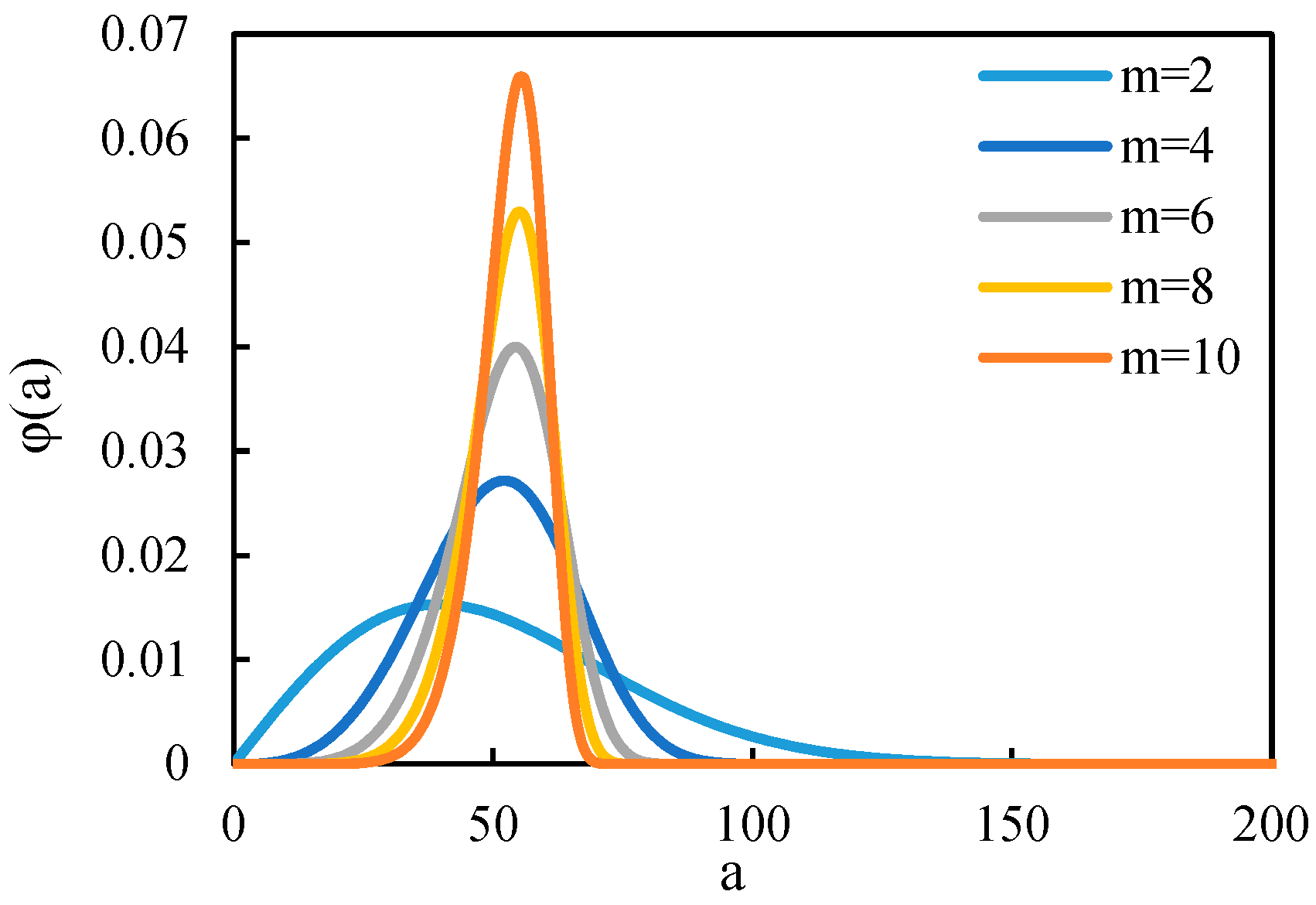
To characterize the heterogeneity of rock materials, the distribution of model mechanical properties is assumed to obey the Weibull distribution [
39].
where
m is the homogeneity index,
a is the element parameter such as the modulus of elasticity, and
a0 is the scale parameter of the distribution.
Equation (6) reflects the heterogeneity distribution of rock mechanical properties, as stated in the definition. The distribution of the mechanical properties of the matrix will be concentrated within a narrow range as the homogeneity index m rises, indicating that the rock medium is more homogeneous. And when the value of the homogeneity index
m decreases, the distribution of the mechanical properties of the matrix becomes wider, indicating that the properties of the rock medium tend to be heterogeneous.
Figure 1 illustrates how the properties of the rock with various homogeneity indexes are distributed.
2.4. Damage Evolution Equation
According to elastic damage mechanics, different damage modes have different constitutive relationships. An element’s tensile strength
σt is reached when the tensile tension reaches its limit, and then:
The damage variable can be described as:
The permeability can be described as:
where
σtr is residual strength of initial tensile damage,
σt is uniaxial tensile strength, according to the uniaxial tension criterion,
ɛt0 characterizes the ultimate tensile strain.
In the event that the element’s compressive or shear stress meets the Mohr-Coulomb failure threshold, the following occurs:
where
φ is the inner frictional angle,
σ3 is the minimum principal stress,
fc is the uniaxial compressive strength, and
σ1 is the maximum principal stress.
The damage variable can be described as:
The permeability can be described as:
where
fcr is the residual stress,
ɛc0 is the ultimate compression strain.
A complete governing equation is made up of Equations (1)–(12) equation system, initial conditions, and boundary conditions. At each time step, the elemental stress and seepage equations are solved by coupled calculations. Then, the stress conditions for each element are checked for failure according to the damage criterion. Equation (5) and the damage variable D are used to determine the increase in permeability and decrease in elastic modulus at each strain or stress level if some elements are damaged at a specific step. The stresses in the specimen are then redistributed using the current loading situation and boundary conditions, and computation is repeated until no more damage appears.
3. Model Verification
A comparison between triaxial compression tests of carbonate rock samples from Dr. Pan Linhua’s study [
40] and the numerical simulation with identical experimental parameters is conducted to verify the accuracy of the seepage-stress-damage coupling mathematical model. A two-dimensional specimen with dimensions of 50 mm in length and 20 mm in width was simulated. In the simulation with RFPA-Flow, the width of generated fracture is equivalent to an element. The specimen is discretized into 25,000 elements. According to the experimental scheme, the lateral pressure is set to 5 MPa, and then the axial load is applied at a loading rate of 0.5 MPa/s until the specimen is completely destroyed. Some other simulation parameters are as follows: Internal friction angle = 35°, Poisson’s ratio
ν = 0.22, Homogeneity index
m = 4, Young’s modulus
E = 30.0 GPa.
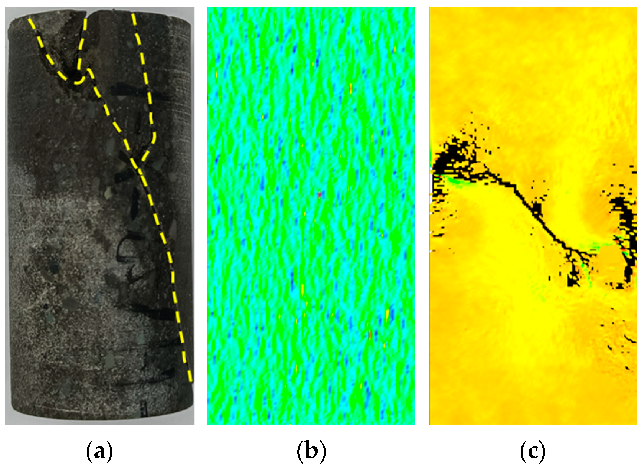
Figure 2b,c shows the stress profiles of the rock samples before and after the experiment, respectively. As illustrated in
Figure 2, it is evident that the simulated results and the experimental results are in excellent agreement.
Figure 3 shows the stress-strain relationship obtained from the numerical result and experimental result. Initially, the deformation is linearly elastic. As the strain increases, the rock sample gradually reaches its peak strength and begins to generate microcracks, meaning that the rock strength degrades. Because of the heterogeneity of the rock material, local stress concentration occurs. Microfractures are first generated at the area of stress concentration and then propagate continuously until they completely pass through the specimen.
4. Results and Analysis
When fracture extension in fractured-vuggy carbonate reservoirs is being numerically simulated, whether the hydraulic fractures can connect a natural karst cave depends on how hydraulic fractures interact with the cave. Their interaction is subject to many factors. To analyze how hydraulic fracture interacts with the cave, the following numerical simulations are run.
The shape of natural caves in reservoirs is generally irregular, in order to facilitate modeling, we use a circle cave model as the simulation object in the present study. Height displacement is set to 0 under the assumption of planar strain,
Figure 4 shows the geometry of the simulation model, the location of the wellbore and the cave, and Young’s modulus distribution. The size of the fracture was transformed using the similarity criterion. The computational model is a laboratory-scale, two-dimensional reservoir model. The entire model is made up of 90,000 four-node isoparametric quadrilateral units with a dimension of 300 mm × 300 mm. The scales of the latter simulation results are all consistent with
Figure 4. A wellbore is located close to the left side. The fracturing fluid is pumped into the model through a wellbore at a fixed pace. The diameter of the wellbore is 10 mm. To better control the direction of hydraulic fracture propagation, 5 mm microcracks are preset as perforations on both sides of the horizontal direction of the wellbore. The cave lies 80 mm directly east of the wellbore and has a diameter of 30 mm The specific basic input parameters of the model are shown in
Table 1.
4.1. Effect of Heterogeneity
Rock medium is a typical heterogeneous material. Compared with the assumption that the model is homogeneous, the seepage-stress coupling mechanism of heterogeneous materials is more complex and more in accordance with the engineering reality. Furthermore, the fracture expansion trajectory is significantly impacted by the heterogeneity of the matrix rock. The mechanical characteristics of the matrix rock are adjusted to obey the Weibull distribution (m). This section discusses how matrix heterogeneity affects the interaction between a cave and a fracture. The matrix heterogeneity is set to 4, 10, and 100 when the elastic modulus is 50 GPa. And other parameters are set as the same as those in
Table 1.
As shown in
Figure 5, when homogeneity index m is 4 indicating a high heterogeneity, the model contains a large number of defective units, which have low mechanical strength. The fracture morphology is rough with a narrow width. When the fracture extends to the vicinity of the cave, the fracture propagation trajectory is deflected due to stress concentration around the cave. It basically coincides with the findings of Cheng et al. (2019) [
17] and Wang et al. (2021) [
18] that hydraulic fracture is apt to bypass the cave because of the repulsion effect of the cave. In this study, due to the higher in-situ stress difference, the random distribution of defective units in the rock has a limited effect on fracture extension. As homogeneity of the rock increases, hydraulic fracture morphology gradually becomes flat and regular, and the width of the fracture gradually increases. When
m = 10 and
m = 100, the fracture propagation is hindered in the vicinity of the cave. The fracture morphology is discontinuous due to insufficient fracture pressure. But due to the influence of pore water pressure and stress, low-strength units around the cave have been damaged or even destroyed, forming a circular fracture near the cave. This is because, as the fracture extends, the pore water pressure near the fracture rises, decreasing the effective stress in the rock. If the deviatoric stress remains constant, the rock is more likely to reach ultimate strength, according to the Mohr-Coulomb criterion. According to the generalized Hooke law, the role of the pore water pressure is equivalent to a decrease in the magnitude of the confining pressure and thus reduces the residual strength of the rock.
Although the hydraulic fracture does not connect directly with the cave, there are a certain number of damage units distributed between the fracture and the cave, as shown in
Figure 6. These high-permeable damage units provide a seepage channel, which indirectly realizes the communication between the fracture and the cave. Under the same boundary conditions, the case of
m = 4 has the largest number of damaged units and the most dispersed distribution. As the homogeneity index increases, the distribution of damage units gradually changes from a point-like distribution to a block-like distribution, as does the area of the seepage channel between the fracture and the cave.
In general, rock heterogeneity, as a fundamental property of rock materials, affects the fracture propagation morphology and tends to cause hydraulic fractures to produce branching microfractures at the tip, resulting in a different hydraulic fracture morphology from that of homogeneous materials. As rock homogeneity increases, the hydraulic fracture propagation morphology becomes flat and smooth. But the heterogeneity has little impact on the interaction pattern between the fracture and the cave, and fractures bypass the cave at different degrees of homogeneity.
4.2. Effect of In-Situ Stress
The in-situ stress field is generally considered to play a crucial role in hydraulic fracture extension trajectory and final fracture morphology. Nevertheless, the stress field will vary as a result of the cave’s stress concentration, which might change the direction that a hydraulic fracture takes as it propagates. Meanwhile, the stress concentration effect of the cave can be significantly impacted by variations in in-situ stress, thus affecting the hydraulic fracture propagation trajectory. To explore the effect of the in-situ stress field on how the hydraulic fracture interacts with the cave, three cases are simulated in terms of the magnitude of the in-situ stress and the difference of the in-situ stress. And other parameters are set as the same as those in
Table 1.
For Case 1, we select a lower level of in-situ stress:
σh is 5 MPa and
σH is 10 MPa. We select a higher stress difference in Case 2:
σh is 5 MPa and
σH is 20 MPa. The stress difference in Case 3 is the same as in Case 2, but the stress level is higher:
σh is 50 MPa and
σH is 65 MPa.
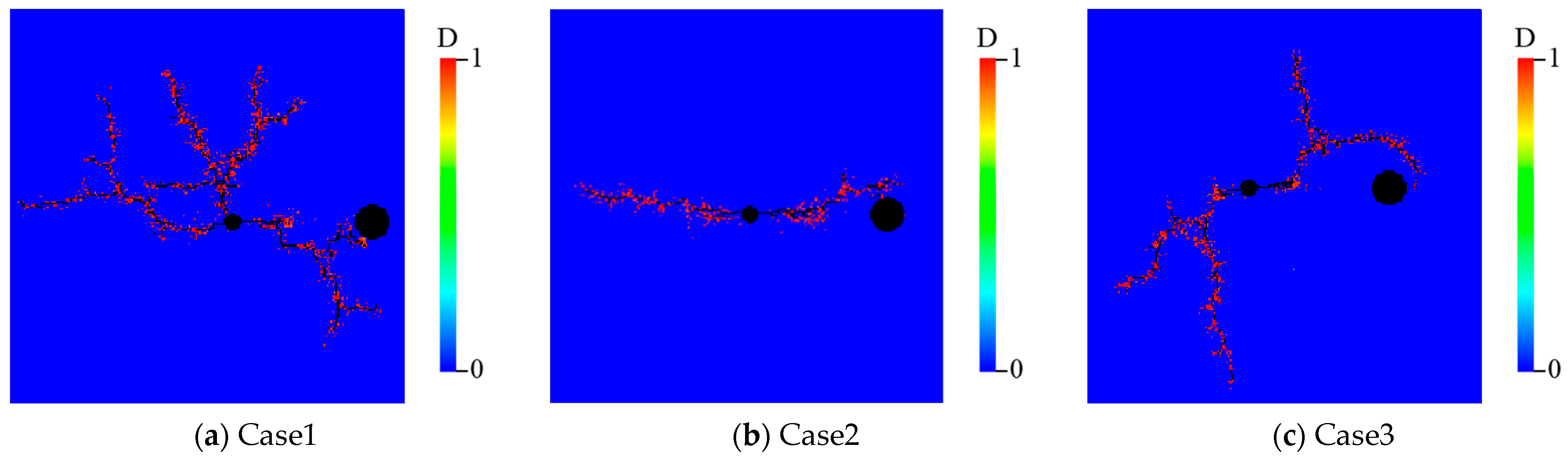
Figure 7 depicts the simulation’s findings, which reveal that due to the stress concentration in the cave’s vicinity, the fracture is repelled. Due to the rock material being heterogeneous, the stress state of each unit inside the model is different, resulting in non-uniform stress distribution in the model. Therefore, the local stress concentration caused by the impact of the surrounding pressure and pore water pressure leads to the destruction of some units, which are prone to producing multiple microfractures. To investigate how in-situ stress differences affect fracture-cave interaction patterns, by comparing Case 1 and Case 2, it can be found the lower in-situ stress difference in the reservoir is more likely to produce branch fractures. As demonstrated in
Figure 8, the fracture is also subject to stronger repulsion near the cave and does not connect to the cave even with the help of damaged units. As the in-situ stress difference rises, the in-situ stress field’s capacity to influence the hydraulic fracture expansion trajectory increases. resulting in the hydraulic fracture tending to maintain its original propagation path. In Case 2, small amounts of the fracture’s deflection allow it to connect with the cave through the high permeable damage units.
To investigate how in-situ stress magnitude impacts the pattern of fracture-cave interaction, Case 2 and Case 3 are compared. It is clear that even if the in-situ stress difference is the same, the cave repels the fracture in a very different way. The cave has a stronger repulsion effect when the in-situ stress magnitude is higher. Moreover, in Case 3, the hydraulic fracture also generates more branching fractures, which is caused by the increased size effect under the higher in-situ stress magnitude [
41].
When combined with the distribution of damage units, Case 2 is the only case that indirectly connects the fracture to the cave through the damage evolution of the rock material between the fracture and the cave. The findings indicate that connecting the fracture with the cave in the direction of maximal horizontal stress is advantageous due to the greater in-situ stress differential and lower in-situ stress magnitude.
4.3. Effect of Matrix Permeability
The matrix permeability is set to 0.01 mD, 0.1 mD, and 1 mD in order to study its impact. In addition, other parameters are specified to match those in
Table 1.
Figure 9 displays the simulation findings. When the reservoir permeability is 0.01 mD, the fracturing fluid loss is low and the fracture pressure is very high, leading to a relatively regular double-wing fracture. The fracture is deflected to some extent by the stress concentration near the cave, but there are a certain number of highly permeable damage units between the fracture and the cave, according to
Figure 10. As the permeability rises, the amount of fracturing fluid loss raises, and the pore water pressure spreads over a larger area, which tends to generate branching fractures. Therefore, when the reservoir permeability is 1 mD, due to the formation of complex branching fractures, the net pressure in a fracture is low relatively, resulting in a larger deflection under the influence of the cave. It is difficult for a hydraulic fracture to establish a connection with a karst cave. The matrix permeability affects the energy at the fracture tip, which in turn affects fracture length. In the case of high permeability, the energy at the fracture tip is insufficient to support the formation of long hydraulic fractures due to the large fracturing fluid leak-off. Moreover, the fracture morphology is complicated because of the generation of complex branching fractures, and it is challenging to regulate the direction in which the hydraulic fracture propagates. In general, the higher permeability can lead to insufficient net pressure in the fracture, which will be detrimental to the connection behavior between the fracture and the cave.
4.4. Effects of Fluid Pressure in the Cave
In reality, the majority of caves in carbonate reserves are stocked with gases and liquids like oil. Compared to empty holes, the mechanical properties and stress are different. To study the effect of fluid pressure in the cave on the interaction between fracture and cave, the fluid pressure in the cave is set to 5 MPa (Case 1), 10 MPa (Case 2), and 15 MPa (Case 3). And other parameters are set as the same as those in
Table 1.
Figure 11,
Figure 12 and
Figure 13 depict the progression of simulated hydraulic fractures and the distribution of water pressure for Cases 1, 2, and 3. When the fluid pressure within the cave reaches 5 MPa, the hydraulic fracture is strongly repulsed close to the cave. The propagation trajectory of hydraulic fracture is only a little influenced by the fluid pressure inside the cave. According to
Figure 12, the hydraulic fracture has three branching propagations along with different directions at the step of 190 when the fluid pressure in the cave is 10 MPa. However, at step 209, hydraulic fracture successfully communicates with the cave and passes through the cave at step 229, which does not exhibit the repulsion effect of the cave. Although the fracture morphology is discontinuous in the vicinity of the cave, there are a lot of damage units near the cave to serve as effective seepage channels, as shown in
Figure 14. The reason for this is that when a cave is filled with fluid, the fluid pressure on the cave wall transforms the original tangential compressive stress on the cave wall into tensile stress. As the fluid pressure in the cave increases, the wall of the cave gradually changes from a compressed state to a tensioned state, which weakens the effects of the compressive stress concentration around the cave. As shown in
Figure 13, when the fluid pressure in the cave is 15 MPa, under the combined action of pore water pressure and fluid pressure in the cave, the wall of the cave reaches ultimate strength and ruptures to form fractures at the step of 149. When hydraulic fracture and the cave-generated fracture are close to each other, they attract each other at step 189, because there are a considerable number of damage units between the fractures. As more fracturing fluid is injected, in the direction of the non-maximum principal stress, hydraulic fracture generates branching fracture, resulting in insufficient net pressure within the fracture, which in turn makes hydraulic fracture not directly connected to the cave. However, based on the distribution of damage units, hydraulic fracture connects with the cave through high permeable damage units, according to
Figure 14.
4.5. Effect of Injection Rate
The rate of fracturing fluid injected into the hydraulic fracture throughout the process can have a direct impact on the hydraulic fracture’s net pressure, which further changes the morphology of the hydraulic fracture. Therefore, it is crucial to consider the rate of fracturing fluid injection when the hydraulic fracturing construction is designed. To explore how fracturing fluid injection rate affects the interaction pattern between the cave and hydraulic fracture, we simulate three kinds of injection rate cases: 5 × 10⁻⁹ m3/s (Case 1), 5 × 10⁻⁸ m3/s (Case 2), and 5 × 10⁻⁷ m3/s (Case 3) respectively.
As the injection rate rises under the same reservoir conditions, the fracture morphology is quite different.
Figure 15,
Figure 16 and
Figure 17 depict the progression of simulated hydraulic fractures and the distribution of water pressure for Cases 1, 2, and 3, respectively. When the injection rate is 5 × 10
−9 m
3/s, the net pressure in the fracture is so low that the fracture is strongly repelled near the cave. When the injection rate increases to 5 × 10
−8 m
3/s, the hydraulic fracture morphology becomes more complex, which makes the influence of heterogeneity more prominent. At step 249, hydraulic fracture produces a branching fracture in the vicinity of the cave, one end bypassing the cave and the other being blocked by the stress concentration around the cave. However, as more fracturing fluid is injected, many block damage units are generated, and eventually destroyed in the area between the fracture and the cave, allowing the fracture to be connected to the cave at the step of 269, due to the combined impact of pore water pressure and increased fracture pressure. When the injecting rate continues increasing to 5 × 10
−7 m
3/s, the fluid pressure in the fracture rises rapidly, reaching 112 MPa at the step of 119. The high water pressure acts as a dilatant in the fracture and intensifies the fracturing process. The fracture pressure is high enough that it plays a leading role in fracture propagation, resulting in that hydraulic fracture can directly break through the repulsion of the cave to pass through it, at the step of 169. According to the water pressure distribution evolution process, it is found that the water pressure in the fracture lowers dramatically at the moment of the connection between the fracture and the cave. And not only does the fracture width increase, but also the propagation morphology of hydraulic fracture becomes smooth and straight, only generating a few branching microfractures. More, as shown in
Figure 18, it can be seen from the distribution of damaged units that the number of damaged units is the highest with a concentrated and block-like distribution and close to a block distribution when the injecting rate is 5 × 10
−7 m
3/s.
5. Conclusions
This study uses the finite element method and statistical damage mechanics theory to construct a coupled seepage-stress-damage model for a fractured-vuggy carbonate reservoir. Through this method, the effects of heterogeneity, in-situ stress, matrix permeability, fracturing fluid injection rate, and fluid pressure in the cave on how hydraulic fracture interacts with the cave are investigated. It is found that although the fracture propagation mechanism based on damage mechanics is different from the commonly used fracture mechanics, the simulation results in this paper show that the hydraulic fracture will bypass the cavity due to the strong stress concentration around the cave, which is consistent with previous research. The distinction is that the local stress and seepage fields are significantly influenced by the presence of damaged units. The following is a summary of the key findings:
(1) Hydraulic fracture bypasses the cave due to the strong stress concentration surrounding the cave. But the distribution of damage units shows that when the deflection degree of fracture is small, the fracture can indirectly connect with the cave through the high permeability damage units.
(2) Rock heterogeneity affects the fracture propagation morphology. The hydraulic fracture propagation morphology becomes flat and smooth as rock homogeneity rises. But the heterogeneity has little effect on how hydraulic fracture interacts with the cave, and the fracture bypasses the cave under different degrees of homogeneity.
(3) How hydraulic fracture interacts with the cave is significantly influenced by the in-situ stress magnitude as well as the in-situ stress differential. The ability of a cave to repel hydraulic fracture is proportional to the magnitude of the in-situ stress. And the higher in-situ stress difference can cause a fracture to stick to its original propagation path, limiting the deflection of the fracture.
(4) The higher permeability can lead to insufficient net pressure in the fracture, which is bad for connecting the fracture to the cave.
(5) As fluid pressure in the cave rises, the cave wall gradually changes from a compressed to a tensioned state, weakening the compressive stress concentration effect near the cave.
(6) The hydraulic fracture can propagate along its initial trajectory because of the high injection rate’s ability to lessen the impact of the cave.


